

MSI MS-7667 User Manual
Thank you for choosing the 7667 v2.2 Series (MS-7667)
Micro-ATX mainboard. The series mainboards are based
on Intel® P67 chipsets for optimal system eciency.
Designed to t the advanced Intel® LGA1155 processor,
the series deliver a high performance and professional
desktop platform solution.
Chapter 1
Getting Started
1-2
Getting Started
Mainboard Specications
Processor Support
Intel® Sandy Bridge processor in the LGA1155 package
Chipset
Intel® P67 chipset
Memory Support
4 DDR3 DIMMs support DDR3 2133(Over Clocking)/ 1600(Over Clocking)/ 1333/
1066 DRAM (32GB Max)
Supports Dual-Channel mode
LAN
Supports LAN 10/100/1000 by Realtek® RTL8111E
IEEE 1394
1 IEEE 1394 rear port by VIA® VT6315N
Audio
Chip integrated by Realtek® ALC892
Flexible 8-channel audio with jack sensing
Compliant with Azalia 1.0 Spec
SATA
4 SATA 3Gb/s ports (SATA3~6 by Intel® P67 PCH)
2 SATA 6Gb/s ports (SATA1~2 by Intel® P67 PCH)
2 eSATA ports (rear x 1, front x 1) by JMicron® JMB362
RAID
SATA1~6 support Intel® Matrix Storage Technology (AHCI/ RAID 0/ 1/ 5/ 10) by Intel
®
P67 PCH
2 eSATA ports support RAID 0/ 1 & JBOD mode by JMicron® JMB362
USB 3.0
2 USB 3.0 ports by RENESAS uPD720200AF1-DAP-A
■
■
■
■
■
■
■
■
■
■
■
■
■
■
■
1-3
MS-7667
Chapter 1
Connectors/ Ports
Back panel
1 Coaxial S/PDIF-Out
1 Optical S/PDIF-Out
1 IEEE 1394 port
6 USB 2.0 ports
1 eSATA port
1 LAN port
6 exible audio ports
On-Board
2 USB 2.0 connector
2 USB 3.0 ports
1 Front Panel Audio connector
1 OC switch /LED connector
Slots
2 PCIE 2.0 x16 slots
2 PCIE 2.0 x1 slots
Form Factor
Micro-ATX (24.4 cm X 24.4 cm)
Mounting
8 mounting holes
■
-
-
-
-
-
-
-
■
-
-
-
-
■
■
■
■
1-4
Getting Started
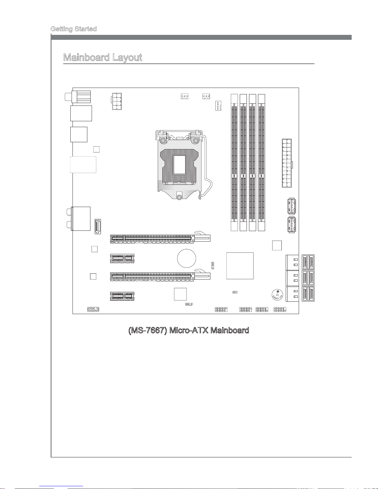
(MS-7667) Micro-ATX Mainboard
Mainboard Layout
PASS WOR D
USB 2
SYS FAN1 SYS FAN2
CPU _FAN
USB 1
JFP 3
FRO NT_ PANEL
CLE AR_ CMO S
SLOT1
DIMM1
DIMM
3
DIMM2
DIMM4
SLOT2
SLOT3
SLOT4
ESA
TA
FRO NT_ AUD IO
BATT
+
LOC K
Top: LAN Ja ck
Bot tom : U SB2. 0 por ts
T:
M:
B:
Lin e-O ut
Lin e-I n
Mic
T:CS- Out
M:R S-O ut
B:S S-O ut
Top: USB 2. 0 p ort s
Bot tom : e SATA port
Top:
Bot tom :
139 4 p ort
USB 2. 0 p ort s
Top:
Coa xia l S /PDI F
But tom :
Opt ica l S /PDI F
U
SB3 _2
U
SB3 _1
PWR 1
PWR 2
SA
TA
1_2
SA
TA
3_4
SA
TA
5_6

This chapter provides you with the information about
hardware setup procedures. While performing the installation, be careful in holding the components and following the installation procedures. For some components, if
you install in the wrong orientation, the components will
not work properly.
Use a grounded wrist strap before handling computer
components. Static electricity may damage the components.
Chapter 2
Hardware Setup
2-2
Hardware Setup
MS-7667
Chapter 2
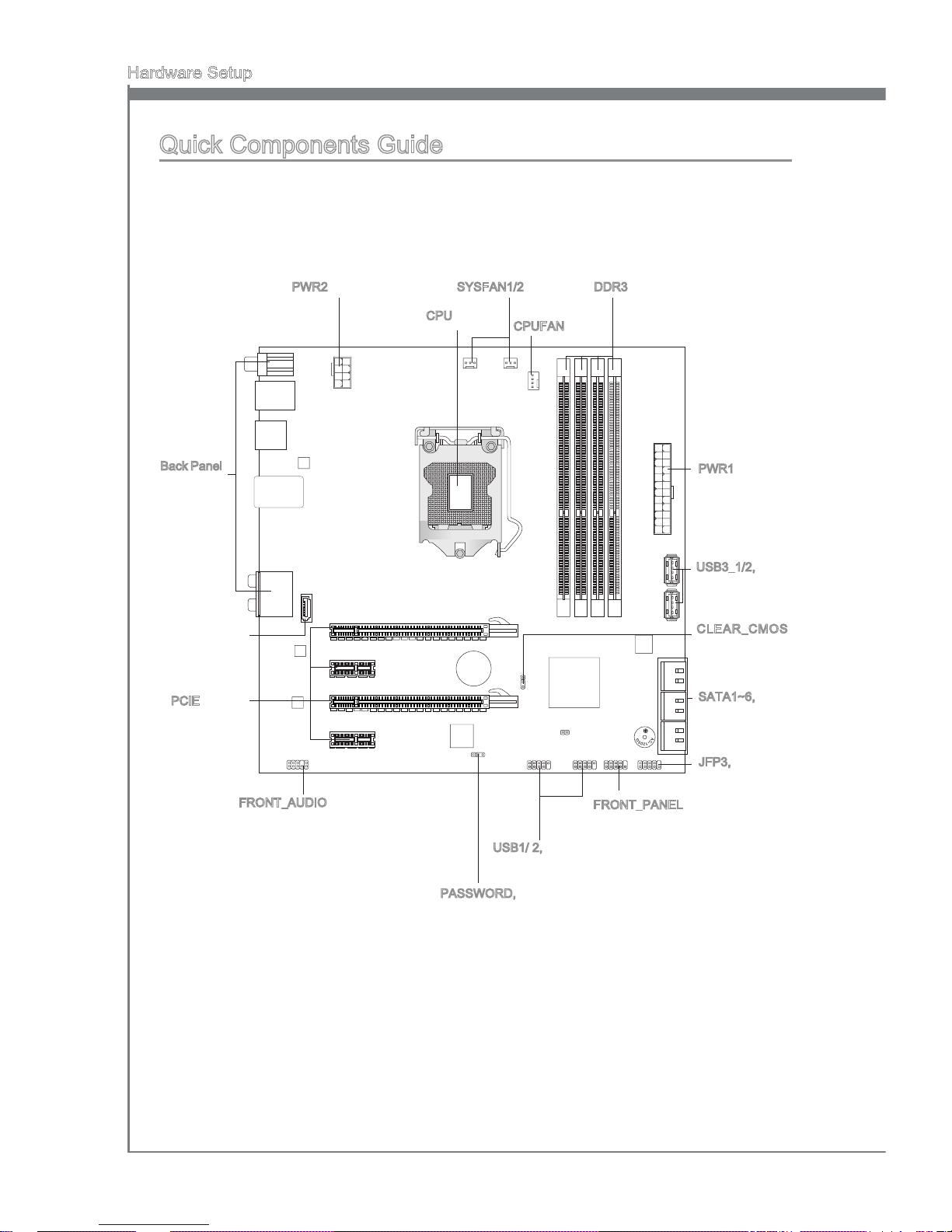
Quick Components Guide
Back Panel,
p.2-11
CPU, p.2-4
CPUFAN, p.2-14
DDR3, p.2-8PWR2, p.2-10
PWR1, p.2-10
CLEAR_CMOS,
p.2-17
SATA1~6, p.2-13
JFP3, p.2-16
FRONT_PANEL, p.2-14
USB3_1/2, p.2-15
FRONT_AUDIO, p.2-16
PCIE, p.2-18
SYSFAN1/2, p.2-14
PASSWORD, p.2-17
USB1/ 2, p.2-15
ESATA, p.2-13
MS-7667
Chapter 2
2-3
MS-7667
Chapter 2
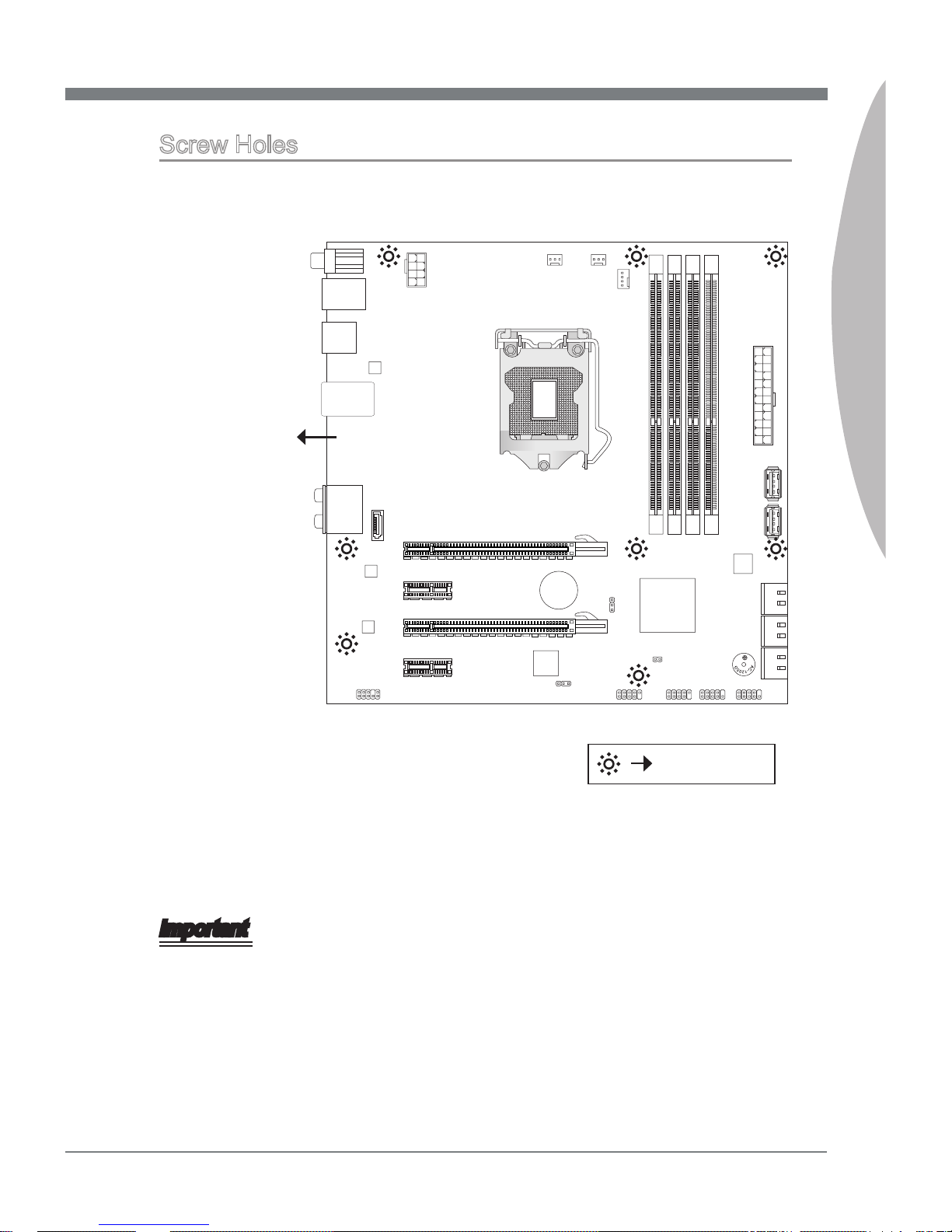
Screw Holes
When you install the mainboard, you have to place the mainboard into the chassis in the
correct direction. The locations of screws holes on the mainboard are shown as below.
Refer above picture to install standos in the appropriate locations on chassis and then
screw through the mainboard screw holes into the standos.
Important
To prevent damage to the mainboard, any contact between the mainboard circuit and
chassis or unnecessary standos mounted on the chassis is prohibited.
Please make sure there are no metal components placed on the mainboard or within
the chassis that may cause short circuit of the mainboard.
•
•
Screw holes
The side has to
toward the rear,
the position for
the I/O shield of
the chassis.
 Loading...