


Fuzzy GM965/GME965
MS-9803 (V1.X) Mainboard
G52-98031X3
i

Copyright Notice
The material in this document is the intellectual property of MICRO-STAR INTERNATIONAL. We take every care in the preparation of this document, but no guarantee is given as to the correctness of its contents. Our products are under continual improvement and we reserve the right to make changes without notice.
Trademarks
All trademarks are the properties of their respective owners.
Intel® and Pentium® are registered trademarks of Intel Corporation.
AMD, Athlon™, Athlon™ XP, Thoroughbred™, and Duron™ are registered trademarks of AMD Corporation.
NVIDIA, the NVIDIA logo, DualNet, and nForce are registered trademarks or trademarks of NVIDIA Corporation in the United States and/or other countries.
PS/2 and OS®/2 are registered trademarks of International Business Machines Corporation.
Windows® 95/98/2000/NT/XP are registered trademarks of Microsoft Corporation. Netware® is a registered trademark of Novell, Inc.
Award® is a registered trademark of Phoenix Technologies Ltd. AMI® is a registered trademark of American Megatrends Inc.
Revision History
Revision |
Revision History |
Date |
V1.2 |
Marking the CF slot as an option |
November 2007 |
Technical Support
If a problem arises with your system and no solution can be obtained from the user’s manual, please contact your place of purchase or local distributor. Alternatively, please try the following help resources for further guidance.
 Visit the MSI website at http://global.msi.com.tw/index.php? func=faqIndex for FAQ, technical guide, BIOS updates, driver updates, and other information.
 Contact our technical staff at http://support.msi.com.tw/.
ii

Safety Instructions
1.Always read the safety instructions carefully.
2.Keep this User’s Manual for future reference.
3.Keep this equipment away from humidity.
4.Lay this equipment on a reliable flat surface before setting it up.
5.The openings on the enclosure are for air convection hence protects the equipment from overheating. DO NOT COVER THE OPENINGS.
6.Make sure the voltage of the power source and adjust properly 110/220V before connecting the equipment to the power inlet.
7.Place the power cord such a way that people can not step on it. Do not place anything over the power cord.
8.Always Unplug the Power Cord before inserting any add-on card or module.
9.All cautions and warnings on the equipment should be noted.
10.Never pour any liquid into the opening that could damage or cause electrical shock.
11.If any of the following situations arises, get the equipment checked by service personnel:
The power cord or plug is damaged. Liquid has penetrated into the equipment.
The equipment has been exposed to moisture.
The equipment does not work well or you can not get it work according to User’s Manual.
The equipment has dropped and damaged. The equipment has obvious sign of breakage.
12.DONOT LEAVE THIS EQUIPMENT INANENVIRONMENT UNCONDITIONED, STORAGE TEMPERATURE ABOVE 600 C (1400F), IT MAY DAMAGE THE EQUIPMENT.
CAUTION: Danger of explosion if battery is incorrectly replaced. Replace only with the same or equivalent type recommended by the manufacturer.
iii
FCC-B Radio Frequency Interference Statement
This equipment has been tested and found to comply with the limits for a Class B digital device, pursuant to Part
15 of the FCC Rules. These limits are designed to provide reasonable protection against harmful interference in a residential installation. This equipment generates, uses and can radiate radio frequency energy and, if not installed and used in accordance with the instructions, may cause harmful interference to radio communications. However, there is no guarantee that interference will not occur in a particular installation. If this equipment does cause harmful interference to radio or television reception, which can be determined by turning the equipment off and on, the user is encouraged to try to correct the interference by one or more of the measures listed below.
Reorient or relocate the receiving antenna.
Increase the separation between the equipment and receiver.
Connect the equipment into an outlet on a circuit different from that to which the receiver is connected.
Consult the dealer or an experienced radio/television technician for help.
Notice 1
The changes or modifications not expressly approved by the party responsible for compliance could void the user’s authority to operate the equipment.
Notice 2
Shielded interface cables and A.C. power cord, if any, must be used in order to comply with the emission limits.
VOIR LANOTICE D’INSTALLATIONAVANTDE RACCORDER AU RESEAU.
Micro-Star International
MS-9803
This device complies with Part 15 of the FCC Rules. Operation is subject to the following two conditions:
(1)this device may not cause harmful interference, and
(2)this device must accept any interference received, including interference that may cause undesired operation.
iv

WEEE (Waste Electrical and Electronic Equipment) Statement
v

vi

vii
|
CONTENTS |
|
Copyright Notice .................................................................................................... |
ii |
|
Trademarks ............................................................................................................ |
ii |
|
Revision |
History .................................................................................................... |
ii |
Technical |
Support ................................................................................................. |
ii |
Safety Instructions ................................................................................................ |
iii |
|
FCC-B Radio Frequency Interference Statement ................................................... |
iv |
|
WEEE (Waste Electrical and Electronic Equipment) Statement ................................ |
v |
|
Chapter 1 Product Overview .......................................................................... |
1-1 |
|
Mainboard Specifications ............................................................................. |
1-2 |
|
Block Diagram ............................................................................................... |
1-4 |
|
Mainboard Layout ........................................................................................ |
1-5 |
|
Board Dimension .......................................................................................... |
1-6 |
|
Back Panel & I/O Shield Drawing .................................................................. |
1-7 |
|
Power Consumption .................................................................................... |
1-8 |
|
Safety Compliance & MTBF .......................................................................... |
1-9 |
|
Chapter 2 Hardware Setup ............................................................................. |
2-1 |
|
Quick Components Guide ............................................................................. |
2-2 |
|
CPU (Central Processing Unit) ...................................................................... |
2-3 |
|
Memory ....................................................................................................... |
2-6 |
|
Power Supply .............................................................................................. |
2-7 |
|
Back Panel ................................................................................................... |
2-8 |
|
Connector .................................................................................................. |
2-10 |
|
Jumper ...................................................................................................... |
2-18 |
|
Slot ............................................................................................................ |
|
2-19 |
Chapter 3 BIOS Setup ...................................................................................... |
3-1 |
|
Entering Setup ............................................................................................. |
3-2 |
|
The Menu Bar .............................................................................................. |
3-4 |
|
Main ............................................................................................................. |
|
3-5 |
Advanced .................................................................................................... |
3-6 |
|
Boot ........................................................................................................... |
|
3-17 |
Security ..................................................................................................... |
3-21 |
|
Chipset ...................................................................................................... |
3-22 |
|
Exit ............................................................................................................ |
|
3-26 |
Chapter 4 System Resources ....................................................................... |
4-1 |
|
Watch Dog Timer Setting .............................................................................. |
4-2 |
|
AMI POST Code ........................................................................................... |
4-3 |
|
Resource List .............................................................................................. |
4-7 |
|
viii

Product Overview
Chapter 1
Product Overview
Thank you for choosing the Fuzzy GM965/GME965 (MS9803 v1.X) Mini ITX mainboard from MSI.
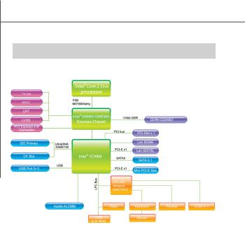
Based on the innovative Intel® GM965/GME965 & ICH8M controllers for optimal system efficiency, the Fuzzy GM965/GME965 accommodates the latest Intel® Core 2 Duo/Core Duo/Celeron M processors in Socket P and supports two 240-pin 533/667MHz DDR2 DIMM slots to provide the maximum of 4GB memory capacity.
In the entry-level and mid-range market segment, the Fuzzy GM965/GME965 can provide a high-performance solution for today’s front-end and general purpose workstation, as well as in the future.
1-1
 MS-9803 Mainboard
Mainboard Specifications
 Processor
-Intel Core 2 Duo/Core Duo/Celeron M CPU in Socket P
-Supports 3-pin CPU fan pin-header with Fan Speed Control
-Supports Intel Dual Core Technology to 533/667/800MHz and up
 Supported FSB
- 533/667/800MHz
 Chipset
-North Bridge: Intel GM965/GME965 chipset
-South Bridge: Intel ICH8M chipset
 Memo ry
-DDR2 533/667 SDRAM (4GB Max)
-2 DDR2 DIMM slots (240pin / 1.8V)
 LAN
LAN
- Supports 2 Gb Ethernet by Intel 82573L & 82566DC
 Audio
Audio
-HDA Codec by Realtek ALC888 7.1 channel
-Compliant with Azalia 1.0 specs
-6 watt amplifier
 IDE
IDE
-1 IDE port by ICH8M
-Supports Ultra DMA 66/100 mode
-Supports PIO, Bus Master operation mode
 SATA
SATA
-SATA II ports by ICH8M
-Supports two SATA II devices
-Supports storage and data transfers at up to 300MB/s
 Connectors
 Back Panel
-2 RJ-45 LAN jacks
-4 USB 2.0 ports
-1 D-Sub VGA connector
-1 serial port
1-2
Product Overview
-1 PS2 keyboard/mouse port
-6 audio jacks
 Onboard Connectors
-2 USB 2.0 connectors (4 ports)
-1 parallel port connector
-1 SPDIF connector
-1 LVDS connector
-1 TV-out connector
-1 digital I/O connector (16GPIO)
-1 serial port connector
-1 front panel connector
-1 amplifier connector (4-pin)
 Slots
Slots
-1 PCI Express x16 slot
-1 Mini PCI-E slot
-1 32-bit/33MHz PCI slot
-1 CF socket (optional)
Form Factor
- Mini ITX: 170mm x 170mm
Mounting
- 4 mounting holes
Environmental
 Storage Temperature
-Temperature: -20oC ~ 80oC
-Humidity: 0% RH ~ 95% RH
 Operation Temperature
-Temperature: 0oC ~ 55oC
-Humidity: 0% RH ~ 85% RH
1-3
 MS-9803 Mainboard
 Block Diagram
1-4
Product Overview
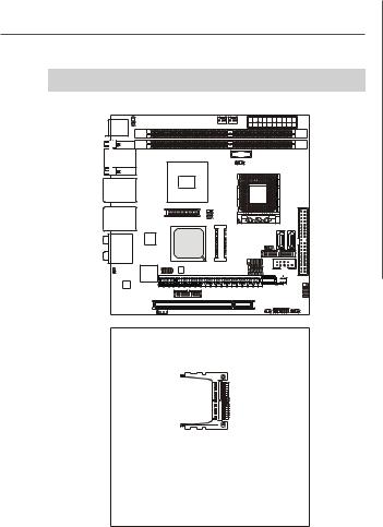
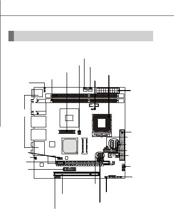
 Mainboard Layout
Top: |
J5 |
CPUFAN1 |
|
ATX1 |
|||
Mouse |
|
|
|
SYSFAN1 |
|
|
|
Bottom: |
|
|
|
|
|
|
|
Keyboard |
|
|
|
|
|
|
|
|
|
|
DIMM1 |
BATT |
|
|
|
Top: COM Port |
DIMM2 |
|
|
||||
+ JBAT1 |
|
|
|||||
Bottom: VGA Port |
Intel |
|
|
||||
|
|
|
GM965/GME965 |
|
|
|
|
Top: LAN Jack |
|
|
|
|
|
|
|
Bottom: USB Ports |
|
|
|
|
|||
|
|
|
JTV2 |
|
|
IDE1 |
|
|
|
|
|
|
|
||
Top: LAN Jack |
|
|
JLVDS1 |
|
SATA2 |
SATA1 |
|
Bottom: USB Ports |
CON1 |
||||||
|
|||||||
|
|
|
|
|
|||
T: Line-In |
|
Intel |
Intel |
|
|
|
|
M: Line-Out |
82566DC |
|
|
|
|||
ICH8M |
JCF_SEL1 |
|
|
||||
B: Mic |
|
|
|
|
|||
|
|
|
(Optional) |
|
|
||
T: RS-Out |
|
|
|
JLPT1 |
|
|
|
M: CS-Out |
|
|
|
|
|
||
B: SPDIF Out |
|
|
F_USB2 |
|
|
||
|
|
Intel |
JSPI2 |
F_USB1 |
|
|
|
JSPD1 |
|
PCI-E 1 |
COM2 |
||||
|
J7 |
||||||
|
|
82573L |
|
|
|
|
|
ALC888 |
|
|
|
|
|
JFP1 |
|
|
|
|
|
|
|
||
|
|
|
J4 |
|
|
|
|
|
|
|
|
|
JLPC1 |
J6 |
|
|
|
JAMP1 |
PCI1 |
JCASE1 |
|
||
|
|
|
|
||||
CF1
(Optional)
Fuzzy GM965/GME965 (MS-9803 v1.X) Mini ITX Mainboard
1-5

 MS-9803 Mainboard
Board Dimension
1-6

Product Overview
Back Panel & I/O Shield Drawing
1-7

 MS-9803 Mainboard
Power Consumption
|
Component |
|
Description |
|
|
|
|
|
|
|
|
CPU |
|
Intel Core 2 Duo T7100 processor |
|
|
|||||
|
Memory |
|
Kingston 2G DDR2-667 x2 |
|
|
|
|
|||
|
Add-On VGA |
|
Nvidia FX1400 PCI-Express VGA Card x1 |
|
|
|||||
|
Hard Disk |
|
Seagate 500G SATA2 7200rpm HDD x1 |
|
|
|||||
|
Operating system |
|
Microsoft® Windows XP® Professional SP2 |
|
|
|||||
|
|
|
|
|
|
|
|
|
|
|
|
MS-9803 |
3.3V |
5V |
|
12V |
12V Main |
5V Standby |
|
(-)12V |
|
|
|
|
|
|
|
Connector |
|
|
|
|
|
|
Current(A) |
Current(A) |
Current(A) |
Current(A) |
Current(A) |
Current(A) |
|||
Enter DOS(Stable) |
2.45 |
2.75 |
|
2.97 |
0 |
0.05 |
|
0.02 |
||
Enter BIOS(Stable) |
2.42 |
2.74 |
|
2.97 |
0 |
0.05 |
|
0.02 |
||
Idle |
1.64 |
2.37 |
|
1.92 |
0 |
0.05 |
|
0.01 |
||
CPU Stress 100% |
1.66 |
2.7 |
|
3.5 |
0 |
0.05 |
|
0.02 |
||
Windows stress(3dMARK2006) |
1.66 |
3.22 |
|
4.5 |
0 |
0.05 |
|
0.02 |
||
Windows Desktop Standby S1 |
1.08/1.07 |
1.78/1.76 |
|
1.58/1.56 |
0 |
0.08/0.080 |
|
0.02 |
||
with/without two LANs connected |
|
|
|
|
|
|
|
|
|
|
(stable) |
|
|
|
|
|
|
|
|
|
|
Windows Desktop Standby S3 |
0 |
0 |
|
0 |
0 |
0.45/0.44 |
|
0 |
||
with/without two LANs connected |
|
|
|
|
|
|
|
|
|
|
(stable) |
|
|
|
|
|
|
|
|
|
|
Windows Desktop Hibernate S4 |
0 |
0 |
|
0 |
0 |
0.25/0.24 |
|
0 |
||
with/without two LANs connected |
|
|
|
|
|
|
|
|
|
|
(stable) |
|
|
|
|
|
|
|
|
|
|
Windows Desktop Soft Off S5 |
0 |
0 |
|
0 |
0 |
0.25/0.24 |
|
0 |
||
with/without two LANs connected |
|
|
|
|
|
|
|
|
|
|
(stable) |
|
|
|
|
|
|
|
|
|
|
1-8

Product Overview
Safety Compliance & MTBF
Certification |
|
Standard number |
Title of standard |
|
|
EN 55022:1998+A1:2000+A2:2003 Class B |
Product family standard |
|
|
EN 6100-3-2:2000 Class D |
Limits for harmonic current |
|
RFI |
emission |
|
|
|
||
CE |
|
Limitation of voltage |
|
|
|
||
|
|
EN 6100-3-3:1995+A1:2001 |
fluctuation and flicker in low- |
|
|
|
voltage supply system |
|
Immunity |
EN 55024:1998+A1:2001+A2:2003 |
Product family standard |
BSMI |
CNS 13438 (1997 ) |
|
|
C-Tick |
AS/NZS CISPR 22:2004 |
|
|
FCC |
FCC CFR Title 47 Part 15 Subpart B: 2005 Class B |
|
|
CISPR 22: 2005 |
|
||
|
|
||
VCCI |
VCCI V-3:2004, Class B |
|
|
VCCI V-4:2004, Class B |
|
||
|
|
||
MTBF -Reliability Prediction
Calculation Model |
Operation |
Operating |
Duty Cycle |
MTBF (hr.) |
|
temperature ( ) |
Environment |
||||
|
|
|
|||
|
|
|
|
|
|
Telcordia Issue 1 |
35 |
GF, GU - Ground Fixed, |
10,867.351095 |
92,019 |
|
Uncontrolled |
|||||
|
|
|
|
||
|
|
|
|
|
|
MIL-HDBK-217 FN2 |
55 |
GF, GU - Ground Fixed, |
117.312341 |
8,524 |
|
Uncontrolled |
|||||
|
|
|
|
||
|
|
|
|
|
1-9

 MS-9803 Mainboard
1-10
Hardware Setup
Chapter 2
Hardware Setup
This chapter provides you with the information about hardware setup procedures. While doing the installation, be careful in holding the components and follow the installation procedures. For some components, if you install in the wrong orientation, the components will not work properly.
Use a grounded wrist strap before handling computer components. Static electricity may damage the components.
2-1
 MS-9803 Mainboard
Quick Components Guide
CPUFAN1, p.2-13 |
|
|
JTV2, p.2-14 |
SYSFAN1, |
|
|
p.2-13 |
|
JLVDS1, p.2-15 |
|
CPU, p.2-3 |
DIMM Slots, p.2-6 |
JBAT1, |
|
p.2-18 |
|
|
|
|
|
J5, p.2-18 |
|
|
|
|
ATX1, p.2-7 |
Back Panel |
|
|
I/O, p.2-8 |
|
|
|
|
IDE1, p.2-10 |
|
|
JCF_SEL1, p.2-20 |
|
|
SATA1/2, p.2-11 |
JSPI2, p.2-12 |
|
JLPT1, p.2-17 |
|
|
|
JSPD1, p.2-12 |
|
COM2, p.2-17 |
|
|
|
PCI-E Slot, |
|
|
p.2-19 |
|
JFP1, p.2-13 |
J4, p.2-11 |
|
|
|
|
|
|
|
J6, p.2-18 |
F_USB1/2, p.2-16 |
|
|
PCI Slot, p.2-19 |
JCASE1, p.2-10 |
|
|
|
|
J7, p.2-18
JAMP1, p.2-12
2-2
Hardware Setup
CPU (Central Processing Unit)
The mainboard supports Intel® Core 2 Duo/Core Duo/Celeron M processors in Socket P. When you are installing the CPU, make sure the CPU has a heat sink and a cooling fan attached on the top to prevent overheating. If you do not have the heat sink and cooling fan, contact your dealer to purchase and install them before turning on the computer.
Important
1.Overheating will seriously damage the CPU and system. Always make sure the cooling fan can work properly to protect the CPU from overheating.
2.Make sure that you apply an even layer of heat sink paste (or thermal tape) between the CPU and the heatsink to enhance heat dissipation.
3.While replacing the CPU, always turn off the power supply or unplug the power supply’s power cord from the grounded outlet first to ensure the safety of CPU.
2-3
 MS-9803 Mainboard
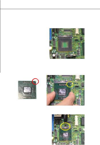
CPU & Cooler Installation for Socket P
1.Locate th e CPU socket on t he mainboard.
2.Place the CPU on top of the socket. Make sure to align the gold arrow on the CPU with the arrow key on the socket.
3.Push the CPU down until its pins securely fit into the socket.
4.On the front end of the CPU socket is a locking mechanism designed into the form of a screw head. Make sure that you actuate or deactuate this mechanism with a screwdriver before and after installing the CPU.
2-4

Hardware Setup
5.Flip over the mainboard and locate the position of the CPU socket.
6.Install the backplate to the back of the CPU socket with holes aligned.
CPU cooler backplate
7.The heatsink paste helps to enhance heat dissipation of the CPU. Before installing the cooler set (fan & heatsink bundled), make sure that you detach the shield of the heatsink paste under the cooler set.
8.Locate the four screw holes around the CPU socket where the CPU cooler backplate was installed. Align the cooler set with the screw holes and mount it on top of the CPU.
9.Screw to secure the cooler set to the mainboard.
10.Connect the fan power cable to the CPUFAN1 connector on the mainboard.
2-5
 Loading...