

Page 1
Quick Start
Thank you for purchasing the MSI® B450 GAMING PRO CARBON MAX WIFI
motherboard. This Quick Start section provides demonstration diagrams about how
to install your computer. Some of the installations also provide video demonstrations.
Please link to the URL to watch it with the web browser on your phone or tablet. You
may have even link to the URL by scanning the QR code.
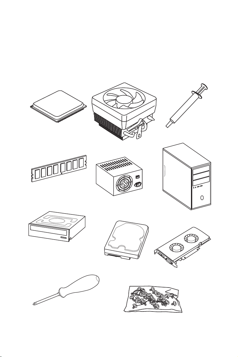
Preparing Tools and Components
AMD® AM4 CPU
DDR4 Memory
SATA DVD Drive
Thermal Paste
CPU Fan
Power Supply Unit
Chassis
SATA Hard Disk Drive
Graphics Card
Phillips Screwdriver
A Package of Screws
Quick Start
1
Page 2
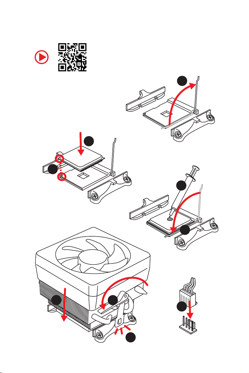
Installing a Processor
https://youtu.be/Xv89nhFk1vc
3
2
1
5
4
Quick Start
2
6
8
9
7
Page 3
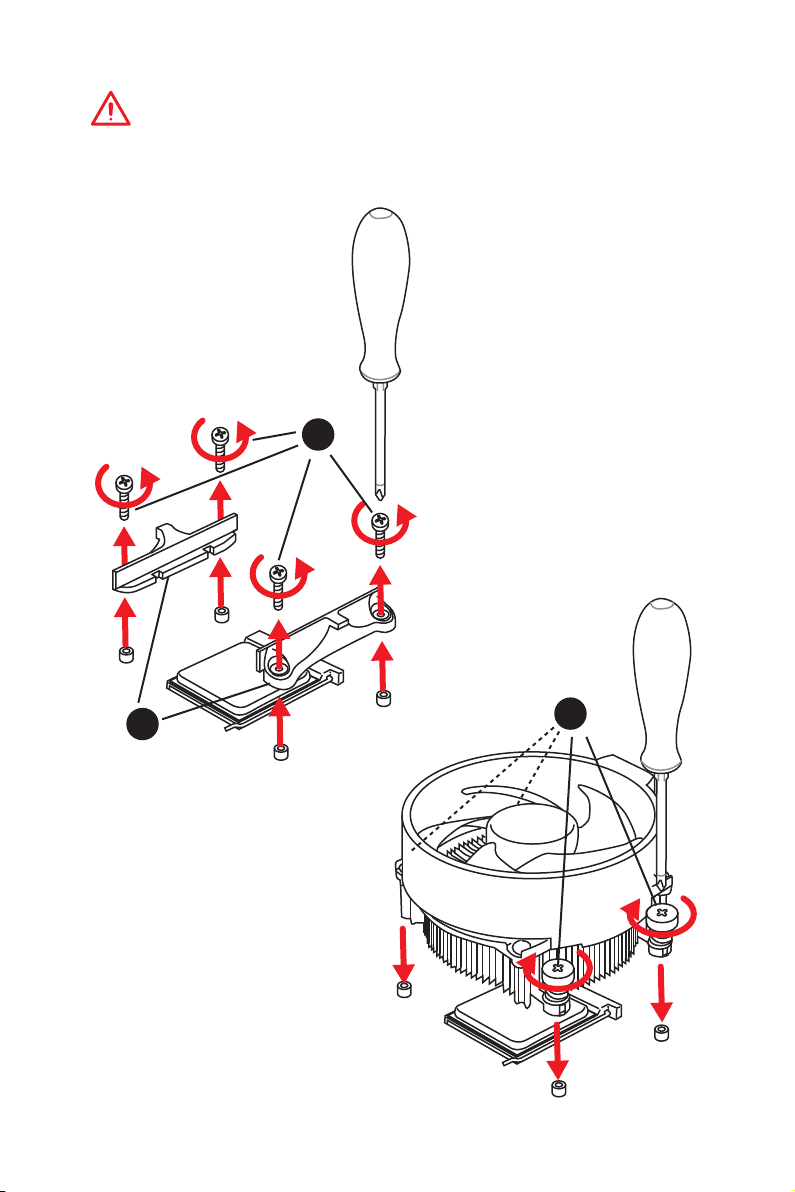
Important
If you are installing the screw-type CPU heatsink, please follow the figure below to
remove the retention module first and then install the heatsink.
1
2
3
Quick Start
3
Page 4
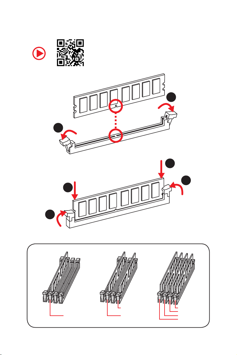
Installing DDR4 memory
http://youtu.be/T03aDrJPyQs
1
2
1
2
3
Quick Start
4
3
DIMMB2 DIMMB2
DIMMA2 DIMMA2 DIMMA2
DIMMB1
DIMMA1
Page 5
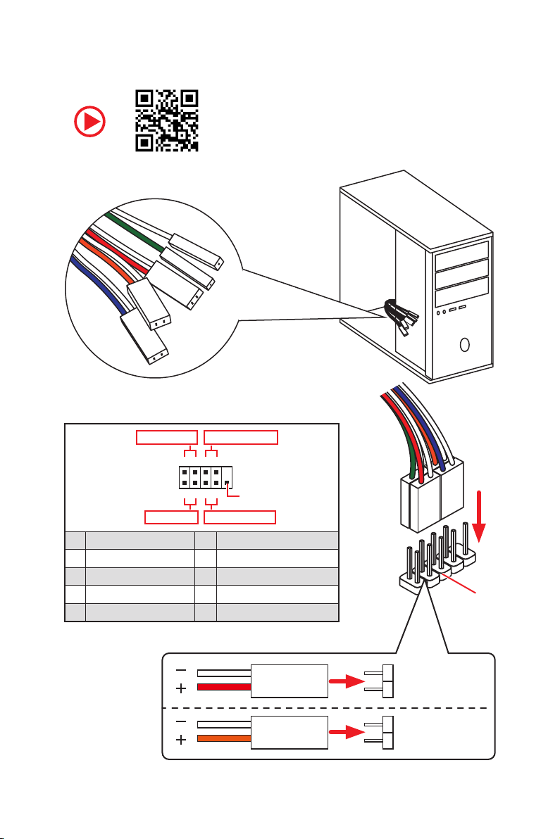
Connecting the Front Panel Header
RESET SW
POWER SW
POWER LED+
POWER LED-
HDD LED
http://youtu.be/DPELIdVNZUI
Power LED
JFP1
Power Switch
+++-
--
2 10
1
-
+
9
Reserved
HDD LED Reset Switch
1 HDD LED + 2 Power LED +
3 HDD LED - 4 Power LED -
5 Reset Switch 6 Power Switch
7 Reset Switch 8 Power Switch
9 Reserved 10 No Pin
HDD LED
POWER LED
HDD LED
HDD LED HDD LED +
POWER LED POWER LED +
Quick Start
RESET SW
JFP1
5
Page 6
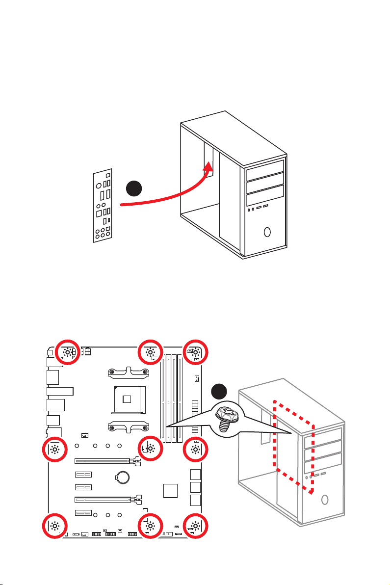
Installing the Motherboard
1
Quick Start
6
2
BAT1
Page 7
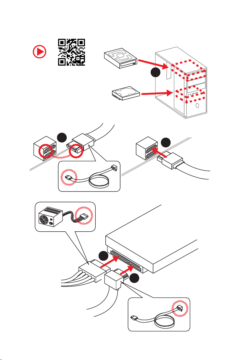
Installing SATA Drives
http://youtu.be/RZsMpqxythc
2
1
3
5
4
Quick Start
7
Page 8
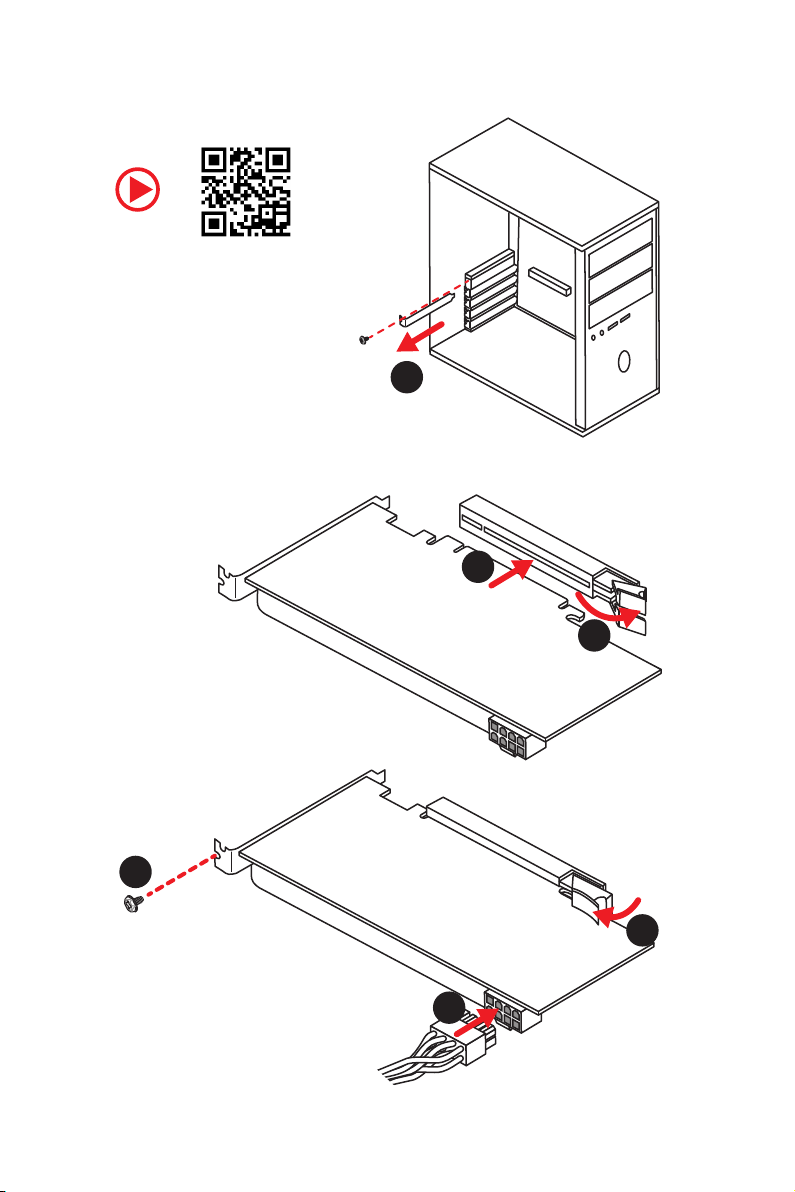
Installing a Graphics Card
http://youtu.be/mG0GZpr9w_A
1
3
2
Quick Start
8
5
4
6
Page 9
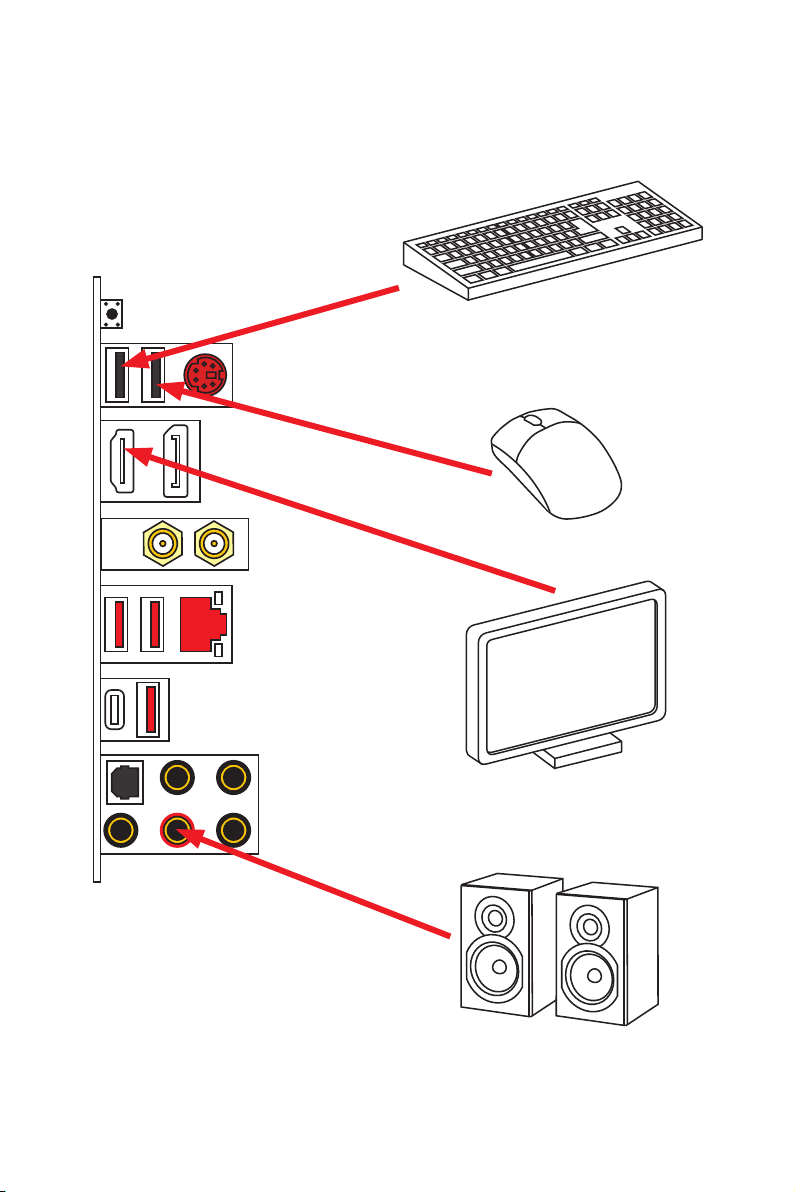
Connecting Peripheral Devices
Processor with integrated graphics
Quick Start
9
Page 10
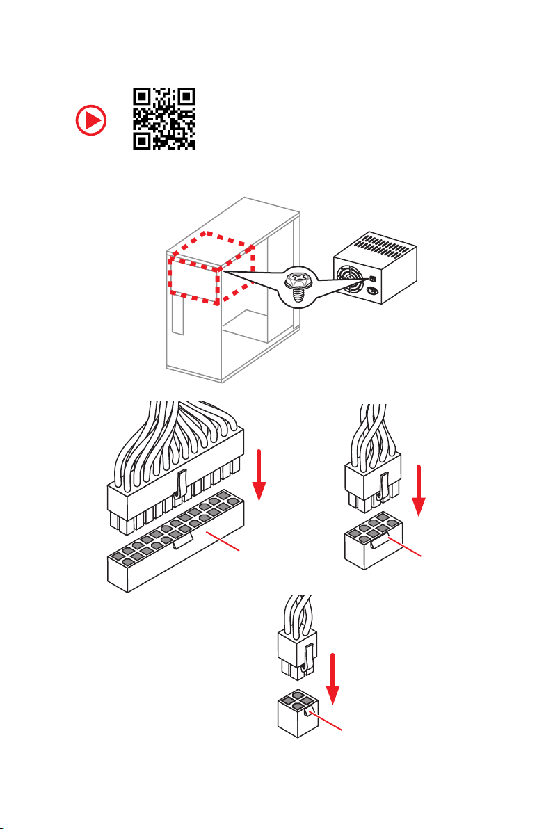
Connecting the Power Connectors
http://youtu.be/gkDYyR_83I4
10
Quick Start
ATX_PWR1
CPU_PWR1
CPU_PWR2
Page 11
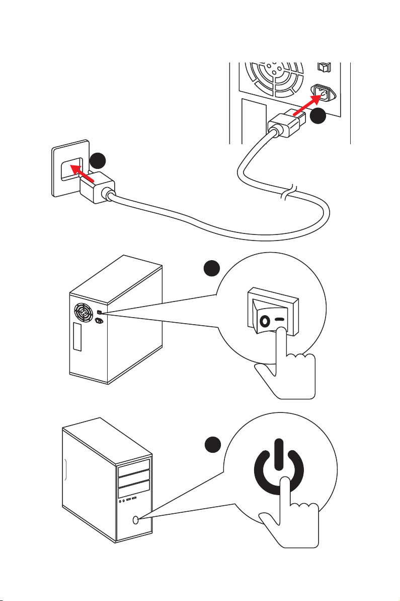
Power On
1
2
3
4
Quick Start
11
Page 12

Contents
Quick Start ............................................................................................................. 1
Preparing Tools and Components .......................................................................... 1
Installing a Processor ............................................................................................. 2
Installing DDR4 memory ........................................................................................ 4
Connecting the Front Panel Header ....................................................................... 5
Installing the Motherboard ..................................................................................... 6
Installing SATA Drives............................................................................................. 7
Installing a Graphics Card ...................................................................................... 8
Connecting Peripheral Devices .............................................................................. 9
Connecting the Power Connectors ....................................................................... 10
Power On............................................................................................................... 11
Safety Information ............................................................................................... 15
Specifications ....................................................................................................... 16
JCORSAIR1 Connector Specification ................................................................... 21
Package contents ................................................................................................ 22
Block Diagram .................................................................................................... 23
Rear I/O Panel ..................................................................................................... 24
LAN Port LED Status Table................................................................................... 24
Audio Ports Configuration .................................................................................... 24
Realtek Audio Console ......................................................................................... 25
Overview of Components .................................................................................... 28
Processor Socket .................................................................................................. 30
DIMM Slots ............................................................................................................ 31
PCI_E1~5: PCIe Expansion Slots .......................................................................... 32
M2_1~2: M.2 Slots (Key M) ................................................................................... 33
SATA1~6: SATA 6Gb/s Connectors ....................................................................... 34
JFP1, JFP2: Front Panel Connectors ................................................................... 34
CPU_PWR1~2, ATX_PWR1: Power Connectors ................................................... 35
JUSB1~2: USB 2.0 Connectors ............................................................................. 36
JUSB3: USB 3.2 Gen1 Connector ......................................................................... 36
CPU_FAN1, PUMP_FAN1, SYS_FAN1~4: Fan Connectors ................................... 37
JAUD1: Front Audio Connector ............................................................................37
JCI1: Chassis Intrusion Connector ....................................................................... 38
JCOM1: Serial Port Connector ............................................................................. 38
JTPM1: TPM Module Connector ........................................................................... 39
12
Contents
Page 13

JBAT1: Clear CMOS (Reset BIOS) Jumper ........................................................... 39
JRGB1~2, JRAINBOW1: RGB LED connectors ..................................................... 40
JCORSAIR1: CORSAIR Connector ........................................................................ 41
EZ Debug LED ....................................................................................................... 42
BIOS Setup ........................................................................................................... 43
Entering BIOS Setup ............................................................................................. 43
Resetting BIOS ...................................................................................................... 44
Updating BIOS ....................................................................................................... 44
EZ Mode ................................................................................................................ 46
Advanced Mode .................................................................................................... 48
SETTINGS .............................................................................................................. 49
Advanced ............................................................................................................... 49
Boot ....................................................................................................................... 54
Security ................................................................................................................. 54
Save & Exit ............................................................................................................ 56
OC .......................................................................................................................... 57
M-FLASH .............................................................................................................. 61
OC PROFILE .......................................................................................................... 62
HARDWARE MONITOR .......................................................................................... 63
Software Description ........................................................................................... 64
Installing Windows® 10 ......................................................................................... 64
Installing Drivers .................................................................................................. 64
Installing Utilities ................................................................................................. 64
APP MANAGER ..................................................................................................... 65
LIVE UPDATE 6 ...................................................................................................... 66
COMMAND CENTER ............................................................................................. 68
GAMING APP ......................................................................................................... 72
X-BOOST ............................................................................................................... 77
MYSTIC LIGHT ....................................................................................................... 79
MYSTIC LIGHT PARTY ........................................................................................... 83
SMART TOOL ......................................................................................................... 87
RAMDISK............................................................................................................... 89
GAMING LAN MANAGER ...................................................................................... 90
Nahimic 3 .............................................................................................................. 92
RAID Configuration .............................................................................................. 95
Using AMD RAID Controller BIOS Configuration Utility ....................................... 95
Initialize Disks ...................................................................................................... 97
Contents
13
Page 14

Create Arrays ........................................................................................................ 98
Delete Arrays ........................................................................................................ 99
Swap Arrays ........................................................................................................ 100
Manage Spares ................................................................................................... 101
Change the Controller Options ........................................................................... 102
Booting the system from an array ...................................................................... 102
Pausing the boot sequence for warning messages ........................................... 102
Change the Staggered Spinup Count ................................................................. 103
Using UEFI to create a 2.2TB RAID .................................................................... 104
Installing RAID Driver ......................................................................................... 105
Troubleshooting ................................................................................................ 106
Regulatory Notices ............................................................................................ 107
14
Contents
Page 15

Safety Information
y The components included in this package are prone to damage from electrostatic
discharge (ESD). Please adhere to the following instructions to ensure successful
computer assembly.
y Ensure that all components are securely connected. Loose connections may cause
the computer to not recognize a component or fail to start.
y Hold the motherboard by the edges to avoid touching sensitive components.
y It is recommended to wear an electrostatic discharge (ESD) wrist strap when
handling the motherboard to prevent electrostatic damage. If an ESD wrist strap is
not available, discharge yourself of static electricity by touching another metal object
before handling the motherboard.
y Store the motherboard in an electrostatic shielding container or on an anti-static pad
whenever the motherboard is not installed.
y Before turning on the computer, ensure that there are no loose screws or metal
components on the motherboard or anywhere within the computer case.
y Do not boot the computer before installation is completed. This could cause
permanent damage to the components as well as injury to the user.
y If you need help during any installation step, please consult a certified computer
technician.
y Always turn off the power supply and unplug the power cord from the power outlet
before installing or removing any computer component.
y Keep this user guide for future reference.
y Keep this motherboard away from humidity.
y Make sure that your electrical outlet provides the same voltage as is indicated on the
PSU, before connecting the PSU to the electrical outlet.
y Place the power cord such a way that people can not step on it. Do not place anything
over the power cord.
y All cautions and warnings on the motherboard should be noted.
y If any of the following situations arises, get the motherboard checked by service
personnel:
Liquid has penetrated into the computer.
The motherboard has been exposed to moisture.
The motherboard does not work well or you can not get it work according to user
guide.
The motherboard has been dropped and damaged.
The motherboard has obvious sign of breakage.
y Do not leave this motherboard in an environment above 60°C (140°F), it may damage
the motherboard.
Safety Information
15
Page 16

Specifications
Supports 1st, 2nd and 3rd Gen AMD Ryzen™/ Ryzen™ with
CPU
Chipset AMD
Memory
Expansion Slots
Radeon™ Vega Graphics and 2nd Gen AMD Ryzen™ with
Radeon™ Graphics/ Athlon™ with Radeon™ Vega Graphics
Desktop Processors for Socket AM4
* Please refer www.msi.com for more information on compatible memory.
* PCI_E2, PCI_E3, PCI_E4 and PCI_E5 slots will be unavailable when installing
M.2 PCIe SSD in M2_2 slot.
** PCI_E4 will run x1 speed when installing devices in any PCIe 2.0x1 slot.
®
B450 Chipset
y4x DDR4 memory slots, support up to 64GB*
Supports 1866/ 2133/ 2400/ 2667Mhz (by JEDEC)
Supports 2667/ 2800/ 2933/ 3000/ 3066/ 3200/ 3466 MHz
(by A-XMP OC MODE)
yDual channel memory architecture
ySupports non-ECC UDIMM memory
ySupports ECC UDIMM memory (non-ECC mode)
y 1x PCIe 3.0 x16 slot (PCI_E1)
Supports x16 speed with 1st, 2nd and 3rd Gen AMD
Ryzen™ processors
Supports x8 speed with Ryzen™ with Radeon™ Vega
Graphics and 2nd Gen AMD
®
Ryzen™ with Radeon™
Graphics processors
Supports x4 speed with Athlon™ with Radeon™ Vega
Graphics Processors
y 1x PCIe 2.0 x16 slot (PCI_E4, supports x4 mode)*/ **
y 3x PCIe 2.0 x1 slots*
®
y 1x DisplayPort, supports a maximum resolution of
4096x2304 @60Hz, 2560x1600 @60Hz, 3840x2160 @60Hz,
1920x1200 @60Hz*
Onboard Graphics
y 1x HDMI™ 1.4 port, supports a maximum resolution of
4096x2160 @30Hz, 2560x1600 @60Hz*
* Only support when using AMD® Ryzen™ with Radeon™ Vega Graphics/ Athlon™
with Radeon™ Vega Graphics Processors
* Maximum shared memory of 2048 MB
Multi-GPU y Supports 2-Way AMD® CrossFire™ Technology
Continued on next page
Specifications
16
Page 17

Audio
Storage
RAID
Continued from previous page
®
Realtek
ALC1220 Codec
y 7.1-Channel High Definition Audio
y Supports Optical S/PDIF output
®
B450 Chipset
AMD
y 4x SATA 6Gb/s ports
y 1x M.2 slot (M2_2, Key M)*
Supports PCIe 2.0 x4 2242/ 2260 /2280 storage devices
®
AMD
CPU
y 1x M.2 slot (M2_1, Key M)**
Supports PCIe 3.0 x4 (1st, 2nd and 3rd Gen AMD
Ryzen™/ Ryzen™ with Radeon™ Vega Graphics and 2nd
Gen AMD
®
Ryzen™ with Radeon™ Graphics) or PCIe 3.0
®
x2 (Athlon™ with Radeon™ Vega Graphics) and SATA
6Gb/s
Supports 2242/ 2260 /2280/ 22110 storage devices
y 2x SATA 6Gb/s ports**
* PCI_E2, PCI_E3, PCI_E4 and PCI_E5 slots will be unavailable when installing
M.2 PCIe SSD in M2_2 slot.
** SATA5 and SATA6 ports will be unavailable when installing a M.2 device in
M2_1 slot.
y Supports RAID 0, RAID 1 and RAID 10 for SATA storage
devices
y Supports RAID 0 and RAID 1 for M.2 NVMe RAID
®
AMD
1x USB 3.2 Gen2 (SuperSpeed USB 10Gbps) Type-C port
on the back panel
1x USB 3.2 Gen2 (SuperSpeed USB 10Gbps) Type-A port
on the back panel
2x USB 3.2 Gen1 (SuperSpeed USB) ports available
USB
through the internal USB 3.2 Gen1 connector
6x USB 2.0 (High-speed USB) ports (2 Type-A ports on
the back panel, 4 ports available through the internal
USB 2.0 connectors)
®
AMD
2x USB 3.2 Gen1 (SuperSpeed USB) Type-A ports on the
back panel
LAN 1x Intel
B450 Chipset
CPU
®
I211AT Gigabit LAN controller
Continued on next page
Specifications
17
Page 18

WiFi & Bluetooth
Back Panel
Connectors
Continued from previous page
®
Dual Band Wireless-AC 9260
Intel
Supports Wi-Fi 802.11 a/b/g/n/ac, dual band (2.4GHz,
5GHz) up to 1.73 Gbps speed.
Supports Dual Mode Bluetooth 2.1, 2.1+EDR, 3.0, 4.0,
BLE,4.2, 5.0
1 x M2_3 slot with E key (Wi-Fi mode)
y 1x Flash BIOS Button
y 1x PS/2 keyboard/ mouse combo port
y 2x USB 2.0 Type-A ports
y 1x DisplayPort
y 1x HDMI
™
port
y 2x WiFi Antenna connectors
y 1x LAN (RJ45) port
y 2x USB 3.2 Gen1 Type-A ports
y 1x USB 3.2 Gen2 Type-A port
y 1x USB 3.2 Gen2 Type-C port
y 5x audio jacks
y 1x Optical S/PDIF OUT connector
Continued on next page
18
Specifications
Page 19

Internal Connectors
Continued from previous page
y 1x 24-pin ATX main power connector
y 1x 8-pin ATX 12V power connector
y 1x 4-pin ATX 12V power connector
y 6x SATA 6Gb/s connectors
y 2x USB 2.0 connectors (support additional 4 USB 2.0 ports)
y 1x USB 3.2 Gen1 connectors (support additional 2 USB 3.2
Gen1 ports)
y 1x 4-pin CPU fan connector
y 1x 4-pin water-pump-fan connector
y 4x 4-pin system fan connectors
y 1x TPM module connector
y 1x Front panel audio connector
y 2x System panel connectors
y 1x Chassis Intrusion connector
y 1x Serial Port connector
y 1x Clear CMOS jumper
y 1x 2pin LED Power connector
y 2x 5050 RGB LED strip 12V connectors (JRGB1~2)
y 1x WS2812B Individually Addressable RGB LED strip 5V
connector (JRAINBOW1)
y 1x CORSAIR connector (JCORSAIR1)
I/O Controller NUVOTON NCT6797 Controller Chip
y CPU/System temperature detection
Hardware Monitor
Form Factor
BIOS Features
y CPU/System fan speed detection
y CPU/System fan speed control
y ATX Form Factor
y 12 in. x 9.6 in. (30.5 cm x 24.4 cm)
y 1x 256 Mb flash
y UEFI AMI BIOS
y ACPI 6.1, SM BIOS 2.8
y Multi-language
Continued on next page
Specifications
19
Page 20

Software
Special Features
Continued from previous page
y Drivers
y APP MANAGER
y SUPER CHARGER
y COMMAND CENTER
y LIVE UPDATE 6
y SMART TOOL
y RAMDISK
y X-BOOST
y GAMING APP
y MYSTIC LIGHT
y GAMING LAN MANAGER
y Nahimic Audio
y Open Broadcaster Software (OBS)
y CPU-Z MSI GAMING
™
y Norton
Internet Security Solution
y Google Chrome
™
, Google Toolbar, Google Drive
y Audio
Audio Boost
Nahimic 3
Voice Boost
y Storage
Twin Turbo M.2
y Cooling
Extended heastink
Pump Fan
GAMING Fan Control
y LED
Mystic Light
Mystic Light Extension
Mystic light SYNC
EZ DEBUG LED
20
Continued on next page
Specifications
Page 21

Special Features
Continued from previous page
y Protection
M.2 Shield
PCIe Steel Armor
PCIe Steel Slot
y Performance
Multi GPU-CrossFire Technology
DDR4 Boost
CORE Boost
GAME Boost
USB with type A+C
AMD Turbo USB 3.2 Gen 2
y Network
GAMING LAN with Gaming LAN Manager
Intel WiFi
y VR
VR Ready
y Gamer Experience
GAMING HOTKEY
GAMING MOUSE Control
y BIOS
Click BIOS 5
StoreMI
Flash BIOS Button
AMD FreeSync™ Ready
AMD Precision Boost OverDrive™
y Certification
GAMING Certified
JCORSAIR1 Connector Specification
Supporting CORSAIR RGB Products Maximum connection
Lighting PRO RGB LED Strip 7
HD RGB Fan 6
SP RGB Fan 6
LL RGB Fan 5
Specifications
21
Page 22

Package contents
Please check the contents of your motherboard package. It should contain:
y Motherboard
y Driver DVD
y User Manual
y Quick Installation Guide
y Case Stand-off Notification
y I/O Shielding
y Antenna x2
y SATA 6G Cable x2
y RGB LED Extension cable 80cm x1
y SATA Cable Labels
y Case Badge
y Product Registration Card
y M.2 Screw x1
Important
If any of the above items are damaged or missing, please contact your retailer.
Package contents
22
Page 23
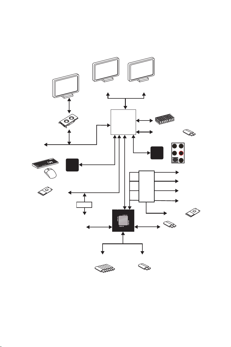
Block Diagram
HDMI DisplayPort
2 Channel DDR4 Memory
CPU
2x USB 3.2 Gen1
PCI Express Bus
NV6797
Super I/O
PS/2 Mouse / Keyboard
1 x M.2
2x SATA 6Gb/s
4x SATA 6Gb/s
SwitchSwitch
6 x USB 2.0
PCI Express Bus
CHIPSET
2 x USB 3.2 Gen1
Audio Jacks
Switch
Realtek
ALC1220
2 x USB 3.2 Gen2
PCIe x1
PCIe x1
PCIe x1
PCIe x4
1 x M.2
Block Diagram
23
Page 24
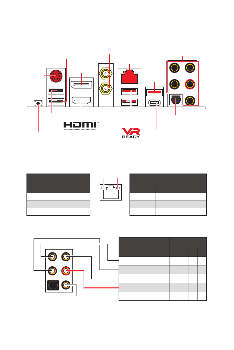
Rear I/O Panel
Flash BIOS
Port
DisplayPort
PS/2
Wi-Fi Antenna
connectors
Audio Ports
LAN
USB 3.2
Gen2
Type-A
USB 2.0 Type-A
USB 3.2 Gen1
Optical S/PDIF-Out
Type-A
Flash BIOS Button
USB 3.2 Gen2 Type-C
y Flash BIOS Port/ Button - Please refer to page 45 for Updating BIOS with Flash BIOS
Button.
LAN Port LED Status Table
Link/ Activity LED
Status Description
Off No link
Yellow Linked
Blinking Data activity
Speed LED
Status Description
Off 10 Mbps connection
Green 100 Mbps connection
Orange 1 Gbps connection
Audio Ports Configuration
Audio Ports
Center/ Subwoofer Out ● ●
Rear Speaker Out ● ● ●
Line-In/ Side Speaker Out ●
Line-Out/ Front Speaker Out ● ● ● ●
Mic In
(●: connected, Blank: empty)
Channel
2 4 6 8
Rear I/O Panel
24
Page 25
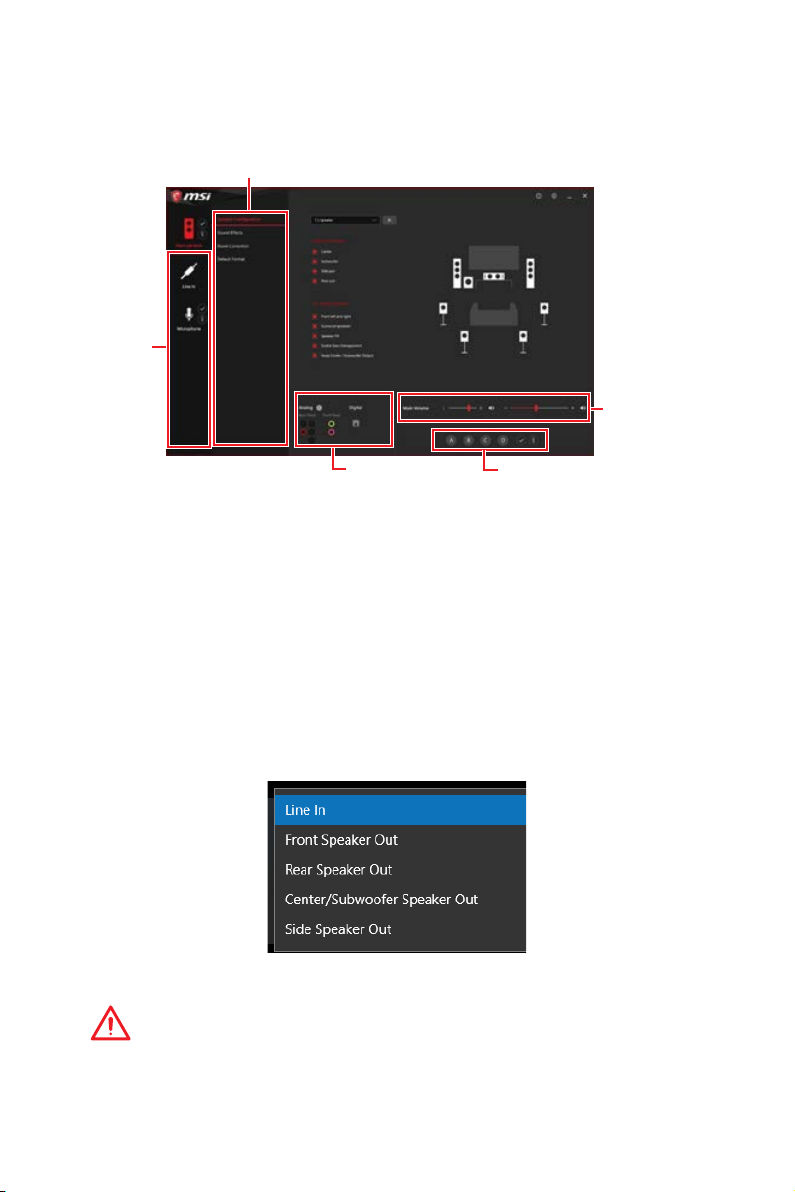
Realtek Audio Console
After Realtek Audio Console is installed. You can use it to change sound settings to get
better sound experience.
Application Enhancement
Device
Selection
Main Volume
Jack Status
Profiles
y Device Selection - allows you to select a audio output source to change the related
options. The check sign indicates the devices as default.
y Application Enhancement - the array of options will provide you a complete guidance
of anticipated sound effect for both output and input device.
y Main Volume - controls the volume or balance the right/left side of the speakers that
you plugged in front or rear panel by adjust the bar.
y Profiles - toggles between profiles.
y Jack Status - depicts all render and capture devices currently connected with your
computer.
Auto popup dialog
When you plug into a device at an audio jack, a dialogue window will pop up asking you
which device is current connected.
Each jack corresponds to its default setting as shown on the next page.
Important
The pictures above for reference only and may vary from the product you purchased.
Rear I/O Panel
25
Page 26
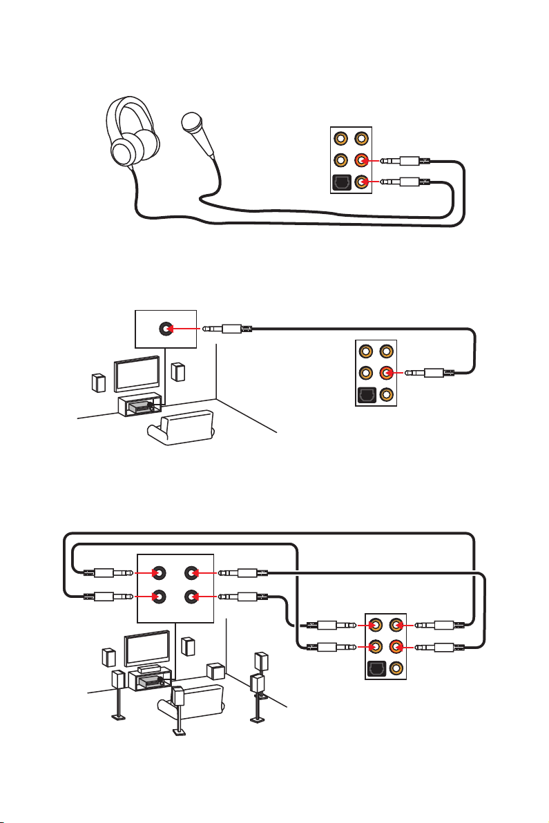
Audio jacks to headphone and microphone diagram
Audio jacks to stereo speakers diagram
AUDIO INPUT
Audio jacks to 7.1-channel speakers diagram
AUDIO INPUT
Rear Front
Side Center/
Subwoofer
Rear I/O Panel
26
Page 27
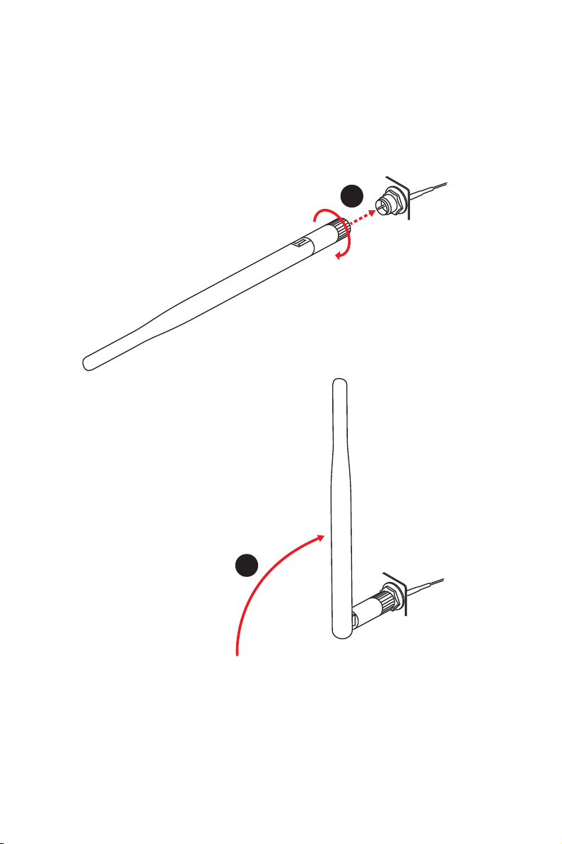
Installing antennas
1. Screw the antennas tight to the antenna connectors as shown below.
2. Orient the antennas.
1
2
Rear I/O Panel
27
Page 28
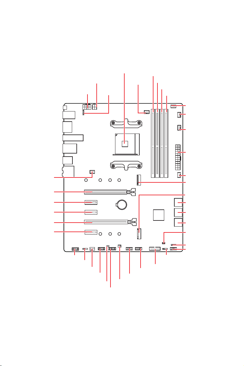
Overview of Components
Processor
Socket
CPU_PWR2
CPU_PWR1
JRGB2
CPU_FAN1
DIMMA1
DIMMA2
DIMMB1
DIMMB2
JCORSAIR1
PUMP_FAN1
SYS_FAN4
ATX_PWR1
SYS_FAN1
PCI_E1
PCI_E2
PCI_E3
PCI_E4
PCI_E5
JAUD1
JRGB1
SYS_FAN2
JCOM1
JCI1
JTPM1
BAT1
JUSB1
JPWRLED1
JUSB2
JUSB3
JRAINBOW1
SYS_FAN3
M2_1
M2_2
SATA▼5▲6
SATA▼3▲4
SATA▼1▲2
JBAT1
JFP2
JFP1
Overview of Components
28
Page 29

Component Contents
Port Name Port Type Page
CPU_FAN1, PUMP_FAN1, SYS_FAN1~4 Fan Connectors 37
CPU_PWR1~2, ATX_PWR1 Power Connectors 35
DIMMA1, DIMMA2, DIMMB1, DIMMB2 DIMM Slots 31
JAUD1 Front Audio Connector 37
JBAT1 Clear CMOS Jumper 39
JCI1 Chassis Intrusion Connector 38
JCOM1 Serial Port Connector 38
JCORSAIR1 CORSAIR Connector 41
JFP1, JFP2 Front Panel Connectors 34
JRGB1~2, JRAINBOW1 RGB LED connectors 40
JTPM1 TPM Module Connector 39
JUSB1~2 USB 2.0 Connectors 36
JUSB3 USB 3.2 Gen1 Connector 36
M2_1~2 M.2 Slots (Key M) 33
PCI_E1~5 PCIe Expansion Slots 32
Processor Socket AM4 socket 30
SATA1~6 SATA 6Gb/s Connectors 34
Overview of Components
29
Page 30
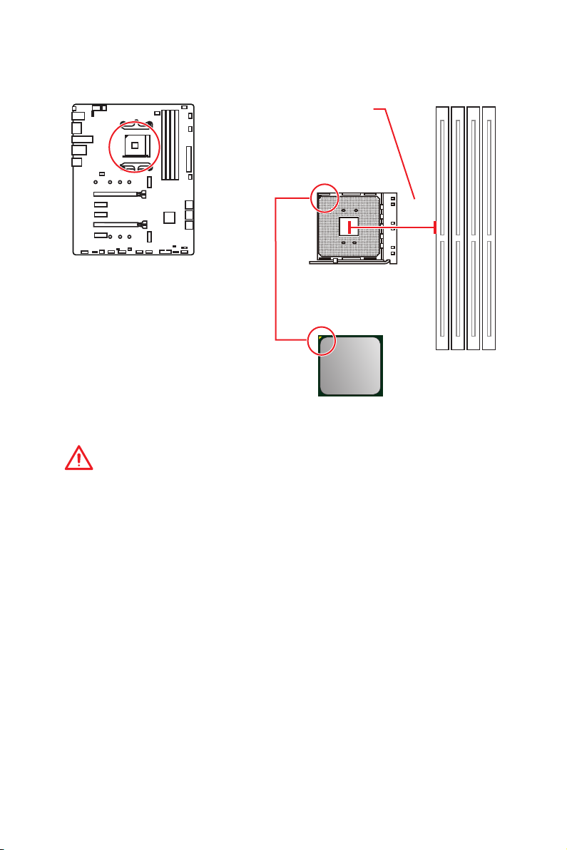
Processor Socket
Distance from the center of the
CPU to the nearest DIMM slot.
53.893
mm
Introduction to the AM4 CPU
The surface of the AM4 CPU has a
yellow triangle to assist in correctly
lining up the CPU for motherboard
placement. The yellow triangle is
the Pin 1 indicator.
Important
y
When changing the processor, the system configuration could be cleared and reset
BIOS to default values, due to the AM4 processor’s architecture.
y
Always unplug the power cord from the power outlet before installing or removing
the CPU.
y
When installing a CPU, always remember to install a CPU heatsink. A CPU heatsink
is necessary to prevent overheating and maintain system stability.
y
Confirm that the CPU heatsink has formed a tight seal with the CPU before booting
your system.
y
Overheating can seriously damage the CPU and motherboard. Always make sure
the cooling fans work properly to protect the CPU from overheating. Be sure to apply
an even layer of thermal paste (or thermal tape) between the CPU and the heatsink to
enhance heat dissipation.
y
If you purchased a separate CPU and heatsink/ cooler, Please refer to the
documentation in the heatsink/ cooler package for more details about installation.
y
This motherboard is designed to support overclocking. Before attempting to
overclock, please make sure that all other system components can tolerate
overclocking. Any attempt to operate beyond product specifications is not
recommended. MSI
operation beyond product specifications.
®
does not guarantee the damages or risks caused by inadequate
Overview of Components
30
Page 31

DIMM Slots
DIMMA1 DIMMB1
Channel A Channel B
DIMMA2 DIMMB2
Memory module installation recommendation
DIMMB2 DIMMB2
DIMMA2 DIMMA2 DIMMA2
DIMMB1
DIMMA1
Important
y
Always insert memory modules in the DIMMA2 slot first.
y
Due to chipset resource usage, the available capacity of memory will be a little less
than the amount of installed.
y
Based on processor specification, the Memory DIMM voltage below 1.35V is
suggested to protect the processor.
y
Some memory modules may operate at a lower frequency than the marked value
when overclocking due to the memory frequency operates dependent on its Serial
Presence Detect (SPD). Go to BIOS and find the DRAM Frequency to set the memory
frequency if you want to operate the memory at the marked or at a higher frequency.
y
It is recommended to use a more efficient memory cooling system for full DIMMs
installation or overclocking.
y
The stability and compatibility of installed memory module depend on installed CPU
and devices when overclocking.
y
Due to AM4 processor/memory controller official specification limitation, the
frequency of memory modules may operate lower than the marked value under the
default state. Please refer www.msi.com for more information on compatible memory.
Overview of Components
31
Page 32

PCI_E1~5: PCIe Expansion Slots
PCI_E1: PCIe 3.0 x16*/ PCIe 3.0 x8**/ PCIe 3.0 x4***
BAT1
* For 1st, 2nd and 3rd Gen AMD Ryzen™ processors
** For Ryzen™ with Radeon™ Vega Graphics and 2nd Gen AMD Ryzen™ with Radeon™
Graphics processors
*** For Athlon™ with Radeon Vega Graphics processors
Important
y
If you install a large and heavy graphics card, you need to use a tool such as MSI
Gaming Series Graphics Card Bolster to support its weight to prevent deformation of
the slot.
y
For a single PCIe x16 expansion card installation with optimum performance, using
the PCI_E1 slot is recommended.
y
When adding or removing expansion cards, always turn off the power supply and
unplug the power supply power cable from the power outlet. Read the expansion
card’s documentation to check for any necessary additional hardware or software
changes.
y
PCI_E2, PCI_E3, PCI_E4, PCI_E5 slot will be unavailable when installing M.2 PCIe
SSD in M2_2 slot.
y
PCI_E4 will run x1 speed when installing devices in any PCIe 2.0x1 slot.
PCIe bandwidth of Multiple graphics cards
PCI_E2: PCIe 2.0 x1
PCI_E3: PCIe 2.0 x1
PCI_E4: PCIe 2.0 x4
PCI_E5: PCIe 2.0 x1
Slot Single 2-Way
/1
PCI_E1 (CPU)
3.0 x16*
3.0 x8*
3.0 x4*
or
/2
or
/3
3.0 x16*/1
or
3.0 x8*
or
3.0 x4*
PCI_E2 (PCH) 2.0 x1 ―
PCI_E3 (PCH) 2.0 x1 ―
PCI_E4 (PCH) 2.0 x1 2.0 x4*
PCI_E5 (PCH) 2.0 x1 ―
M2_1 (CPU) 3.0 x4 3.0 x4
M2_2 (PCH) ― ―
(─: unavailable, *: graphics card,
2
: for Ryzen™ with Radeon™ Vega Graphics and 2nd Gen AMD Ryzen™ with Radeon™
Graphics processors,
Overview of Components
32
3
: for Athlon™ with Radeon Vega Graphics processors)
1
: for 1st, 2nd and 3rd Gen AMD Ryzen™ processors,
/2
/3
Page 33

M2_1~2: M.2 Slots (Key M)
M2_1
M2_2
Installing M.2 SSD
1. Move the position of the standoffs
according to your M.2 SSDs length if
need.
2. Insert your M.2 SSD into the M.2 slot at a
30-degree angle.
Video Demonstration
Watch the video to learn how to use M.2
Shield.
https://youtu.be/NwtQBpkUazs
3. Secure the M.2 SSD in place with
the supplied M.2 screw.
3
Supplied
M.2 screw
2
30º30º
1
Standoff
Using M.2 shield
We provide the M.2 shield on the M2_1 slot to help dissipate
heat away from the M.2 SSD. Before installing the M.2
SSD for the first time, you need to remove the screw, lift
the cover and remove the protective film and the round
rubber from the thermal pad.
Important
If you don’t need the M.2 shield, you can remove it.
Overview of Components
33
Page 34

SATA1~6: SATA 6Gb/s Connectors
These connectors are SATA 6Gb/s interface ports. Each connector can connect to one
SATA device.
SATA6
SATA5
SATA4
SATA3
SATA2
SATA1
Important
y
Please do not fold the SATA cable at a 90-degree angle. Data loss may result during
transmission otherwise.
y
SATA cables have identical plugs on either sides of the cable. However, it is
recommended that the flat connector be connected to the motherboard for space
saving purposes.
y
SATA5 and SATA6 ports will be unavailable when installing a M.2 device in M2_1 slot.
JFP1, JFP2: Front Panel Connectors
These connectors connect to the switches and LEDs on the front panel.
1
JFP2
Overview of Components
34
Power LED
JFP1
Power Switch
+++-
--
2 10
1
-
+
9
Reserved
HDD LED Reset Switch
1 HDD LED + 2 Power LED +
3 HDD LED - 4 Power LED -
5 Reset Switch 6 Power Switch
7 Reset Switch 8 Power Switch
9 Reserved 10 No Pin
Buzzer
++-
Speaker
1 Speaker - 2 Buzzer +
3 Buzzer - 4 Speaker +
Page 35

CPU_PWR1~2, ATX_PWR1: Power Connectors
These connectors allow you to connect an ATX power supply.
4
2 1
5
3
CPU_PWR2
CPU_PWR1
8
4 1
1 Ground 5 +12V
2 Ground 6 +12V
3 Ground 7 +12V
4 Ground 8 +12V
1 Ground 3 +12V
2 Ground 4 +12V
1 +3.3V 13 +3.3V
2 +3.3V 14 -12V
3 Ground 15 Ground
24
12
ATX_PWR1
131
4 +5V 16 PS-ON#
5 Ground 17 Ground
6 +5V 18 Ground
7 Ground 19 Ground
8 PWR OK 20 Res
9 5VSB 21 +5V
10 +12V 22 +5V
11 +12V 23 +5V
12 +3.3V 24 Ground
Important
Make sure that all the power cables are securely connected to a proper ATX power
supply to ensure stable operation of the motherboard.
Overview of Components
35
Page 36

JUSB1~2: USB 2.0 Connectors
These connectors allow you to connect USB 2.0 ports on the front panel.
2 10
1
9
1 VCC 2 VCC
3 USB0- 4 USB1-
5 USB0+ 6 USB1+
7 Ground 8 Ground
9 No Pin 10 NC
Important
y
Note that the VCC and Ground pins must be connected correctly to avoid possible
damage.
y
In order to recharge your iPad,iPhone and iPod through USB ports, please install
®
MSI
SUPER CHARGER utility.
JUSB3: USB 3.2 Gen1 Connector
This connector allows you to connect USB 3.2 Gen1 ports on the front panel.
1
20
1 Power 11 USB2.0+
2 USB3_RX_DN 12 USB2.0-
3 USB3_RX_DP 13 Ground
4 Ground 14 USB3_TX_C_DP
5 USB3_TX_C_DN 15 USB3_TX_C_DN
6 USB3_TX_C_DP 16 Ground
7 Ground 17 USB3_RX_DP
8 USB2.0- 18 USB3_RX_DN
9 USB2.0+ 19 Power
10 NC 20 No Pin
10
11
Important
Note that the Power and Ground pins must be connected correctly to avoid possible
damage.
Overview of Components
36
Page 37

CPU_FAN1, PUMP_FAN1, SYS_FAN1~4: Fan Connectors
Fan connectors can be classified as PWM (Pulse Width Modulation) Mode or DC Mode.
PWM Mode fan connectors provide constant 12V output and adjust fan speed with
speed control signal. DC Mode fan connectors control fan speed by changing voltage.
When you plug a 3-pin (Non-PWM) fan to a fan connector in PWM mode, the fan speed
will always maintain at 100%, which might create a lot of noise. You can follow the
instruction below to adjust the fan connector to PWM or DC Mode. However, with autodetection mode fan connectors, the system will auto detect the fan mode.
1
1
CPU_FAN1
(Default : Auto-detection
Mode)
Default DC Mode fan connectors
1
SYS_FAN1/ SYS_FAN2
Pin definition of fan connectors
PWM Mode pin definition
1 Ground 2 +12V
3 Sense 4 Speed Control Signal
1 Ground 2 Voltage Control
3 Sense 4 NC
Important
y
You can switch between PWM mode and DC mode and adjust fan speed in BIOS >
HARDWARE MONITOR.
y
Make sure fans are working properly after switching the PWM/ DC mode.
PUMP_FAN1
(Default : PWM Mode)
1
SYS_FAN3/ SYS_FAN4
DC Mode pin definition
JAUD1: Front Audio Connector
This connector allows you to connect audio jacks on the front panel.
2 10
1
9
1 MIC L 2 Ground
3 MIC R 4 NC
5 Head Phone R 6 MIC Detection
7 SENSE_SEND 8 No Pin
9 Head Phone L 10 Head Phone Detection
Overview of Components
37
Page 38

JCI1: Chassis Intrusion Connector
This connector allows you to connect the chassis intrusion switch cable.
Normal
(default)
Trigger the chassis
intrusion event
Using chassis intrusion detector
1. Connect the JCI1 connector to the chassis intrusion switch/ sensor on the chassis.
2. Close the chassis cover.
3. Go to BIOS > SETTINGS > Security > Chassis Intrusion Configuration.
4. Set Chassis Intrusion to Enabled.
5. Press F10 to save and exit and then press the Enter key to select Yes.
6. Once the chassis cover is opened again, a warning message will be displayed on
screen when the computer is turned on.
Resetting the chassis intrusion warning
1. Go to BIOS > SETTINGS > Security > Chassis Intrusion Configuration.
2. Set Chassis Intrusion to Reset.
3. Press F10 to save and exit and then press the Enter key to select Yes.
JCOM1: Serial Port Connector
This connector allows you to connect the optional serial port with bracket.
2 10
Overview of Components
38
1
9
1 DCD 2 SIN
3 SOUT 4 DTR
5 Ground 6 DSR
7 RTS 8 CTS
9 RI 10 No Pin
Page 39

JTPM1: TPM Module Connector
This connector is for TPM (Trusted Platform Module). Please refer to the TPM security
platform manual for more details and usages.
2 14
1
1 LPC Clock 2 3V Standby power
3 LPC Reset 4 3.3V Power
5 LPC address & data pin0 6 Serial IRQ
7 LPC address & data pin1 8 5V Power
9 LPC address & data pin2 10 No Pin
11 LPC address & data pin3 12 Ground
13 LPC Frame 14 Ground
13
JBAT1: Clear CMOS (Reset BIOS) Jumper
There is CMOS memory onboard that is external powered from a battery located on
the motherboard to save system configuration data. If you want to clear the system
configuration, set the jumpers to clear the CMOS memory.
Keep Data
(default)
Clear CMOS/
Reset BIOS
Resetting BIOS to default values
1. Power off the computer and unplug the power cord.
2. Use a jumper cap to short JBAT1 for about 5-10 seconds.
3. Remove the jumper cap from JBAT1.
4. Plug the power cord and Power on the computer.
Overview of Components
39
Page 40

JRGB1~2, JRAINBOW1: RGB LED connectors
The JRGB1/2 connectors allow you to connect the 5050 RGB LED strips 12V. The
JRAINBOW1 connector allows you to connect the WS2812B Individually Addressable
RGB LED strips 5V.
JRGB2
1
1 +12V 2 G
3 R 4 B
JRGB1/2
JRGB1
JRAINBOW1
1
JRGB1/2
Extension cable
5050 RGB LED strips 12V
JRAINBOW1
1
1 +5V 2 Data
3 No Pin 4 Ground
1
JRAINBOW1
Rainbow RGB LED
extension cable
WS2812B Individually
Addressable RGB LED strips 5V
CAUTION
Do not connect the wrong type of LED strips. The JRGB1/JRGB2 connector and the
JRAINBOW1 connector provide different voltages, and connecting the 5V LED strip to
the JRGB1/JRGB2 connector will result in damage to the LED strip.
Important
y
The JRGB1/ JRGB2 connector supports up to 2 meters continuous 5050 RGB LED
strips (12V/G/R/B) with the maximum power rating of 3A (12V).
y
The JRAINBOW1 connector supports up to 72 LEDs WS2812B Individually
Addressable RGB LED strips (5V/Data/Ground) with the maximum power rating of 3A
(5V).
y
Always turn off the power supply and unplug the power cord from the power outlet
before installing or removing the RGB LED strip.
y
Please use MSI’s software to control the extended LED strip.
Overview of Components
40
Page 41

JCORSAIR1: CORSAIR Connector
The JCORSAIR1 connector allows you to connect the CORSAIR Individually
Addressable Lighting PRO RGB LED strips 5V or CORSAIR RGB fans with the CORSAIR
fan hub. Once all items are connected properly, you can control the CORSAIR RGB LED
strips and fans with MSI's software.
1
JCORSAIR1
1 +5V 2 Data
3 Ground
CORSAIR RGB Fan Connection
CORSAIR RGB fan
1
2
3
CORSAIR RGB LED Extension Cable
CORSAIR fan hub
Connect the SATA Power
connector to power
supply.
6
5
4
JCORSAIR1 connector
Important
Fans must start at 1 and continue in series. 1 > 2 > 3 > 4 > 5 > 6. Any fan not connected
in series will break communication and the RGB LED lighting function will not work.
CORSAIR Lighting PRO RGB LED Strip Connection
JCORSAIR1 connector
Important
y
Quantity of RGB Fans or Lighting PRO RGB LED strips supported may differ between
models. Please refer to the motherboard specification.
y
CORSAIR RGB Fan and CORSAIR Lighting PRO RGB LED strip can’t be used at the
same time.
Overview of Components
41
Page 42

EZ Debug LED
These LEDs indicate the debug status of the motherboard.
CPU - indicates CPU is not detected or fail.
DRAM - indicates DRAM is not detected or fail.
VGA - indicates GPU is not detected or fail.
BOOT - indicates the booting device is not detected
or fail.
Overview of Components
42
Page 43

BIOS Setup
The default settings offer the optimal performance for system stability in normal
conditions. You should always keep the default settings to avoid possible system
damage or failure booting unless you are familiar with BIOS.
Important
y
BIOS items are continuously update for better system performance. Therefore, the
description may be slightly different from the latest BIOS and should be for reference
only. You could also refer to the HELP information panel for BIOS item description.
y
The pictures in this chapter are for reference only and may vary from the product you
purchased.
y
The BIOS items will vary with the processor.
Entering BIOS Setup
Press Delete key, when the Press DEL key to enter Setup Menu, F11 to enter Boot
Menu message appears on the screen during the boot process.
Function key
F1: General Help list
F2: Add/ Remove a favorite item
F3: Enter Favorites menu
F4: Enter CPU Specifications menu
F5: Enter Memory-Z menu
F6: Load optimized defaults
F7: Switch between Advanced mode and EZ mode
F8: Load Overclocking Profile
F9: Save Overclocking Profile
F10: Save Change and Reset*
F12: Take a screenshot and save it to USB flash drive (FAT/ FAT32 format only).
Ctrl+F: Enter Search page
* When you press F10, a confirmation window appears and it provides the modification
information. Select between Yes or No to confirm your choice.
BIOS Setup
43
Page 44

Resetting BIOS
You might need to restore the default BIOS setting to solve certain problems. There are
several ways to reset BIOS:
y Go to BIOS and press F6 to load optimized defaults.
y Short the Clear CMOS jumper on the motherboard.
Important
Be sure the computer is off before clearing CMOS data. Please refer to the Clear
CMOS jumper section for resetting BIOS.
Updating BIOS
Updating BIOS with M-FLASH
Before updating:
Please download the latest BIOS file that matches your motherboard model from MSI
website. And then save the BIOS file into the USB flash drive.
Updating BIOS:
1. Press Del key to enter the BIOS Setup during POST.
2. Insert the USB flash drive that contains the update file into the computer.
3. Select the M-FLASH tab and click on Yes to reboot the system and enter the flash
mode.
4. Select a BIOS file to perform the BIOS update process.
5. After the flashing process is 100% completed, the system will reboot
automatically.
Updating the BIOS with Live Update 6
Before updating:
Make sure the LAN driver is already installed and the internet connection is set
properly.
Updating BIOS:
1. Install and launch MSI LIVE UPDATE 6.
2. Select BIOS Update.
3. Click on Scan button.
4. Click on Download icon to download and install the latest BIOS file.
5. Click Next and choose In Windows mode. And then click Next and Start to start
updating BIOS.
6. After the flashing process is 100% completed, the system will restart
automatically.
44
BIOS Setup
Page 45

Updating BIOS with Flash BIOS Button
Before updating:
Please download the latest BIOS file that matches your motherboard model from MSI
website and rename the BIOS file to MSI.ROM. And then, save the MSI.ROM file to the
root of USB flash drive.
Important
Only the FAT32 format USB flash drive supports updating BIOS by Flash BIOS Button.
1. Connect power supply to CPU_PWR1 and ATX_PWR1. (No other components are
necessary but power supply.)
2. Plug the USB flash drive that contains the MSI.ROM file into the Flash BIOS Button
port on rear I/O panel.
3. Press the Flash BIOS Button to flash BIOS, and the LED next to the button starts
flashing.
4. After the flashing BIOS process is 100% completed, the LED would be off
simultaneously.
®
BIOS Setup
45
Page 46

EZ Mode
At EZ mode, it provides the basic system information and allows you to configure the
basic setting. To configure the advanced BIOS settings, please enter the Advanced
Mode by pressing the Setup Mode switch or F7 function key.
A-XMP switch
GAME BOOST
switch
Information
display
M-Flash
Favorites
Hardware
Monitor
Setup Mode switch
y GAME BOOST switch - click on it to toggle the GAME BOOST for OC.
Important
Please don’t make any changes in OC menu and don’t load defaults to keep the
optimal performance and system stability after activating the GAME BOOST function.
y A-XMP switch (optional) - click on the inner circle to enable/ disable the A-XMP.
Switch the outer circle to select the memory profile if any. This switch will only be
available if the installed processor and memory modules support XMP function.
y Setup Mode switch - press this tab or the F7 key to switch between Advanced mode
and EZ mode.
y Screenshot - click on this tab or the F12 key to take a screenshot and save it to USB
flash drive (FAT/ FAT32 format only).
y Search - click on this tab or the Ctrl+F keys and the search page will show. It allows
you to search by BIOS item name, enter the item name to find the item listing. Move
the mouse over a blank space and right click the mouse to exit search page.
Important
In search page, only the F6, F10 and F12 function keys are available.
y Language - allows you to select the language of BIOS setup.
y System information - shows the CPU/ DDR speed, CPU/ MB temperature, MB/ CPU
type, memory size, CPU/ DDR voltage, BIOS version and build date.
y Boot device priority bar - you can move the device icons to change the boot priority.
The boot priority from high to low is left to right.
Screenshot
Search
Language
System
information
Boot device
priority bar
Function
buttons
46
BIOS Setup
Page 47

y Information display - click on the CPU, Memory, Storage, Fan Info and Help buttons
on left side to display related information.
y Function buttons - enable or disable the LAN Option ROM, HD audio controller,
AHCI/ RAID, CPU Fan Fail Warning Control, Windows 10 WHQL Support and BIOS Log
Review by clicking on their respective button.
y M-Flash - click on this button to display the M-Flash menu that provides the way to
update BIOS with a USB flash drive.
y Hardware Monitor - click on this button to display the Hardware Monitor menu that
allows you to manually control the fan speed by percentage.
y Favorites menu - press the F3 key to enter Favorites menu. It allows you to create
personal BIOS menu where you can save and access favorite/ frequently-used BIOS
setting items.
Default HomePage - allows you to select a BIOS menu (e.g. SETTINGS, OC...,etc)
as the BIOS home page.
Favorite1~5 - allows you to add the frequently-used/ favorite BIOS setting items
in one page.
To add a BIOS item to a favorite page (Favorite 1~5)
1. Move the mouse over a BIOS item not only on BIOS menu but also on search
page.
2. Right-click or press F2 key.
3. Choose a favorite page and click on OK.
To delete a BIOS item from favorite page
1. Move the mouse over a BIOS item on favorite page (Favorite 1~5)
2. Right-click or press F2 key.
3. Choose Delete and click on OK.
BIOS Setup
47
Page 48

Advanced Mode
Press Setup Mode switch or F7 function key can switch between EZ Mode and
Advanced Mode in BIOS setup.
A-XMP switch
GAME BOOST
switch
Setup Mode switch
Screenshot
Search
Language
System
information
Boot device
priority bar
BIOS menu
selection
Menu display
BIOS menu
selection
y BIOS menu selection - the following options are available:
SETTINGS - allows you to specify the parameters for chipset and boot devices.
OC - allows you to adjust the frequency and voltage. Increasing the frequency may
get better performance.
M-FLASH - provides the way to update BIOS with a USB flash drive.
OC PROFILE - allows you to manage overclocking profiles.
HARDWARE MONITOR - allows you to set the speeds of fans and monitor voltages
of system.
BOARD EXPLORER - provides the information of installed devices on this
motherboard.
y Menu display - provides BIOS setting items and information to be configured.
48
BIOS Setup
Page 49

SETTINGS
System Status
f System Date
Sets the system date. Use tab key to switch between date elements.
The format is <day> <month> <date> <year>.
<day> Day of the week, from Sun to Sat, determined by BIOS. Read-only.
<month> The month from Jan. through Dec.
<date> The date from 1 to 31 can be keyed by numeric function keys.
<year> The year can be adjusted by users.
f System Time
Sets the system time. Use tab key to switch between time elements.
The time format is <hour> <minute> <second>.
f SATA PortX
Shows the information of connected SATA device.
Important
If the connected SATA device is not displayed, turn off computer and re-check SATA
cable and power cable connections of the device and motherboard.
f System Information
Shows detailed system information, including CPU type, BIOS version, and Memory
(read only).
f DMI Information
Shows system information, desktop Board Information and chassis Information. (Read
only).
Advanced
f PCI Subsystem Settings
Sets PCI, PCI express interface protocol and latency timer. Press Enter to enter the
sub-menu.
BIOS Setup
49
Page 50

fAbove 4G memory/ Crypto Currency mining [Disabled]
Enables or disables 64-bit capable devices to be decoded in above 4G address
space. It is only available if the system supports 64-bit PCI decoding.
[Enabled] Allows you to utilize more than 4x GPUs.
[Disabled] Disables this function.
fPCIe SlotX Lanes Configuration
PCIe lanes configuration is for MSI M.2 Xpander / MSI M.2 Xpander-Z / Other M.2
PCIe storage card. The options in this item will vary with the installed processor.
f ACPI Settings
Sets ACPI parameters of onboard power LED behaviors. Press Enter to enter the submenu.
fPower LED [Blinking]
Sets shining behaviors of the onboard Power LED.
[Dual Color] The power LED turns to another color to indicate the S3 state.
[Blinking] The power LED blinks to indicate the S3 state.
fCPU Over Temperature Alert [Auto]
Enables or disables the CPU overheating alert sound and message when CPU
temperature is over 55 and 75 degrees centigrade.
f Integrated Peripherals
Sets integrated peripherals' parameters, such as LAN, HDD, USB and audio. Press
Enter to enter the sub-menu.
fOnboard LAN Controller [Enabled]
Enables or disables the onboard LAN controller.
50
fLAN Option ROM [Disabled]
Enables or disables the legacy network Boot Option ROM for detailed settings. This
item will appear when Onboard LAN Controller is enabled.
[Enabled] Enables the onboard LAN Boot ROM.
[Disabled] Disables the onboard LAN Boot ROM.
fNetwork Stack [Disabled]
Sets UEFI network stack for optimizing IPv4 / IPv6 function. This item is available
when Onboard LAN Controller is Enabled.
[Enabled] Enables UEFI network stack.
[Disabled] Disables UEFI network stack.
fIpv4 PXE Support [Enabled]
When Enabled, the system UEFI network stack will support Ipv4 protocol. This item
will appear when Network Stack is Enabled.
[Enabled] Enables the Ipv4 PXE boot support.
[Disabled] Disables the Ipv4 PXE boot support.
BIOS Setup
Page 51

fIpv6 PXE Support [Enabled]
When Enabled, the system UEFI network stack will support Ipv6 protocol. This item
will appear when Network Stack is enabled.
[Enabled] Enables the Ipv6 PXE boot support.
[Disabled] Disables the Ipv6 PXE boot support.
fSATA Mode [AHCI Mode]
Sets the operation mode of the onboard SATA controller.
[AHCI Mode] Specify the AHCI mode for SATA storage devices. AHCI (Advanced
[RAID Mode] Enables RAID function for SATA storage devices.
fSATAx Hot Plug [Disabled]
Allows user to enable or disable the SATA hot plug support.
[Enabled] Enables hot plug support for the SATA ports.
[Disabled] Disables hot plug support for the SATA ports.
fHD Audio Controller [Enabled]
Enables or disables the onboard High Definition Audio controller.
f Integrated Graphics Configuration (optional)
Adjusts integrated graphics settings for optimum system. Press Enter to enter the
sub-menu.
fInitiate Graphic Adapter [PEG] (optional)
Selects a graphics device as the primary boot device.
[IGD] Integrated Graphics Display.
[PEG] PCI-Express Graphics Device.
fIntegrated Graphics [Auto] (optional)
If set to Force, BIOS will enable the integrated graphics controller.
fUMA Frame Buffer Size [Auto] (optional)
Selects a fixed amount of system memory allocated to the onboard graphics. This
item will be available when Integrated Graphics is enabled.
f USB Configuration
Sets the onboard USB controller and device function. Press Enter to enter the submenu.
Host Controller Interface) offers some advanced features to enhance
the speed and performance of SATA storage device, such as Native
Command Queuing (NCQ) and hot-plugging.
fXHCI Hand-off [Enabled]
Enables or disables XHCI hand-off support for the operating system without XHCI
hand-off feature.
fLegacy USB Support [Enabled]
Sets Legacy USB function support.
[Auto] The system will automatically detect if any USB device is connected
and enable the legacy USB support.
[Enabled] Enable the USB support under legacy mode.
[Disabled] The USB devices will be unavailable under legacy mode.
BIOS Setup
51
Page 52

f Power Management Setup
Sets system Power Management of ErP and AC Power Loss behaviors. Press Enter to
enter the sub-menu.
fErP Ready [Disabled]
Enables or disables the system power consumption according to ErP regulation.
[Enabled] Optimize the system power consumption according to ErP
[Disabled] Disables this function.
fRestore after AC Power Loss [Power Off]
Sets the system behaviors while encountering the AC power loss.
[Power Off] Leaves the system in power off state after restoring AC power.
[Power On] Boot up the system after restoring AC power.
[Last State] Restores the system to the previous state (power on/ power off)
fSystem Power Fault Protection [Disabled]
Enables or disables the system to boot up when detecting abnormal voltage input.
[Enabled] Protect the system from unexpected power operating and remain
[Disabled] Disables this function.
f Windows OS Configuration
Sets Windows detailed configuration and behaviors. Press Enter to enter the submenu.
fWindows 10 WHQL Support [Disabled]
Enables the supports for Windows 10 or disables for other operating systems.
Before enabling this item, make sure all installed devices & utilities (hardware &
software) should meet the Windows 10 requirements.
[Enabled] The system will switch to UEFI mode to meet the Windows
[Disabled] Disables this function.
regulation. It will not support S4 & S5 wake up by USB, PCI and PCIe
devices.
before AC power loss.
the shut down status.
requirement.
fInternal GOP Configuration
Manages the onboard Graphics Output Protocol (GOP). Press Enter to enter
the sub-menu. This sub-menu will appear when Windows 10 WHQL Support is
enabled.
fSecure Boot
Sets the Windows secure boot to prevent the unauthorized accessing. Press Enter
to enter the sub-menu. This sub-menu will appear when Windows 10 WHQL
Support is enabled.
f Wake Up Event Setup
Sets system wake up behaviors for different sleep modes. Press Enter to enter the
sub-menu.
BIOS Setup
52
Page 53

fWake Up Event By [BIOS]
Selects the wake up event by BIOS or operating system.
[BIOS] Activates the following items, set wake up events of these items.
[OS] The wake up events will be defined by OS.
fResume By RTC Alarm [Disabled]
Disables or enables the system wake up by RTC Alarm.
[Enabled] Enables the system to boot up on a scheduled time/ date.
[Disabled] Disables this function.
fDate (of month) Alarm/ Time (hh:mm:ss) Alarm
Sets RTC alarm date/ Time. If Resume By RTC Alarm is set to [Enabled], the system
will automatically resume (boot up) on a specified date/hour/minute/second in
these fields (using the + and - keys to select the date & time settings).
fResume By PCI-E Device [Disabled]
Enables or disables the wake up function of installed PCI-E expansion cards,
integrated LAN controllers or USB devices which are supported by third party
integrated chips.
[Enabled] Enables the system to be awakened from the power saving modes
[Disabled] Disables this function.
fResume by USB Device [Disabled]
Disables or enables system wake up from S3/S4 by USB device.
[Enabled] Enables the system to be awakened from sleep state when activity of
[Disabled] Disables this function.
fResume From S3/S4/S5 by PS/2 Mouse [Disabled]
Enables or disables the system wake up by PS/2 mouse.
[Enabled] Enables the system to be awakened from S3/ S4/ S5 state when
[Disabled] Disables this function.
when activity or input signal of PCIe device is detected.
USB device is detected.
activity of PS/2 mouse is detected.
fResume From S3/S4/S5 by PS/2 Keyboard [Disabled]
Enables or disables the system wake up by PS/2 keyboard.
[Any Key] Enables the system to be awakened from S3/ S4/ S5 state when
activity of any key on PS/2 keyboard is detected.
[Hot Key] Enables the system to be awakened from S3/ S4/ S5 state when
activity of hot key on PS/2 keyboard is detected.
[Disabled] Disables this function.
fHot Key [Ctrl+Space]
Selects a combination of keys as a hot key to wake the system. This item appears
when you set the Resume From S3/S4/S5 by PS/2 Keyboard to Hot Key.
BIOS Setup
53
Page 54

f Secure Erase+
Enables or disables Secure Erase+ function. Secure Erase+ is the best way to
effectively wipe all data from a SSD. Please note that data of SSD will be erased after
enabling Secure Erase+.
f Intel (R) I211 Gigabit
Shows driver information and configuration of the Ethernet controller parameter.
Boot
Sets the sequence of system boot devices.
f Full Screen Logo Display [Enabled]
Enables or disables to show the full screen logo while system POST.
[Enabled] Shows the logo in full screen.
[Disabled] Shows the POST messages.
f Bootup NumLock State [On]
Select the keyboard NumLock state upon bootup.
f Info Block effect [Unlock]
Sets the state of Help information block.
[Unlock] Sliding effect.
[Lock] Fix the Help information block on the screen.
f AUTO CLR_CMOS [Disabled]
Enables or disables the CMOS data to be resumed automatically when the system
cannot boot to OS and reboot repeatedly.
f Boot Mode Select [LEGACY+UEFI]
Sets the system boot mode from legacy or UEFI architecture depending on OS
installation requirement. This item will become un-selectable and will be configured
automatically by BIOS when Windows 10 WHQL Support is enabled.
[UEFI] Enables UEFI BIOS boot mode support only.
[LEGACY+UEFI] Enables both Legacy BIOS boot mode and UEFI BIOS boot
f FIXED BOOT ORDER Priorities
Sets device priority for system boot.
f Boot Option Priorities
These items are used to prioritize the installed boot devices.
mode.
Security
f Administrator Password
Sets administrator password for system security. User has full rights to change the
BIOS items with administrator password. After setting the administrator password, the
state of this item will show Installed.
BIOS Setup
54
Page 55

f User Password
Sets User Password for system security. User has limited rights to change the BIOS
items with user password. This item will be available when administrator password is
set. After setting the user password, the state of this item will show Installed.
f Password Check [Setup]
Selects a condition that will request the password.
[Setup] A password will be requested for entering the BIOS Setup.
[Boot] A password will be requested for booting the system.
f Password Clear [Enabled]
Enables or disables the clear CMOS behavior to clear a set password.
[Enabled] The password will be erased after clear CMOS.
[Disabled] The password will always be kept.
Important
When selecting the Administrator / User Password items, a password box will appear
on the screen. Type the password then press Enter. The password typed now will
replace any previous set password from CMOS memory. You will be prompted to
confirm the password. You may also press Esc key to abort the selection.
To clear a set password, press Enter when you are prompted to enter a new password.
A message will confirm the password is being disabled. Once the password is disabled,
you can enter the setup and OS without authorization.
f Trusted Computing
Sets TPM (Trusted Platform Module) function.
fSecurity Device Support [Disabled]
Enables or disables the TPM function to build the endorsement key for accessing
the system.
fAMD fTPM switch [AMD CPU fTPM]
Selects TPM device. This item will appear when Security Device Support is
enabled.
[AMD CPU fTPM] Select it for AMD Firmware TPM.
[AMD CPU fTPM Disabled] Select it for Discrete TPM.
fDevice Select [Auto]
Sets the version of the TPM device. The version must be identical with the device.
Sets to Auto, system will detect the TPM 2.0 or TPM 1.2 model automatically.
f Chassis Intrusion Configuration
Press Enter to enter the sub-menu.
BIOS Setup
55
Page 56

fChassis Intrusion [Disabled]
Enables or disables recording messages while the chassis is opened. This function
is ready for the chassis equips a chassis intrusion switch.
[Enabled] Once the chassis is opened, the system will record and issue a
[Reset] Clear the warning message. After clearing the message, please
[Disabled] Disables this funcion.
warning message.
return to Enabled or Disabled.
Save & Exit
f Discard Changes and Exit
Exit BIOS setup without saving any change.
f Save Changes and Reboot
Save all changes and reboot the system.
f Save Changes
Save current changes.
f Discard Changes
Discard all changes and restore to the previous values.
f Restore Defaults
Restore or load all default values.
f Boot Override
The installed boot-able devices will appear on this menu, you can select one of them to
be the boot device.
56
BIOS Setup
Page 57

OC
Important
y
Overclocking your PC manually is only recommended for advanced users.
y
Overclocking is not guaranteed, and if done improperly, it could void your warranty or
severely damage your hardware.
y
If you are unfamiliar with overclocking, we advise you to use GAME BOOST function
for easy overclocking.
y
The BIOS items in OC menu will vary with the processor.
f OC Explore Mode [Normal]
Enables or disables to show the normal or expert version of OC settings.
[Normal] Provides the regular OC settings in BIOS setup.
[Expert] Provides the advanced OC settings for OC expert to configure in BIOS
Note: We use * as the symbol for the OC settings of Expert mode.
setup.
f CPU Ratio [Auto]
Sets the CPU ratio that is used to determine CPU clock speed. This item can only be
changed if the processor supports this function.
f Core Performance Boost [Auto]
Enables or disables the Core Performance Boost (CPB). This item appears when the
installed CPU supports this function.
f Downcore Control [Auto] (optional)
Sets the number of processor cores to be used. This item appears when the installed
CPU supports this function.
f A-XMP [Disabled]
Please enable A-XMP or select a profile of memory module for overclocking the
memory. This item will be available when the installed processor, memory modules
and motherboard support this function.
f DRAM Frequency [Auto]
Sets the DRAM frequency. Please note the overclocking behavior is not guaranteed.
BIOS Setup
57
Page 58

f Adjusted DRAM Frequency
Shows the adjusted DRAM frequency. Read-only.
f Advanced DRAM Configuration
Press Enter to enter the sub-menu. User can set the memory timing for each/ all
memory channel. The system may become unstable or unbootable after changing
memory timing. If it occurs, please clear the CMOS data and restore the default
settings. (Refer to the Clear CMOS jumper section to clear the CMOS data, and enter
the BIOS to load the default settings.)
f DigitALL Power
Press Enter to enter the sub-menu. Controls the digital powers related to CPU PWM.
fCPU Loadline Calibration Control [Auto]
The CPU voltage will decrease proportionally according to CPU loading. Higher
load-line calibration could get higher voltage and good overclocking performance,
but increase the temperature of the CPU and VRM. If set to Auto, BIOS will
configure this setting automatically.
fCPU Over Voltage Protection [Auto]
Sets the voltage limit for CPU over-voltage protection. If set to Auto, BIOS will
configure this setting automatically. Higher voltage provides less protection and
may damage the system.
fCPU Under Voltage Protection [Auto]
Sets the voltage limit for CPU under-voltage protection. If set to Auto, BIOS will
configure this setting automatically. Higher voltage provides less protection and
may damage the system.
fCPU Over Current Protection [Auto]
Sets the current limit for CPU over-current protection. If set to Auto, BIOS will
configure this setting automatically.
[Auto] This setting will be configured automatically by BIOS.
[Enhanced] Extends the current range for over-current protection.
fCPU NB Loadline Calibration Control [Auto]
The CPU-NB voltage will decrease proportionally according to CPU-NB loading.
Higher load-line calibration could get higher voltage and good overclocking
performance, but increase the temperature. If set to Auto, BIOS will configure this
setting automatically.
fVR 12VIN OCP Expander [Auto]
Expands the limitation of VR Over Current Protection with 12V input voltage. The
higher expanding value indicates less protection. Therefore, please adjust the
current carefully if needed, or it may damage the CPU/ VR MOS. If set to "Auto",
BIOS will configure this setting automatically.
f CPU Voltages control [Auto]
These options allows you to set the voltages related to CPU. If set to Auto, BIOS will
set these voltages automatically or you can set it manually.
BIOS Setup
58
Page 59

f DRAM Voltages control [Auto]
These options allows you to set the voltages related to memory. If set to Auto, BIOS
will set these voltages automatically or you can set it manually.
f Memory Changed Detect [Enabled]*
Enables or disables the system to issue a warning message during boot when the
memory has been replaced.
[Enabled] The system will issue a warning message during boot and then you have
[Disabled] Disables this function and keeps the current BIOS settings.
f CPU Specifications
Press Enter to enter the sub-menu. This sub-menu displays the information of
installed CPU. You can also access this information menu at any time by pressing [F4].
Read only.
fCPU Technology Support
Press Enter to enter the sub-menu. The sub-menu shows the key features of
installed CPU. Read only.
f MEMORY-Z
Press Enter to enter the sub-menu. This sub-menu displays all the settings and
timings of installed memory. You can also access this information menu at any time by
pressing [F5].
fDIMMx Memory SPD
Press Enter to enter the sub-menu. The sub-menu displays the information of
installed memory. Read only.
f CPU Features
Press Enter to enter the sub-menu.
to load the default settings for new devices.
fSimultaneous Multi-Threading [Enabled] (optional)
Enables/ disables the AMD Simultaneous Multi-Threading. This item appears when
the installed CPU supports this technology.
fGlobal C-state Control [Enabled] (optional)
Enables/ disables IO based C-state generation and DF C-states.
fOpcache Control [Auto] (optional)
Enables/ disables Opcache. Opcache stores recent decode instruction to save
the decoding time when the instruction is repeated. And it may increase the CPU
performance and reduce the power consumption slightly.
fIOMMU Mode (optional)
Enables/disables the IOMMU (I/O Memory Management Unit) for I/O Virtualization.
BIOS Setup
59
Page 60

fSpread Spectrum (optional)
This function reduces the EMI (Electromagnetic Interference) generated by
modulating clock generator pulses.
[Enabled] Enables the spread spectrum function to reduce the EMI
[Disabled] Enhances the overclocking ability of CPU Base clock.
(Electromagnetic Interference) problem.
Important
y
If you do not have any EMI problem, leave the setting at [Disabled] for optimal system
stability and performance. But if you are plagued by EMI, select the value of Spread
Spectrum for EMI reduction.
y
The greater the Spread Spectrum value is, the greater the EMI is reduced, and the
system will become less stable. For the most suitable Spread Spectrum value, please
consult your local EMI regulation.
y
Remember to disable Spread Spectrum if you are overclocking because even a
slight jitter can introduce a temporary boost in clock speed which may just cause your
overclocked processor to lock up.
fRelaxed EDC throttling [Auto] (optional)
Relaxed EDC throttling reduces the amount of time the processor will throttle the
cores.
[Auto] AMD's recommendation
[Enabled] Reduce the amount of time the processor will throttle.
[Disabled] Part-specific EDC throttling protection enabled.
fAMD Cool’n’Quiet [Enabled]
The Cool’n’Quiet technology can effectively and dynamically lower CPU speed and
power consumption.
fSVM Mode [Enabled]
Enables/ disables the AMD SVM (Secure Virtual Machine) Mode.
fBIOS PSP Support [Enabled] (optional)
Enables/ disables the BIOS PSP support. It manages PSP sub-items including all
C2P/P2C mailbox, Secure S3, fTPM support.
fPower Supply Idle Control [Auto] (optional)
It allows you to select the power-saving control mode for the CPU when all cores
are in a non-CO state. If set to Auto, BIOS will configure these settings.
60
BIOS Setup
Page 61
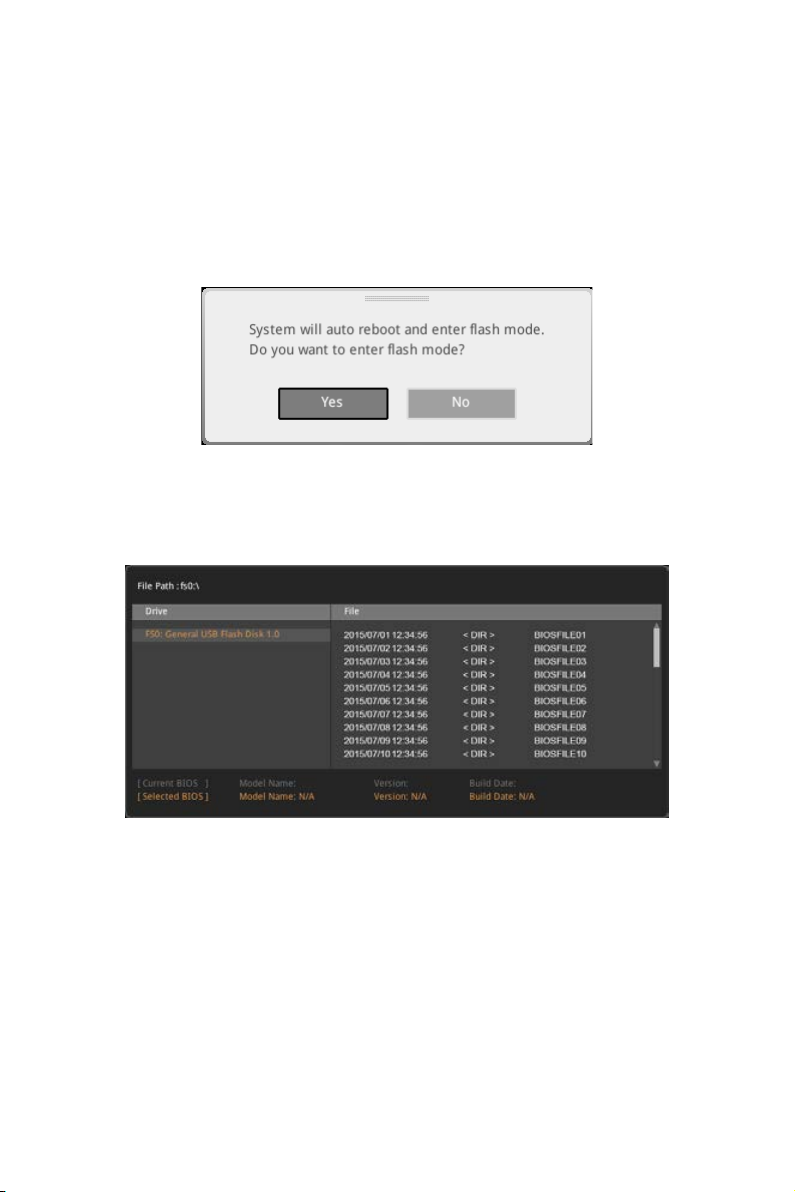
M-FLASH
M-FLASH provides the way to update BIOS with a USB flash drive. Please download
the latest BIOS file that matches your motherboard model from MSI website, save the
BIOS file into your USB flash drive. And then follow the steps below to update BIOS.
1. Insert the USB flash drive that contains the update file into the computer.
2. Click on M-FLASH tab, a demand message will be prompted. Click on Yes to
reboot and enter the flash mode.
3. The system will enter the flash mode and a file selection menu will appear after
rebooting.
4. Select a BIOS file to perform the BIOS update process.
5. After the flashing process is 100% completed, the system will reboot
automatically.
BIOS Setup
61
Page 62

OC PROFILE
f Overclocking Profile 1/ 2/ 3/ 4/ 5/ 6
Overclocking Profile 1/ 2/ 3/ 4/ 5/ 6 management. Press Enter to enter the sub-menu.
fSet Name for Overclocking Profile 1/ 2/ 3/ 4/ 5/ 6
Name the current overclocking profile.
fSave Overclocking Profile 1/ 2/ 3/ 4/ 5/ 6
Save the current overclocking profile.
fLoad Overclocking Profile 1/ 2/ 3/ 4/ 5/ 6
Load the current overclocking profile.
fClear Overclocking Profile 1/ 2/ 3/ 4/ 5/ 6
Clear the current overclocking profile.
f OC Profile Load from ROM
Load OC profile from BIOS ROM.
f OC Profile Save to USB
Save OC profile to the USB flash drive. The USB flash drive should be FAT/ FAT32
format only.
f OC Profile Load from USB
Load OC profile from the USB flash drive. The USB flash drive should be FAT/ FAT32
format only.
BIOS Setup
62
Page 63

HARDWARE MONITOR
Temperature
& Speed
Fan Manage
Setting
Buttons
Temperature/
Voltage display
f Temperature & Speed
Shows the current CPU temperature, system temperature and fans' speeds.
f Fan Manage
PWM - allows you to select the PWM mode for fan operation.
DC - allows you to select the DC mode for fan operation.
Fan step up/ down time - allows you to set the period of fan step up/ down.
Smart Fan Mode field - allows you to drag the gradient points to configure
the fan target values for Smart Fan mode. Smart Fan can control the fan speed
automatically depending on the CPU temperature to keep it with in a specific range.
If the current CPU temperature reaches to the target value, the Smart Fan function
will be activated.
Important
y
The changing will achieve after you save the changes and reboot the system.
y
Make sure fans are working properly after switching the PWM/ DC mode.
f Settings Buttons
All Full Speed - configures all fans to run at full operating speed.
All Set Default - configures all fans to run at default operating speed.
All Set Cancel - discards current changes and restores previous operating fan
speeds .
f Temperature/ Voltage display
Shows CPU/ system temperature and the current voltages of CPU, system and
memory.
BIOS Setup
63
Page 64

Software Description
Please download and update the latest utilities and drivers at www.msi.com
Installing Windows® 10
1. Power on the computer.
2. Insert the Windows
3. Press the Restart button on the computer case.
4. Press F11 key during the computer POST (Power-On Self Test) to get into Boot
Menu.
5. Select your optical drive from the Boot Menu.
6. Press any key when screen shows Press any key to boot from CD or DVD...
message.
7. Follow the instructions on the screen to install Windows
Installing Drivers
1. Start up your computer in Windows® 10.
2. Insert MSI
3. The installer will automatically appear and it will find and list all necessary
drivers.
4. Click Install button.
5. The software installation will then be in progress, after it has finished it will
prompt you to restart.
6. Click OK button to finish.
7. Restart your computer.
®
®
10 disc into your optical drive.
Driver Disc into your optical drive.
®
10.
Installing Utilities
Before you install utilities, you must complete drivers installation.
1. Insert MSI
2. The installer will automatically appear.
3. Click Utilities tab.
4. Select the utilities you want to install.
5. Click Install button.
6. The utilities installation will then be in progress, after it has finished it will prompt
you to restart.
7. Click OK button to finish.
8. Restart your computer.
Software Description
64
®
Driver Disc into your optical drive.
Page 65

APP MANAGER
APP MANAGER is a handy management application for integration of MSI applications
and software interface. Providing easy shortcut entrance and real-time update
information of all the MSI software and applications.
APP list
Total Install/ Update
Motherboard
Information
y APP list - shows all the applications and software be supported by this motherboard.
An icon represents a entrance to the application.
Colorful icon - a colorful icon means that the application had have been
installed successfully and it is available. Double click on desired icon to access
the application. A refresh icon
update version.
Gray icon - the icon with gray painting means that the application is not available
and you have to install it if necessary. Double click on the gray icon and the update
information will show. Click on the INSTALL button to install the application.
y Motherboard Information - shows the model name of motherboard.
y Total Install/ Update - click on this tab to update/ install all the applications.
shows to inform you that the application has a
Important
Please note that, once you uninstall the APP MANAGER, all the MSI applications and
software will be uninstalled simultaneously.
Software Description
65
Page 66

LIVE UPDATE 6
LIVE UPDATE 6 is an application for the MSI® system to scan and download the latest
drivers, BIOS and utilities. With LIVE UPDATE 6, you don’t need to search the drivers
on websites, and don’t need to know the models of motherboard and graphics cards.
LIVE UPDATE 6 will download the appropriate drivers automatically.
Download Options
Download List
Scan / Download / Total
Installer button
System Information
Last Scanned Date
There are Live Update, History, Setting and System Information tabs at the top. You
can click the tab to switch the control panel.
y Live Update - When you launch LIVE UPDATE 6, you will see the Live update tab at
first. This tab allows you to select files to download. You can also read the relevant
information by clicking the information icon
y History - shows the downloading history.
y Setting - allows you to specify the frequency that LIVE UPDATE 6 remind you to
update.
y System Information - displays the information of the system.
y FAQ - shows Frequently Asked Questions.
y Online Help - shows Online Help information.
on the right of the item listed.
Updating The System
This section describes how to update your system with LIVE UPDATE 6. Please follow
the steps below:
1
2
4
5
3
Software Description
66
Page 67

1. Select the Live Update tab.
2. Choose Automatic scan, system will automatically scan all the items and search
for the latest update files. Or you can choose Manual scan and select the items you
wish to scan.
3. Click the Scan button at the bottom. It may take several moments to complete the
process.
4. When the download list appears, please select the items you intend to update.
5. Click Download button at the bottom.
6. When Save Path prompt, you can specify a download directory.
7. When downloading you will see the screen below. It may take several moments to
complete the process.
8. To install the applications, simply unpack the packages and install.
Total Installer
Total Installer is a convenient feature to simplify frequent installing procedure. To use
Total Installer:
2
3
1
1. Scan updates in Live Update tab.
2. Check the Select All check-box you intend to update.
3. Click the Total Installer button. LIVE UPDATE 6 will automatically install them.
4. When prompted, click OK to complete the Total Installer procedure
5. Reboot your system.
Software Description
67
Page 68

COMMAND CENTER
COMMAND CENTER is an user-friendly software and exclusively developed by MSI,
helping users to adjust system settings and monitor status under OS. With the help
of COMMAND CENTER, making it possible to achieve easier and efficient monitoring
process and adjustments than that under BIOS. In addition, the COMMAND CENTER
can be a server for mobile remote control application.
CPU TemperatureSystem Information
Feature Menu
Feature Title
Feature
Control Panel
Previous
Feature
Option Buttons
Profile Buttons
y Default - load the default values for the current feature.
y Apply - apply your changes.
y Save - store values in the file with individual file extension.
y Load - load the values from the file.
Important
Every time you shut down the system, the configured setting will be restored to the
factory default. If you want to use the saved settings, you have to load it every time by
clicking the Load and Apply buttons.
Profile
Buttons
Next Feature
Page Indicator
Resize Corner
CPU Frequency
CPU Frequency control panel allows you to change
CPU Ratio and Base clock. You can see the current
frequency of each CPU core on the top of the panel.
Software Description
68
Page 69

CPU Fan
CPU Fan control panel provides Smart mode and
Manual Mode. You can switch the control mode by
clicking the Smart Mode and Manual Mode buttons
on the top of the CPU Fan control panel.
y Manual Mode - allows you to manually control the
CPU fan speed by percentage.
y Smart Mode - a linear fan speed control feature.
The control panel contains 4 dots allows you to
drag and adjust the Smart Speed slopes. The fan
speed will be changed along these lines with CPU
temperature. The white dot will create strip chart in
real time.
y System Fan Button - to open the system fan control
panel in new window.
y Fan Tune Button - to automatically optimize the
smart fan setting.
CPU Voltage
CPU Voltage control panel allows you to control the
CPU voltage.
Manual Mode
Smart Mode
DRAM Frequency & DRAM Voltage
y DRAM Frequency - Shows the DRAM clock, ratio
and frequency.
y DRAM Voltage - Allows you to adjust the DRAM
voltage. The risky values are displayed in red.
IGP Frequency & GT Voltage
y IGP Frequency - Allows you to adjust the IGP ratio,
and shows the IGP clock, ratio and frequency.
y GT Voltage - Allows you to adjust the GT voltage.
The risky values are displayed in red.
Software Description
69
Page 70

Option Buttons - Advanced
When click the Advanced button, The Voltage, Fan and DRAM icons will appear.
y Voltage - allows you to adjust advanced voltage values of CPU and chipset.
y
Fan - allows you to control the system fans speed.
y
DRAM - shows the current Advanced DRAM parameters, and allows you to change
the settings by selecting values from the drop-down menu on the right hand side.
Option Buttons - Setting
When click the Setting button, The Record, Warning and Mobile Control icons will
appear.
y Record - allows you to monitor the status of voltage, fan speed and temperature in
real time.
To filter record charts, select the check box next to the items.
When click the Play button, the chart pane will start to show the recording chart.
If you want to check the value of a specific spot on chart, please move the orange
vertical line to the spot.
History Record stores the data and names with date and time.
To make a history record: Select items and click the Record button. When
finished, click the Record button again. The data will be stored in the drop-down
menu.
To load a record, click the drop-down menu and select one from the list.
To delete a record, select the record that you want to delete, and click the Trash
Can icon.
Software Description
70
Page 71

y Warning - contains fields of voltage, fan speed and temperature for you to set the
threshold values. When system detects the status over your settings, a warning
message will pop-up.
y Mobile Control - is only available for the motherboard with the built-in WiFi module.
It allows you to enable/disable the COMMAND CENTER Remote Server. Please refer to
the instruction on the Mobile Control control panel.
y To start remote control: (optional)
1. Download and install MSI
®
COMMAND CENTER APP to your mobile device.
2. Enable COMMAND CENTER Remote Server on the Mobile Control panel.
3. Enable SoftAP Management.
4. Enter SSID and Password, and then click the Apply button.
5. Activate Wi-Fi
6. Run MSI
7. Find the IP address on the SoftAP Management Setting area, and enter the IP
address on your MSI
8. Press Refresh on the MSI
®
on your mobile device and connect to SoftAP with the SSID.
®
COMMAND CENTER APP on your mobile device.
®
COMMAND CENTER APP to link your system.
®
COMMAND CENTER APP to verify that monitoring and
OC functions are working properly.
Option Buttons - Information
When click the Information button, The Motherboard, CPU, Memory and HW monitor
icons will appear.
You can click the icons to open the related information.
Gadget Mode
COMMAND CENTER provides a gadget mode to
monitor the system status. You can switch between
gadget mode and full mode by clicking the arrow
icon
1. Click the Spanner icon
2. Select the check box next to the items.
3. Click the Close button.
on the top left.
y To arrange gadgets:
on the Gadget mode,
a configuration panel will slide out.
Software Description
71
Page 72

GAMING APP
GAMING APP is an application designed to quickly control your system for improving
gaming performance.
Remote Control Setting Button
Setting Button
Information Button
Cooler Boost
CPU Frequency
Control Mode Buttons
Gaming Function
Buttons
GPU Frequency
Peripheral Device
Function Buttons
y Setting Button - allows you to choose running GAMING APP when Windows starts or
let GAMING APP to overwrite the VGA fan control function.
y Information Button - shows the information of this application.
y CPU Frequency - shows the current CPU frequency.
y GPU Frequency - shows the current GPU frequency.
y Control Mode Buttons
OC Mode - apply turbo frequency to CPU and OC frequency to GPU.
Gaming Mode - automatically optimize the CPU ratio and the GPU clock.
Silent Mode - reverts the CPU ratio and GPU clock to the default values.
y Gaming Function Buttons - allows you to use OSD and Eye Rest functions.
y Peripheral Device Function Buttons - allows you to set the Gaming Hotkey, Mouse
Master, VR Ready and Voice Boost functions.
y Remote Control Setting Button - available for the motherboards with built-in or
discrete WiFi module. It allows you to set up Name and Password to link the android
device and the motherboard. Please follow the steps below to complete the remote
control setting.
1. Download and install the MSI
®
GAMING APP APP to your android device.
2. Set up a set of Name and Password on the Remote Control Setting panel, and
then click the Apply button.
3. Connect your android device and motherboard to the same local area network.
4. Run MSI
5. Press the Remote Control Setting icon on the MSI
®
GAMING APP APP on your android device.
®
GAMING APP APP to find the
paired device Name you set in the Remote Control Setting panel.
6. Enter the Password you set in the Remote Control Setting panel.
7. Finally, you can use the MSI
®
GAMING APP APP to control your motherboard with
the android device.
Software Description
72
Page 73

Eye Rest
Eye Rest allows you to optimize the display on your monitor.
y EyeRest - reduces blue-light of your LED backlit screen, in order to protect your
eyes.
y Gaming - automatically increase contrast ratio of your screen.
y Movie - automatically increase dynamic contrast ratio of your screen.
y Customize - allows you to adjust gamma, contrast and color balance for your screen.
y Default - loads the default settings.
Software Description
73
Page 74

Gaming Hotkey
Gaming Hotkey provides instant control of the system through user defined hotkeys.
Categories Toggle
Hotkey Manager
Current Hotkeys
Gaming Hotkey ON/OFF
y Gaming Hotkey ON/OFF - allows you to turn ON/OFF the Gaming Hotkey function.
y Categories Toggle - allows you to toggle over the Hotkey categories.
Macro Genie - provides the keyboard and mouse macro record function and
allows you to define the hotkeys for the macro recorder.
1. Click on the Record button to start the keyboard and mouse macro recorder.
2. Click on the Stop button to stop the recorder.
3. Key-in a file name and set-up the parameter for the macro.
4. Finally, click on the Save button to save the recorded macro.
Windows Keys - allows you to define hotkeys to replace Windows default
keyboard shortcuts.
Login Keys - provides hotkey login function.
MSI Smart Keys - allows you to define hotkeys for MSI Smart Keys.
y Hotkey Manager - allows you to create, edit and delete hotkeys.
y Current Hotkeys - shows all existing hotkeys.
Important
y
The Caps Lock, Num Lock, Scroll Lock, Window Home, Application and BackSpace
keys can not be used as Hotkeys.
y
Some key combinations are reserved for use by Microsoft Windows and can not be
assigned as a hotkey.
Software Description
74
Page 75

Mouse Master
Mouse Master provides mouse macro function. You can also use it to change DPI of
your mouse.
Delay Time
Macro Hot Key
Mouse Action
Action List
Edit Buttons
Load Button
Save Button
DPI Setting
Default Button
DPI Hot Key
Test Area
Clear Button
y Delay Time - allows you to apply a delay time in mouse macro.
y Macro Hot Key - allows you to assign a hotkey from A to Z to activate the macro.
y Mouse Action - assigns mouse actions to the macro.
New - captures the mouse coordinate and add to the macro.
Left - add a left-click to the macro.
Middle - add a middle-click to the macro.
Left - add a left-click to the macro.
y Action List - shows the actions of the current macro.
y Edit Buttons - there 3 buttons for editing the macro.
Run - activates the macro.
Delete - removes the selected action from the macro.
Clear - removes all actions from the macro.
y Load Button - allows you to load a macro.
y Save Button - allows you to save the macro to a file.
y DPI Setting - allows you select the mouse DPI from the drop-down menu.
y Default Button - reverts to the default DPI setting.
y DPI Hot Key - allows you to assign a hotkey from A to Z to activate the DPI setting.
Please note that you muse hold the hotkey to keep the DPI setting. When you release
the hotkey, the DPI setting will be reverted to default.
y Test Area - allows you to test the mouse movement.
y Clear Button - clears the test area.
Software Description
75
Page 76

VR Ready
It will optimize the performance of your system to ensure everything is VR Ready.
VR ON/ OFF
Applications
y VR ON/ OFF -enables or disables VR settings.
y Applications - appears when you turn on the VR support. It allows you to close some
applications to optimize the system for better VR experience.
Voice Boost
Voice Boost function allows you to boost volume in voice communication tools.
ON/ OFF toggle
VoIP Selection
VoIP Setting
y ON/ OFF toggle -enables or disables Voice Boost function.
y VOIP Selection - selects your voice communication tool.
y VOIP Setting - adjust the volume ratio in voice communication tool.
Important
The Voice Boost function is only available with Nahimic 2.5/ 3 and voice communication
tools (TeamSpeak, Raidcall, Skype, SkypeHost and Discord).
Software Description
76
Page 77

X-BOOST
The MSI X-BOOST allows you to select the system performance mode to meet your
current system environment or support faster storage access speed for your external
storage or memory cards.
Easy
In Easy page, you can select one system performance mode to meet the current
system environment.
Setting
Performance
mode
Performance
information
y Performance mode - moves over the mouse to any one of performance mode and
click on the ON button to enable it.
Important
The Customize mode is the default of system performance.
y Performance information - displays the system performance diagram of enabled
mode.
y Setting - enables or disables Run X-BOOST when windows starts.
Software Description
77
Page 78

Advance
In Advance page, you can enable the USB SPEED UP, the STORAGE BOOST and VR
BOOST.
Setting
Device
information
y Device information - displays the information and current transfer rates/ access
speeds of USB/ storage devices.
y Setting - enables or disables Run X-BOOST when windows starts.
y USB SPEED UP - supports faster data transfer rates of the USB storage devices.
y STORAGE BOOST - supports faster access speed of storage device.
Important
y
Please note that you can only select one mode at a time from Easy or Advance page
as MSI X-BOOST function.
y
The improved transfer rate/ access speed will vary with the USB/ storage device.
Software Description
78
Page 79

MYSTIC LIGHT
MYSTIC LIGHT is an application allows you to control LED lights of MSI products.
For some earlier products, you can go to product download page to download the
applicable LED control software.
Main Screen
The Main screen is used to configure what devices need to be synchronized and LED
light effect options.
ON/ OFF All LED
SYNC PROFILE
Right hand
side panel
Apply Button
Save Button
Live Preview
y ON/OFF All LED - By toggling Off/On here, you
disable/enable all the LED on supported gaming gear,
memory, graphics card and motherboard etc.
y SYNC PROFILE - In this section, you may apply different LED setting to your device.
All Sync - Default: All the Sync device bubble would appear red.
To change the LED color & effect, use the panel on the right hand side to switch to
different settings.
Please noted that for light effect, the option would be
more or less depending on the devices you have, it will
only list the light effects which are available for all
included devices.
For the color section, you can always select a different
color but it won’t apply to the device that does not have
such color.
Software Description
79
Page 80

You can also change settings for single device. To do that, you have to click the
sync bubble twice and make it turn gray as below.
Then you go to DEVICE SETTING and click SETTING.
click SETTING
After that, the computer will open a different windows and you can modify LED
there individually.
Note: The
motherboard
picture and
name may
vary according
to different
models.
Individual - Default: All the Sync device bubble would appear black.
To change color for individual device, use the device setting panel below to lock on
any device and click SETTING to customize the LED color/effect on it.
Software Description
80
You can save the current settings by clicking Save.
click SETTING
Page 81

If you wish to customize multiple device at the same time, click the bubble until it
turn red like below.
Use the LIGHT EFFECT & COLOR section on the main menu to make change.
Note:
Currently only GTX 1080 Ti Lightning -/X/Z and GTX 1080
Ti Gaming -/X Trio supports Light Speed/Brightness and
no device supports Direction.
Profile01~03 - Save Sync profile settings.
y Save Button - saves sync device settings and lighting effect settings to the current
Sync Profile.
Software Description
81
Page 82

Motherboard Screen
The motherboard screen is used to configure the LED light effect of the motherboard.
SYNC ALL
Return Button
ON/ OFF ALL LED
PROFILE
LED AREA
Apply Button
Save Button
Motherboard
Name
Live Preview
Light Effect
Options
Note: The motherboard picture and name may vary according to different models.
y Return Button - returns to the main screen.
y ON/OFF ALL LED - allows you to turn ON/ OFF all LED lights of the motherboard.
y SYNC ALL - allows you to synchronize all LED light effect of the motherboard.
y Motherboard Name - shows the name of the motherboard.
y Live Preview - gives you the full experience of your configuration’s look, feel while
you are editing it.
y Light Effect Options - allow you to customize lighting effect of the sync devices.
LIGHT EFFECT - allows you to change LED light effect.
LIGHT SPEED - allows you to change LED light speed.
BRIGHTNESS - allows you to change LED light brightness.
Note:
Currently only Z370 GODLIKE GAMING, H370 GAMING PRO CARBON and B360
GAMING PRO CARBON support Light Speed/Brightness.
COLOR - allows you to select the color for single light effects (Stack, Breathing,
Flashing etc.).
y Apply Button - applies lighting effect settings.
y PROFILE - manages sets of motherboard LED light effect settings.
y Save Button - saves sync device settings and lighting effect settings to the current
profile.
y LED AREA - switches to the other LED area on the motherboard.
Software Description
82
Page 83

MYSTIC LIGHT PARTY
This section allows you to control LED across different platform. The pre-requisite is
that the platforms should all be connected within the same local network. Refer to
device support list web page. https://www.msi.com/Landing/Mystic-Light-Party.
PARTY
Upon clicking PARTY, this window would pop out. On your master platform, click + to
create a host group.
Click + to create a host group
Enter the group name (3~15 characters) and group array (13~30 columns, 5~30 rows)
and click the CREATE button.
Software Description
83
Page 84

The group has been created. The other computers in the same local network are able
to join the group with MYSTIC LIGHT software.
DELETE Group Button
Control Group Button
Invitation Status Indicator
Group In/Out Status
DELETE Group Button - deletes the group.
Control Group Button - enters the group control panel.
Invitation Status Indicator - appears when receive an invitation to a group.
Group In/Out Status - shows Group In/Out status.
Joining Group
On your slave platform, click PARTY to open MYSTIC LIGHT PARTY interface and click
In to join the network.
Software Description
84
JOIN Button
Page 85

Group Control Panel
If everything is set up properly, you can see your slave platform on master platform
MYSTIC LIGHT PARTY window.
APPLY button
Group Members Icon
Light Effect Options
Invite Button
Color Selection
At the panel below, you may apply different LED settings and color to the selected
platform.
Please be aware of certain limitation on the devices such as if you apply green color
to a red-only device, the LED will stay off since it has on such color or if you apply
rainbow to a no-rainbow mode device, the LED will stay on constantly.
y Group Member Icons - displays members status, and you can select a member to
delete it in the DELETE pop-up window.
Light Color
Member Serial Number
Selected Indicator (The red border)
Wi-Fi Indicator (Indicates that the device is connected over Wi-Fi)
DELETE the member
Software Description
85
Page 86

y Invite Button - enters the INVITE screen.
y Light Effect Options - allow you to customize lighting effect.
Off
Flash
Marquee
y Color Selection - allows you to change color.
Always on
Double flash
Rainbow Sound beat
Breathe
Random
Inviting Member
Click the Invite button in the Group Control Panel to enter the INVITE screen. Select
the device you want to invite and click the INVITE button.
INVITE Button
Software Description
86
Page 87

SMART TOOL
SMART TOOL is a convenient tool that can help you to create your Windows installation
USB flash drive, and it can also create a super RAID.
Main menu
After installing and activating SMART TOOL, it will display a main menu for you to
choose Smart Tool or SUPER RAID. Note that the SUPER RAID is only available when
your system equipped with at least 3 hard-disk drives (1 system disk and 2 data disks).
SMART TOOL
Before you can create your Windows installation USB flash drive, you’ll need to have
your Windows Installation DVD or ISO file, and also have a minimum of a 8GB USB
flash drive to create your installer. Be sure to backup files on the USB drive, this
process will erase it.
To create the Windows installation USB drive:
Step1. Choose source folder
y In the Source folder box, click Browse button and select the file from the dialog box.
(This option will copy all Windows installation files.)
y Add USB drivers to USB pan driver option allows you to add USB driver on the USB
pen drive. This option appears depend on the motherboard you purchased.
Step2. Choose Storage device
y Choose USB storage and select your USB flash drive in the drop-down list. In case
the USB flash drive is not listed, click the Refresh Drive button.
y If you want to install Windows on the RAID drive, select the RAID driver version from
the drop-down menu.
y If you want to add NVMe drive for your NVMe SSD drive, check the Add NVMe driver
checkbox.
Important
You can also create an installer ISO image file by selecting the ISO destination in
Step2, and then burn it onto the DVD. However, this method does not support RAID
driver.
Step3. Click the Start buton.
Software Description
87
Page 88

SUPER RAID
This utility allows you to create a super RAID in Windows system.
To create a super RAID:
1. Use checkboxs to select the disks you want included in your RAID.
2. Choose Speed Up or Backup for RAID type.
y Speed Up = RAID0
y Backup = RAID1
3. Click Start.
4. When prompt Finish!, click OK.
Important
SUPER RAID can't includ the system disk.
Software Description
88
Page 89

RAMDISK
RAMDISK creates a virtual RAM drive using the available memory in your computer,
the performance of the RAMDISK is faster than an SSD and hard drive. RAMDISK
allows you to store any temporary information on it. Furthermore, using the RAMDISK
will extend your SSD’s life by sparing it from excessive reading and writing.
Creating a RAM Disk
When RAMDISK is started, it will create a default RAM disk. If you want to change
settings, refer to following instructions.
Setting
Backup
Management
Option
Apply
Button
y Setting - specify Letter, Name, Size and Format of the RAM disk.
y Option - select browser temporary files to save/load on the RAM disk. You can also
add software files to improve reading speed.
y Backup - specify backup and restore settings to prevent data loss. All files will be lost
each time the RAMDISK is stopped if you do not backup.
Browse Button - set the path to the image file.
Backup Right Now Button - manually backup files.
Restore On Boot - check this box to have the image file loaded automatically when
RAMDISK starts.
Auto Backup - check this box to backup automatically over a period of time.
y Apply Button - allows you to apply changes.
y Management - shows RAMDISK information and allows you to delete files.
Remove the RAM disk
Dislpay
information
Delete files
in the RAM
disk.
Software Description
89
Page 90

GAMING LAN MANAGER
GAMING LAN MANAGER is an utility for traffic shaping for the Windows 10. It can keep
your internet fast during heavy upload/ download and improve your ping for online
games. If your motherboard has a Wi-Fi module, GAMING LAN MANAGER provides
virtual access point function for traffic shaping for your mobile devices.
y Applications - displays currently using network bandwidth applications. You can
prioritize Games, Medias or File sharing programs as high as possible.
y Performance - shows top 5 applications by total traffic, allows you to monitor
network bandwidth usage.
y Network Test - allows you to setup bandwidth control.
y Advanced Setting - allows you to expand RWIN to accelerate download speed. You
can also block IP address and setup virtual access point.
y Information - shows version information.
y WiFi Analysis - shows wireless signal strength and information.
Software Description
90
Page 91

Configuring Bandwidth
This section describes how to configure Internet Provider Speed. You can configure
default internet upload and download bandwidth from the Network Test tab on the
GAMING LAN MANAGER window.
Important
Before using the GAMING LAN MANAGER for the first time, you should use the
Test Network Speed button which runs a speed test of your current total Internet
bandwidth delivered through your Internet service provider.
To test the Upload and Download speed and configure bandwidth, please follow the
steps below:
1
3
4
2
1. Click the Network Test block in GAMING LAN MANAGER.
2. Click Test Network Speed button. The test takes several minutes to test your
network speed.
3. Enter the testing results into Upload Speed and Download Speed fields.
4. Check the Enable Bandwidth Control to allow the GAMING LAN MANAGER to
manage the bandwidth.
Software Description
91
Page 92

Nahimic 3
Nahimic 3 is designed to offer the best audio experience it contains audio effects,
microphone effects and Sound Tracker.
Installation and Update
Nahimic 3 is included in the audio driver. If you need to install it or update it, please
use the Driver Disc with your motherboard or download the driver from MSI’s official
website.
Audio Tab
From this tab, you can access all of Nahimic 3’s audio effects, audio profiles and
settings.
Device display & Volume
y Device display & Volume - displays the type of audio device currently being used as
output, as well as its current volume.
Mute - mutes the current audio output device.
y Audio profiles - allows you to choose between 4 factory audio profiles to fit your
multimedia experience (Music, Gaming, Movie or Communication). All profiles can be
modified as you wish.
y On/Off Button - allows you to turn all of Nahimic 3’s audio effects in one click.
y Audio Effects - allows you to separately control any of the 5 audio effects.
Surround Sound - it is an audio effect mainly dedicated to headphones acoustic
experience.
Gaming and Movies - virtualizes the multichannel audio stream from the
game engine or the movie soundtrack and downmixes it in order to retrieve a
multichannel listening experience over your stereo headphones or speakers.
Music - expands the stereo for a wider sound stage.
Volume Stabilizer - it maintains a constant volume for all elements of the audio
experience (dialogs, soundtrack, explosions, etc.) to make them all sound softer,
balanced or louder. The Quiet On / Off option allows to enter a night mode by
removing some basses. This way, you won’t disturb people around you if you’re
using speakers to play your media.
On/Off Button
Audio Profiles
Reset Button
Try Button
Audio Effects
Software Description
92
Page 93
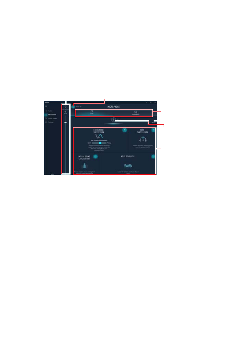
Voices - it boosts (or removes) the speech in movies, video games and incoming
communication from -12 to +12 dB.
Bass - increases (or decreases) the energy in low frequencies from -12 to +12 dB.
Treble - increases (or decreases) the energy in high frequencies from -12 to +12
dB.
y Reset Button - restores the current profile to its default values.
y Try Button - launches an audio sample that allows to test audio settings.
Microphone Tab
From this tab, you can access all of Nahimic 3’s microphone effects and settings.
Device display & Volume
y Device display and volume - displays the type of recording device currently being
used as input, as well as its current volume..
Mute - mutes the current mic device.
y Mic profiles - allows you to choose between 2 factory mic profiles to fit your
experience (Chat or Conference). All profiles can be modified as you wish.
y On / Off button - allows you to turn on and off all Nahimic 3’s microphone effects in
one click.
y Microphone Effects - allows you to separately control any of the 4 microphone
effects.
Static Noise Suppression - it removes the static noises like the ones coming from
your computer fans.
Echo Cancellation - improves the voice quality by cancelling the echo.
Lateral Sound Cancellation - it only records the sound coming from the front of
your microphone.
Voice Stabilizer - Levels the volume of your voice in order to avoid any saturation
and maintains a constant and clear communication.
y Reset Button - restores the current profile to its default values.
y Try Button - Turns the microphone loopback On/Off.
On/Off Button
Microphone
Profiles
Reset Button
Try Button
Microphone
Effects
Software Description
93
Page 94

Sound Tracker Tab
The Sound Tracker is an FPS oriented feature that provides a visual indication
localizing the sources of the sounds while in a game. These are represented by
dynamic segments pointing the direction of the sounds: the more opaque they are,
the stronger the sounds are. Thanks to this feature, players are able to pick up an
approaching threat more definitively and easily, thereby being even more dynamic.
The Sound Tracker captures the 5.1 and 7.1 sound streams processed by your audio
system, and is displayed in the applications and games using DirectX 9, 9c, 10 and 11.
Try ButtonOn/Off Button
Compatible
games
Sound Tracker
Sound Tracker
Effects
y ON / OFF Button - allows you to enable/ disable the Sound Tracker by switching this
option ON/ OFF.
y Try Button - launch a 7.1 audio sample allowing you to preview how the radar will
react in your game.
y Sound Tracker Effects
Size - allows you to adjust the scale of the Sound Tracker, making it look bigger or
smaller.
Transparency - allows you to adjust the transparency of the Sound Tracker,
making it look more or less discrete.
Color - click the colored circle to open the color edition window. You can apply the
color you want to the dynamic segments.
y Compatible games - clicking this link opens the official Nahimic website, and leads
to the list of compatible games able to display the Sound Tracker.
Settings Tab
In this section, it allows you to select the language of Nahimic 3’s UI.
Software Description
94
Page 95

RAID Configuration
Below are the different types of a RAID.
RAID 0 breaks the data into blocks which are written to separate hard drives.
RAID 1 provides data redundancy by mirroring data between the hard drives and
RAID 10 uses four hard drives to create a combination of RAID 0 and 1 by forming a
RAID level comparison
All the information/ volumes/ pictures listed in your system might differ from the
illustrations in this appendix.
Using AMD RAID Controller BIOS Configuration Utility
Enter BIOS and change the SATA Mode setting to RAID Mode, press F10 to save the
changing, and then reboot. When booting the system, press Ctrl+R when the BIOS
banner displays. After entering AMD RAID Controller BIOS Configuration Utility, the
following screen is displayed.
Spreading the hard drive I/O load across independent channels greatly
improves I/O performance.
provides enhanced read performance.
RAID 0 array from two RAID 1 arrays.
RAID 0 RAID 1 RAID 10
Minimum # drives 2 2 4
Data protection None Excellent Excellent
Read performance Excellent OK OK
Write performance Excellent Good Good
Capacity utilization 100% 50% 50%
Important
Creates an array from the connected disks
1----RAID5, 999GB, Ready(R/W)
AMD-RAID Array Configuration
Arrays Disks
0-00,500GB,Online
0-01,500GB,Online
0-02,500GB,Online
0-03,500GB,Online
Initialize Disk(s)
Create Array
Delete Array(s)
Swap Two Arrays
Manage Hot Spare(s)
View Disk Details
View Array Details
Rescan All Channels
Controller Options
Continue to Boot
Main Menu
<↑><↓><→><←>=Choose, <Esc>=Back
Enter=Select Menu Item
Available Keys
RAID Configuration
95
Page 96

Using the utility to accomplish the procedures
y Initialize Disk(s) - To initialize a new disk drive for data storage.
y Create Array - Create arrays at different RAID levels (depending on the license level
for the system)
y Delete Array(s) - Delete an array.
y Swap Two Arrays - Change the array order, especially for the AMD-RAID bootable
array.
y Manage Hot Spare(s) - Allows selection of global and dedicated hot spares.
y View Disk Details - View information about each disk.
y View Array Details - View information about each array.
y Rescan All Channels - Rescan all channels to detect new or removed disks and
arrays.
y Controller Options - Change INT13 boot support, turn off Critical arrays or warning
for Offline arrays while booting, or change the number of disks that can be spun-up
when the system is powered-on.
y Continue to Boot - Exit the BIOS Configuration Utility and continue booting the
system.
Understanding the Colour Code
Colour codes indicate the type or status of information at the BIOS Configuration
Utility.
y White text - Indicates an available option or informational text.
y Black text, yellow highlighting - Indicates an option or device for which action might
be taken.
y Yellow text - Indicates information about the yellow-highlighted option.
y Green text - Indicates an item that has been selected.
y Light blue text - Indicates that the item cannot be selected.
y Magenta text - Indicates items that are related to spares or boot options.
y Red text - Indicates a failed virtual or physical disk or a warning. For example,
informational text might be red if an option is not available.
RAID Configuration
96
Page 97

Initialize Disks
New disks and legacy disks must be initialized before they can be used to create an
AMD-RAID array. Initialization writes AMD-RAID configuration information (metadata)
to a disk.
Important
y
If a disk is part of an AMD-RAID array, the disk cannot be selected for initialization.
To initialize the disk anyway, delete the AMD-RAID array. Data on the disk is deleted
during initialization so ensure the correct disks are chosen to initialize.
y
A legacy disk can contain valid data. When a legacy disk is initialized, all data on the
disk is lost.
To initialize disks
1. At the Main Menu, use the arrow keys to highlight Initialize Disk(s).
Initializes one or more disks so that arrays can be created
AMD-RAID Array Configuration
Arrays Disks
0-00,640GB,Ready
0-01,640GB,Ready
Initialize Disk(s)
Create Array
Delete Array(s)
Swap Two Arrays
Manage Hot Spare(s)
View Disk Details
View Array Details
Rescan All Channels
Controller Options
Continue to Boot
Main Menu
<↑><↓><→><←>=Choose, <Esc>=Back
Enter=Select Menu Item
2. Press Enter to select Initialize Disk(s).
3. Select the disks to initialize by pressing Insert key.
4. Press Enter to initialize the selected disks.
5. Press the C key to confirm the initialization.
Available Keys
RAID Configuration
97
Page 98

Create Arrays
Arrays can be created after the disks are initialized.
Important
y
For redundant arrays, the Create process is not finished until after the operating
system and AMD-RAID OS drivers have been installed and the system has booted to
the operating system. However, the arrays are immediately available to use for either a
bootable array or a data array.
y
If the system is booted from an AMD-RAID bootable array, the first array in the
Arrays section must be the bootable array. The system boots only from the first array
in the Arrays section. As necessary, use the Swap Two Arrays feature to swap arrays
and place the bootable array in the first position.
To create an array
1. At the Main Menu, use the arrow keys to highlight Create Array and press Enter.
2. Select the disks with which to create the array by pressing Insert key.
RAID0: Stripe set - distributes space across disks for higher performance
AMD-RAID Array Configuration
Arrays Disks
0-00,640GB,Ready
0-01,640GB,Ready
Disk: 0,2
Type: RAID0
Select Array Type to Create
RAID5 RAID10N
RAID0 RAID1N
RAID1 Volume
RAID10 RAIDABLE
RAID50
Create Array
User Input
<↑><↓><→><←>=Choose, <Esc>=Back
Enter=Select Menu Item
Available Keys
3. Press Enter to include the selected disks in the array.
4. In the User Input section, use the arrow keys to select an array type. Only array
types that can be created with the selected disks are available.
5. Press Enter.
6. Select an array size.
7. Press Enter when either the desired size or the maximum available size is
reached.
8. Select a caching level using the arrow keys and press Enter.
9. Press C to confirm the array settings.
RAID Configuration
98
Page 99

Delete Arrays
Important
Deleting an array permanently destroys all data that is on the array. This action cannot
be undone and it is very unlikely the data can be recovered.
To delete an array
1. At the Main Menu, use the arrow keys to highlight Delete Array and press Enter.
Deletes one or more arrays that are configured on this controller
1----RAID0, 1.2TB, Normal(R/W)
AMD-RAID Array Configuration
Arrays Disks
0-00,640GB,Online
0-01,640GB,Online
Initialize Disk(s)
Create Array
Delete Array(s)
Swap Two Arrays
Manage Hot Spare(s)
View Disk Details
View Array Details
Rescan All Channels
Controller Options
Continue to Boot
Main Menu
<↑><↓><→><←>=Choose, <Esc>=Back
Enter=Select Menu Item
2. Select the arrays to delete by pressing Insert key.
3. Press Enter to delete the selected arrays.
4. Press C to confirm the deletion.
Available Keys
RAID Configuration
99
Page 100

Swap Arrays
Use the Swap Two Arrays option to arrange arrays in a different order.
Important
If more than one array is created, install the operating system to any of them.
However, a small amount of boot information is always written to a disk(s) in the first
array (Array 1) of the Array section, regardless on which array the operating system is
installed.
If anything happens to a disk in Array 1, the system might not be able to boot. It is
recommended that the user install the operating system on an AMD-RAID bootable
array at a redundant RAID level such as RAID1 or RAID5 and swap the array into the
first position, if it is not already Array 1.
To swap arrays
1. At the Main Menu, use the arrow keys to highlight Swap Two Array and press
Enter.
Swaps arrays to allow them to load in any order (Boot array is first)
1----RAID0, 1.2TB, Ready(R/W)
2----RAID0, 1.2TB, Ready(R/W)
AMD-RAID Array Configuration
Arrays Disks
0-00,640GB,Online
0-01,640GB,Online
0-02,640GB,Online
0-03,640GB,Online
Initialize Disk(s)
Create Array
Delete Array(s)
Swap Two Arrays
Manage Hot Spare(s)
View Disk Details
View Array Details
Rescan All Channels
Controller Options
Continue to Boot
Main Menu
<↑><↓><→><←>=Choose, <Esc>=Back
Enter=Select Menu Item
2. Select the arrays to swap by pressing Insert key.
3. Press Enter to swap the arrays.
Available Keys
RAID Configuration
100
 Loading...