

Page 1

1
V1.2 Motorola Mobility Inc. Confidential Proprietary 10/02/2013
Moto X
Field Service
Trouble Shooting Guide
Page 2
2
V1.2 Motorola Mobility Inc. Confidential Proprietary 10/02/2013
Table of Contents
Section
Title
1.0
1.0 Revision History
2.0
2.0 EE Hardware Profile Overview
3.0
3.0 Snapshots of Antennas
4.0
4.0 Schematic and Component Overlays
5.0
5.0 RF Troubleshooting
5.1.1
5.1.1 CDMA RF Troubleshooting
5.1.2
5.1.2 WCDMA/GSM RF Troubleshooting
5.1.3
5.1.3 LTE RF Troubleshooting
5.2
5.2 GPS Subsystem Troubleshooting
5.3
5.3 BT/WiFi Subsystem Troubleshooting
5.4
5.4 NFC Troubleshooting
6.0
6.0 No Turn On Troubleshooting
7.0
7.0 Display Subsystem Troubleshooting
8.0
8.0 Touch Subsystem Troubleshooting
9.0
9.0 Camera Flash Driver Troubleshooting
10.0
10.0 Audio Subsystem Troubleshooting
11.0
11.0 Miscellaneous Baseband Troubleshooting
Page 3
3
V1.2 Motorola Mobility Inc. Confidential Proprietary 10/02/2013
1.0 Revision History
Ver
Date
Author
Notes
1.0
07/23/2013
Suresh Sethuraman
Initial document created.
1.1
08/20/2013
Manjeet Bhalla
Updated missing blocks
1.2
10/02/2013
Manjeet Bhalla
Updated Table of Contents and filled in missing
sections.
Page 4

4
V1.2 Motorola Mobility Inc. Confidential Proprietary 10/02/2013
2.0 EE Hardware Profile Overview
Moto X (XT1058)
Bands/modes
GSM 850/900/1800/1900, GPRS,
WCDMA850/900/1900/2100, HSPA+(CAT14)
CDMA 850/1900 + Diversity
LTE band 13 + Diversity
RF
RTR8600(GSM/UMTS/LTE RX/TX function integrated)
RTR8605(CDMA RX/TX function integrated)
MMPA including WCDMA 850/2100 and Quad-band GSM PA Module
WCDMA900 PA Module
WCDMA1900 PA Module
CDMA850 PA Module
CDMA1900 PA Module
LTE B13 PA module
Baseband Chipsets
MSM8960Pro (Baseband processor)
PM8921 (power management)
WCN9310 (Audio Codec)
Application Chipsets
MSM8960 (dual core 2, 1.5GHz application processor)
Memory (eMMC)
8GB eMMC
Memory (RAM)
2GB LPDDR2 SDRAM
Display
4.3” qHD 540*960 AMOLED
Camera
8 MP w/ flash (rear), VGA (front)
Bluetooth/WiFi
WCN3680
Connectivity
Micro USB
Other
3.5mm headset jack
Page 5

5
V1.2 Motorola Mobility Inc. Confidential Proprietary 10/02/2013
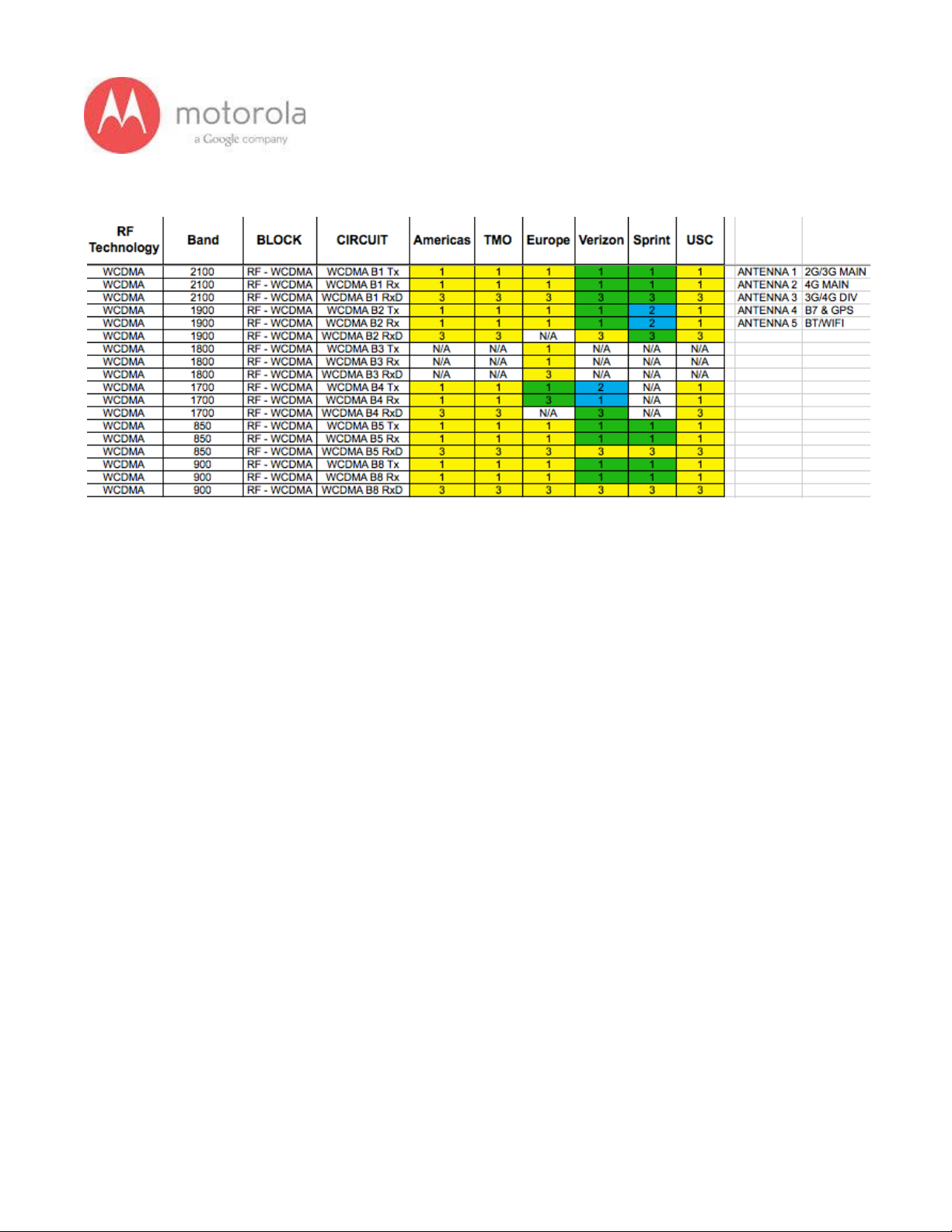
EE Hardware Profile Overview
○ RF Band Support
Page 6
6
V1.2 Motorola Mobility Inc. Confidential Proprietary 10/02/2013
Page 7

7
V1.2 Motorola Mobility Inc. Confidential Proprietary 10/02/2013
3.0 Snapshots of Antennas
1. ATT/Vow/Sprint/USC/TMO/Europe:
Page 8
8
V1.2 Motorola Mobility Inc. Confidential Proprietary 10/02/2013
4.0 Schematic and Component Overlays
● Main PCB Overlays and schematics - see service
portal for files
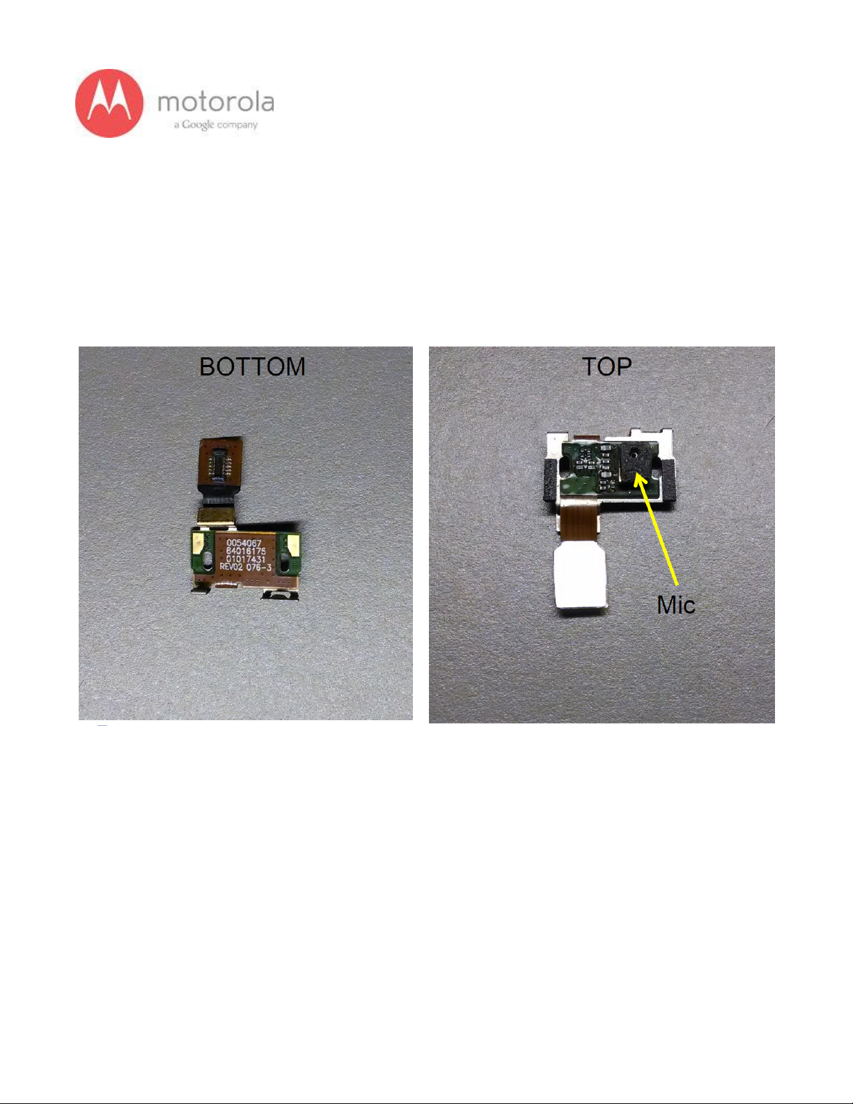
● Snapshots of Flex Assemblies
Audio Flex
Page 9
9
V1.2 Motorola Mobility Inc. Confidential Proprietary 10/02/2013
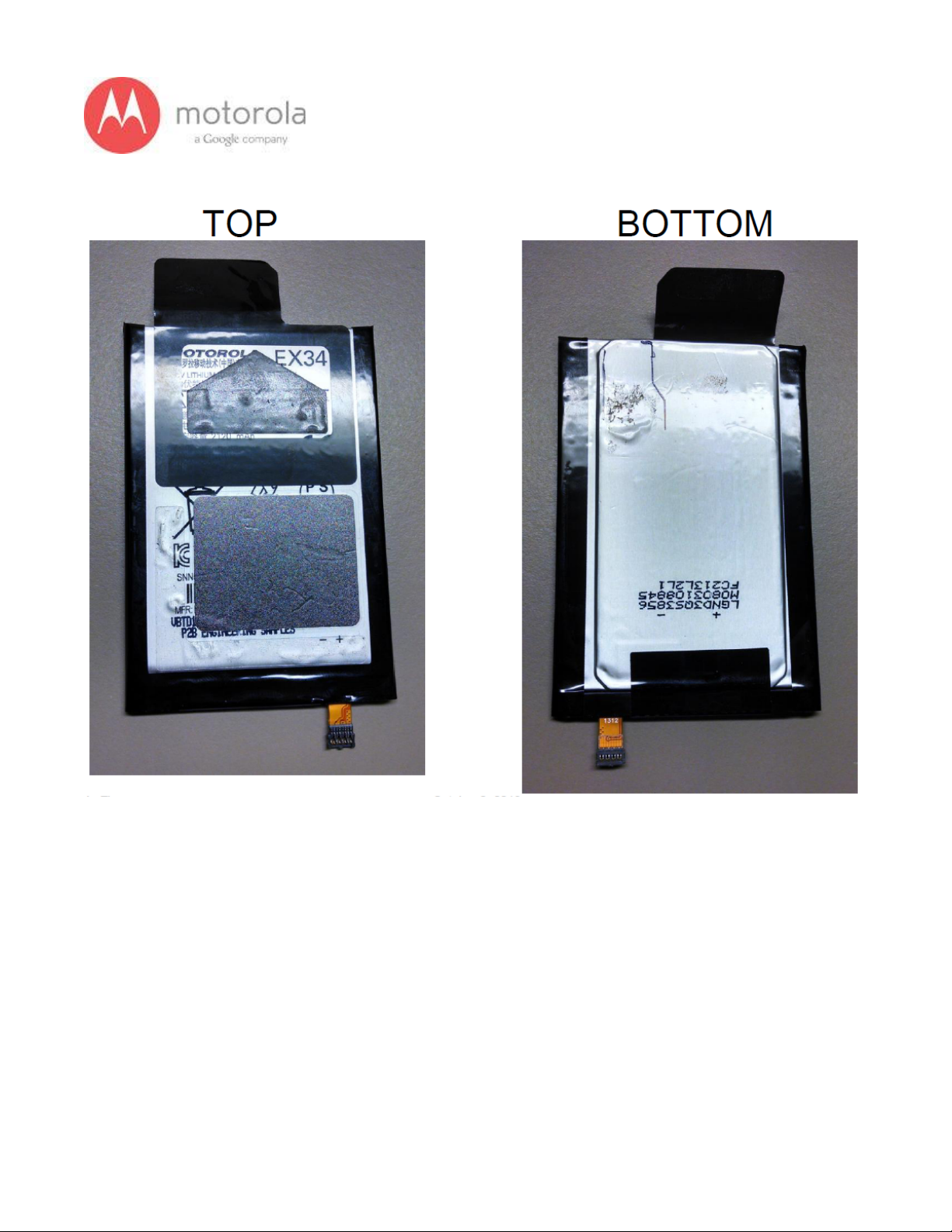
Battery/Battery Flex
Page 10
10
V1.2 Motorola Mobility Inc. Confidential Proprietary 10/02/2013
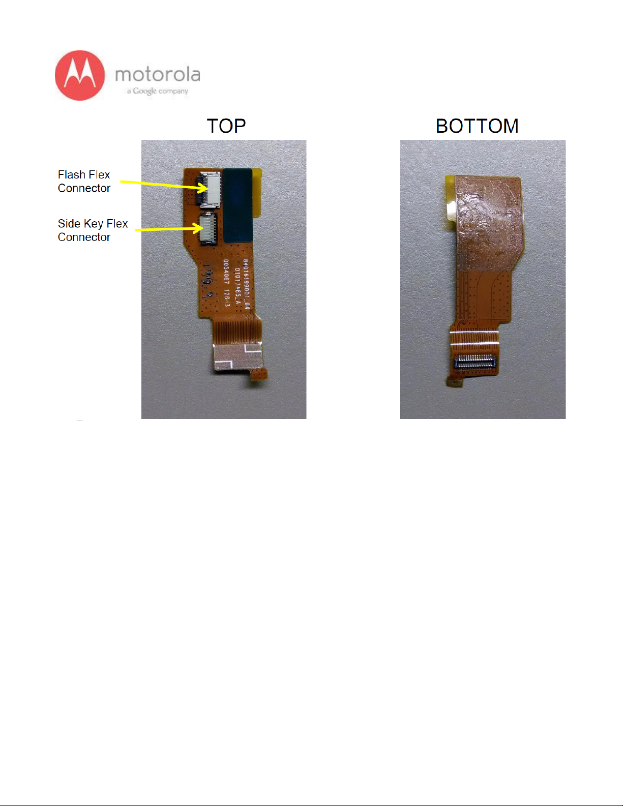
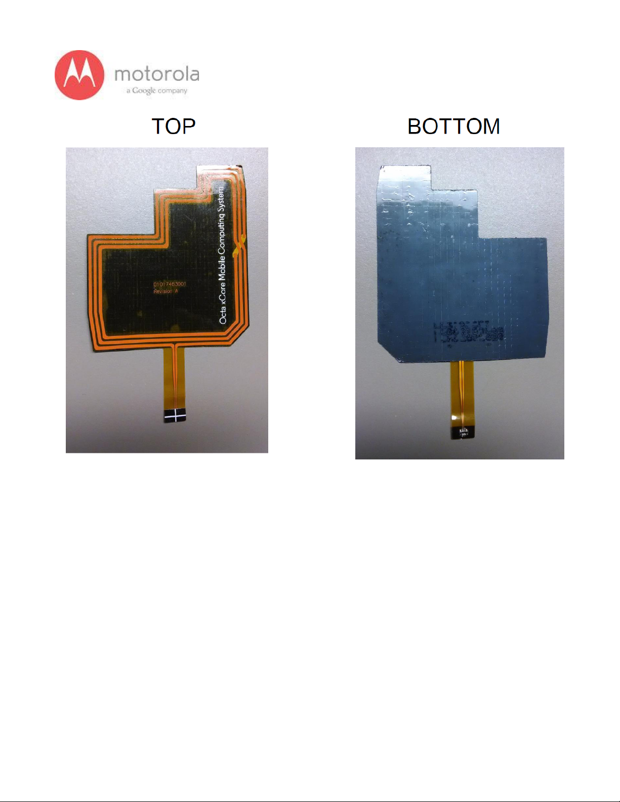
Bridge Flex
Page 11
11
V1.2 Motorola Mobility Inc. Confidential Proprietary 10/02/2013
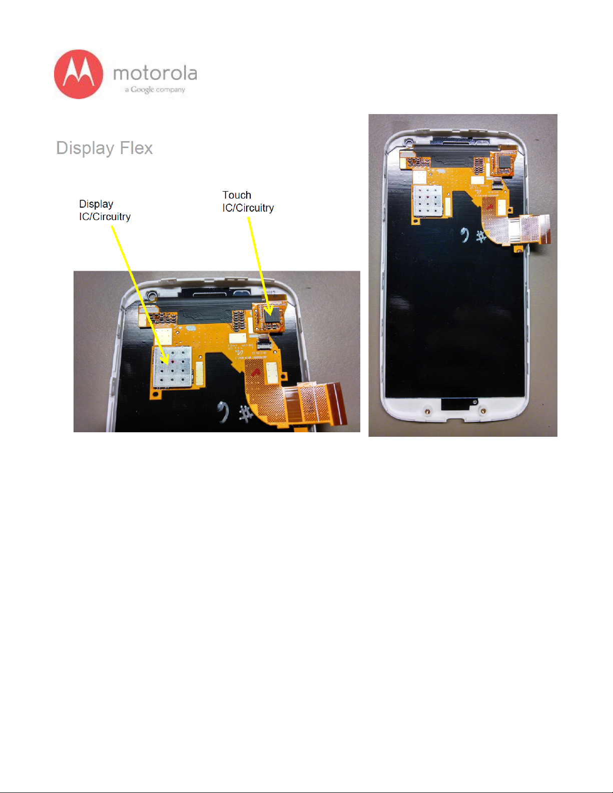
Display Flex
Page 12
12
V1.2 Motorola Mobility Inc. Confidential Proprietary 10/02/2013
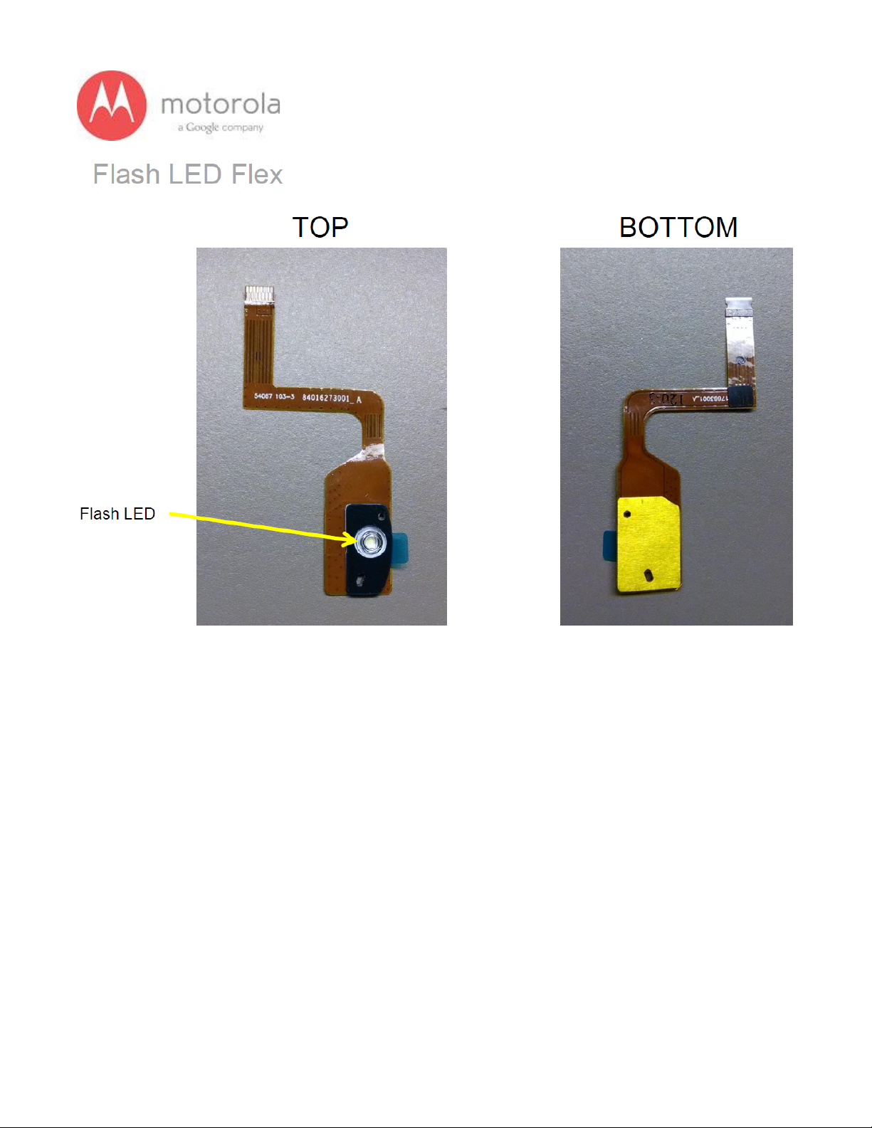
Flash LED Flex
Page 13
13
V1.2 Motorola Mobility Inc. Confidential Proprietary 10/02/2013
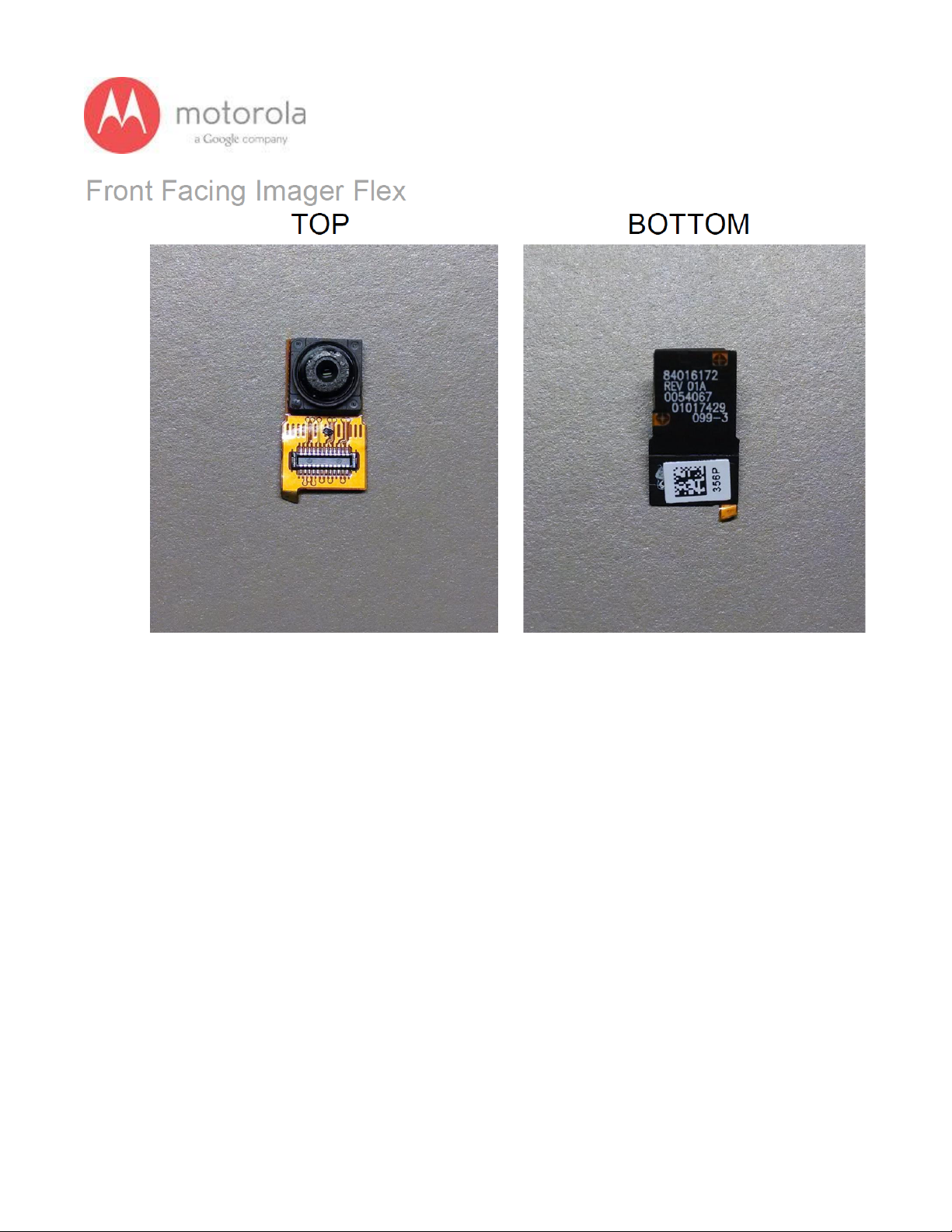
Front Facing Imager Flex
Page 14
14
V1.2 Motorola Mobility Inc. Confidential Proprietary 10/02/2013
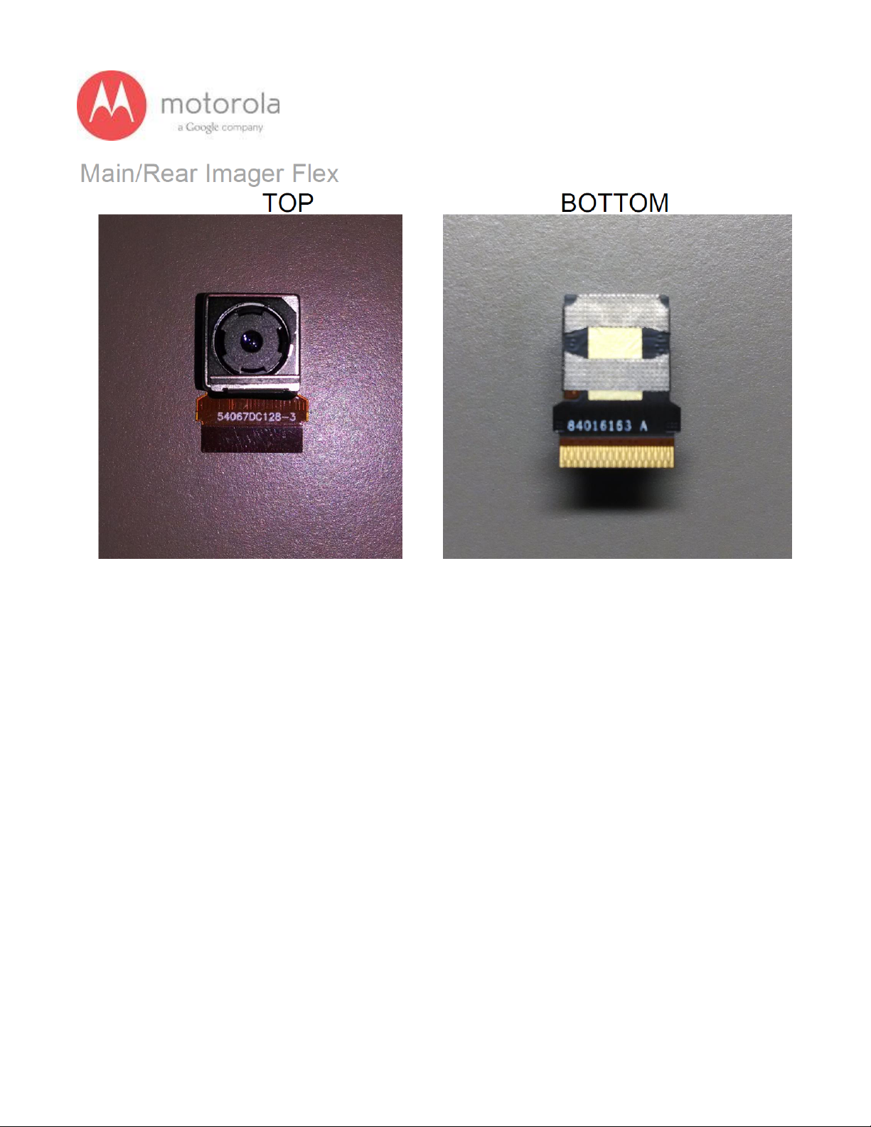
Main/Rear Imager Flex
Page 15
15
V1.2 Motorola Mobility Inc. Confidential Proprietary 10/02/2013
NFC Flex
Page 16
16
V1.2 Motorola Mobility Inc. Confidential Proprietary 10/02/2013
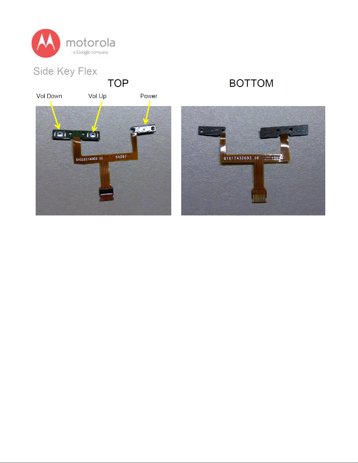
Side Key Flex
Page 17
17
V1.2 Motorola Mobility Inc. Confidential Proprietary 10/02/2013
5.0 RF Troubleshooting
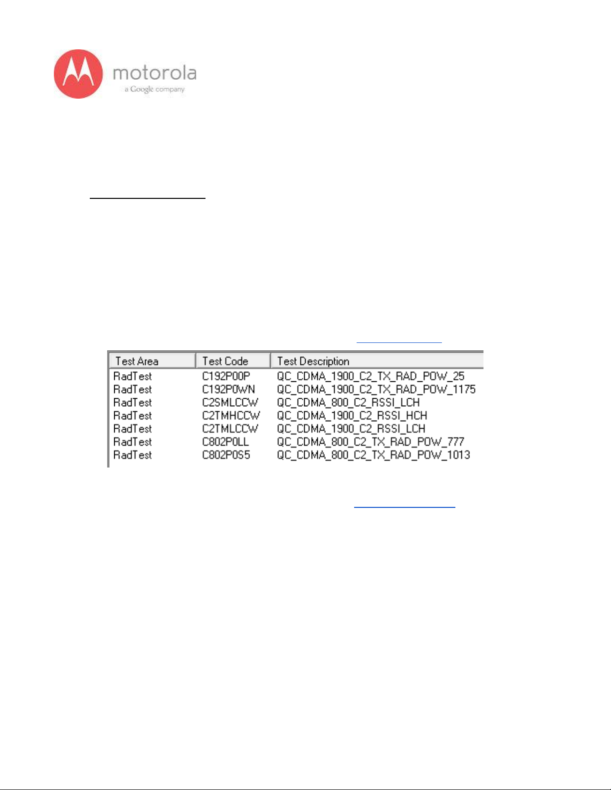
5.1.1 CDMA RF Troubleshooting
Objective / Purpose:
● Studying CDMA failures and providing procedure for debugging the failures
● The following tests from RADTEST section of the NTF_Pareto document will be
discussed
Here are the various test cases:
For the Verizon SKU Failure List (Primary, C0/C2): Verizon Primary
For the Verizon SKU Failure List (Secondary, C3): Verizon Secondary
● QC_CDMA_800_C3_RSSI_LCH
● QC_CDMA_1900_C3_RSSI_LCH
● QC_CDMA_1900_C3_RSSI_HCH
Page 18
18
V1.2 Motorola Mobility Inc. Confidential Proprietary 10/02/2013
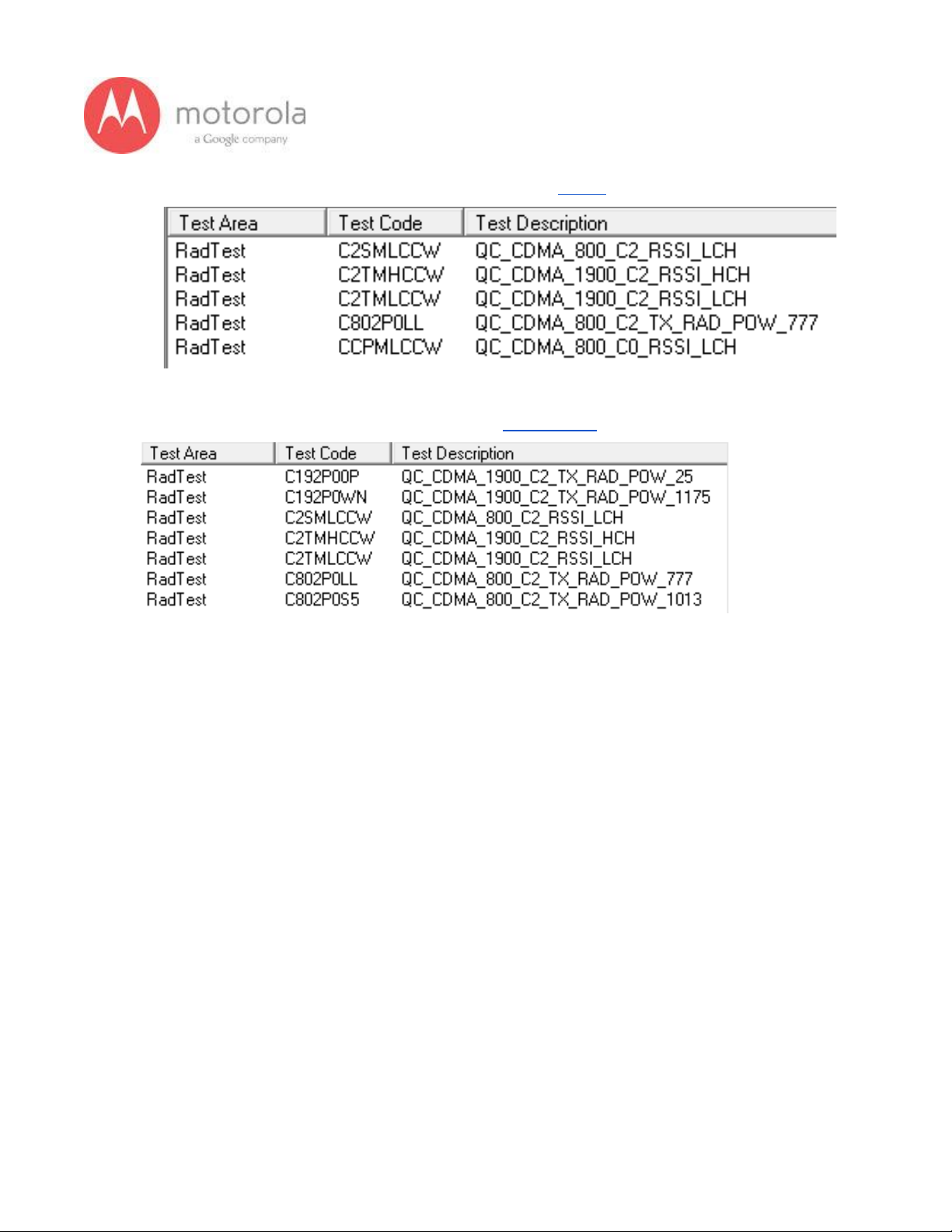
For the Sprint CDMA Failure List (Primary, C0/C2): Sprint Primary
For the USC SKU Failure List (Primary, C0): US Cellular
Page 19

19
V1.2 Motorola Mobility Inc. Confidential Proprietary 10/02/2013
Verizon CDMA Primary:
Please follow the detection scheme shown below to resolve the issue related to
VERIZON CDMA bands. If one step is not working then go to the next step.
Step 1: Repeat the test. If problem exists, go to the next step.
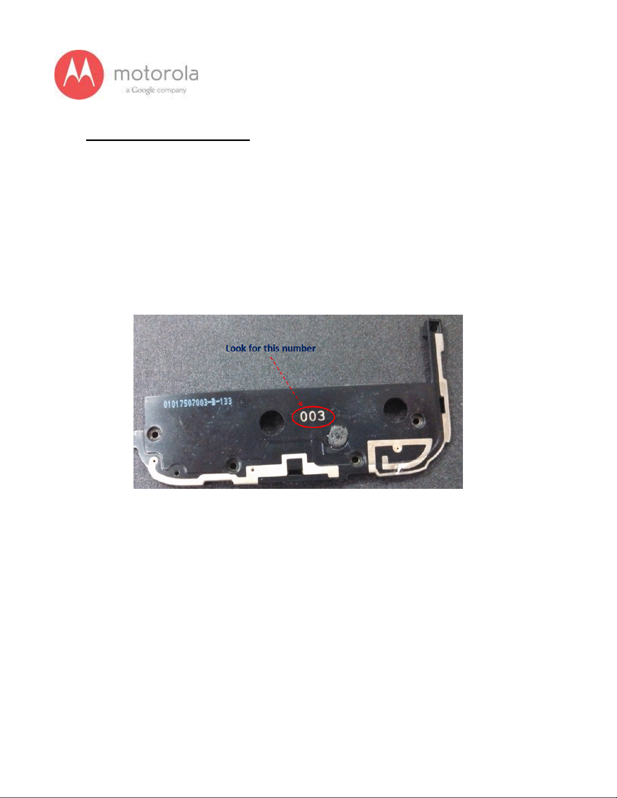
Step 2: Check if the bottom antenna carrier is for the Verizon or not. If it is Verizon,
003 is printed on the Antenna carrier as shown below:
Figure: Antenna Carrier
Page 20
20
V1.2 Motorola Mobility Inc. Confidential Proprietary 10/02/2013
Step 3: if Step 2 does not resolve issue, check if universal contact on the PCB is
damaged. Is it touching the antenna pad? If the contact is twisted or not making
contact, this is a problem. The contact should look like this picture below:
Figure: Antenna clip for CDMA Antenna
Page 21
21
V1.2 Motorola Mobility Inc. Confidential Proprietary 10/02/2013
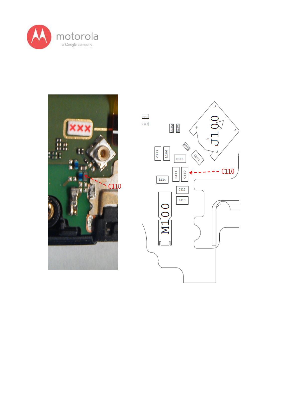
Step 4: If step 3 does not resolve the problem check if components C110 is placed
in the circuit
Figure: Component C110
Page 22
22
V1.2 Motorola Mobility Inc. Confidential Proprietary 10/02/2013
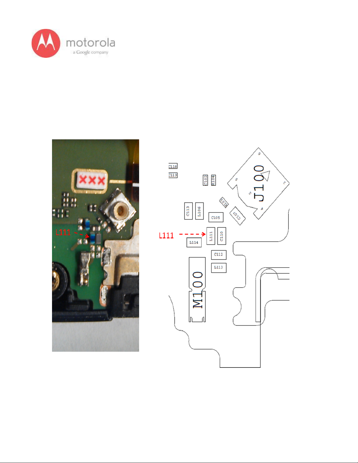
Step 5: If Step 4 does not resolve the problem check if components L111 is placed
in the circuit. In addition, you may have to check the component under a microscope
to ensure that the body of the part is not cracked.
Figure: Component L111
Page 23
23
V1.2 Motorola Mobility Inc. Confidential Proprietary 10/02/2013
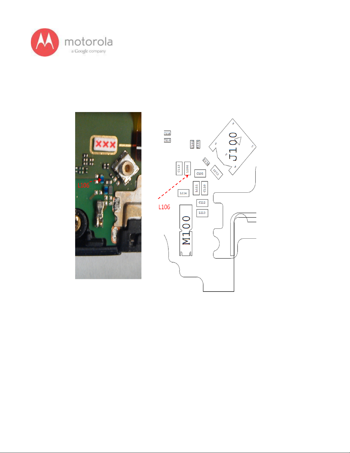
Step 6: If Step 5 does not resolve the problem check if components L106 is placed in
the circuit
Figure: Component L106
Page 24
24
V1.2 Motorola Mobility Inc. Confidential Proprietary 10/02/2013
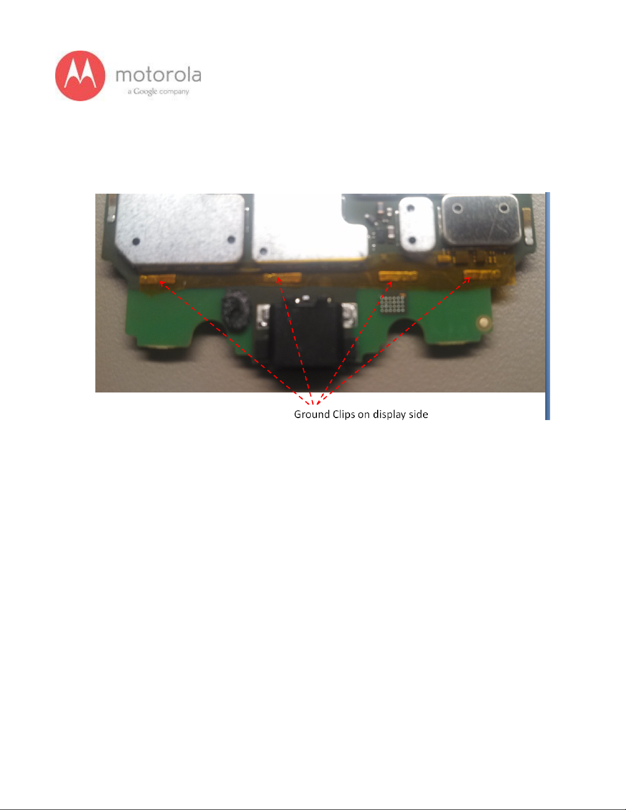
Step 7: If Step 6 does not resolve the problem check if the ground clips are placed on
the board
Figure: Moto X PCB board with ground clips
Page 25
25
V1.2 Motorola Mobility Inc. Confidential Proprietary 10/02/2013
Verizon CDMA Secondary
For factory radiated test failures on the Verizon SKU, for CDMA Secondary Bands
800 and 1900, please do the following:
Step 1: Retest the unit.
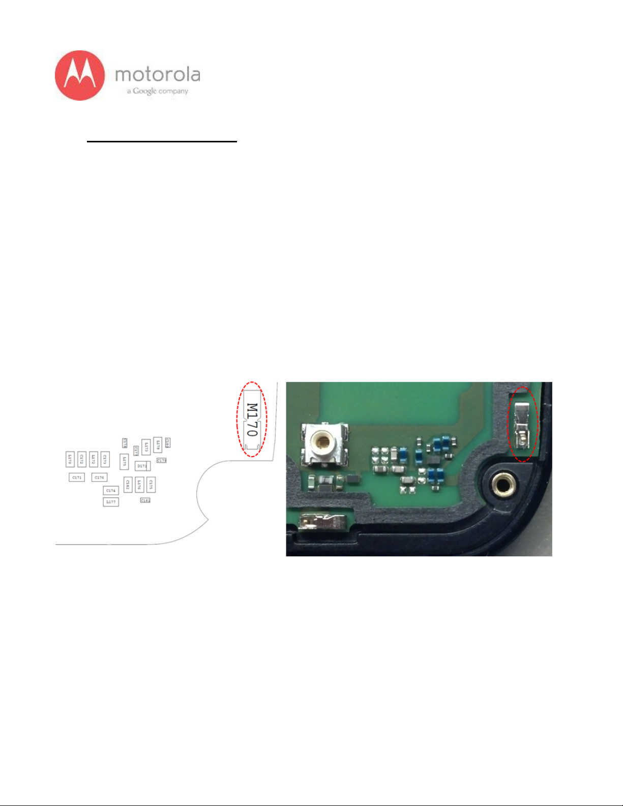
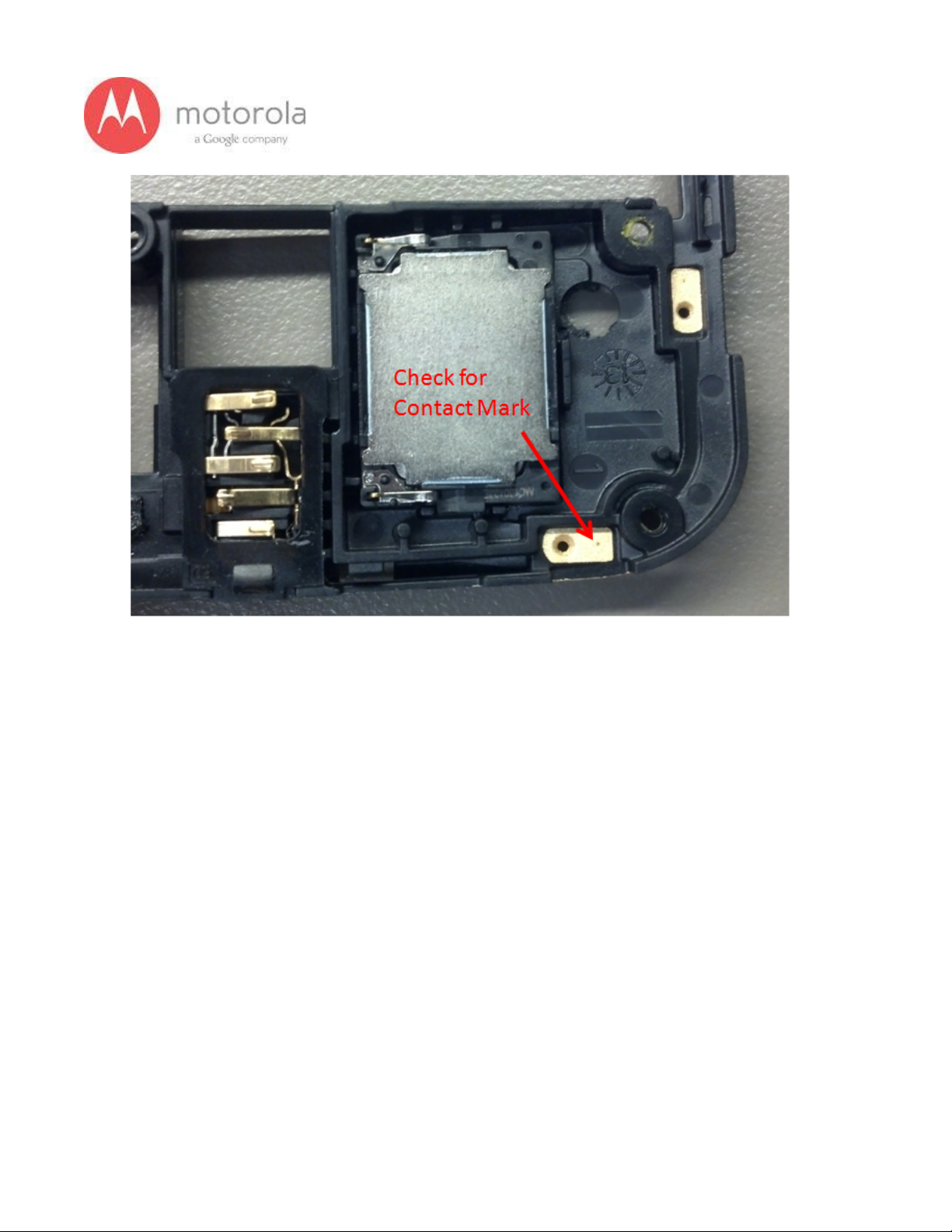
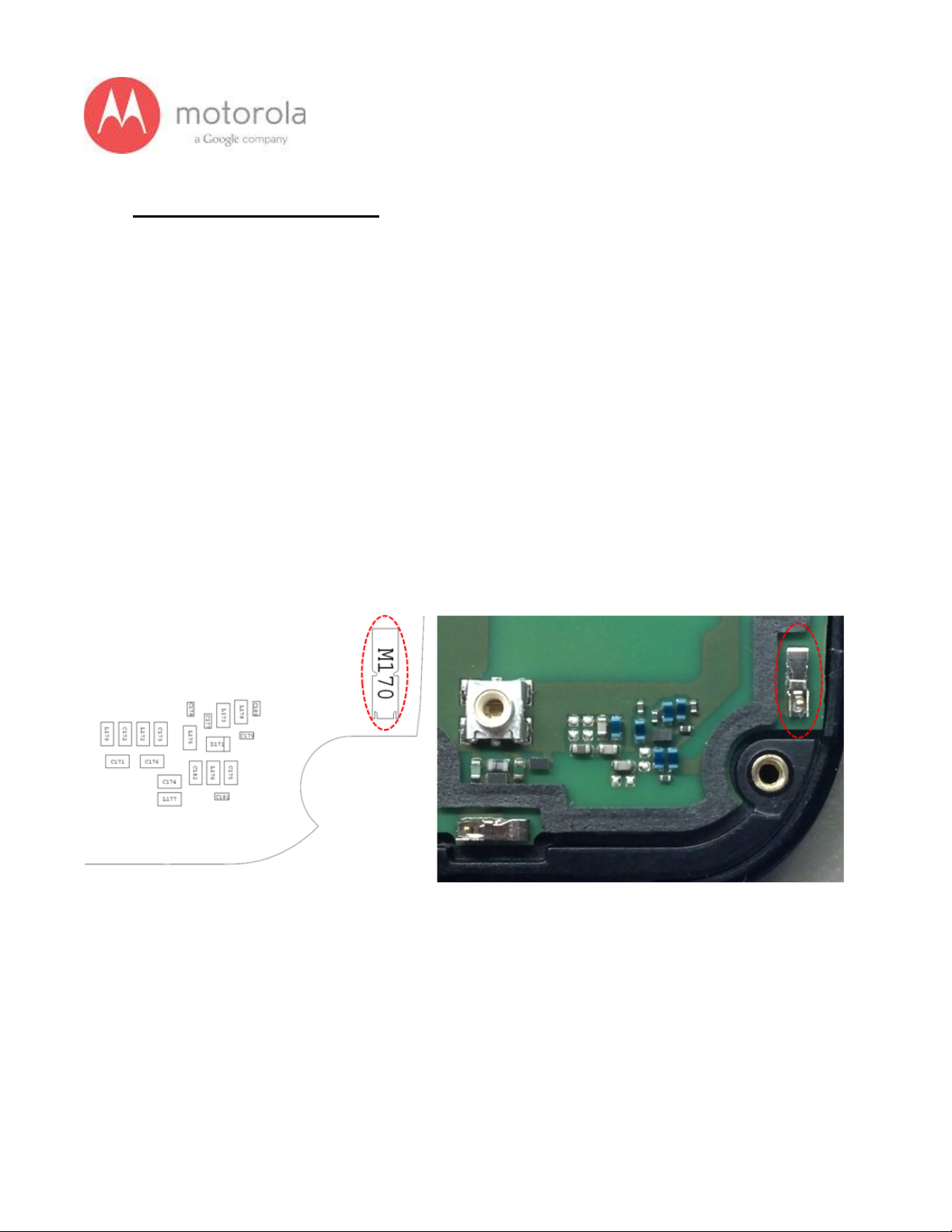
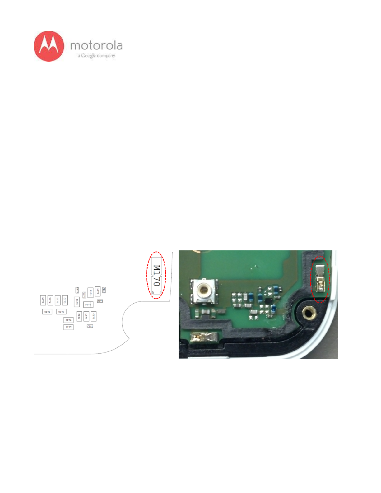
Step 2: If the failure persists, check the Antenna 3 universal contact, M170. If it is
missing, misplaced, or damaged, place/replace the part and retest. Also check the
contact pad of Antenna 3 on the diversity antenna carrier for a visible mark where the
contact was touching the pad. If no mark is present, replace the universal contact
M170 and retest.
Figure: Antenna 3 Universal Contact
Page 26
26
V1.2 Motorola Mobility Inc. Confidential Proprietary 10/02/2013
Figure: Contact Pad of Antenna 3
Page 27
27
V1.2 Motorola Mobility Inc. Confidential Proprietary 10/02/2013
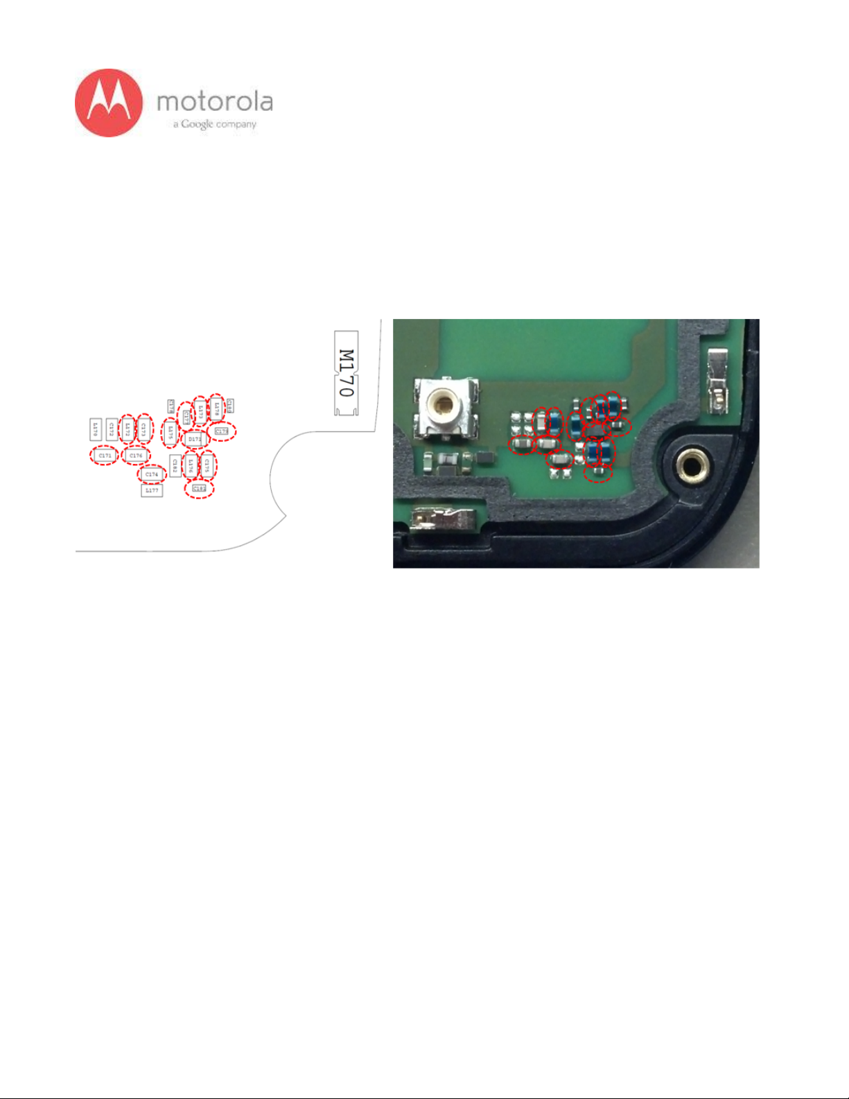
Step 3: If Step 2 does not resolve the issue, check all Antenna 3 matching
components and PIN diode biasing components: C171, L172, C176, C173, C174,
C181, C175, L176, L173, C177, D171, L175, L178, and C179. If any component is
missing, misplaced, or damaged, place/replace the part and retest.
Figure: Antenna 3 Matching Components and PIN Diode Biasing Components
Page 28
28
V1.2 Motorola Mobility Inc. Confidential Proprietary 10/02/2013
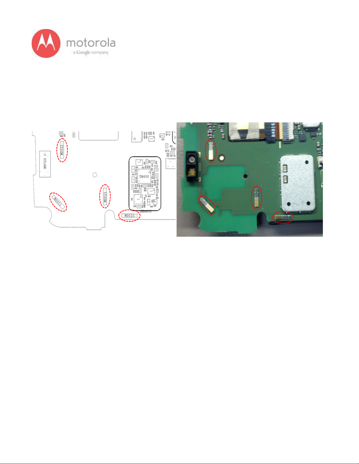
Step 4: If Step 3 does not resolve the issue, check the PCB grounding clips on the
display side of the PCB: M0010, M0011, M0012, and M0023. If any clip is missing,
misplaced, or damaged, place/replace the part and retest.
Figure: PCB Grounding Clips Near Antenna 3 Matching
Page 29
29
V1.2 Motorola Mobility Inc. Confidential Proprietary 10/02/2013
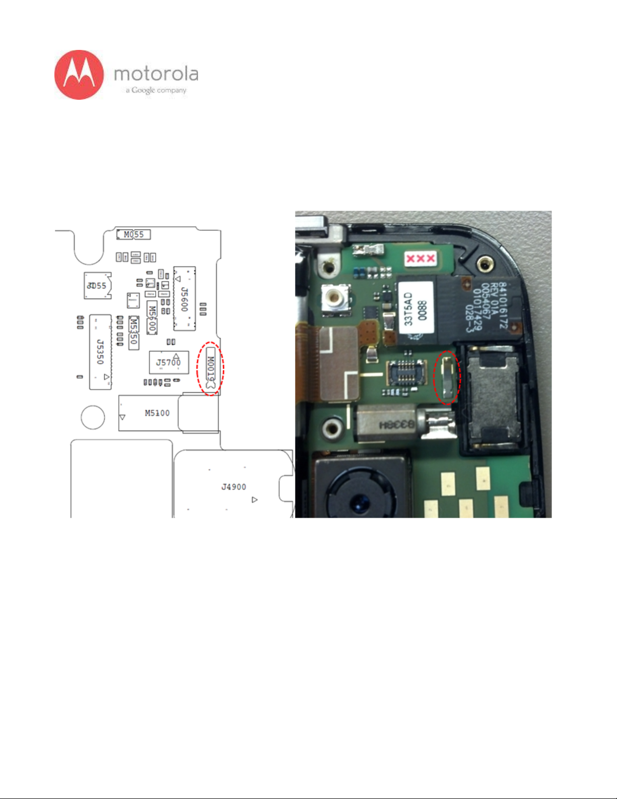
Step 5: If Step 4 does not resolve the issue, check the grounding clip between the
PCB and the audio flex bracket, M0019. If the clip is missing, misplaced, or
damaged, place/replace the part and retest.
Figure: Grounding Clip Between PCB and Audio Flex Bracket
Page 30
30
V1.2 Motorola Mobility Inc. Confidential Proprietary 10/02/2013
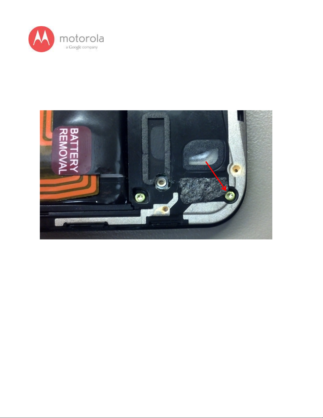
Step 6: If Step 5 does not resolve the issue, check the screw holding the antenna
carrier to the front housing near the Antenna 3 feed. If the screw is missing or not
fully inserted, place/replace the screw and retest.
Figure: Screw Holding Diversity Carrier near Antenna 3 Feed
Page 31

31
V1.2 Motorola Mobility Inc. Confidential Proprietary 10/02/2013
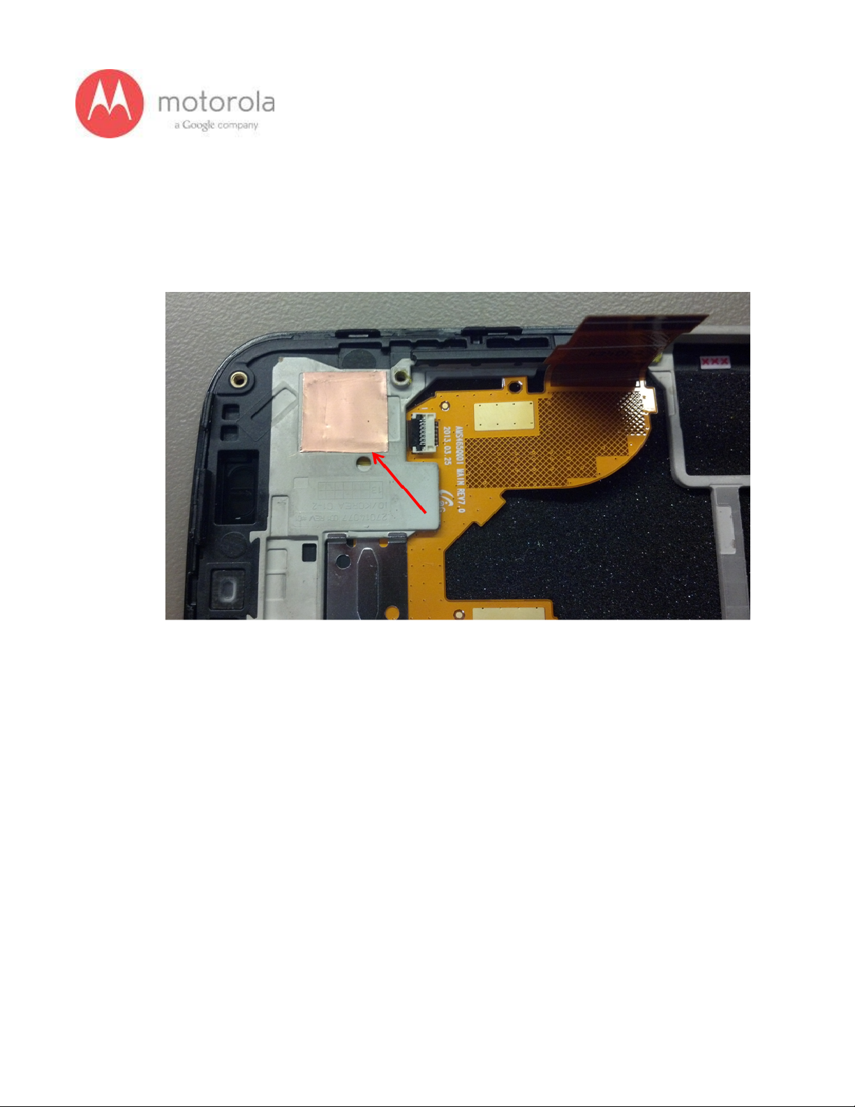
Step 7: If Step 6 does not resolve the issue, check the square piece of copper taped
placed over the touch IC on the chassis. If the copper tape is missing, misplaced, or
not fully adhered, place/replace the copper tape and retest.
Figure: Copper Tape over Touch IC on Chassis
Page 32

32
V1.2 Motorola Mobility Inc. Confidential Proprietary 10/02/2013
SPRINT CDMA:
Please follow the detection scheme shown below to resolve the issue related to
SPRINT CDMA bands. If one step is not working then go to the next step.
Step 1: Repeat the test. If problem exists, go to the next step.
Step 2: Check if the bottom antenna carrier is for the Sprint or not. If it is Sprint, 002
is printed on the Antenna carrier as shown below:
Step 3: Check if all the screws are present or not (see the picture below)
Page 33

33
V1.2 Motorola Mobility Inc. Confidential Proprietary 10/02/2013
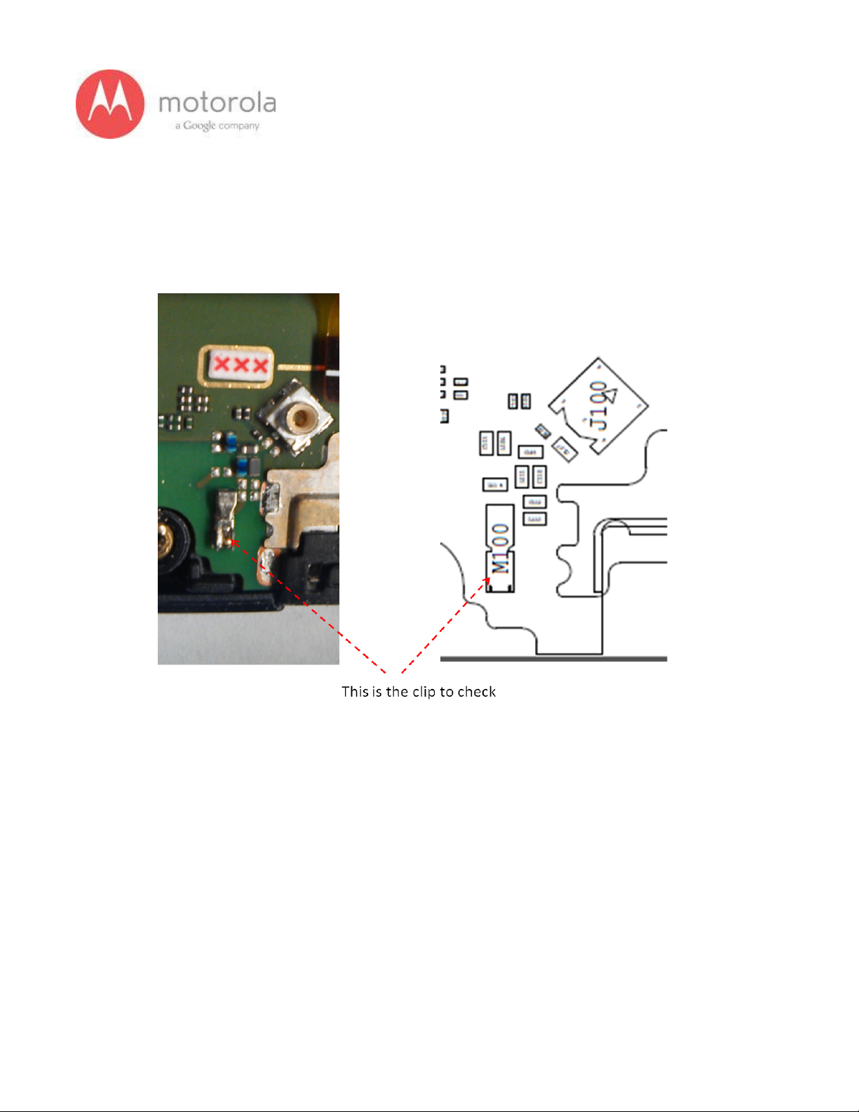
Step 4: Check if the antenna contact (M100) is present there or not. The location of
the contact is shown in the PCB layout below:
Page 34

34
V1.2 Motorola Mobility Inc. Confidential Proprietary 10/02/2013
Step 5: Check if the antenna feed for ANT1 is touching the antenna contact or not.
The photograph of the antenna feed area is shown below. You cannot see whether it
is touching or not, but if the carrier is touching you would see touch mark on the feed
of the antenna as shown below:
Page 35

35
V1.2 Motorola Mobility Inc. Confidential Proprietary 10/02/2013
Step 6: Check for the missing, misplaced, crashed parts for the following matching
components:
Page 36

36
V1.2 Motorola Mobility Inc. Confidential Proprietary 10/02/2013
Step 7: Check for the ground clips connecting display bezel to the PCB
Page 37

37
V1.2 Motorola Mobility Inc. Confidential Proprietary 10/02/2013
US Cellular CDMA Primary:
Please follow the detection scheme shown below to resolve the issue related to USC
CDMA bands. If one step is not working then go to the next step.
Step 1: Repeat the test. If problem exists, go to the next step.
Step 2: Check if the bottom antenna carrier is for the USC or not. If it is USC, 001 is
printed on the Antenna carrier as shown below:
Figure: Antenna Carrier
Page 38

38
V1.2 Motorola Mobility Inc. Confidential Proprietary 10/02/2013
Step 3: if Step 2 does not resolve issue. Check if the antenna feed for ANT1 is
touching the antenna contact or not. The photograph of the antenna feed area is
shown below. You cannot see whether it is touching or not, but if the carrier is
touching you would see touch mark on the feed of the antenna as shown below:
Figure: Antenna contact pad
Page 39

39
V1.2 Motorola Mobility Inc. Confidential Proprietary 10/02/2013
Step 4: If Step 3 fails, check if universal contact on the PCB is damaged. Is it
touching the antenna pad? If the contact is twisted or not making contact, this is a
problem. The contact should look like this picture below:
Figure: Antenna contact
Page 40

40
V1.2 Motorola Mobility Inc. Confidential Proprietary 10/02/2013
Step 5: If step 4 does not resolve the problem check if components L111, C110,
C107 and L106 are placed in the circuit.
Figure: Matching components
Page 41

41
V1.2 Motorola Mobility Inc. Confidential Proprietary 10/02/2013
Step 6: If Step 5 does not resolve the problem check if the ground clips are placed on
the board
Figure: Moto X PCB board with ground clips
Page 42

42
V1.2 Motorola Mobility Inc. Confidential Proprietary 10/02/2013
5.1.2 WCDMA/GSM RF Troubleshooting
Objective / Purpose:
● Studying WCDMA/GSM failures and providing procedure for debugging the
failures
● The following tests from RADTEST section of the NTF_Pareto document will be
discussed
Here are the various test cases :
For the AT&T SKU Failure List (Primary, C0): ATT Primary
● QC_WCDMA_2100C0_TX_RAD_POW_9888
● QC_WCDMA_1900_C0_TX_RAD_POW_9671
● QC_WCDMA_900_C0_RAD_RX_RSSI_LCH
● QC_WCDMA_1900_C0_TX_RAD_POW_9938
For the AT&T SKU Failure List (Secondary, C1): AT&T Secondary
● QC_WCDMA_850_C1_RAD_RX_RSSI_LCH
● QC_WCDMA_850_C1_RAD_RX_RSSI_HCH
● QC_WCDMA_900_C1_RAD_RX_RSSI_LCH
● QC_WCDMA_900_C1_RAD_RX_RSSI_HCH
● QC_WCDMA_1900_C1_RAD_RX_RSSI_LCH
● QC_WCDMA_1900_C1_RAD_RX_RSSI_HCH
● QC_WCDMA_2100_C1_RAD_RX_RSSI_LCH
● QC_WCDMA_2100_C1_RAD_RX_RSSI_HCH
For the Verizon SKU Failure List (Primary, C0): Verizon Primary
● QC_WCDMA_1900_C0_RAD_RX_RSSI_HCH
● QC_WCDMA_1900_C0_RAD_RX_RSSI_LCH
● QC_WCDMA_2100C0_TX_RAD_POW_9612
Page 43

43
V1.2 Motorola Mobility Inc. Confidential Proprietary 10/02/2013
● QC_WCDMA_2100C0_TX_RAD_POW_9888
● QC_WCDMA_2100_C0_RAD_RX_RSSI_HCH
● QC_WCDMA_2100_C0_RAD_RX_RSSI_LCH
● QC_WCDMA_850C0_TX_RAD_POW_4133
● QC_WCDMA_850C0_TX_RAD_POW_4233
● QC_WCDMA_850_C0_RAD_RX_RSSI_HCH
● QC_WCDMA_850_C0_RAD_RX_RSSI_LCH
● QC_WCDMA_900C0_TX_RAD_POW_2712
● QC_WCDMA_900C0_TX_RAD_POW_2863
● QC_WCDMA_900_C0_RAD_RX_RSSI_HCH
● QC_WCDMA_900_C0_RAD_RX_RSSI_LCH
For the Verizon SKU Failure List (Secondary, C1): Verizon Secondary
● QC_WCDMA_850_C1_RAD_RX_RSSI_LCH
● QC_WCDMA_850_C1_RAD_RX_RSSI_HCH
● QC_WCDMA_900_C1_RAD_RX_RSSI_LCH
● QC_WCDMA_900_C1_RAD_RX_RSSI_HCH
● QC_WCDMA_1900_C1_RAD_RX_RSSI_LCH
● QC_WCDMA_1900_C1_RAD_RX_RSSI_HCH
● QC_WCDMA_2100_C1_RAD_RX_RSSI_LCH
● QC_WCDMA_2100_C1_RAD_RX_RSSI_HCH
For the Sprint WCDMA Failure List (Primary, C0): Sprint Primary
● W19HHCCW: QC_WCDMA_1900_C0_RAD_RX_RSSI_HCH
● W19LHCCW: QC_WCDMA_1900_C0_RAD_RX_RSSI_LCH
● W21MHCCW: QC_WCDMA_2100_C0_RAD_RX_RSSI_HCH
● W21MLCCW: QC_WCDMA_2100_C0_RAD_RX_RSSI_LCH
For the Sprint SKU Failure List (Secondary, C1): Sprint Secondary
Page 44

44
V1.2 Motorola Mobility Inc. Confidential Proprietary 10/02/2013
● QC_WCDMA_1900_C1_RAD_RX_RSSI_LCH
● QC_WCDMA_1900_C1_RAD_RX_RSSI_HCH
● QC_WCDMA_2100_C1_RAD_RX_RSSI_LCH
● QC_WCDMA_2100_C1_RAD_RX_RSSI_HCH
For the USC SKU Failure List (Primary, C0): US Cellular Primary
● QC_LTE_BC5_C0_RX_RAD_RSSI_LCH2450
For the T-Mobile SKU Failure List (Secondary, C1): T-Mobile Secondary
● QC_WCDMA_850_C1_RAD_RX_RSSI_LCH
● QC_WCDMA_850_C1_RAD_RX_RSSI_HCH
● QC_WCDMA_900_C1_RAD_RX_RSSI_LCH
● QC_WCDMA_900_C1_RAD_RX_RSSI_HCH
● QC_WCDMA_1700_C1_RAD_RX_RSSI_LCH
● QC_WCDMA_1700_C1_RAD_RX_RSSI_HCH
● QC_WCDMA_1900_C1_RAD_RX_RSSI_LCH
● QC_WCDMA_1900_C1_RAD_RX_RSSI_HCH
● QC_WCDMA_2100_C1_RAD_RX_RSSI_LCH
● QC_WCDMA_2100_C1_RAD_RX_RSSI_HCH
Page 45

45
V1.2 Motorola Mobility Inc. Confidential Proprietary 10/02/2013
AT&T GSM / WCDMA Primary
For factory radiated test failure on AT&T SKU at GSM / WCDMA bands, please do
the following:
Step 1: Retest
Step 2: If retest does not pass, check if the unit has correct bottom antenna carrier.
The AT&T bottom antenna carrier should look like following:
Fig: Moto X Americas Bottom Antenna Carrier
Page 46

46
V1.2 Motorola Mobility Inc. Confidential Proprietary 10/02/2013
Step 3: if Step 2 does not resolve issue, check if universal contact (RefDes = M100)
on the PCB is damaged. Is it touching the antenna pad? If the universal clip is
twisted or not making contact, this needs to be replaced :
Figure: Contact marks visible on feeding pad from universal clip for WCDMA Antenna
Page 47

47
V1.2 Motorola Mobility Inc. Confidential Proprietary 10/02/2013
Step 4: If Step 3 does not resolve the problem check if components RefDes = L106,
L111, C107 and C110 are placed correctly on PCB as shown below:
Figure: Antenna matching components and universal clip for WCDMA Antenna
Page 48

48
V1.2 Motorola Mobility Inc. Confidential Proprietary 10/02/2013
AT&T WCDMA Secondary
For factory radiated test failures on the AT&T SKU, for WCDMA Secondary Rx
Bands 850, 900, 1900, and 2100, please do the following:
Step 1: Retest the unit.
Step 2: If the failure persists, check the Antenna 3 universal contact, M170. If it is
missing, misplaced, or damaged, place/replace the part and retest. Also check the
contact pad of Antenna 3 on the diversity antenna carrier for a visible mark where the
contact was touching the pad. If no mark is present, replace the universal contact
M170 and retest.
Figure: Antenna 3 Universal Contact
Page 49

49
V1.2 Motorola Mobility Inc. Confidential Proprietary 10/02/2013
Figure: Contact Pad of Antenna 3
Page 50

50
V1.2 Motorola Mobility Inc. Confidential Proprietary 10/02/2013
Step 3: If Step 2 does not resolve the issue, check all Antenna 3 matching
components and PIN diode biasing components: C171, L172, C176, C173, C174,
C181, C175, L176, L173, C177, D171, L175, L178, and C179. If any component is
missing, misplaced, or damaged, place/replace the part and retest.
Figure: Antenna 3 Matching Components and PIN Diode Biasing Components
Page 51

51
V1.2 Motorola Mobility Inc. Confidential Proprietary 10/02/2013
Step 4: If Step 3 does not resolve the issue, check the PCB grounding clips on the
display side of the PCB: M0010, M0011, M0012, and M0023. If any clip is missing,
misplaced, or damaged, place/replace the part and retest.
Figure: PCB Grounding Clips Near Antenna 3 Matching
Page 52

52
V1.2 Motorola Mobility Inc. Confidential Proprietary 10/02/2013
Step 5: If Step 4 does not resolve the issue, check the grounding clip between the
PCB and the audio flex bracket, M0019. If the clip is missing, misplaced, or
damaged, place/replace the part and retest.
Figure: Grounding Clip Between PCB and Audio Flex Bracket
Page 53

53
V1.2 Motorola Mobility Inc. Confidential Proprietary 10/02/2013
Step 6: If Step 5 does not resolve the issue, check the screw holding the antenna
carrier to the front housing near the Antenna 3 feed. If the screw is missing or not
fully inserted, place/replace the screw and retest.
Figure: Screw Holding Diversity Carrier near Antenna 3 Feed
Page 54

54
V1.2 Motorola Mobility Inc. Confidential Proprietary 10/02/2013
Step 7: If Step 6 does not resolve the issue, check the square piece of copper taped
placed over the touch IC on the chassis. If the copper tape is missing, misplaced, or
not fully adhered, place/replace the copper tape and retest.
Figure: Copper Tape over Touch IC on Chassis
Page 55
55
V1.2 Motorola Mobility Inc. Confidential Proprietary 10/02/2013
VZW GSM / WCDMA Primary
If this test fails in factory these are the steps to take
Step 1: Please retest the unit again
Step 2: If failure persists, check if we have the right carrier. The carrier is as shown in
figure below
Fig: Carrier
Page 56

56
V1.2 Motorola Mobility Inc. Confidential Proprietary 10/02/2013
Step 3: if Step 2 does not resolve issue, check if universal contact on the PCB is
damaged. Is it touching the antenna pad? If the contact is twisted or not making
contact, this is a problem. The contact should look like this picture below:
Figure: Antenna clip for WCDMA Antenna
Page 57

57
V1.2 Motorola Mobility Inc. Confidential Proprietary 10/02/2013
Step 4: If step 3 does not resolve the problem check if components C110 is placed
in the circuit
Figure: Component C110
Page 58

58
V1.2 Motorola Mobility Inc. Confidential Proprietary 10/02/2013
Step 5: If Step 4 does not resolve the problem check if components L111
Figure: Component L111
Page 59

59
V1.2 Motorola Mobility Inc. Confidential Proprietary 10/02/2013
Step 6: If Step 5 does not resolve the problem check if components L106 is placed in
the circuit
Figure: Component L106
Page 60

60
V1.2 Motorola Mobility Inc. Confidential Proprietary 10/02/2013
Step 7: If Step 6 does not resolve the problem check if the ground clips are placed on
the board
Figure: Moto X PCB board with ground clips
Page 61
61
V1.2 Motorola Mobility Inc. Confidential Proprietary 10/02/2013
Verizon WCDMA Secondary
For factory radiated test failures on the Verizon SKU, for WCDMA Secondary Rx
Bands 850, 900, 1900, and 2100, please do the following:
Step 1: Retest the unit.
Step 2: If the failure persists, check the Antenna 3 universal contact, M170. If it is
missing, misplaced, or damaged, place/replace the part and retest. Also check the
contact pad of Antenna 3 on the diversity antenna carrier for a visible mark where the
contact was touching the pad. If no mark is present, replace the universal contact
M170 and retest.
Figure: Antenna 3 Universal Contact
Page 62

62
V1.2 Motorola Mobility Inc. Confidential Proprietary 10/02/2013
Figure: Contact Pad of Antenna 3
Page 63

63
V1.2 Motorola Mobility Inc. Confidential Proprietary 10/02/2013
Step 3: If Step 2 does not resolve the issue, check all Antenna 3 matching
components and PIN diode biasing components: C171, L172, C176, C173, C174,
C181, C175, L176, L173, C177, D171, L175, L178, and C179. If any component is
missing, misplaced, or damaged, place/replace the part and retest.
Figure: Antenna 3 Matching Components and PIN Diode Biasing Components
Page 64

64
V1.2 Motorola Mobility Inc. Confidential Proprietary 10/02/2013
Step 4: If Step 3 does not resolve the issue, check the PCB grounding clips on the
display side of the PCB: M0010, M0011, M0012, and M0023. If any clip is missing,
misplaced, or damaged, place/replace the part and retest.
Figure: PCB Grounding Clips Near Antenna 3 Matching
Page 65

65
V1.2 Motorola Mobility Inc. Confidential Proprietary 10/02/2013
Step 5: If Step 4 does not resolve the issue, check the grounding clip between the
PCB and the audio flex bracket, M0019. If the clip is missing, misplaced, or
damaged, place/replace the part and retest.
Figure: Grounding Clip Between PCB and Audio Flex Bracket
Page 66

66
V1.2 Motorola Mobility Inc. Confidential Proprietary 10/02/2013
Step 6: If Step 5 does not resolve the issue, check the screw holding the antenna
carrier to the front housing near the Antenna 3 feed. If the screw is missing or not
fully inserted, place/replace the screw and retest.
Figure: Screw Holding Diversity Carrier near Antenna 3 Feed
Page 67

67
V1.2 Motorola Mobility Inc. Confidential Proprietary 10/02/2013
Step 7: If Step 6 does not resolve the issue, check the square piece of copper taped
placed over the touch IC on the chassis. If the copper tape is missing, misplaced, or
not fully adhered, place/replace the copper tape and retest.
Figure: Copper Tape over Touch IC on Chassis
Page 68

68
V1.2 Motorola Mobility Inc. Confidential Proprietary 10/02/2013
USC WCDMA Primary:
SPRINT WCDMA Primary:
Please follow the detection scheme shown below to resolve the issue related to
SPRINT WCDMA/GSM bands. If one step is not working then go to the next step
Step 1: Repeat the test. If problem exists, go to the next step.
Step 2: Check if the bottom antenna carrier is for the Sprint or not. If it is Sprint, 002
is printed on the Antenna carrier as shown below:
Page 69

69
V1.2 Motorola Mobility Inc. Confidential Proprietary 10/02/2013
Step 3: Check if all the screws are present or not (see the picture below)
Page 70

70
V1.2 Motorola Mobility Inc. Confidential Proprietary 10/02/2013
Step 4: Check if the antenna contact (M100) is present there or not. The location of
the contact is shown in the PCB layout below:
Page 71

71
V1.2 Motorola Mobility Inc. Confidential Proprietary 10/02/2013
Step 5: Check if the antenna feed for ANT1 is touching the antenna contact or not.
The photograph of the antenna feed area is shown below. You cannot see whether it
is touching or not, but if the carrier is touching you would see touch mark on the feed
of the antenna as shown below:
Page 72

72
V1.2 Motorola Mobility Inc. Confidential Proprietary 10/02/2013
Step 6: Check for the missing, misplaced, crashed parts for the following matching
components:
Page 73

73
V1.2 Motorola Mobility Inc. Confidential Proprietary 10/02/2013
Step 7: Check for the ground clips connecting display bezel to the PCB
Page 74

74
V1.2 Motorola Mobility Inc. Confidential Proprietary 10/02/2013
Sprint WCDMA Secondary
For factory radiated test failures on the Sprint SKU, for WCDMA Secondary Rx
Bands 1900 and 2100, please do the following:
Step 1: Retest the unit.
Step 2: If the failure persists, check the Antenna 3 universal contact, M170. If it is
missing, misplaced, or damaged, place/replace the part and retest. Also check the
contact pad of Antenna 3 on the diversity antenna carrier for a visible mark where the
contact was touching the pad. If no mark is present, replace the universal contact
M170 and retest.
Figure: Antenna 3 Universal Contact
Page 75

75
V1.2 Motorola Mobility Inc. Confidential Proprietary 10/02/2013
Figure: Contact Pad of Antenna 3
Page 76

76
V1.2 Motorola Mobility Inc. Confidential Proprietary 10/02/2013
Step 3: If Step 2 does not resolve the issue, check all Antenna 3 matching
components and PIN diode biasing components: C171, L172, C176, C173, C174,
C181, and C175. If any component is missing, misplaced, or damaged, place/replace
the part and retest.
Figure: Antenna 3 Matching Components and PIN Diode Biasing Components
Page 77

77
V1.2 Motorola Mobility Inc. Confidential Proprietary 10/02/2013
Step 4: If Step 3 does not resolve the issue, check the PCB grounding clips on the
display side of the PCB: M0010, M0011, M0012, and M0023. If any clip is missing,
misplaced, or damaged, place/replace the part and retest.
Figure: PCB Grounding Clips Near Antenna 3 Matching
Page 78

78
V1.2 Motorola Mobility Inc. Confidential Proprietary 10/02/2013
Step 5: If Step 4 does not resolve the issue, check the grounding clip between the
PCB and the audio flex bracket, M0019. If the clip is missing, misplaced, or
damaged, place/replace the part and retest.
Figure: Grounding Clip Between PCB and Audio Flex Bracket
Page 79

79
V1.2 Motorola Mobility Inc. Confidential Proprietary 10/02/2013
Step 6: If Step 5 does not resolve the issue, check the screw holding the antenna
carrier to the front housing near the Antenna 3 feed. If the screw is missing or not
fully inserted, place/replace the screw and retest.
Figure: Screw Holding Diversity Carrier near Antenna 3 Feed
Page 80

80
V1.2 Motorola Mobility Inc. Confidential Proprietary 10/02/2013
Step 7: If Step 6 does not resolve the issue, check the square piece of copper taped
placed over the touch IC on the chassis. If the copper tape is missing, misplaced, or
not fully adhered, place/replace the copper tape and retest.
Figure: Copper Tape over Touch IC on Chassis
Page 81

81
V1.2 Motorola Mobility Inc. Confidential Proprietary 10/02/2013
T-Mobile WCDMA Primary
For factory radiated test failures on the T-Mobile SKU, for WCDMA Primary Bands 2,
4, and 5. please do the following:
Step 1: Retest the unit.
Step 2: Check if the bottom antenna carrier is the correct carrier for TMO. TMO
antenna has marking ‘004’ as shown below
Page 82

82
V1.2 Motorola Mobility Inc. Confidential Proprietary 10/02/2013
Step 3: If the failure persists, check the Antenna 1 universal contact, M100. If it is
missing, misplaced, or damaged, place/replace the part and retest. Also check the
contact pad of Antenna 2 on the main antenna carrier for a visible mark where the
contact was touching the pad. If no mark is present, replace the universal contact
M100 and retest.
Page 83

83
V1.2 Motorola Mobility Inc. Confidential Proprietary 10/02/2013
Step 4: If Step 3 does not resolve the issue, check all Antenna 1 matching
components L113, C110, C107 and C105. If any component is missing, misplaced,
or damaged, place/replace the part and retest.
Page 84

84
V1.2 Motorola Mobility Inc. Confidential Proprietary 10/02/2013
Step 5: If Step 4 does not resolve the issue, check the PCB grounding clips on the
display side of the PCB: M0005, M0022, M0021, and M0006. If any clip is missing,
misplaced, or damaged, place/replace the part and retest.
Step 6: If Step 5 does not resolve the issue, check the screw holding the antenna
carrier to the front housing near the Antenna 1 feed. If the screw is missing or not
fully inserted, place/replace the screw and retest.
Page 85
85
V1.2 Motorola Mobility Inc. Confidential Proprietary 10/02/2013
T-Mobile WCDMA Secondary
For factory radiated test failures on the T-Mobile SKU, for WCDMA Secondary Rx
Bands 850, 900, 1700, 1900, and 2100, please do the following:
Step 1: Retest the unit.
Step 2: If the failure persists, check the Antenna 3 universal contact, M170. If it is
missing, misplaced, or damaged, place/replace the part and retest. Also check the
contact pad of Antenna 3 on the diversity antenna carrier for a visible mark where the
contact was touching the pad. If no mark is present, replace the universal contact
M170 and retest.
Figure: Antenna 3 Universal Contact
Page 86

86
V1.2 Motorola Mobility Inc. Confidential Proprietary 10/02/2013
Figure: Contact Pad of Antenna 3
Page 87

87
V1.2 Motorola Mobility Inc. Confidential Proprietary 10/02/2013
Step 3: If Step 2 does not resolve the issue, check all Antenna 3 matching
components and PIN diode biasing components: C171, L172, C176, C173, C174,
C181, and C175. If any component is missing, misplaced, or damaged, place/replace
the part and retest.
Figure: Antenna 3 Matching Components and PIN Diode Biasing Components
Page 88

88
V1.2 Motorola Mobility Inc. Confidential Proprietary 10/02/2013
Step 4: If Step 3 does not resolve the issue, check the PCB grounding clips on the
display side of the PCB: M0010, M0011, M0012, and M0023. If any clip is missing,
misplaced, or damaged, place/replace the part and retest.
Figure: PCB Grounding Clips Near Antenna 3 Matching
Page 89

89
V1.2 Motorola Mobility Inc. Confidential Proprietary 10/02/2013
Step 5: If Step 4 does not resolve the issue, check the grounding clip between the
PCB and the audio flex bracket, M0019. If the clip is missing, misplaced, or
damaged, place/replace the part and retest.
Figure: Grounding Clip Between PCB and Audio Flex Bracket
Page 90

90
V1.2 Motorola Mobility Inc. Confidential Proprietary 10/02/2013
Step 6: If Step 5 does not resolve the issue, check the screw holding the antenna
carrier to the front housing near the Antenna 3 feed. If the screw is missing or not
fully inserted, place/replace the screw and retest.
Figure: Screw Holding Diversity Carrier near Antenna 3 Feed
Page 91
91
V1.2 Motorola Mobility Inc. Confidential Proprietary 10/02/2013
Step 7: If Step 6 does not resolve the issue, check the square piece of copper taped
placed over the touch IC on the chassis. If the copper tape is missing, misplaced, or
not fully adhered, place/replace the copper tape and retest.
Figure: Copper Tape over Touch IC on Chassis
Page 92

92
V1.2 Motorola Mobility Inc. Confidential Proprietary 10/02/2013
5.1.3 LTE RF Troubleshooting
Objective / Purpose:
● Studying LTE Band failures and providing procedure for debugging the failures
● The following tests from RADTEST section of the NTF_Pareto document will be
discussed
Here are the various test cases :
For the AT&T SKU Failure List (Primary, C0): AT&T Primary
● QC_LTE_BC17_C0_TX_RAD_POW_23780
● QC_LTE_BC7_C0_RX_RAD_RSSI_HCH3400
For the AT&T SKU Failure List (Secondary, C1): AT&T Secondary
● QC_LTE_BC2_C1_RX_RAD_RSSI_LCH650
● QC_LTE_BC2_C1_RX_RAD_RSSI_HCH1150 SW see
● QC_LTE_BC4_C1_RX_RAD_RSSI_LCH2000
● QC_LTE_BC4_C1_RX_RAD_RSSI_HCH2350
● QC_LTE_BC5_C1_RX_RAD_RSSI_LCH2450
● QC_LTE_BC5_C1_RX_RAD_RSSI_HCH2600
● QC_LTE_BC7_C1_RX_RAD_RSSI_LCH2800
● QC_LTE_BC7_C1_RX_RAD_RSSI_HCH3400
● QC_LTE_BC17_C1_RX_RAD_RSSI_LCH5780
● QC_LTE_BC17_C1_RX_RAD_RSSI_HCH5800
For the Verizon SKU Failure List (Primary, C0): Verizon Primary
● QC_LTE_BC13_C0_Rx_RAD_RSSI_LCH5184
● QC_LTE_BC13_C0_RX_RAD_RSSI_HCH5268
● QC_LTE_BC13_C0_TX_RAD_POW_23230
Page 93

93
V1.2 Motorola Mobility Inc. Confidential Proprietary 10/02/2013
● QC_LTE_BC04_C0_TX_RAD_POW_20350
● QC_LTE_BC04_C0_TX_RAD_POW_20000
For the Verizon SKU Failure List (Secondary, C1): Verizon Secondary
● QC_LTE_BC4_C1_RX_RAD_RSSI_LCH2000
● QC_LTE_BC4_C1_RX_RAD_RSSI_HCH2350
● QC_LTE_BC13_C1_RX_RAD_RSSI_LCH5184
● QC_LTE_BC13_C1_RX_RAD_RSSI_HCH5268
For the USC SKU Failure List (Primary, C0): US Cellular Primary
● QC_LTE_BC04_C0_TX_RAD_POW_20000
● QC_LTE_BC04_C0_TX_RAD_POW_20350
● QC_LTE_BC05_C0_TX_RAD_POW_20450
● QC_LTE_BC05_C0_TX_RAD_POW_20600
● QC_LTE_BC05_C0_TX_RAD_POW_23060
● QC_LTE_BC12_C0_TX_RAD_POW_23130
● QC_LTE_BC12_C0_RX_RAD_RSSI_HCH5130
● QC_LTE_BC12_C0_RX_RAD_RSSI_LCH5060
● QC_LTE_BC5_C0_RX_RAD_RSSI_HCH2600
● QC_LTE_BC5_C0_RX_RAD_RSSI_LCH2450
For the USC SKU Failure List (Secondary, C1): US Cellular Secondary
● QC_LTE_BC4_C1_RX_RAD_RSSI_LCH2000
● QC_LTE_BC4_C1_RX_RAD_RSSI_HCH2350
● QC_LTE_BC5_C1_RX_RAD_RSSI_LCH2450
● QC_LTE_BC5_C1_RX_RAD_RSSI_HCH2600
● QC_LTE_BC12_C1_RX_RAD_RSSI_LCH5060
● QC_LTE_BC12_C1_RX_RAD_RSSI_HCH5130
Page 94

94
V1.2 Motorola Mobility Inc. Confidential Proprietary 10/02/2013
For the Sprint SKU Failure List (Primary, C0): SPRINT Primary
L250PCFC QC_LTE_BC25_C0_TX_RAD_POW_26090
L250PDAG QC_LTE_BC25_C0_TX_RAD_POW_26090
LP0RMBP4 QC_LTE_BC25_C0_RX_RAD_RSSI_LCH_8090
LP0RMCK8 QC_LTE_BC25_C0_RX_RAD_RSSI_HCH_8640
For the T-Mobile SKU Failure List (Secondary, C1): T-Mobile Secondary
● QC_LTE_BC2_C1_RX_RAD_RSSI_LCH650
● QC_LTE_BC2_C1_RX_RAD_RSSI_HCH1150
● QC_LTE_BC4_C1_RX_RAD_RSSI_LCH2000
● QC_LTE_BC4_C1_RX_RAD_RSSI_HCH2350
● QC_LTE_BC17_C1_RX_RAD_RSSI_LCH5780
● QC_LTE_BC17_C1_RX_RAD_RSSI_HCH5800
Page 95

95
V1.2 Motorola Mobility Inc. Confidential Proprietary 10/02/2013
ATT LTE Primary
For factory radiated test failure on AT&T SKU at LTE bands B17 and B7, please do
the following:
Step 1: Retest
Step 2: If retest does not pass, check if the unit has correct bottom antenna carrier.
The AT&T bottom antenna carrier should look like following:
Fig: Moto X Americas Bottom Antenna Carrier
Page 96

96
V1.2 Motorola Mobility Inc. Confidential Proprietary 10/02/2013
Step 3: if Step 2 does not resolve issue, check if universal contact (RefDes = M130)
on the PCB is damaged. Is it touching the antenna pad? If the universal clip is
twisted or not making contact, this needs to be replaced :
Figure: Contact marks visible on feeding pad from universal clip for LTE B17 Antenna
Page 97

97
V1.2 Motorola Mobility Inc. Confidential Proprietary 10/02/2013
Step 4: If Step 3 does not resolve the problem check if components RefDes = L140,
L150 and L138 are placed correctly on PCB
Figure: Antenna matching components and universal clip for LTE B17 Antenna
Page 98

98
V1.2 Motorola Mobility Inc. Confidential Proprietary 10/02/2013
AT&T LTE Secondary
For factory radiated test failures on the AT&T SKU, for LTE Secondary Rx Bands 2,
4, 5, and 17, please do the following:
Step 1: Retest the unit.
Step 2: If the failure persists, check the Antenna 3 universal contact, M170. If it is
missing, misplaced, or damaged, place/replace the part and retest. Also check the
contact pad of Antenna 3 on the diversity antenna carrier for a visible mark where the
contact was touching the pad. If no mark is present, replace the universal contact
M170 and retest.
Figure: Antenna 3 Universal Contact
Page 99

99
V1.2 Motorola Mobility Inc. Confidential Proprietary 10/02/2013
Figure: Contact Pad of Antenna 3
Page 100

100
V1.2 Motorola Mobility Inc. Confidential Proprietary 10/02/2013
Step 3: If Step 2 does not resolve the issue, check all Antenna 3 matching
components and PIN diode biasing components: C171, L172, C176, C173, C174,
C181, C175, L176, L173, C177, D171, L175, L178, and C179. If any component is
missing, misplaced, or damaged, place/replace the part and retest.
Figure: Antenna 3 Matching Components and PIN Diode Biasing Components
 Loading...