

Page 1
PROFESSIONAL DIGITAL TWO-WAY RADIO
MOTOTRBO™
XPR™ 7550
COLOR DISPLAY PORTABLE
USER GUIDE
Page 2

Page 3

Declaration of Conformity
This declaration is applicable to your radio only if your radio is labeled with the FCC logo shown below.
DECLARATION OF CONFORMITY
Per FCC CFR 47 Part 2 Section 2.1077(a)
Responsible Party
Name: Motorola Solutions, Inc.
Address: 1303 East Algonquin Road, Schaumburg, IL 60196-1078, U.S.A.
Phone Number: 1-800-927-2744
Hereby declares that the product:
Model Name: XPR 7550
conforms to the following regulations:
FCC Part 15, subpart B, section 15.107(a), 15.107(d) and section 15.109(a)
Class B Digital Device
As a personal computer peripheral, this device complies with Part 15 of the FCC Rules. This device complies with Industry
Canada licence-exempt RSS standard(s). Operation is subject to the following two conditions:
1. This device may not cause harmful interference, and
2. This device must accept any interference received, including interference that may cause undesired operation.
Declaration of Conformity
English
i
Page 4

Note: This equipment has been tested and found to comply with the limits for a Class B digital device, pursuant to part
15 of the FCC Rules. These limits are designed to provide reasonable protection against harmful interference in a
residential installation. This equipment generates, uses and can radiate radio frequency energy and, if not
installed and used in accordance with the instructions, may cause harmful interference to radio communications.
However, there is no guarantee that interference will not occur in a particular installation.
If this equipment does cause harmful interference to radio or television reception, which can be determined by
turning the equipment off and on, the user is encouraged to try to correct the interference by one or more of the
following measures:
• Reorient or relocate the receiving antenna.
• Increase the separation between the equipment and receiver.
• Connect the equipment into an outlet on a circuit different from that to which the receiver is connected.
• Consult the dealer or an experienced radio/TV technician for help.
Declaration of Conformity
ii
English
Page 5

Contents
This User Guide contains all the information you need to
use the MOTOTRBO XPR Series Digital Portable Radios.
Declaration of Conformity . . . . . . . . . . . . . . . . . . . . . i
Important Safety Information . . . . . . . . . . . . . . . . viii
Product Safety and RF Exposure Compliance . . viii
Software Version . . . . . . . . . . . . . . . . . . . . . . . . . . viii
Computer Software Copyrights . . . . . . . . . . . . . . . ix
Handling Precautions . . . . . . . . . . . . . . . . . . . . . . . . x
Getting Started . . . . . . . . . . . . . . . . . . . . . . . . . . . . . . 1
How to Use This Guide . . . . . . . . . . . . . . . . . . . . . . . 1
What Your Dealer/System Administrator
Can Tell You . . . . . . . . . . . . . . . . . . . . . . . . . . . . . . 1
Preparing Your Radio for Use . . . . . . . . . . . . . . . . . . 2
Charging the Battery . . . . . . . . . . . . . . . . . . . . . . . . . 2
Attaching the Battery . . . . . . . . . . . . . . . . . . . . . . . . . 3
Attaching the Antenna . . . . . . . . . . . . . . . . . . . . . . . . 3
Attaching the Belt Clip . . . . . . . . . . . . . . . . . . . . . . . . 4
Attaching the Universal Connector Cover (Dust Cover)
. . . . . . . . . . . . . . . . . . . . . . . . . . . . . . . . . . . . . . . . . . 4
Powering Up the Radio . . . . . . . . . . . . . . . . . . . . . . . 5
Adjusting the Volume . . . . . . . . . . . . . . . . . . . . . . . . 6
Identifying Radio Controls . . . . . . . . . . . . . . . . . . . . 6
Radio Controls . . . . . . . . . . . . . . . . . . . . . . . . . . . . . 7
Programmable Buttons . . . . . . . . . . . . . . . . . . . . . . . 8
Assignable Radio Functions . . . . . . . . . . . . . . . . . 8
Assignable Settings or Utility Functions . . . . . . . . . 9
Using the 4-Way Navigation Button . . . . . . . . . . . . 10
Accessing the Programmed Functions . . . . . . . . . . 10
Using the Keypad . . . . . . . . . . . . . . . . . . . . . . . . . . 11
Push-To-Talk (PTT) Button . . . . . . . . . . . . . . . . . . . 12
Switching Between Conventional Analog and Digital
Mode . . . . . . . . . . . . . . . . . . . . . . . . . . . . . . . . . . . 13
IP Site Connect . . . . . . . . . . . . . . . . . . . . . . . . . . . 13
Capacity Plus . . . . . . . . . . . . . . . . . . . . . . . . . . . . . 14
Linked Capacity Plus . . . . . . . . . . . . . . . . . . . . . . . 14
Identifying Status Indicators . . . . . . . . . . . . . . . . . . 15
Display Icons . . . . . . . . . . . . . . . . . . . . . . . . . . . . . . 16
Call Icons . . . . . . . . . . . . . . . . . . . . . . . . . . . . . . . . 17
Advanced Menu Icons . . . . . . . . . . . . . . . . . . . . . . 18
Mini Notice Icons . . . . . . . . . . . . . . . . . . . . . . . . . . . 18
Sent Item Icons . . . . . . . . . . . . . . . . . . . . . . . . . . . 19
Bluetooth Device Icons . . . . . . . . . . . . . . . . . . . . . . 19
LED Indicator . . . . . . . . . . . . . . . . . . . . . . . . . . . . . 20
Indicator Tones . . . . . . . . . . . . . . . . . . . . . . . . . . . . 21
Audio Tones . . . . . . . . . . . . . . . . . . . . . . . . . . . . . . 21
Contents
iii
English
Page 6

Making and Receiving Calls . . . . . . . . . . . . . . . . . . 22
Selecting a Zone . . . . . . . . . . . . . . . . . . . . . . . . . . 22
Selecting a Channel . . . . . . . . . . . . . . . . . . . . . . . . 23
Receiving and Responding to a Radio Call . . . . . . 24
Receiving and Responding to a Group Call . . . . 24
Receiving and Responding to a Private Call . . . 25
Receiving an All Call . . . . . . . . . . . . . . . . . . . . . . 25
Receiving and Responding to a Selective Call . . 26
Making a Radio Call . . . . . . . . . . . . . . . . . . . . . . . . 27
Making a Call with the Channel Selector Knob . . 27
Making a Group Call . . . . . . . . . . . . . . . . . . . . 27
Making a Private Call . . . . . . . . . . . . . . . . . . . 28
Making an All Call . . . . . . . . . . . . . . . . . . . . . . 29
Making a Selective Call . . . . . . . . . . . . . . . . . 29
Making a Group, Private or All Call with the
Programmable Number Key . . . . . . . . . . . . . . . 30
Stopping a Radio Call . . . . . . . . . . . . . . . . . . . . . . 31
Talkaround . . . . . . . . . . . . . . . . . . . . . . . . . . . . . . . 32
Monitoring Features . . . . . . . . . . . . . . . . . . . . . . . . 33
Monitoring a Channel . . . . . . . . . . . . . . . . . . . . . 33
Permanent Monitor . . . . . . . . . . . . . . . . . . . . . . . 33
Advanced Features . . . . . . . . . . . . . . . . . . . . . . . . . 34
Radio Check . . . . . . . . . . . . . . . . . . . . . . . . . . . . . 35
Contents
Sending a Radio Check . . . . . . . . . . . . . . . . . . . 35
Remote Monitor . . . . . . . . . . . . . . . . . . . . . . . . . . . 36
iv
Initiating Remote Monitor . . . . . . . . . . . . . . . . . . 36
Stopping Remote Monitor . . . . . . . . . . . . . . . . . . 37
Scan Lists . . . . . . . . . . . . . . . . . . . . . . . . . . . . . . . . 38
Viewing an Entry in the Scan List . . . . . . . . . . . . 38
Viewing an Entry in the Scan List by Alias Search 38
Editing the Scan List . . . . . . . . . . . . . . . . . . . . . . 39
Adding a New Entry to the Scan List . . . . . . . . 39
Deleting an Entry from the Scan List . . . . . . . . 39
Setting and Editing Priority for an Entry in the Scan
List . . . . . . . . . . . . . . . . . . . . . . . . . . . . . . . . . . 40
Scan . . . . . . . . . . . . . . . . . . . . . . . . . . . . . . . . . . . . 41
Starting and Stopping Scan . . . . . . . . . . . . . . . . 42
Responding to a Transmission During a Scan . . 42
Deleting a Nuisance Channel . . . . . . . . . . . . . . . 43
Restoring a Nuisance Channel . . . . . . . . . . . . . . 43
Vote Scan . . . . . . . . . . . . . . . . . . . . . . . . . . . . . . . . 43
Contacts Settings . . . . . . . . . . . . . . . . . . . . . . . . . . 44
Making a Group Call from Contacts . . . . . . . . . . 44
Making a Private Call from Contacts . . . . . . . . . 45
Making a Call by Alias Search . . . . . . . . . . . . . . 46
Assigning an Entry to a Programmable
Number Key . . . . . . . . . . . . . . . . . . . . . . . . . . . . 47
Removing the Association between Entry and
Programmable Number Key . . . . . . . . . . . . . . . 47
Setting Default Contact . . . . . . . . . . . . . . . . . . . 48
Call Indicator Settings . . . . . . . . . . . . . . . . . . . . . . 48
English
Page 7

Activating or Deactivating Call Ringers for Call Alert
. . . . . . . . . . . . . . . . . . . . . . . . . . . . . . . . . . . . . . . 48
Activating or Deactivating Call Ringers for Private
Calls . . . . . . . . . . . . . . . . . . . . . . . . . . . . . . . . . . 49
Activating or Deactivating Call Ringers for Selective
Call . . . . . . . . . . . . . . . . . . . . . . . . . . . . . . . . . . . 49
Activating or Deactivating Call Ringers for Text
Message . . . . . . . . . . . . . . . . . . . . . . . . . . . . . . . 50
Activating or Deactivating Call Ringers for Telemetry
Status with Text . . . . . . . . . . . . . . . . . . . . . . . . . 50
Assigning Ring Styles . . . . . . . . . . . . . . . . . . . . . 51
Escalating Alarm Tone Volume . . . . . . . . . . . . . . 51
Call Log Features . . . . . . . . . . . . . . . . . . . . . . . . . . 52
Viewing Recent Calls . . . . . . . . . . . . . . . . . . . . . . 52
Storing an Alias or ID from a Call List . . . . . . . . . 52
Deleting a Call from a Call List . . . . . . . . . . . . . . 52
Viewing Details from a Call List . . . . . . . . . . . . . . 53
Call Alert Operation . . . . . . . . . . . . . . . . . . . . . . . . . 53
Receiving and Responding to a Call Alert . . . . . . 53
Making a Call Alert from the Contacts List . . . . . . 54
Making a Call Alert with the One Touch Access Button
. . . . . . . . . . . . . . . . . . . . . . . . . . . . . . . . . . . . . . . 54
Emergency Operation . . . . . . . . . . . . . . . . . . . . . . . 55
Receiving an Emergency Alarm . . . . . . . . . . . . . 55
Responding to an Emergency Alarm . . . . . . . . . . 56
Sending an Emergency Alarm . . . . . . . . . . . . . . . 56
Sending an Emergency Alarm with Call . . . . . . . 57
Sending an Emergency Alarm with Voice to Follow
. . . . . . . . . . . . . . . . . . . . . . . . . . . . . . . . . . . . . . . 58
Reinitiating an Emergency Mode . . . . . . . . . . . . . 59
Exiting Emergency Mode . . . . . . . . . . . . . . . . . . . 59
Text Message Features . . . . . . . . . . . . . . . . . . . . . 60
Writing and Sending a Text Message . . . . . . . . . 60
Sending a Quick Text Message . . . . . . . . . . . . . . 61
Sending a Quick Text Message with the One Touch
Access Button . . . . . . . . . . . . . . . . . . . . . . . . . . . 62
Accessing the Drafts Folder . . . . . . . . . . . . . . . . . 62
Viewing a Saved Text Message . . . . . . . . . . . . 62
Editing and Sending a Saved Text Message . . 62
Deleting a Saved Text Message from Drafts . . 63
Managing Fail-to-Send Text Messages . . . . . . . . 63
Resending a Text Message . . . . . . . . . . . . . . . 64
Forwarding a Text Message . . . . . . . . . . . . . . . 64
Editing a Text Message . . . . . . . . . . . . . . . . . . 64
Managing Sent Text Messages . . . . . . . . . . . . . . 65
Viewing a Sent Text Message . . . . . . . . . . . . . 65
Sending a Sent Text Message . . . . . . . . . . . . . 65
Deleting All Sent Text Messages from Sent Items
. . . . . . . . . . . . . . . . . . . . . . . . . . . . . . . . . . . . . 67
Receiving a Text Message . . . . . . . . . . . . . . . . . 67
Reading a Text Message . . . . . . . . . . . . . . . . . . . 67
Managing Received Text Messages . . . . . . . . . . 68
Contents
v
English
Page 8

vi
Viewing a Text Message from the Inbox . . . . . 68
Viewing a Telemetry Status Text Message from the
Inbox . . . . . . . . . . . . . . . . . . . . . . . . . . . . . . . . 68
Replying to a Text Message from the Inbox . . 69
Deleting a Text Message from the Inbox . . . . . 69
Deleting All Text Messages from the Inbox . . . 70
Analog Message Encode . . . . . . . . . . . . . . . . . . . 71
Sending MDC Message Encode to Dispatcher . . 71
Analog Status Update . . . . . . . . . . . . . . . . . . . . . . 71
Sending Status Update to Predefined Contact . . 71
Privacy . . . . . . . . . . . . . . . . . . . . . . . . . . . . . . . . . . 72
Dual Tone Multi Frequency (DTMF) . . . . . . . . . . . . 73
Multi-Site Controls . . . . . . . . . . . . . . . . . . . . . . . . . 74
Starting an Automatic Site Search . . . . . . . . . . . 74
Stopping an Automatic Site Search . . . . . . . . . . 74
Starting a Manual Site Search . . . . . . . . . . . . . . 75
Security . . . . . . . . . . . . . . . . . . . . . . . . . . . . . . . . . 76
Radio Disable . . . . . . . . . . . . . . . . . . . . . . . . . . . 76
Radio Enable . . . . . . . . . . . . . . . . . . . . . . . . . . . 77
Lone Worker . . . . . . . . . . . . . . . . . . . . . . . . . . . . . . 78
Password Lock Features . . . . . . . . . . . . . . . . . . . . 78
Accessing the Radio from Password . . . . . . . . . 78
Contents
Unlocking the Radio from Locked State . . . . . . . 79
Turning the Password Lock On or Off . . . . . . . . . 79
Changing the Password . . . . . . . . . . . . . . . . . . . 80
Bluetooth Operation . . . . . . . . . . . . . . . . . . . . . . . . 81
Finding and Connecting to a Bluetooth Device . . 81
Disconnecting from a Bluetooth Device . . . . . . . 82
Switching Audio Route . . . . . . . . . . . . . . . . . . . . 82
Viewing Device Details . . . . . . . . . . . . . . . . . . . . 83
Editing Device Name . . . . . . . . . . . . . . . . . . . . . 83
Notification List . . . . . . . . . . . . . . . . . . . . . . . . . . . . 84
Accessing the Notification List . . . . . . . . . . . . . . 84
Utilities . . . . . . . . . . . . . . . . . . . . . . . . . . . . . . . . . . 84
Turning the Radio Tones/Alerts On or Off . . . . . 84
Turning Keypad Tones On or Off . . . . . . . . . . . . 85
Setting the Tone Alert Volume Offset Level . . . . 85
Turning the Talk Permit Tone On or Off . . . . . . . 86
Setting the Power Level . . . . . . . . . . . . . . . . . . . 86
Changing the Display Mode . . . . . . . . . . . . . . . . 87
Adjusting the Display Brightness . . . . . . . . . . . . 87
Controlling the Display Backlight . . . . . . . . . . . . 87
Setting the Squelch Level . . . . . . . . . . . . . . . . . 88
Turning the Introduction Screen On or Off . . . . . 88
Locking and Unlocking the Keypad . . . . . . . . . . . 89
Language . . . . . . . . . . . . . . . . . . . . . . . . . . . . . . 89
Turning the LED Indicator On or Off . . . . . . . . . . 90
Turning the Voice Operating Transmission (VOX)
Feature On or Off . . . . . . . . . . . . . . . . . . . . . . . . 90
Turning the Option Board Feature(s) On or Off . 91
Identifying Cable Type . . . . . . . . . . . . . . . . . . . . 91
English
Page 9

Voice Announcement . . . . . . . . . . . . . . . . . . . . . . 91
Call Forwarding . . . . . . . . . . . . . . . . . . . . . . . . . . 92
Menu Timer . . . . . . . . . . . . . . . . . . . . . . . . . . . . . 92
Analog Mic AGC . . . . . . . . . . . . . . . . . . . . . . . . . 92
Digital Mic AGC . . . . . . . . . . . . . . . . . . . . . . . . . . 93
Intelligent Audio . . . . . . . . . . . . . . . . . . . . . . . . . . 93
GPS . . . . . . . . . . . . . . . . . . . . . . . . . . . . . . . . . . . 94
Accessing General Radio Information . . . . . . . . . 94
Accessing the Battery Information . . . . . . . . . . 95
Checking the Radio Alias and ID . . . . . . . . . . . 95
Checking the Firmware Version and Codeplug Ver-
sion . . . . . . . . . . . . . . . . . . . . . . . . . . . . . . . . . . 95
Checking the GPS Information . . . . . . . . . . . . . 96
Front Panel Configuration (FPC) . . . . . . . . . . . . . . 97
Entering FPC Mode . . . . . . . . . . . . . . . . . . . . . . . 97
Editing FPC Mode Parameters . . . . . . . . . . . . . . 97
Accessories . . . . . . . . . . . . . . . . . . . . . . . . . . . . . . . 98
Antennas . . . . . . . . . . . . . . . . . . . . . . . . . . . . . . . . . 98
Batteries . . . . . . . . . . . . . . . . . . . . . . . . . . . . . . . . . 98
Carry Devices . . . . . . . . . . . . . . . . . . . . . . . . . . . . . 99
Chargers . . . . . . . . . . . . . . . . . . . . . . . . . . . . . . . . . 99
Headsets and Headset Accessories . . . . . . . . . . . . 99
Earbuds and Earpieces . . . . . . . . . . . . . . . . . . . . . 100
Remote Speaker Microphones . . . . . . . . . . . . . . . 100
Surveillance Accessories . . . . . . . . . . . . . . . . . . . 100
Miscellaneous Accessories . . . . . . . . . . . . . . . . . . 101
Batteries and Chargers Warranty . . . . . . . . . . . . . 102
Limited Warranty . . . . . . . . . . . . . . . . . . . . . . . . . . 103
Notes . . . . . . . . . . . . . . . . . . . . . . . . . . . . . . . . . . . . 106
Contents
vii
English
Page 10

Important Safety Information
Product Safety and RF Exposure Compliance
Before using this product, read the operating
instructions for safe usage contained in the
Product Safety and RF Exposure booklet
enclosed with your radio.
ATTENTION!
Any modification to this device, not expressly authorized
by Motorola, may void the user’s authority to operate this
device.
Under Industry Canada regulations, this radio transmitter
may only operate using an antenna of a type and
maximum (or lesser) gain approved for the transmitter by
Industry Canada. To reduce potential radio interference
to other users, the antenna type and its gain should be so
chosen that the equivalent isotropically radiated power
(e.i.r.p.) is not more than that necessary for successful
communication.
This radio is restricted to occupational use only to
satisfy FCC RF energy exposure requirements.
Before using this product, read the RF energy awareness
information and operating instructions in the Regulatory
Compliance and Product Safety section of your Quick
Reference Guide enclosed with your radio (Motorola
Publication part number 68009503001) to ensure
compliance with RF energy exposure limits.
For a list of Motorola-approved antennas, batteries, and
other accessories, visit the following website:
http://www.motorolasolutions.com/governmentandenterprise
Important Safety Information
viii
English
Software Version
All the features described in the following sections are
supported by the radio's software version R02.04.00.
See Checking the Firmware Version and Codeplug
Version on page 95 to determine your radio's software
version.
Check with your dealer or system administrator
for more details of all the features supported.
Page 11

Computer Software Copyrights
The Motorola products described in this manual may
include copyrighted Motorola computer programs stored
in semiconductor memories or other media. Laws in the
United States and other countries preserve for Motorola
certain exclusive rights for copyrighted computer
programs including, but not limited to, the exclusive right
to copy or reproduce in any form the copyrighted
computer program. Accordingly, any copyrighted
Motorola computer programs contained in the Motorola
products described in this manual may not be copied,
reproduced, modified, reverse-engineered, or distributed
in any manner without the express written permission of
Motorola. Furthermore, the purchase of Motorola
products shall not be deemed to grant either directly or by
implication, estoppel, or otherwise, any license under the
copyrights, patents or patent applications of Motorola,
except for the normal non-exclusive license to use that
arises by operation of law in the sale of a product.
The AMBE+2
this product is protected by intellectual property rights
including patent rights, copyrights and trade secrets of
Digital Voice Systems, Inc.
This voice coding Technology is licensed solely for use
within this Communications Equipment. The user of this
Technology is explicitly prohibited from attempting to
decompile, reverse engineer, or disassemble the Object
Code, or in any other way convert the Object Code into a
human-readable form.
U.S. Pat. Nos. #5,870,405, #5,826,222, #5,754,974,
#5,701,390, #5,715,365, #5,649,050, #5,630,011,
#5,581,656, #5,517,511, #5,491,772, #5,247,579,
#5,226,084 and #5,195,166.
TM
voice coding Technology embodied in
Computer Software Copyrights
English
ix
Page 12

Handling Precautions
The MOTOTRBO Series Digital Portable radio meets
IP57 specifications, allowing the radio to withstand
adverse field conditions such as being submersed in
water.
• If the radio has been submersed in water, shake the
radio well to remove any water that may be trapped
inside the speaker grille and microphone port. Trapped
water could cause decreased audio performance.
• If the radio’s battery contact area has been exposed to
water, clean and dry battery contacts on both the radio
and the battery before attaching the battery to the
radio. The residual water could short-circuit the radio.
• If the radio has been submersed in a corrosive
substance (e.g. saltwater), rinse the radio and battery
in fresh water then dry the radio and battery.
• To clean the exterior surfaces of the radio, use a diluted
solution of mild dishwashing detergent and fresh water
(i.e. one teaspoon of detergent to one gallon of water).
Handling Precautions
• Never poke the vent (hole) located on the radio chassis
below the battery contact. This vent allows for pressure
equalization in the radio. Doing so may create a leak
path into the radio and the radio’s submersibility may
be lost.
• Never obstruct or cover the vent, even with a label.
• Ensure that no oily substances come in contact with the
vent.
• The radio with antenna attached properly is designed to
be submersible to a maximum depth of 1 meter (3.28
feet) and a maximum submersion time of 30 minutes.
Exceeding either maximum limit or use without antenna
may result in damage to the radio.
• When cleaning the radio, do not use a high pressure jet
spray on the radio as this will exceed the 1 meter depth
pressure and may cause water to leak into the radio.
Do not disassemble the radio. This could
damage radio seals and result in leak paths into
the radio. Radio maintenance should only be
done in service depot that is equipped to test
and replace the seal on the radio.
x
English
Page 13

Getting Started
Take a moment to review the following:
How to Use This Guide . . . . . . . . . . . . . . . . . . . . . . . . . page 1
What Your Dealer/System Administrator
Can Tell You. . . . . . . . . . . . . . . . . . . . . . . . . . . . . . . . page 1
How to Use This Guide
This User Guide covers the basic operation of the MOTOTRBO
Portables.
However, your dealer or system administrator may have
customized your radio for your specific needs. Check with your
dealer or system administrator for more information.
Throughout this publication, the icons below are used to
indicate features supported in either the conventional Analog
mode or conventional Digital mode:
Indicates a conventional Analog Mode-Only feature.
Indicates a conventional Digital Mode-Only feature.
For features that are available in both conventional Analog and
Digital modes, no icon is shown.
For features that are available in a conventional multi-site
mode, see IP Site Connect on page 13 for more information.
Selected features are also available on the single-site trunking
mode, Capacity Plus. See Capacity Plus on page 14 for more
information.
Selected features are also available in the multi-site trunking
mode, Linked Capacity Plus. See Linked Capacity Plus on
page 14 for more information.
What Your Dealer/System Administrator
Can Tell You
You can consult your dealer or system administrator about the
following:
• Is your radio programmed with any preset conventional
channels?
• Which buttons have been programmed to access other
features?
• What optional accessories may suit your needs?
• What are the best radio usage practices for effective
communication?
• What maintenance procedures will help promote longer radio
life?
Getting Started
1
English
Page 14

Preparing Your Radio for Use
Assemble your radio by following these steps:
Charging the Battery . . . . . . . . . . . . . . . . . . . . . . . . . . . page 2
Attaching the Battery. . . . . . . . . . . . . . . . . . . . . . . . . . . page 3
Attaching the Antenna. . . . . . . . . . . . . . . . . . . . . . . . . . page 3
Attaching the Belt Clip. . . . . . . . . . . . . . . . . . . . . . . . . . page 4
Attaching the Universal Connector
Cover (Dust Cover) . . . . . . . . . . . . . . . . . . . . . . . . . . page 4
Powering Up the Radio . . . . . . . . . . . . . . . . . . . . . . . . . page 5
Adjusting the Volume . . . . . . . . . . . . . . . . . . . . . . . . . . page 6
Preparing Your Radio for Use
Charging the Battery
For best performance, your radio is powered by a
Motorola-approved Nickel Metal-Hydride (NiMH) or Lithium-Ion
(Li-lon) battery. To avoid damage and comply with warranty
terms, charge the battery using a Motorola charger exactly as
described in the charger user guide.
Charge a new battery 14 to 16 hours before initial use for best
performance.
IMPORTANT: ALWAYS charge your IMPRES battery with an
IMPRES charger for optimized battery life and
valuable battery data. IMPRES batteries
charged exclusively with IMPRES chargers
receive a 6-month capacity warranty extension
over the standard Motorola Premium battery
warranty duration.
2
English
Page 15
Attaching the Battery
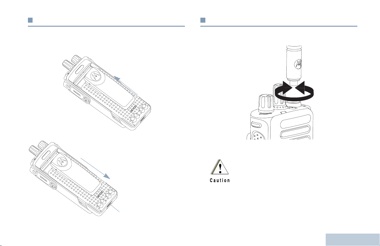
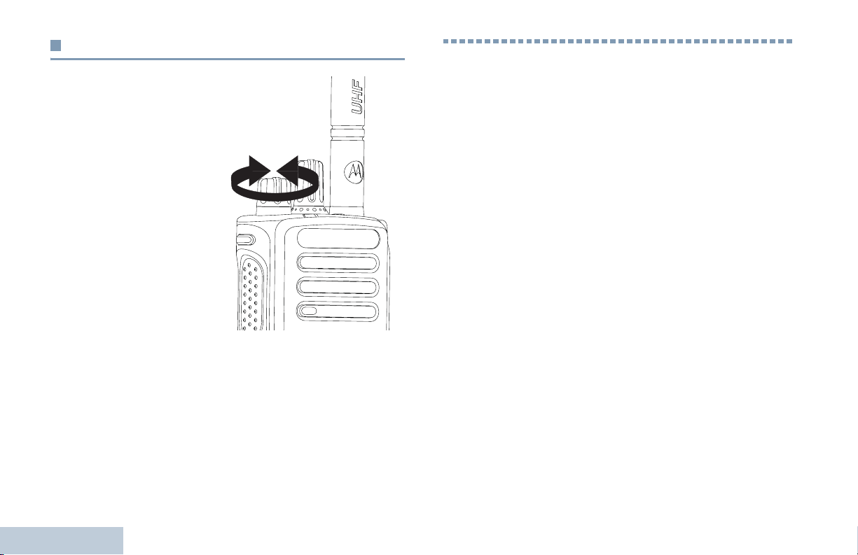
Attaching the Antenna
Align the battery with the rails on the back of the radio. Press
the battery firmly, and slide upward until the latch snaps into
place. Slide battery latch into lock position.
To remove the
battery, turn the
radio off. Move
the battery latch
into unlock
position and
hold, and slide
the battery down
and off the rails.
Battery Latch
With the radio turned off, set the antenna in its receptacle and
turn clockwise.
To remove the antenna, turn the antenna counterclockwise.
If antenna needs to be replaced, ensure that only
MOTOTRBO antennas are used. Neglecting this will
damage your radio. See Antennas on page 98 for a
list of available antennas.
Preparing Your Radio for Use
3
English
Page 16
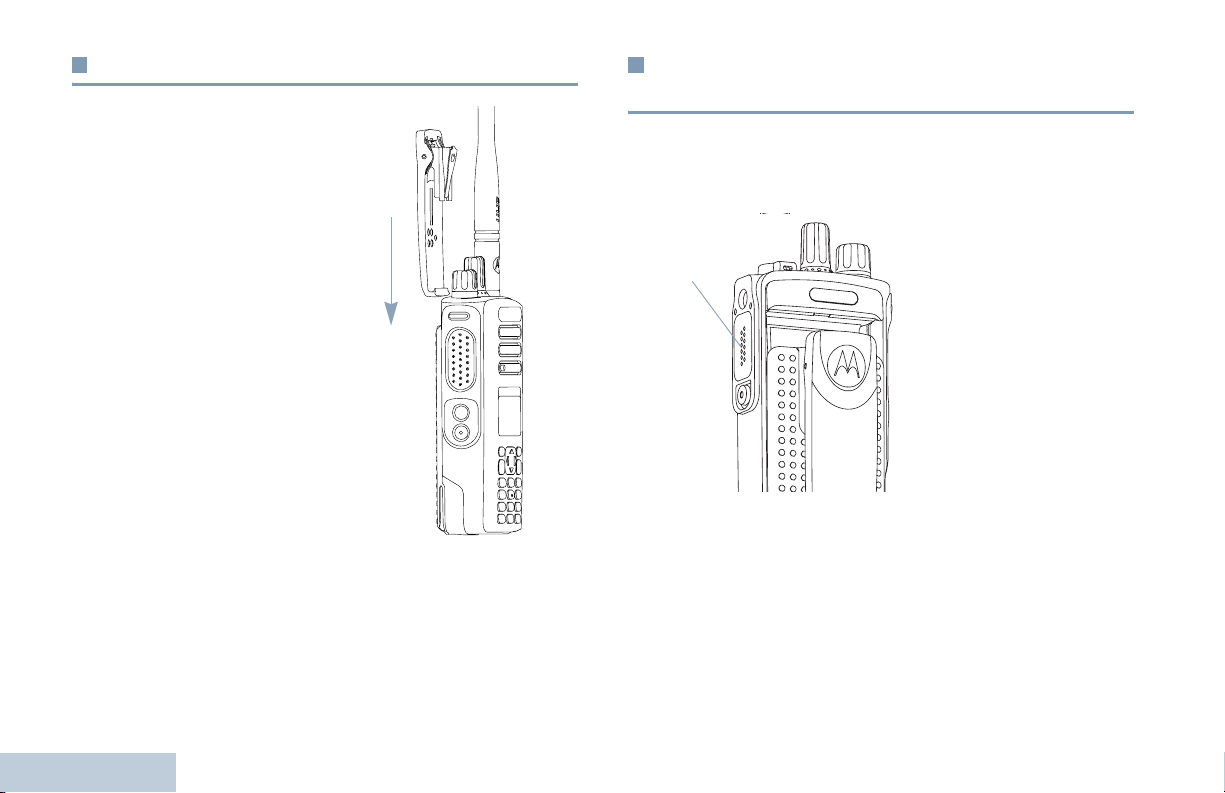
Attaching the Belt Clip
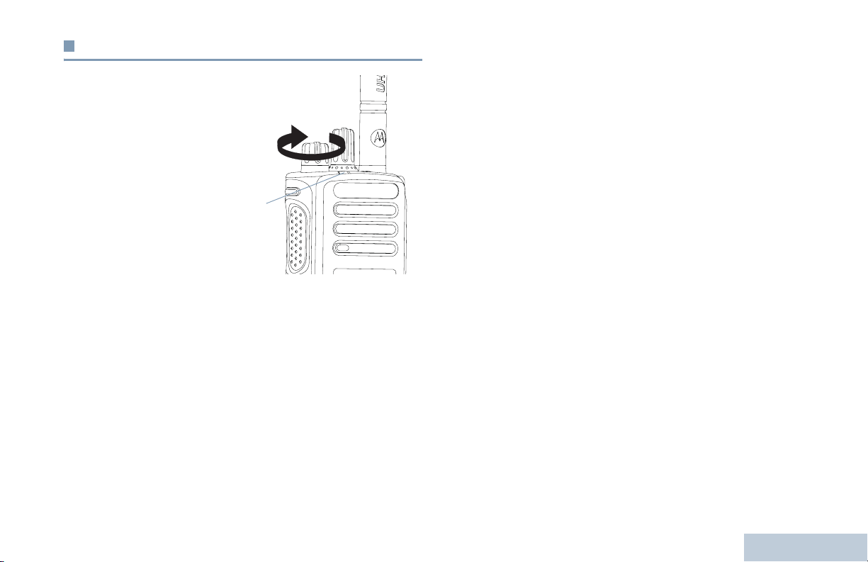
Attaching the Universal Connector Cover
(Dust Cover)
Align the grooves on the clip
with those on the battery and
press downward until you hear
a click.
To remove the clip, press the
belt clip tab away from the
battery. Using a key may be
helpful. Then slide the clip
upward and away from the
radio.
Preparing Your Radio for Use
4
The universal connector is located on the antenna side of the
radio. It is used to connect MOTOTRBO accessories to the
radio.
Insert the hooked end of the
Universal
Connector
connector cover, press down on the cover and turn the
thumbscrew counterclockwise.
Replace the dust cover when the universal connector is not in
use.
cover into the slots above
the universal connector.
Press downward on the
cover to seat the lower tab
properly into the RF
connector.
Turn the thumbscrew
clockwise to secure the
connector cover to the
radio.
To remove the universal
English
Page 17
Powering Up the Radio
Rotate the On/Off/Volume
Control Knob clockwise
until you hear a click. You
see MOTOTRBO (TM) on the
radio’s display momentarily,
followed by a welcome
message or welcome
image.
The LED lights up solid
green and the Home screen
lights up if the backlight
setting is set to turn on
automatically.
LED
NOTE: The Home screen does not light up during a power up if
the LED indicator is disabled (see Turning the LED
Indicator On or Off on page 90).
A brief tone sounds, indicating that the power up test is
successful.
NOTE: There is no power up tone if the radio tones/alerts
function is disabled (see Turning the Radio Tones/
Alerts On or Off on page 84).
If your radio does not power up, check your battery. Make sure
that it is charged and properly attached. If your radio still does
not power up, contact your dealer.
To turn off the radio, rotate this knob counterclockwise until you
hear a click. You see a brief
display.
Powering Down
on the radio’s
Preparing Your Radio for Use
English
5
Page 18
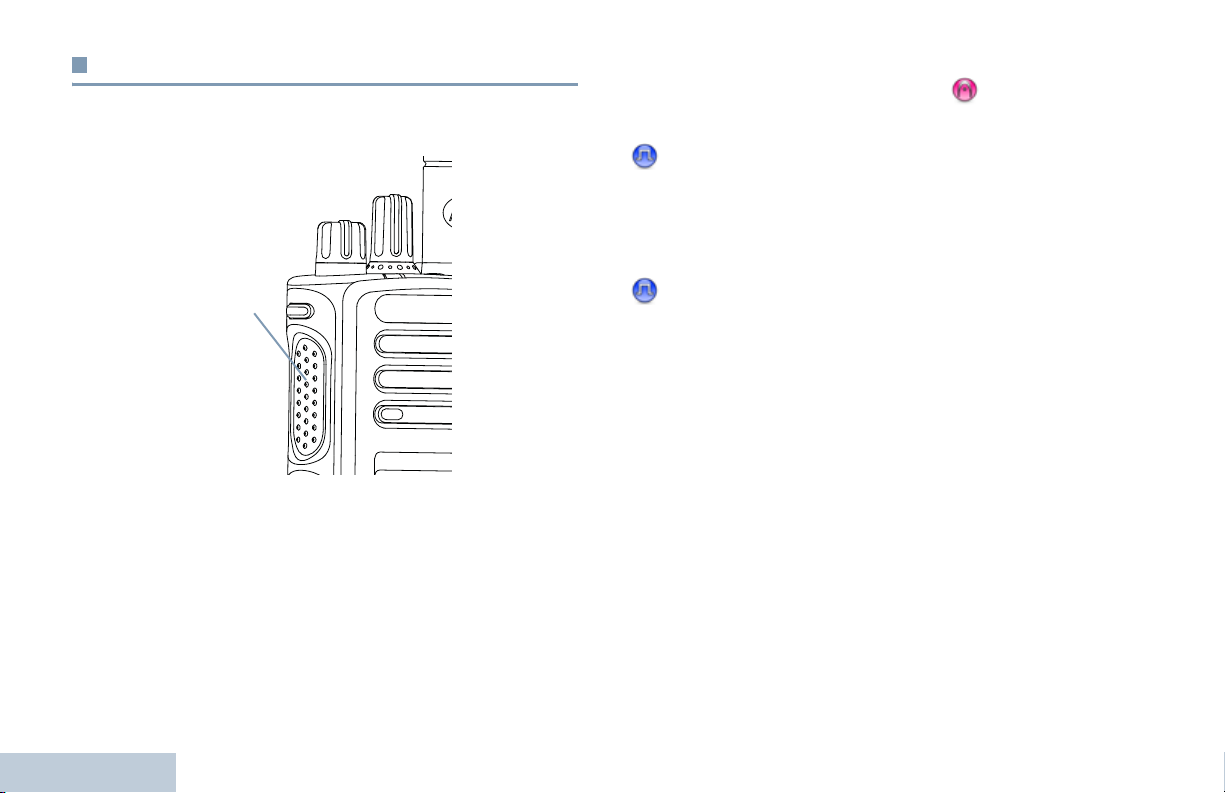
Adjusting the Volume
To increase the volume,
turn the On/Off/Volume
Control Knob clockwise.
To decrease the volume,
turn this knob
counterclockwise.
NOTE: Your radio can be
programmed to
have a minimum
volume offset
where the volume
level cannot be
turned past the
programmed
minimum volume.
Check with your
dealer or system administrator for more information.
Identifying Radio Controls
Identifying Radio Controls
Take a moment to review the following:
Radio Controls . . . . . . . . . . . . . . . . . . . . . . . . . . . . . . . . page 7
Programmable Buttons . . . . . . . . . . . . . . . . . . . . . . . . . page 8
Using the 4-Way Navigation Button. . . . . . . . . . . . . . . page 10
Accessing the Programmed Functions . . . . . . . . . . . . page 10
Using the Keypad . . . . . . . . . . . . . . . . . . . . . . . . . . . . page 11
Push-To-Talk (PTT) Button . . . . . . . . . . . . . . . . . . . . . page 12
Switching Between Conventional Analog and
Digital Mode . . . . . . . . . . . . . . . . . . . . . . . . . . . . . . . page 13
IP Site Connect . . . . . . . . . . . . . . . . . . . . . . . . . . . . . . page 13
Capacity Plus. . . . . . . . . . . . . . . . . . . . . . . . . . . . . . . . page 14
Linked Capacity Plus . . . . . . . . . . . . . . . . . . . . . . . . . . page 14
6
English
Page 19
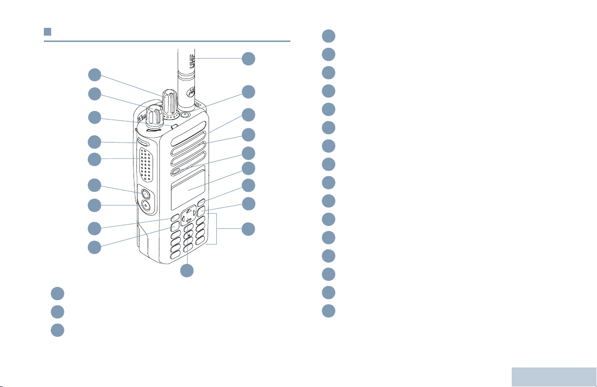
Radio Controls
1
2
3
4
5
6
7
8
9
Channel Selector Knob*
1
On/Off/Volume Control Knob
2
LED Indicator
3
10
19
18
17
16
15
14
13
12
11
Side Button 1**
4
Push-to-Talk (PTT) Button
5
Side Button 2**
6
Side Button 3**
7
Front Button P1**
8
Menu/OK Button
9
4-Way Navigation Button
10
Keypad
11
Back/Home Button
12
Front Button P2**
13
Display
14
Microphone
15
Speaker
16
Universal Connector for Accessories
17
Emergency Button**
18
Antenna
19
* Display radios have a continuous-rotary Channel Selector Knob
** These buttons are programmable.
Identifying Radio Controls
7
English
Page 20

Programmable Buttons
Your dealer can program the programmable buttons as
shortcuts to radio functions or preset channels/groups
depending on the duration of a button press:
• Short press – Pressing and releasing rapidly.
• Long press – Pressing and holding for the programmed
duration.
• Hold down – Keeping the button pressed.
NOTE: The programmed duration of a button press is
applicable for all assignable radio/utility functions or
settings. See Emergency Operation on page 55 for
more information on the programmed duration of the
Emergency button.
Voice Announcement for Channel – Plays zone and channel
announcement voice messages for the current channel. This
function is unavailable when Voice Announcement is disabled.
Emergency – Depending on the programming, initiates or
cancels an emergency alarm or call.
Intelligent Audio On/Off – Toggles Intelligent Audio on or off.
Manual Dial – Initiates a call by keying in any subscriber
ID.
Manual Site Roam*
Mic AGC On/Off – Toggles the internal microphone automatic
gain control (AGC) on or off. Not applicable during a Bluetooth
session.
Monitor – Monitors a selected channel for activity.
‡
– Starts the manual site search.
Assignable Radio Functions
Bluetooth® Audio Switch – Toggles audio routing between
internal radio speaker and external Bluetooth-enabled
accessory.
Contacts – Provides direct access to the contacts list.
Call Alert – Provides direct access to the contacts list for you to
select a contact to whom a Call Alert can be sent.
Identifying Radio Controls
Call Forwarding – Toggles Call Forwarding on or off.
Call Log – Selects the call log list.
8
English
Nuisance Channel Delete*‡ – Temporarily removes an
unwanted channel, except for the Selected Channel, from the
scan list. The Selected Channel refers to the user’s selected
zone/channel combination from which scan is initiated.
One Touch Access – Directly initiates a predefined Private or
Group Call, a Call Alert or a Quick Text message.
Option Board Feature – Toggles option board feature(s) on or
off for option board-enabled channels.
* Not applicable in Capacity Plus
‡
Not applicable in Linked Capacity Plus
Page 21

Permanent Monitor*‡ – Monitors a selected channel for all
radio traffic until function is disabled.
Privacy – Toggles privacy on or off.
Radio Alias and ID – Provides radio alias and ID.
Radio Check – Determines if a radio is active in a system.
Radio Enable – Allows a target radio to be remotely
enabled.
Radio Disable – Allows a target radio to be remotely
disabled.
Remote Monitor – Turns on the microphone of a target
radio without it giving any indicators.
‡
Repeater/Talkaround*
and communicating directly with another radio.
Scan*‡ – Toggles scan on or off.
Site Lock On/Off* – Toggles the automatic site roam on or
off.
Status – Selects the status list menu.
Telemetry Control – Controls the Output Pin on a local or
remote radio.
Text Message – Selects the text message menu.
– Toggles between using a repeater
Transmit Interrupt Remote Dekey – Stops the
transmission of a remote monitored radio without giving any
indicators, or an ongoing interruptible call to free the channel.
Voice Announcement On/Off – Toggles Voice Announcement
on or off.
Voice Operating Transmission (VOX) – Toggles VOX on or
off.
Zone – Allows selection from a list of zones.
* Not applicable in Capacity Plus
‡
Not applicable in Linked Capacity Plus
Assignable Settings or Utility Functions
All Tones/Alerts – Toggles all tones and alerts on or off.
Backlight On/Off – Toggles display backlight on or off.
Backlight Brightness – Adjusts the brightness level.
Display Mode – Toggles the day/night display mode on or off.
Keypad Lock – Toggles keypad between locked and unlocked.
Power Level – Toggles transmit power level between high and
low.
Squelch – Toggles squelch level between tight and
normal.
Identifying Radio Controls
9
English
Page 22

Using the 4-Way Navigation Button
Accessing the Programmed Functions
You can use the 4-way navigation button, e, to scroll through
options, increase/decrease values, and navigate vertically.
Category
Menu Vertical Navigation –
Lists Vertical Navigation –
View Details Vertical Navigation Previous/Next Item
You can use the 4-way navigation button, e, as a number,
alias, or free form text editor.
Editor Category
Number –
Alias –
Free Form Text
Numeric Values Increase/Decrease –
^ or v< or >
^ or v< or >
Left: Delete last digit
Move cursor one
character left/right
Move cursor up/
down
Move cursor one
character left/right
Right: –
Identifying Radio Controls
You can access various radio functions through one of the
following ways:
• A short or long press of the
relevant programmable buttons.
OR
ced
• Use the 4-way navigation button as follows:
1 To access the menu, press the c button. Press the
appropriate direction of the
functions.
e to access the menu
2 To select a function or enter a sub-menu, press the c
button.
3 To go back one menu level, or to return to the previous
screen, press the
return to the Home screen.
NOTE: Your radio automatically exits the menu after a period
of inactivity and returns to your Home screen.
d button. Long press the d button to
10
English
Page 23

Using the Keypad
You can use the 3 x 4 alphanumeric keypad to access your radio’s features. You can use the keypad to enter subscriber aliases or IDs,
and text messages. Many characters require that you press a key multiple times. The table below shows the number of times a key
needs to be pressed to generate the required character.
Number of Times Key is Pressed
Key1 2345678910111213
1
2
3
4
5
6
7
8
9
0
*
#
1.,?!@&‘%-:*#
ABC2
DEF3
GHI4
JKL5
MNO6
PQRS7
TUV8
WXYZ9
0
* or del
# or space
NOTE: Press to enter “0” and long press to activate the CAPS lock. Another long press to turn off the CAPS lock.
NOTE: Press during text entry to delete the character. Press during numeric entry to enter a “*”.
NOTE: Press during text entry to insert a space. Press during numeric entry to enter a “#”.
Identifying Radio Controls
11
English
Page 24
Push-To-Talk (PTT) Button
The PTT button on the side of the radio serves two basic
purposes:
If the Talk Permit Tone (see Turning the Talk Permit Tone On
or Off on page 86) or the PTT Sidetone is enabled, wait
until the short alert tone ends before talking.
During a call, if the Channel Free Indication feature is
enabled on your radio (programmed by your dealer), you
hear a short alert tone the moment the target radio (the
radio that is receiving your call) releases the PTT button,
indicating the channel is free for you to respond.
PTT Button
• While a call is in progress, the PTT button allows the radio to
transmit to other radios in the call.
Press and hold down PTT button to talk. Release the PTT
button to listen.
The microphone is activated when the PTT button is pressed.
Identifying Radio Controls
• While a call is not in progress, the PTT button is used to make
a new call (see Making a Radio Call on page 27).
12
English
You will also hear a continuous talk prohibit tone, if your
call is interrupted, indicating that you should release the
PTT button, for example when the radio receives an
Emergency Call.
Page 25
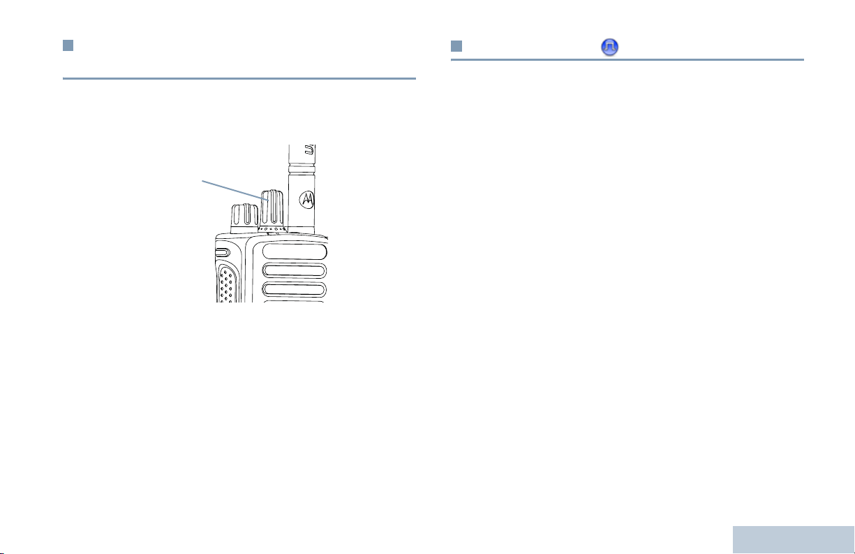
Switching Between Conventional Analog
and Digital Mode
Each channel in your radio can be configured as a conventional
analog or conventional digital channel. Use the Channel
Selector Knob to switch between an analog or a digital channel.
Channel
Selector
Knob
When switching from digital to analog mode, certain features
are unavailable. Icons for the digital features (such as
Messages) reflect this change by appearing ‘grayed out’.
Disabled features are hidden in the menu.
Your radio also has features available in both analog and digital
mode. However, the minor differences in the way each feature
works does NOT affect the performance of your radio.
NOTE: Your radio also switches between digital and analog
modes during a dual mode scan (see Scan on
page 41).
IP Site Connect
This feature allows your radio to extend conventional
communication beyond the reach of a single site, by connecting
to different available sites which are connected via an Internet
Protocol (IP) network.
When the radio moves out of range from one site and into the
range of another, it connects to the new site's repeater to send
or receive calls/data transmissions. Depending on your settings,
this is done automatically or manually.
If the radio is set to do this automatically, it scans through all
available sites when the signal from the current site is weak or
when the radio is unable to detect any signal from the current
site. It then locks on to the repeater with the strongest Received
Signal Strength Indicator (RSSI) value.
In a manual site search, the radio searches for the next site in
the roam list that is currently in range (but which may not have
the strongest signal) and locks on to it.
NOTE: Each channel can only have either Scan or Roam
enabled, not both at the same time.
Channels with this feature enabled can be added to a particular
roam list. The radio searches the channel(s) in the roam list
during the automatic roam operation to locate the best site.
A roam list supports a maximum of 16 channels (including the
Selected Channel).
Identifying Radio Controls
13
English
Page 26

NOTE: You cannot manually add or delete an entry to the roam
list. Check with your dealer or system administrator for
more information.
Capacity Plus
Capacity Plus is a single-site trunking configuration of the
MOTOTRBO radio system, which uses a pool of channels to
support hundreds of users and up to 254 Groups. This feature
allows your radio to efficiently utilize the available number of
programmed channels while in Repeater Mode.
Icons of features not applicable to Capacity Plus are not
available in the menu. You hear a negative indicator tone if you
try to access a feature not applicable to Capacity Plus via a
programmable button press.
Your radio also has features that are available in conventional
digital mode, IP Site Connect, Capacity Plus and Linked
Capacity Plus. However, the minor differences in the way each
feature works does NOT affect the performance of your radio.
Check with your dealer or system administrator for more
information on this configuration.
Identifying Radio Controls
14
Linked Capacity Plus
Linked Capacity Plus is a multi-site multi-channel trunking
configuration of the MOTOTRBO radio system, combining the
best of both Capacity Plus and IP Site Connect configurations.
Linked Capacity Plus allows your radio to extend trunking
communication beyond the reach of a single site, by connecting
to different available sites which are connected via an Internet
Protocol (IP) network. It also provides an increase in capacity by
efficiently utilizing the combined available number of
programmed channels supported by each of the available sites.
When the radio moves out of range from one site and into the
range of another, it connects to the new site's repeater to send
or receive calls/data transmissions. Depending on your settings,
this is done automatically or manually.
If the radio is set to do this automatically, it scans through all
available sites when the signal from the current site is weak or
when the radio is unable to detect any signal from the current
site. It then locks on to the repeater with the strongest Received
Signal Strength Indicator (RSSI) value.
In a manual site search, the radio searches for the next site in
the roam list that is currently in range (but which may not have
the strongest signal) and locks on to it.
Any channel with Linked Capacity Plus enabled can be added
to a particular roam list. The radio searches these channels
during the automatic roam operation to locate the best site.
English
Page 27

NOTE: You cannot manually add or delete an entry to the
roam list. Check with your dealer or system
administrator for more information.
Similar to Capacity Plus, icons of features not applicable to
Linked Capacity Plus are not available in the menu. You hear a
negative indicator tone if you try to access a feature not
applicable to Linked Capacity Plus via a programmable button
press.
Check with your dealer or system administrator for more
information on this configuration.
Identifying Status Indicators
Identifying Status Indicators
Your radio indicates its operational status through the following:
Display Icons . . . . . . . . . . . . . . . . . . . . . . . . . . . . . . . . page 16
Call Icons . . . . . . . . . . . . . . . . . . . . . . . . . . . . . . . . . . .page 17
Advanced Menu Icons . . . . . . . . . . . . . . . . . . . . . . . . .page 18
Mini Notice Icons . . . . . . . . . . . . . . . . . . . . . . . . . . . . .page 18
Sent Item Icons . . . . . . . . . . . . . . . . . . . . . . . . . . . . . .page 19
Bluetooth Device Icons . . . . . . . . . . . . . . . . . . . . . . . .page 19
LED Indicator . . . . . . . . . . . . . . . . . . . . . . . . . . . . . . . . page 20
Audio Tones . . . . . . . . . . . . . . . . . . . . . . . . . . . . . . . . .page 21
Indicator Tones . . . . . . . . . . . . . . . . . . . . . . . . . . . . . . . page 21
English
15
Page 28
Display Icons
The 132 x 90 pixels, 256 colors, liquid crystal display (LCD) of
your radio shows radio status, text entries, and menu entries.
The following are icons that appear on the status bar at the top
of the radio’s display. Icons are displayed on the status bar,
arranged left-to-right, in order of appearance/usage and are
channel specific.
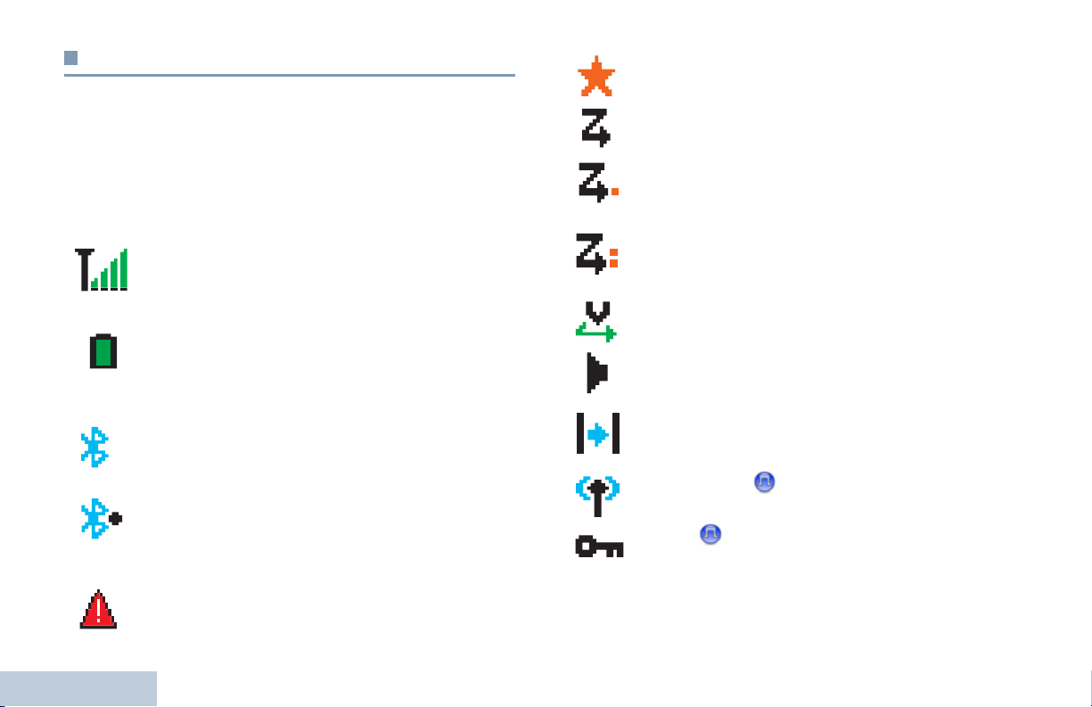
Received Signal Strength Indicator (RSSI)
The number of bars displayed represents the radio
signal strength. Four bars indicate the strongest
signal. This icon is only displayed while receiving.
Battery
The number of bars (0 – 4) shown indicates the
charge remaining in the battery.
Blinks when the battery is low.
Bluetooth
The Bluetooth feature is enabled but there is no
remote Bluetooth device connected.
Bluetooth Connected
The Bluetooth feature is enabled. The icon stays lit
when one or more remote Bluetooth devices are
Identifying Status Indicators
connected.
Emergency
Radio is in Emergency mode.
16
Notification
Notification List has one or more missed events.
‡
*
Scan
Scan feature is enabled.
Scan – Priority 1*
‡
Radio detects activity on channel/group designated
as Priority 1).
Scan – Priority 2*
‡
Radio detects activity on channel/group designated
as Priority 2.
Vot e S c a n
Vote scan feature is enabled.
Monitor
Selected channel is being monitored.
‡
Talkaround
*
In the absence of a repeater, radio is currently
configured for direct radio to radio communication.
Site Roaming*
The site roaming feature is enabled.
Secure
The Privacy feature is enabled.
* Not applicable in Capacity Plus
‡
Not applicable in Linked Capacity Plus
English
Page 29
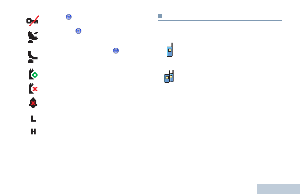
Unsecure
The Privacy feature is disabled.
GPS Available
The GPS feature is enabled. The icon stays lit when
a position fix is available.
GPS Not Available/Out of Range
The GPS feature is enabled but is not receiving data
from the satellite.
Option Board
The Option Board is enabled.
Option Board Non-Function
The Option Board is disabled.
Tones Disable
Tones are turned off.
Power Level
Radio is set at Low power.
OR
Radio is set at High power.
* Not applicable in Capacity Plus
‡
Not applicable in Linked Capacity Plus
Call Icons
The following icons appear on the radio’s display during a call.
These icons also appear in the Contacts list to indicate ID type.
Private Call
Indicates a Private Call in progress.
In the Contacts list, it indicates a subscriber alias
(name) or ID (number).
Group Call/All Call
Indicates a Group Call or All Call in progress.
In the Contacts list, it indicates a group alias (name)
or ID (number).
Identifying Status Indicators
English
17
Page 30
Advanced Menu Icons
Mini Notice Icons
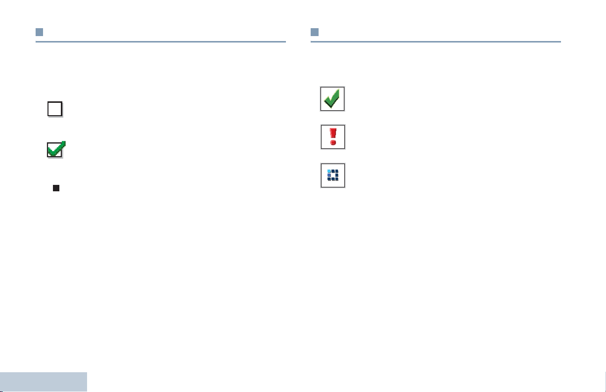
The following icons appear beside menu items that offer a
choice between two options or as an indication that there is a
sub-menu offering two options.
Checkbox (Empty)
Indicates the option is not selected.
Checkbox (Checked)
Indicates the option is selected.
Solid Black Box
Indicates the option selected for the menu item with a
sub-menu.
Identifying Status Indicators
The following icons appear momentarily on the radio’s display
after an action to perform task is taken.
Successful Transmission (Positive)
Successful action taken.
Failed Transmission (Negative)
Failed action taken.
Transmission in Progress (Transitional)
Transmitting. This dynamic icon is seen before
indication for Successful Transmission or Failed
Transmission.
18
English
Page 31

Sent Item Icons
Bluetooth Device Icons
The following icons appear in the Sent Items folder.
Sent Successfully
OR
The text message is sent successfully.
Send Failed
OR
The text message cannot be sent.
In-Progress
• The text message to a subscriber alias or ID is
OR
pending transmission, followed by waiting for
acknowledgement.
• The text message to a group alias or ID is pending
transmission.
The following icons also appear next to items in the list of
Bluetooth-enabled devices available to indicate the device type.
Bluetooth Data Device
Bluetooth-enabled data device, such as a scanner.
Bluetooth Audio Device
Bluetooth-enabled audio device, such as a headset.
Bluetooth PTT Device
Bluetooth-enabled PTT device, such as a PTT-Only
Device (POD).
Identifying Status Indicators
English
19
Page 32
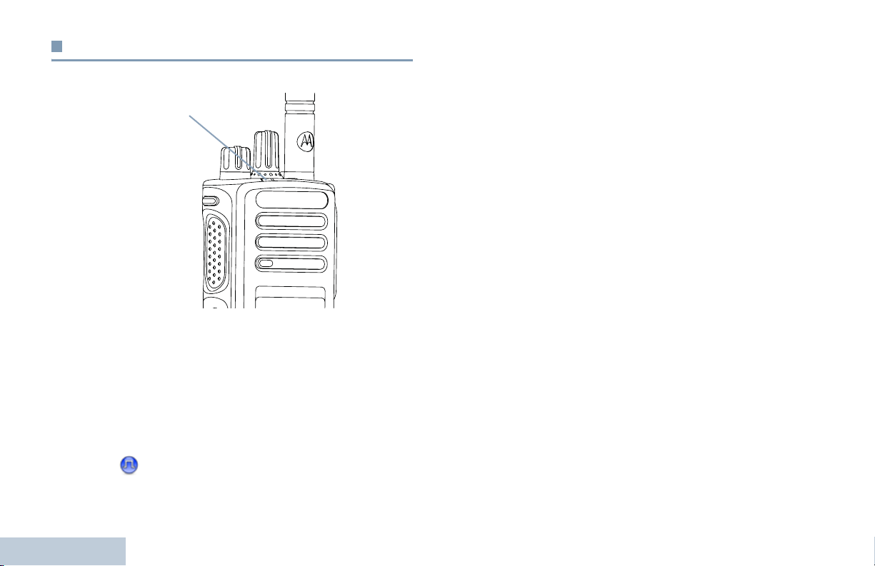
LED Indicator
The LED indicator shows the operational status of your radio.
LED Indicator
Blinking red – Radio is transmitting at low battery condition,
receiving an emergency transmission or has failed the self-test
upon powering up.
Solid green – Radio is powering up, or transmitting.
Blinking green – Radio is receiving a non-privacy-enabled call
or data, or detecting activity over the air.
Double blinking green – Radio is receiving a privacy-enabled
Identifying Status Indicators
call or data .
Blinking yellow – Radio is scanning for activity or receiving a
Call Alert, or all local Linked Capacity Plus channels are busy.
Double blinking yellow – Radio is no longer connected to the
repeater while in Capacity Plus or Linked Capacity Plus, all
Capacity Plus channels or Linked Capacity Plus channels are
currently busy, Auto Roaming is enabled, radio is actively
searching for a new site. Also indicates radio has yet to respond
to a group call alert, or radio is locked.
NOTE: While in conventional mode, when the LED blinks
green, it indicates the radio detects activity over the air.
Due to the nature of the digital protocol, this activity
may or may not affect the radio's programmed channel.
For Capacity Plus and Linked Capacity Plus, there is
no LED indication when the radio is detecting activity
over the air.
Solid yellow – Radio is monitoring a conventional channel.
20
English
Page 33

Indicator Tones
Audio Tones
High pitched tone Low pitched tone
Positive Indicator Tone
Negative Indicator Tone
Alert tones provide you with audible indications of the radio’s
status or the radio’s response to data received.
Continuous Tone A monotone sound. Sounds
continuously until termination.
Periodic Tone Sounds periodically depending on the
duration set by the radio. Tone starts,
stops, and repeats itself.
Repetitive Tone A single tone that repeats itself until it is
terminated by the user.
Momentary Tone Sounds only once for a short period of
time defined by the radio.
Identifying Status Indicators
English
21
Page 34

Making and Receiving Calls
Once you understand how your MOTOTRBO Portable is
configured, you are ready to use your radio.
Use this navigation guide to familiarize yourself with the basic
Call features:
Selecting a Zone . . . . . . . . . . . . . . . . . . . . . . . . . . . . . page 22
Selecting a Radio Channel, Subscriber ID,
or Group ID . . . . . . . . . . . . . . . . . . . . . . . . . . . . . . . page 24
Receiving and Responding to a Radio Call. . . . . . . . . page 24
Making a Radio Call . . . . . . . . . . . . . . . . . . . . . . . . . . page 27
Stopping a Radio Call . . . . . . . . . . . . . . . . . . . . . . . . . page 31
Talkaround . . . . . . . . . . . . . . . . . . . . . . . . . . . . . . . . . page 32
Monitoring Features . . . . . . . . . . . . . . . . . . . . . . . . . . page 33
Making and Receiving Calls
22
Selecting a Zone
A zone is a group of channels. Your radio supports up to 1000
channels and 250 zones, with a maximum of 160 channels per
zone.
Use the following procedure to select a zone.
Procedure:
Press the programmed Zone button and proceed to Step 3.
OR
Follow the procedure below.
1 c to access the menu.
2 ^ or v to Zone and press c to select.
3 The current zone is displayed and indicated by a 9.
4 ^ or v to the required zone and proceed to Step 7.
OR
Key in the first character of the required zone.
5 A blinking cursor appears.
Use the keypad to type the required zone.
Press
< to move one space to the left.
> to move one space to the right.
Press
Press the *DEL key to delete any unwanted characters.
6 The first line of the display shows the characters you keyed
in. The next lines of the display show the shortlisted search
English
Page 35

results.
The alias search is case-insensitive. If there are two or more
zones with the same name, the radio displays the zone that
is listed first in the zone list.
7 Press c to select.
8 The display shows <Zone> Selected momentarily and
returns to the selected zone screen.
Selecting a Channel
Transmissions are sent and received on a channel. Depending
on your radio's configuration, each channel may have been
programmed differently to support different groups of users or
supplied with different features. After selecting the required
zone, select the channel you require to transmit or receive on.
Procedure:
Turn the Channel Selector Knob to select the channel with the
active group alias or ID.
Making and Receiving Calls
English
23
Page 36

Receiving and Responding to a Radio Call
Once the channel, subscriber
ID or group ID is displayed,
you can proceed to receive
and respond to calls.
The LED lights up solid green
while the radio is transmitting
and blinks green when the
radio is receiving.
NOTE: The LED lights up solid green while the radio is
transmitting and double blinks green when the radio is
receiving a privacy-enabled call.
To unscramble a privacy-enabled call, your radio must
have the same Privacy Key, OR the same Key Value
and Key ID (programmed by your dealer), as the
transmitting radio (the radio you are receiving the call
from).
See Privacy on page 72 for more information.
LED Indicator
Making and Receiving Calls
Receiving and Responding to a Group Call
To receive a call made to a group of users, your radio must be
configured as part of that group.
Procedure:
When you receive a Group Call (while on the Home screen):
1 The LED blinks green.
2 The Group Call icon appears in the top right corner. The first
text line shows the caller alias. The second text line displays
the group call alias. Your radio unmutes and the incoming
call sounds through the radio's speaker.
3 To respond, hold the radio vertically 1 to 2 inches (2.5 to 5.0
cm) from your mouth.
4 If the Channel Free Indication feature is enabled, you
hear a short alert tone the moment the transmitting radio
releases the PTT button, indicating the channel is free for
you to respond.
Press the PTT button to respond to the call.
OR
If the Voice Interrupt feature is enabled, press the PTT
button to stop the current call from the transmitting radio and
free the channel for you to talk/respond.
24
English
Page 37

5 The LED lights up solid green.
6 Wait for the Talk Permit Tone to finish (if enabled) and speak
clearly into the microphone.
OR
Wait for the PTT Sidetone to finish (if enabled) and
speak clearly into the microphone.
7 Release the PTT button to listen.
8 If there is no voice activity for a predetermined period of
time, the call ends.
See Making a Group Call on page 27 for details on making a
Group Call.
Receiving and Responding to a Private Call
A Private Call is a call from an individual radio to another
individual radio.
Procedure:
When you receive a Private Call:
1 The LED blinks green.
2 The Private Call icon appears in the top right corner. The
first text line shows the caller alias. Your radio unmutes and
the incoming call sounds through the radio's speaker.
3 To respond, hold the radio vertically 1 to 2 inches (2.5 to 5.0
cm) from your mouth.
4 If the Channel Free Indication feature is enabled, you hear a
short alert tone the moment the transmitting radio releases
the PTT button, indicating the channel is free for you to
respond.
Press the PTT button to respond to the call.
OR
If the Voice Interrupt feature is enabled, press the PTT
button to stop the current call from the transmitting radio and
free the channel for you to talk/respond.
5 The LED lights up solid green.
6 Wait for the Talk Permit Tone to finish (if enabled) and
speak clearly into the microphone.
7 Release the PTT button to listen.
8 If there is no voice activity for a predetermined period of
time, the call ends.
9 You hear a short tone. The display shows Call Ended.
See Making a Private Call on page 28 for details on making a
Private Call.
Receiving an All Call
An All Call is a call from an individual radio to every radio on the
channel. It is used to make important announcements requiring
the user’s full attention.
Making and Receiving Calls
25
English
Page 38

Procedure:
When you receive an All Call:
1 A tone sounds and the LED blinks green.
Procedure:
When you receive a Selective Call:
1 The LED blinks green.
2 The Group Call icon appears in the top right corner. The first
text line shows the caller alias. The second text line displays
All Call. Your radio unmutes and the incoming call
sounds through the radio's speaker.
3 Once the All Call ends, the radio returns to the previous
screen before receiving the call. An All Call does not wait for
a predetermined period of time before ending.
If the Channel Free Indication feature is enabled, you
hear a short alert tone the moment the transmitting radio
releases the PTT button, indicating the channel is now
available for use.
You cannot respond to an All Call.
See Making an All Call on page 29 for details on making an All
Call.
NOTE: The radio stops receiving the All Call if you switch to a
different channel while receiving the call.
During an All Call, you are not able to use any
programmed button functions until the call ends.
Making and Receiving Calls
Receiving and Responding to a Selective Call
A Selective Call is a call from an individual radio to another
individual radio. It is a Private Call on an analog system.
26
2 The Private Call icon appears in the top right corner. The
first text line shows the caller alias or Selective Call or
Alert with Call. Your radio unmutes and the incoming
call sounds through the radio's speaker.
3 To respond, hold the radio vertically 1 to 2 inches (2.5 to 5.0
cm) from your mouth.
4 If the Channel Free Indication feature is enabled, you hear a
short alert tone the moment the transmitting radio releases
the PTT button, indicating the channel is free for you to
respond.
Press the PTT button to respond to the call.
5 The LED lights up solid green.
6 Wait for the Talk Permit Tone to finish (if enabled) and
speak clearly into the microphone.
7 Release the PTT button to listen.
8 If there is no voice activity for a predetermined period of
time, the call ends.
9 You hear a short tone. The display shows Call Ended.
NOTE: See Making a Selective Call on page 29 for details on
making a Private Call.
English
Page 39

Making a Radio Call
After selecting your channel, you can select a subscriber alias
or ID, or group alias or ID by using:
• The Channel Selector Knob
• A programmed One Touch Access button
• The programmed number keys – This method is for Group,
Private and All Calls only and is used with the keypad (see
Making a Group, Private or All Call with the
Programmable Number Key on page 30).
• The Contacts list (see Contacts Settings on page 44)
• Manual Dial (via Contacts) – This method is for Private Calls
only and is dialed using the keypad (see Making a Private
Call from Contacts on page 45.
NOTE: Your radio must have the Privacy feature enabled on
the channel to send a privacy-enabled transmission.
Only target radios with the same Privacy Key OR the
same Key Value and Key ID as your radio are able to
unscramble the transmission.
See Privacy on page 72 for more information.
The One Touch Access feature allows you to make a
Group or Private Call to a predefined ID easily. This
feature can be assigned to a short or long
programmable button press.You can ONLY have one
ID assigned to a One Touch Access button. Your
radio can have multiple One Touch Access buttons
programmed.
Making a Call with the Channel Selector Knob
Making a Group Call
To make a call to a group of users, your radio must be
configured as part of that group.
Procedure:
1 Select the channel with the active group alias or ID. See
Selecting a Channel on page 23.
OR
Press the programmed One Touch Access button.
2 Hold the radio vertically 1 to 2 inches (2.5 to 5.0 cm) from
your mouth.
3 Press the PTT button to make the call. The LED lights up
solid green. The Group Call icon appears in the top right
corner. The first text line shows the group call alias.
4 Wait for the Talk Permit Tone to finish (if enabled) and
speak clearly into the microphone.
OR
Wait for the PTT Sidetone to finish (if enabled) and
speak clearly into the microphone.
Making and Receiving Calls
27
English
Page 40

5 Release the PTT button to listen.When the target radio
responds, the LED blinks green. You see the Group Call
icon, the group alias or ID, and transmitting radio alias or ID
on your display.
6 If the Channel Free Indication feature is enabled, you
hear a short alert tone the moment the target radio releases
the PTT button, indicating the channel is free for you to
respond. Press the PTT button to respond.
OR
If there is no voice activity for a predetermined period of
time, the call ends.
7 Radio returns to the screen you were on prior to initiating the
call.
You can also make a Group Call via Contacts (see Making a
Group Call from Contacts on page 44).
Making a Private Call
While you can receive and/or respond to a Private Call
initiated by an authorized individual radio, your radio
must be programmed for you to initiate a Private Call.
There are two types of Private Calls. The first type, where a
radio presence check is performed prior to setting up the call,
while the other sets up the call immediately.
Making and Receiving Calls
Only one of these call types can be programmed to your
radio by your dealer.
28
You hear a negative indicator tone, when you make a Private
Call via the Contacts list, Call Log, One Touch Access button,
the programmed number keys, or the Channel Selector Knob,
if this feature is not enabled.
Use the Text Message or Call Alert features to contact an
individual radio. See Text Message Features on page 60 or
Call Alert Operation on page 53 for more information.
Procedure:
1 Select the channel with the active group alias or ID. See
Selecting a Channel on page 23.
OR
Press the programmed One Touch Access button.
2 Hold the radio vertically 1 to 2 inches (2.5 to 5.0 cm) from
your mouth.
3 Press the PTT button to make the call. The LED lights up
solid green. The Private Call icon appears in the top right
corner. The first text line shows the subscriber alias. The
second text line displays the call status.
4 Wait for the Talk Permit Tone to finish (if enabled) and
speak clearly into the microphone.
5 Release the PTT button to listen. When the target radio
responds, the LED blinks green.
6 If the Channel Free Indication feature is enabled, you hear a
short alert tone the moment the target radio releases the
PTT button, indicating the channel is free for you to respond.
English
Page 41

Press the PTT button to respond.
OR
If there is no voice activity for a predetermined period of
time, the call ends.
7 You hear a short tone. The display shows Call Ended.
You can also make a Private Call via Contacts (see Making a
Private Call from Contacts on page 45) or perform a quick
alphanumeric search for the required alias via a keypad entry
(see Making a Call by Alias Search on page 46).
NOTE: If you release the PTT button while the radio is setting
up the call, it exits without any indication and returns to
the previous screen.
Your radio may be programmed to perform a radio
presence check prior to setting up the Private Call. If
the target radio is not available, you hear a short tone
and see negative mini notice on the display.
Procedure:
1 Select the channel with the active group alias or ID. See
Selecting a Channel on page 23.
2 Hold the radio vertically 1 to 2 inches (2.5 to 5.0 cm) from
your mouth.
3 Press the PTT button to make the call. The LED lights up
solid green. The Group Call icon appears in the top right
corner. The first text line shows All Call.
4 Wait for the Talk Permit Tone to finish (if enabled) and
speak clearly into the microphone.
OR
Wait for the PTT Sidetone to finish (if enabled) and
speak clearly into the microphone.
Users on the channel cannot respond to an All Call.
Making a Selective Call
Making and Receiving Calls
The radio returns to the menu prior to initiating the
radio presence check.
Making an All Call
This feature allows you to transmit to all users on the channel.
Your radio must be programmed to allow you to use this
feature.
Just like a Private Call, while you can receive and/or
respond to a Selective Call initiated by an authorized
individual radio, your radio must be programmed for you
to initiate a Selective Call.
Procedure:
1 Select the channel with the active group alias or ID. See
Selecting a Channel on page 23.
29
English
Page 42

2 Hold the radio vertically 1 to 2 inches (2.5 to 5.0 cm) from
your mouth.
3 Press the PTT button to make the call. The LED lights up
solid green. The Private Call icon appears in the top right
corner. The first text line shows the subscriber alias. The
second text line displays the call status.
4 Wait for the Talk Permit Tone to finish (if enabled) and
speak clearly into the microphone.
OR
Wait for the PTT Sidetone to finish (if enabled) and speak
clearly into the microphone.
5 Release the PTT button to listen. When the target radio
responds, the LED blinks green.
6 If the Channel Free Indication feature is enabled, you hear a
short alert tone the moment the target radio releases the
PTT button, indicating the channel is free for you to respond.
Press the PTT button to respond.
OR
If there is no voice activity for a predetermined period of
time, the call ends.
7 You hear a short tone. The display shows Call Ended.
Making and Receiving Calls
Making a Group, Private or All Call with the
Programmable Number Key
The Programmable Number Key feature allows you to make a
Group, Private or All Call to a predefined alias or ID easily. This
feature can be assigned to all the available number keys on a
keypad.
You can ONLY have one alias or ID assigned to a number key,
but you can have more than one number key associated to an
alias or ID.
Procedure:
When you are on the Home screen:
1 Long press the programmed number key to make a Group,
Private or All Call to the predefined alias or ID.
If the number key is not associated to an entry, a negative
indicator tone sounds.
2 Hold the radio vertically 1 to 2 inches (2.5 to 5.0 cm) from
your mouth.
3 Press the PTT button to make the call. The LED lights up
solid green. The Group/Private Call icon appears in the top
right corner. The first text line shows the caller alias. The
second text line displays either the call status for a Private
Call or All Call for All Call.
30
English
Page 43

4 Wait for the Talk Permit Tone to finish (if enabled) and speak
clearly into the microphone.
OR
For Group Call only: Wait for the PTT Sidetone to
finish (if enabled) and speak clearly into the microphone.
5 Release the PTT button to listen. When the target radio
responds, the LED blinks green.
6 If the Channel Free Indication feature is enabled, you hear a
short alert tone the moment the target radio releases the
PTT button, indicating the channel is free for you to respond.
Press the PTT button to respond.
OR
If there is no voice activity for a predetermined period of
time, the call ends.
7 Radio returns to the screen you were on prior to initiating the
call.
For a Private Call, you hear a short tone when the call ends.
See Assigning an Entry to a Programmable Number Key on
page 47 for details on assigning an entry to a number key on
the keypad.
Stopping a Radio Call
This feature allows you to stop an ongoing Group or Private Call
to free the channel for transmission. For example, when a radio
experiences a “stuck microphone” condition where the PTT
button is inadvertently pressed by the user.
Your radio must be programmed to allow you to use this feature.
Procedure:
While on the required channel:
1 Press the programmed Transmit Interrupt Remote Dekey
button.
2 The display shows Remote Dekey.
3 Wait for acknowledgment.
4 The radio sounds a positive indicator tone and the display
shows Remote Dekey Success, indicating that the channel
is now free.
OR
The radio sounds a negative indicator tone and the display
shows Remote Dekey Failed.
On the interrupted radio, the display shows
and your radio sounds a negative indicator tone until you
release the PTT button, if it is transmitting an interruptible call
that is stopped via this feature.
Call Interrupted
Making and Receiving Calls
English
31
Page 44

Talkaround
You can continue to communicate when your repeater is not
operating, or when your radio is out of the repeater’s range but
within talking range of other radios.
This is called “talkaround”.
5 Press c to enable Talkaround. The display shows 9
beside Enabled.
OR
Press
c to disable Talkaround. The 9 disappears from
beside Enabled.
6 The screen automatically returns to the previous menu.
NOTE: This feature is not applicable in Capacity Plus and
Linked Capacity Plus.
Procedure:
Press the programmed Repeater/Talkaround button to toggle
between talkaround and repeater modes.
OR
Follow the procedure below.
1 c to access the menu.
2 ^ or v to Utilities and press c to select.
3 ^ or v to Radio Settings and press c to select.
4 ^ or v to Talkaround.
Making and Receiving Calls
32
English
The Talkaround setting is retained even after powering down.
NOTE: At Step 4, you can also use
selected option.
< or > to change the
Page 45

Monitoring Features
Monitoring a Channel
Use the Monitor feature to make sure a channel is clear before
transmitting.
NOTE: This feature is not applicable in Capacity Plus and
Linked Capacity Plus.
Procedure:
1 Press and hold the programmed Monitor button and listen
for activity.
2 The monitor icon appears on the status bar and the LED
lights up solid yellow.
3 You hear radio activity or total silence, depending on how
your radio is programmed.
4 When you hear “white noise” (that is, the channel is free),
press the PTT button to talk and release it to listen.
Permanent Monitor
Use the Permanent Monitor feature to continuously monitor a
selected channel for activity.
NOTE: This feature is not applicable in Capacity Plus and
Linked Capacity Plus.
Procedure:
1 Press the programmed Permanent Monitor button.
2 Radio sounds an alert tone, the LED lights up solid yellow,
and the display shows Permanent Monitor On. The
monitor icon appears on the status bar.
3 Press the programmed Permanent Monitor button to exit
Permanent Monitor mode.
4 Radio sounds an alert tone, the LED turns off, and display
shows Permanent Monitor Off.
Making and Receiving Calls
English
33
Page 46

Advanced Features
Use this navigation guide to learn more about advanced
features available with your radio:
Radio Check . . . . . . . . . . . . . . . . . . . . . . . . . . . . . . . . page 35
Remote Monitor. . . . . . . . . . . . . . . . . . . . . . . . . . . . . . page 36
Scan Lists . . . . . . . . . . . . . . . . . . . . . . . . . . . . . . . . . . page 38
Scan . . . . . . . . . . . . . . . . . . . . . . . . . . . . . . . . . . . . . . page 41
Vote Scan . . . . . . . . . . . . . . . . . . . . . . . . . . . . . . . . . . page 43
Contacts Settings . . . . . . . . . . . . . . . . . . . . . . . . . . . . page 44
Call Indicator Settings . . . . . . . . . . . . . . . . . . . . . . . . . page 48
Call Log Features . . . . . . . . . . . . . . . . . . . . . . . . . . . . page 52
Call Alert Operation. . . . . . . . . . . . . . . . . . . . . . . . . . . page 53
Emergency Operation . . . . . . . . . . . . . . . . . . . . . . . . . page 55
Text Message Features. . . . . . . . . . . . . . . . . . . . . . . . page 60
Analog Message Encode . . . . . . . . . . . . . . . . . . . . . . page 71
Analog Status Update . . . . . . . . . . . . . . . . . . . . . . . . . page 71
Privacy . . . . . . . . . . . . . . . . . . . . . . . . . . . . . . . . . . . . page 72
Dual Tone Multi Frequency (DTMF) . . . . . . . . . . . . . . page 73
Multi-Site Controls. . . . . . . . . . . . . . . . . . . . . . . . . . . . page 74
Security . . . . . . . . . . . . . . . . . . . . . . . . . . . . . . . . . . . . page 76
Lone Worker . . . . . . . . . . . . . . . . . . . . . . . . . . . . . . . . page 78
Advanced Features
Password Lock Features. . . . . . . . . . . . . . . . . . . . . . . page 78
Bluetooth Operation . . . . . . . . . . . . . . . . . . . . . . . . . . page 81
Notification List . . . . . . . . . . . . . . . . . . . . . . . . . . . . . . page 84
34
Utilities . . . . . . . . . . . . . . . . . . . . . . . . . . . . . . . . . . . . . page 84
Front Panel Configuration (FPC) . . . . . . . . . . . . . . . . . page 97
English
Page 47

Radio Check
If enabled, this feature allows you to determine if another radio
is active in a system without disturbing the user of that radio. No
audible or visual notification is shown on the target radio.
This feature is only applicable for subscriber aliases or IDs.
5 If successful, a positive indicator tone sounds and the
display shows positive mini notice.
OR
If unsuccessful, a negative indicator tone sounds and the
display shows negative mini notice.
6 Radio returns to the subscriber alias or ID screen.
Advanced Features
Sending a Radio Check
Procedure:
Use the programmed Radio Check button.
1 Press the programmed Radio Check button.
2 ^ or v to the required subscriber alias or ID and press c
to select.
3 The display shows transitional mini notice, indicating the
request is in progress. The LED lights up solid green.
4 Wait for acknowledgement.
OR
Procedure:
Use the menu.
1 c to access the menu.
2 ^ or v to Contacts and press c to select.
3 ^ or v to the required subscriber alias or ID and press c
to select.
OR
^ or v to Manual Dial and press c to select.
If there was previously dialed ID, the ID appears along with
a blinking cursor. Use the keypad to edit the ID. Press
select.
OR
c to
^ or v to Manual Dial and press c to select.
Key in the subscriber alias or ID and press c.
4 ^ or v to Radio Check and press c to select.
English
35
Page 48

5 The display shows transitional mini notice, indicating the
request is in progress. The LED lights up solid green.
6 Wait for acknowledgement.
7 If successful, a positive indicator tone sounds and the
display shows positive mini notice.
OR
If unsuccessful, a negative indicator tone sounds and the
display shows negative mini notice.
8 Radio returns to the subscriber alias or ID screen.
d button is pressed when the radio is waiting for
If the
acknowledgement, a tone sounds, and the radio terminates all
retries and exits Radio Check mode.
Advanced Features
36
Remote Monitor
Use the Remote Monitor feature to turn on the microphone of a
target radio (subscriber alias or IDs only). No audible or visual
indication is given to the target radio. You can use this feature to
monitor, remotely, any audible activity surrounding the target
radio.
Your radio must be programmed to allow you to use this feature.
Initiating Remote Monitor
Procedure:
Use the programmed Remote Monitor button.
1 Press the programmed Remote Monitor button.
2 ^ or v to the required subscriber alias or ID and press c
to select.
3 The display shows transitional mini notice, indicating the
request is in progress. The LED lights up solid green.
4 Wait for acknowledgment.
5 If successful, a positive indicator tone sounds and the
display shows positive mini notice. Your radio starts playing
audio from the monitored radio for a programmed duration
and display shows Rem. Monitor.
Once the timer expires, the radio sounds an alert tone and
the LED turns off.
OR
English
Page 49

If unsuccessful, a negative indicator tone sounds and the
display shows negative mini notice.
OR
Procedure:
Use the menu.
1 c to access the menu.
2 ^ or v to Contacts and press c to select.
7 If successful, a positive indicator tone sounds and the
display shows positive mini notice. Your radio starts playing
audio from the monitored radio for a programmed duration
and display shows Rem. Monitor.
Once the timer expires, the radio sounds an alert tone and
the LED turns off.
OR
If unsuccessful, the radio sounds a negative indicator tone
the display shows negative mini notice.
Advanced Features
3 ^ or v to the required subscriber alias or ID and press c
to select.
OR
^ or v to Manual Dial and press c to select.
If there was previously dialed ID, the ID appears along with
a blinking cursor. Use the keypad to edit the ID. Press
select.
OR
c to
^ or v to Manual Dial and press c to select.
Key in the subscriber alias or ID and press c to select.
4 ^ or v to Remote Mon. and press c to select.
5 The display shows transitional mini notice, indicating the
request is in progress. The LED lights up solid green.
6 Wait for acknowledgment.
Stopping Remote Monitor
Remote Monitor automatically stops after a programmed
duration or when there is any user operation on the target radio.
Procedure:
1 Press the programmed Transmit Interrupt Remote Dekey
button.
2 The display shows transitional mini notice, indicating the
request is in progress. The LED lights up solid green.
3 Wait for acknowledgment.
4 If successful, a positive indicator tone sounds and the
display shows positive mini notice.
OR
If unsuccessful, a negative indicator tone sounds and the
display shows negative mini notice.
37
English
Page 50

Scan Lists
Scan lists are created and assigned to individual channels/
groups. Your radio scans for voice activity by cycling through the
channel/group sequence specified in the scan list for the current
channel/group.
Your radio can support up to 250 scan lists, with a maximum of
16 members in a list. Each scan list supports a mixture of both
analog and digital entries.
You can add, delete, or prioritize channels by editing a scan list.
You can attach a new scan list to your radio via Front Panel
Programming.
channel list. You cannot have multiple Priority 1 or Priority 2
channels in a scan list.
There is no priority icon if priority is set to None.
Viewing an Entry in the Scan List by Alias Search
Procedure:
1 c to access the menu.
2 ^ or v to Scan and press c to select.
3 ^ or v to Scan List and press c to select.
4 Key in the first character of the required alias.
NOTE: This feature is not applicable in Capacity Plus and
Linked Capacity Plus.
Viewing an Entry in the Scan List
Procedure:
1 c to access the menu.
2 ^ or v to Scan and press c to select.
3 ^ or v to Scan List and press c to select.
4 Use ^ or v to view each member on the list.
Advanced Features
The priority icon appears left of the member’s alias, if set, to
indicate whether the member is on a Priority 1 or Priority 2
38
English
5 A blinking cursor appears.
Use the keypad to type the required alias.
Press
< to move one space to the left.
> to move one space to the right.
Press
Press the *DEL key to delete any unwanted characters.
6 The first line of the display shows the characters you keyed
in. The next lines of the display show the shortlisted search
results.
The alias search is case-insensitive. If there are two or more
entries with the same name, the radio displays the entry that is
listed first in the scan list.
Page 51

Editing the Scan List
8 Press c to select.
Adding a New Entry to the Scan List
Procedure:
1 c to access the menu.
2 ^ or v to Scan and press c to select.
3 ^ or v to Scan List and press c to select.
4 ^ or v to Add Member and press c to select.
5 ^ or v to the required alias or ID and proceed to Step 8.
OR
Key in the first character of the required alias.
6 A blinking cursor appears.
Use the keypad to type the required alias.
Press
< to move one space to the left.
> to move one space to the right.
Press
Press the *DEL key to delete any unwanted characters.
7 The first line of the display shows the characters you keyed
in. The next lines of the display show the shortlisted search
results.
The alias search is case-insensitive. If there are two or more
aliases with the same name, the radio displays the alias that
is listed first in the list.
9 ^ or v to the required priority level and press c to select.
10 The display shows positive mini notice, followed
immediately by Add Another?.
11 ^ or v to Yes and press c to select, to add another
entry, and repeat Steps 5 to 9.
OR
^ or v to No and press c to select to save the current
list.
Deleting an Entry from the Scan List
Procedure:
1 c to access the menu.
2 ^ or v to Scan and press c to select.
3 ^ or v to Scan List and press c to select.
4 ^ or v to the required alias or ID and proceed to Step 7.
OR
Key in the first character of the required alias.
5 A blinking cursor appears.
Use the keypad to type the required alias.
Press
< to move one space to the left.
Advanced Features
39
English
Page 52

Press > to move one space to the right.
Press the *DEL key to delete any unwanted characters.
6 The first line of the display shows the characters you keyed
in. The next lines of the display show the shortlisted search
results.
The alias search is case-insensitive. If there are two or more
entries with the same name, the radio displays the entry that
is listed first in the scan list.
Setting and Editing Priority for an Entry in the Scan List
Procedure:
1 c to access the menu.
2 ^ or v to Scan and press c to select.
3 ^ or v to Scan List and press c to select.
7 Press c to select.
8 ^ or v to Delete and press c to select.
9 At Delete Entry?, ^ or v to Yes and press c to select,
to delete the entry. The display shows positive mini notice.
OR
^ or v to No and press c to select to return to the
previous screen.
10 Repeat Steps 4 to 9 to delete other entries.
After deleting all required aliases or IDs, long press
to the Home screen.
Advanced Features
40
English
d to return
4 ^ or v to the required alias or ID and proceed to Step 7.
OR
Key in the first character of the required alias.
5 A blinking cursor appears.
Use the keypad to type the required alias.
Press < to move one space to the left.
> to move one space to the right.
Press
Press the *DEL key to delete any unwanted characters.
6 The first line of the display shows the characters you keyed
in. The next lines of the display show the shortlisted search
results.
The alias search is case-insensitive. If there are two or more
entries with the same name, the radio displays the entry that
is listed first in the scan list.
7 Press c to select.
Page 53

8 ^ or v to Edit Priority and press c to select.
Scan
9 ^ or v to the required priority level and press c to select.
10 The display shows positive mini notice before returning to
the previous screen.
11 The priority icon appears left of the member’s name.
There is no priority icon if priority is set to None.
When you start a scan, your radio cycles through the
programmed scan list for the current channel looking for voice
activity.
The LED blinks yellow and the scan icon appears on the status
bar.
During a dual mode scan, if you are on a digital channel, and
your radio locks onto an analog channel, it automatically
switches from digital mode to analog mode for the duration of
the call. This is also true for the reverse.
There are two ways of initiating scan:
• Main Channel Scan (Manual): Your radio scans all the
channels/groups in your scan list. On entering scan, your
radio may – depending on the settings – automatically start
on the last scanned “active” channel/group or on the channel
where scan was initiated.
• Auto Scan (Automatic): Your radio automatically starts
scanning when you select a channel/group that has Auto
Scan enabled.
NOTE: This feature is not applicable in Capacity Plus and
Linked Capacity Plus.
Advanced Features
English
41
Page 54

Starting and Stopping Scan
Procedure:
Press the programmed Scan button to start or stop Scan.
OR
Follow the procedure below.
1 Use the Channel Selector Knob to select a channel
programmed with a scan list.
2 c to access the menu.
3 ^ or v to Scan and press c to select.
4 ^ or v to Scan State and press c to select.
5 ^ or v to required scan state and press c to select.
6 The display shows Scan On when scan is enabled. The LED
blinks yellow and the scan icon appears.
OR
The display shows Scan Off if scan is disabled. The LED
turns off and the scan icon disappears.
While scanning, the radio can only accept data (e.g. text
message, location, telemetry, or PC data) if received on its
Selected Channel.
Responding to a Transmission During a Scan
During scanning, your radio stops on a channel/group where
activity is detected. The radio stays on that channel for a
programmed time period known as “hang time”.
Procedure:
1 Hold the radio vertically 1 to 2 inches (2.5 to 5.0 cm) from
your mouth.
If the Channel Free Indication feature is enabled, you
hear a short alert tone the moment the transmitting radio
releases the PTT button, indicating the channel is free for
you to respond.
2 Press the PTT button during hang time. The LED lights up
solid green.
3 Wait for the Talk Permit Tone to finish (if enabled) and speak
clearly into the microphone.
OR
Wait for the PTT Sidetone to finish (if enabled) and
speak clearly into the microphone.
4 Release the PTT button to listen.
5 If you do not respond within the hang time, the radio returns
to scanning other channels/groups.
Advanced Features
42
English
Page 55

Deleting a Nuisance Channel
If a channel continually generates unwanted calls or noise
(termed a “nuisance” channel), you can temporarily remove the
unwanted channel from the scan list.
This capability does not apply to the channel designated as the
Selected Channel.
Procedure:
1 When your radio “locks on to” an unwanted or nuisance
channel, press the programmed Nuisance Channel Delete
button until you hear a tone.
2 Release the Nuisance Channel Delete button. The
nuisance channel is deleted.
Deleting a “nuisance” channel is only possible through the
programmed Nuisance Channel Delete button. This feature is
not accessible through the menu.
Restoring a Nuisance Channel
Procedure:
To restore the deleted nuisance channel, do one of the
following:
• Turn the radio off and then power it on again, OR
• Stop and restart a scan via the programmed Scan button or
menu, OR
• Change the channel via the Channel Selector Knob.
Vote Scan
Vote Scan provides you with wide area coverage in areas where
there are multiple base stations transmitting identical
information on different analog channels.
Your radio scans analog channels of multiple base stations and
performs a voting process to select the strongest received
signal. Once that is established, your radio unmutes to
transmissions from that base station.
The LED blinks yellow and the vote scan icon appears on the
status bar.
To respond to a transmission during a Vote Scan, follow the
same procedures as Responding to a Transmission During a
Scan on page 42.
Advanced Features
43
English
Page 56

Contacts Settings
Contacts provides “address-book” capabilities on your radio.
Each entry corresponds to an alias or ID that you use to initiate
a call.
Each entry, depending on context, associates with one of five
types of calls: Group Call, Private Call, All Call, PC Call or
Dispatch Call.
PC Call and Dispatch Call are data-related. They are only
available with the applications. Refer to the data applications
documentation for more information.
NOTE: If the Privacy feature is enabled on a channel, you
can make privacy-enabled Group Call, Private Call,
and All Call on that channel. Only target radios with
the same Privacy Key OR the same Key Value and
Key ID as your radio are able to unscramble the
transmission.
See Privacy on page 72 for more information.
Additionally, Contacts menu allows you to assign each entry to a
programmable number key or more on a keypad. If an entry is
assigned to a number key, your radio can perform a quick dial
on the entry.
Your radio supports two Contacts lists, one for Analog contacts
Advanced Features
and one for Digital contacts, with a maximum of 500 members
for each Contacts list.
44
Each entry within Contacts displays the following information:
• Call Type
• Call Alias
• Call ID
NOTE: You can add, or edit subscriber IDs for the Digital
Contacts list. Deleting subscriber IDs can only be
performed by your dealer.
For the Analog Contacts list, you can only view the
subscriber IDs, edit the subscriber IDs, and initiate a
Call Alert. Adding and deleting capabilities can only be
performed by your dealer.
Making a Group Call from Contacts
Procedure:
1 c to access the menu.
2 ^ or v to Contacts and press c to select.The entries
are alphabetically sorted.
3 ^ or v to the required group alias or ID.
4 Hold the radio vertically 1 to 2 inches (2.5 to 5.0 cm) from
your mouth.
5 Press the PTT button to make the call. The LED lights up
solid green.
English
Page 57

6 Wait for the Talk Permit Tone to finish (if enabled) and speak
clearly into the microphone.
OR
Wait for the PTT Sidetone to finish (if enabled) and
speak clearly into the microphone.
7 Release the PTT button to listen. When any user in the
group responds, the LED blinks green. You see the Group
Call icon, the group ID, and that user’s ID on your display.
If there was previously dialed subscriber alias or ID, the
alias or ID appears along with a blinking cursor.
Use the keypad to edit the ID.
OR
^ or v to Manual Dial and press c to select.
Use the keypad to enter a new subscriber alias or ID.
4 Hold the radio vertically 1 to 2 inches (2.5 to 5.0 cm) from
your mouth.
Advanced Features
8 If the Channel Free Indication feature is enabled, you
hear a short alert tone the moment the target radio releases
the PTT button, indicating the channel is free for you to
respond. Press the PTT button to respond.
OR
If there is no voice activity for a programmed period of time,
the call ends.
Making a Private Call from Contacts
Procedure:
1 c to access the menu.
2 ^ or v to Contacts and press c to select.The entries
are alphabetically sorted.
3 ^ or v to the required subscriber alias or ID.
OR
^ or v to Manual Dial and press c to select.
5 Press the PTT button to make the call. The LED lights up
solid green. The display shows the destination alias.
6 Wait for the Talk Permit Tone to finish (if enabled) and speak
clearly into the microphone.
7 Release the PTT button to listen. When the target radio
responds, the LED blinks green and the display shows the
transmitting user's ID.
8 If the Channel Free Indication feature is enabled, you hear a
short alert tone the moment the target radio releases the
PTT button, indicating the channel is free for you to respond.
Press the PTT button to respond.
OR
If there is no voice activity for a programmed period of time,
the call ends.
9 You hear a short tone. The display shows Call Ended.
45
English
Page 58

Making a Call by Alias Search
You can also use alias or alphanumeric search to retrieve the
required subscriber alias.
This feature is only applicable while in Contacts.
Procedure:
1 c to access the menu.
2 ^ or v to Contacts and press c to select. The entries
are alphabetically sorted.
3 Key in the first character of the required alias.
4 A blinking cursor appears.
Use the keypad to type the required alias.
Press < to move one space to the left.
> to move one space to the right.
Press
Press the *DEL key to delete any unwanted characters.
7 Press the PTT button to make the call. The LED lights up
solid green. The display shows the destination alias.
8 Wait for the Talk Permit Tone to finish (if enabled) and speak
clearly into the microphone.
9 Release the PTT button to listen. When the target radio
responds, the LED blinks green.
10 If the Channel Free Indication feature is enabled, you hear a
short alert tone the moment the target radio releases the
PTT button, indicating the channel is free for you to respond.
Press the PTT button to respond.
OR
If there is no voice activity for a programmed period of time,
the call ends.
11 You hear a short tone. The display shows Call Ended.
NOTE: Press
d button or c to exit alias search.
5 The first line of the display shows the characters you keyed
in. The next lines of the display show the shortlisted search
results.
The alias search is case-insensitive. If there are two or more
aliases with the same name, the radio displays the alias that
is listed first in the Contacts list.
Advanced Features
6 Hold the radio vertically 1 to 2 inches (2.5 to 5.0 cm) from
your mouth.
46
English
If you release the PTT button while the radio is setting
up the call, it exits without any indication and returns to
the previous screen.
Your radio may be programmed to perform a radio
presence check prior to setting up the Private Call. If
the target radio is not available, you hear a short tone
and see negative mini notice on the display.
The radio returns to the menu prior to initiating the
radio presence check.
Page 59

Assigning an Entry to a Programmable
Number Key
Procedure:
1 c to access the menu.
2 ^ or v to Contacts and press c to select. The entries
are alphabetically sorted.
3 ^ or v to the required alias or ID and press c to select.
4 ^ or v to Program Key and press c to select.
5 ^ or v to the desired number key and press c to select.
OR
If the number key is currently assigned to another entry, the
display shows The Key is Already Used and then, the
first line of the display shows Overwrite?.
^ or v to Yes and press c to select.
6 The radio sounds a positive indicator tone and the display
shows positive mini notice.
7 The screen automatically returns to the previous menu.
NOTE: Each entry can be associated to different number keys.
You see a checkmark before each number key that is
assigned to an entry. If the checkmark is before Empty,
you have not assign a number key to the entry.
If a number key is assigned to an entry in a particular
mode, this feature is not supported when you long
press the number key in another mode.
See Making a Group, Private or All Call with the
Programmable Number Key on page 30 for details on making
a Group, Private or All Call with the programmed number
key(s).
Removing the Association between Entry and
Programmable Number Key
Procedure:
Long press the programmed number key to the required alias or
ID, press
OR
Follow the procedure below.
c to select, and proceed to Step 4.
1 c to access the menu.
2 ^ or v to Contacts and press c to select. The entries
are alphabetically sorted.
3 ^ or v to the required alias or ID and press c to select.
4 ^ or v to Program Key and press c to select.
5 ^ or v to Empty and press c to select.
6 The first line of the display shows Clear from all keys?.
Advanced Features
47
English
Page 60

7 ^ or v to Yes and press c to select.
8 The radio sounds a positive indicator tone and the display
shows positive mini notice.
9 The screen automatically returns to the previous menu.
NOTE: When an entry is deleted, the association between the
entry and its programmed number key(s) is removed.
Setting Default Contact
Procedure:
Follow the procedure below.
1 c to access the menu.
2 ^ or v to Contacts and press c to select.
3 ^ or v to the required alias or ID and press c to select.
4 ^ or v to Set as Default and press c to select.
5 The radio sounds a positive indicator tone and the display
shows positive mini notice.
6 A 9 appears beside the selected default alias or ID.
Advanced Features
Call Indicator Settings
Activating or Deactivating Call Ringers for Call
Alert
You can select, or turn on or off ringing tones for a received Call
Alert.
Procedure:
1 c to access the menu.
2 ^ or v to Utilities and press c to select.
3 ^ or v to Radio Settings and press c to select.
4 ^ or v to Tones/Alerts and press c to select.
5 ^ or v to Call Ringers and press c to select.
6 ^ or v to Call Alert and press c to select. The current
tone is indicated by a 9.
7 ^ or v to the required tone and press c to select. 9
appears beside selected tone.
NOTE: At Step 6, you can also use
< or > to change the
selected option.
48
English
Page 61

Activating or Deactivating Call Ringers for Private
Calls
You can turn on or off the ringing tones for a received Private
Call.
Procedure:
You can select, or turn on or off ringing tones for a received
Selective Call.
Procedure:
Activating or Deactivating Call Ringers for
Selective Call
Advanced Features
1 c to access the menu.
2 ^ or v to Utilities and press c to select.
3 ^ or v to Radio Settings and press c to select.
4 ^ or v to Tones/Alerts and press c to select.
5 ^ or v to Call Ringers and press c to select.
6 ^ or v to Private Call.
7 Press c to enable Private Call ringing tones. The display
shows 9 beside Enabled.
OR
c to disable Private Call ringing tones. The 9
Press
disappears from beside Enabled.
NOTE: At Step 6, you can also use < or > to change the
selected option.
1 c to access the menu.
2 ^ or v to Utilities and press c to select.
3 ^ or v to Radio Settings and press c to select.
4 ^ or v to Tones/Alerts and press c to select.
5 ^ or v to Call Ringers and press c to select.
6 ^ or v to Selective Call and press c to select. The
current tone is indicated by a 9.
7 ^ or v to the required tone and press c to select. 9
appears beside selected tone.
NOTE: At Step 6, you can also use
selected option.
< or > to change the
English
49
Page 62

Activating or Deactivating Call Ringers for Text
Message
Activating or Deactivating Call Ringers for
Telemetry Status with Text
You can select, or turn on or off the ringing tones for a received
Text Message.
Procedure:
1 c to access the menu.
2 ^ or v to Utilities and press c to select.
3 ^ or v to Radio Settings and press c to select.
4 ^ or v to Tones/Alerts and press c to select.
5 ^ or v to Call Ringers and press c to select.
6 ^ or v to Messages and press c to select. The current
tone is indicated by a 9.
7 ^ or v to the required tone and press c to select. 9
appears beside selected tone.
NOTE: At Step 6, you can also use
selected option.
< or > to change the
Advanced Features
50
You can turn on or off the alert tones for a received Telemetry
Status with Text.
Procedure:
1 c to access the menu.
2 ^ or v to Utilities and press c to select.
3 ^ or v to Radio Settings and press c to select.
4 ^ or v to Tones/Alerts and press c to select.
5 ^ or v to Call Ringers and press c to select.
6 ^ or v to Telemetry and press c to select. The current
tone is indicated by a 9.
7 ^ or v to the required tone and press c to select. 9
appears beside selected tone.
NOTE: At Step 6, you can also use
selected option.
< or > to change the
English
Page 63

Assigning Ring Styles
You can program your radio to sound one of ten predefined
ringing tones when receiving a Call Alert or a Text Message
from a particular contact.
Procedure:
1 c to access the menu.
2 ^ or v to Contacts and press c to select.The entries
are alphabetically sorted.
Escalating Alarm Tone Volume
You can program your radio to continually alert you when a
radio call remains unanswered. This is done by automatically
increasing the alarm tone volume over time. This feature is
known as Escalert.
Procedure:
1 c to access the menu.
2 ^ or v to Utilities and press c to select.
Advanced Features
3 ^ or v to the required alias or ID and press c to select.
4 ^ or v to Edit and press c to select.
5 Press c until display shows Edit Ringtone menu.
6 A 9 indicates the current selected tone.
7 ^ or v to the required tone and press c to select. 9
appears beside selected tone.
8 The display shows a positive mini notice.
The radio sounds out each ring style as you navigate through
the list.
3 ^ or v to Radio Settings and press c to select.
4 ^ or v to Tones/Alerts and press c to select.
5 ^ or v to Escalert.
6 Press c to enable Escalert. The display shows 9 beside
Enabled.
OR
Press
c to disable Escalert. The 9 disappears from
beside Enabled.
NOTE: At Step 5, you can also use < or > to change the
selected option.
English
51
Page 64

Call Log Features
Your radio keeps track of all recent outgoing, answered, and
missed Private Calls. Use the call log feature to view and
manage recent calls.
You can perform the following tasks in each of your call lists:
• Store ID to Contacts
• Delete
• View Details
Viewing Recent Calls
The lists are Missed, Answered, and Outgoing.
Procedure:
1 c to access the menu.
Storing an Alias or ID from a Call List
Procedure:
1 c to access the menu.
2 ^ or v to Call Log and press c to select.
3 ^ or v to the required list and press c to select.
4 ^ or v to the required alias or ID and press c to select.
5 ^ or v to Store and press c to select.
6 A blinking cursor appears. If needed, key in the alias for that
ID and press c.
7 The display shows positive mini notice.
You can also store an ID without an alias.
2 ^ or v to Call Log and press c to select.
3 ^ or v to required list and press c to select.
4 The display shows the most recent entry at the top of the
list.
5 ^ or v to view the list.
Advanced Features
Press the PTT button to start a Private Call with the current
selected alias or ID.
52
English
Deleting a Call from a Call List
Procedure:
1 c to access the menu.
2 ^ or v to Call Log and press c to select.
3 ^ or v to the required list and press c to select.
4 ^ or v to the required alias or ID and press c to select.
Page 65

5 ^ or v to Delete and press c to select.
Call Alert Operation
6 Press c to select Yes to delete the entry. The display
shows positive mini notice.
OR
^ or v to No to return to the previous screen.
When you select a call list and it contains no entries, the display
shows
List Empty
turned on (see Turning Keypad Tones On or Off on page 85).
Viewing Details from a Call List
Procedure:
1 c to access the menu.
2 ^ or v to Call Log and press c to select.
3 ^ or v to the required list and press c to select.
4 ^ or v to the required alias or ID and press c to select.
5 ^ or v to View Details and press c to select. Display
shows details.
, and sounds a low tone if Keypad Tones are
Call Alert paging enables you to alert a specific radio user to call
you back when they are able to do so.
This feature is applicable for subscriber aliases or IDs only and
is accessible through the menu via Contacts or manual dial.
Receiving and Responding to a Call Alert
When you receive a Call Alert page, you see the notification list
listing a Call Alert with the alias or ID of the calling radio on the
display.
Procedure:
1 You hear a repetitive tone. The LED blinks yellow.
2 Press the PTT button while the display still shows the Call
Alert in the Notification List to respond with a Private Call.
OR
Press d to exit the Notification List. The alert is moved to
the Missed Call Log.
See Notification List on page 84 for details about the
Notification List.
See Call Log Features on page 52 for details about the Missed
Call List.
Advanced Features
English
53
Page 66

Making a Call Alert from the Contacts List
Procedure:
1 c to access the menu.
Making a Call Alert with the One Touch Access
Button
Procedure:
1 Press the programmed One Touch Access button to make
2 ^ or v to Contacts and press c to select.
a Call Alert to the predefined alias or ID.
3 ^ or v to the required subscriber alias or ID and press c
to select.
OR
^ or v to Manual Dial and press c to select. A blinking
cursor appears. Enter the subscriber ID you want to page
and press c.
4 ^ or v to Call Alert and press c to select.
5 The display shows Call Alert and the subscriber alias or
ID, indicating that the Call Alert has been sent.
6 The LED lights up solid green when your radio is sending
the Call Alert.
7 If the Call Alert acknowledgement is received, the display
shows positive mini notice.
OR
If the Call Alert acknowledgement is not received, the
display shows negative mini notice.
Advanced Features
54
English
2 The display shows Call Alert and the subscriber alias or
ID, indicating that the Call Alert has been sent.
3 The LED lights up solid green when your radio is sending
the Call Alert.
4 If the Call Alert acknowledgement is received, the display
shows positive mini notice.
OR
If the Call Alert acknowledgement is not received, the
display shows negative mini notice.
Page 67

Emergency Operation
An Emergency Alarm is used to indicate a critical situation. You
are able to initiate an Emergency at any time on any screen
display even when there is activity on the current channel.
Your dealer can set the duration of a button press for the
programmed Emergency button, except for long press, which is
similar with all other buttons:
• Short press – Between 0.05 seconds and 0.75 seconds
• Long press – Between 1.00 second and 3.75 seconds
The Emergency button is assigned with the Emergency On/Off
feature. Check with your dealer for the assigned operation of
the Emergency button.
If short press the Emergency button is assigned to turn on the
Emergency mode, then long press the Emergency button is
assigned to exit the Emergency mode.
If long press the Emergency button is assigned to turn on the
Emergency mode, then short press the Emergency button is
assigned to exit the Emergency mode.
Your radio supports three Emergency Alarms:
• Emergency Alarm
• Emergency Alarm with Call
• Emergency Alarm with Voice to Follow
In addition, each alarm has the following types:
• Regular – Radio transmits an alarm signal and shows audio
and/or visual indicators.
• Silent – Radio transmits an alarm signal without any audio or
visual indicators. Radio receives calls without any sound
through the radio’s speaker, until you press the PTT button to
initiate the call.
• Silent with Voice – Radio transmits an alarm signal without
any audio or visual indicators, but allow incoming calls to
sound through the radio’s speaker.
Only ONE of the Emergency Alarms above can be assigned to
the programmed Emergency button.
Receiving an Emergency Alarm
Procedure:
1 The emergency icon appears, a tone sounds, the LED
blinks red, and the radio displays the Alarm List if there is
more than one alarm listed. The emergency caller aliases
are listed. ^ or v to the required alias and press c to
view more details. Press
options.
OR
The emergency icon appears, a tone sounds, the LED
blinks red, and the radio displays the emergency caller alias
Press
c to view more details. Press c again to view your
action options.
c again to view your action
Advanced Features
55
English
Page 68

2 Press d and select Yes to exit the Alarm List.
To revisit the Alarm List, press
select Alarm List.
c to access the menu and
5 Release the PTT button to listen. When the emergency
initiating radio responds, the LED blinks green. You see the
Group Call icon, the group ID, and transmitting radio ID on
your display.
Responding to an Emergency Alarm
Procedure:
When receiving an Emergency Alarm:
1 In the Alarm List, ^ or v to the required alias.
2 Hold the radio vertically 1 to 2 inches (2.5 to 5.0 cm) from
your mouth.
If the Channel Free Indication feature is enabled, you
hear a short alert tone the moment the transmitting radio
releases the PTT button, indicating the channel is now
available for use.
3 Press PTT button to transmit non-emergency voice to the
same group that the Emergency Alarm was targeted to. The
LED lights up solid green. Your radio remains in the
Emergency mode.
4 Wait for the Talk Permit Tone to finish (if enabled) and speak
clearly into the microphone.
OR
Advanced Features
Wait for the PTT Sidetone to finish (if enabled) and
speak clearly into the microphone.
56
6 Your radio displays the Alarm List.
Emergency voice can only be transmitted by the emergency
initiating radio. All other radios (including the emergency
receiving radio) transmit non-emergency voice.
Sending an Emergency Alarm
This feature allows you to send an Emergency Alarm, a
non-voice signal, which triggers an alert indication on a group of
radios.
Procedure:
1 Press the programmed Emergency On button.
2 The display shows Tx Alarm and the destination alias. The
LED lights up solid green and the Emergency icon appears.
OR
The display shows Tx Telegram and the destination
alias. The LED lights up solid green and the Emergency icon
appears.
3 When an Emergency Alarm acknowledgment is received,
the Emergency tone sounds and the LED blinks green. The
display shows Alarm Sent.
OR
English
Page 69

If your radio does not receive an Emergency Alarm
acknowledgement, and after all retries have been
exhausted, a tone sounds and the display shows Alarm
Failed.
4 Radio exits the Emergency Alarm mode and returns to the
Home screen.
If your radio is set to Silent, it does not display any audio or
visual indicators during Emergency mode.
Sending an Emergency Alarm with Call
This feature allows you to send an Emergency Alarm to a group
of radios. Upon acknowledgement by a radio within the group,
the group of radios can communicate over a programmed
Emergency channel.
Procedure:
1 Press the programmed Emergency On button.
2 The display shows Tx Alarm and the destination alias. The
LED lights up solid green and the Emergency icon appears.
OR
The display shows Tx Telegram and the destination
alias. The LED lights up solid green and the Emergency icon
appears.
3 When an Emergency Alarm acknowledgment is received,
the Emergency tone sounds and the LED blinks green. The
display shows Alarm Sent.
4 Your radio enters the emergency call mode when the display
shows Emergency and the destination group alias.
5 Hold the radio vertically 1 to 2 inches (2.5 to 5.0 cm) from
your mouth.
6 Press PTT button to make the call. The LED lights up solid
green and the group icon appears on the display.
7 Wait for the Talk Permit Tone to finish (if enabled) and speak
clearly into the microphone.
OR
Wait for the PTT Sidetone to finish (if enabled) and
speak clearly into the microphone.
8 Release the PTT button to listen.
When you receive a group call, the display shows the caller
alias and group alias.
9 When the channel is free for you to respond, a short alert
tone sounds ( if the Channel Free Indication feature is
enabled). Press the PTT button to respond.
OR
Once your call ends, press Emergency Off button to exit
the Emergency mode.
10 The radio returns to the Home screen.
If your radio is set to Silent, it does not display any audio or
visual indicators during Emergency mode, or allow any received
Advanced Features
57
English
Page 70

calls to sound through the radio’s speaker, until you press the
PTT button to initiate the call.
If your radio is set to Silent with Voice, it does not display any
audio or visual indicators during Emergency mode, but allow
incoming calls to sound through the radio’s speaker. The
indicators only appear once you press the PTT button to initiate,
or respond to, the call.
Sending an Emergency Alarm with Voice to
Follow
This feature allows you to send an Emergency Alarm to a group
of radios. Your radio’s microphone is automatically activated,
allowing you to communicate with the group of radios without
pressing the PTT button.
This activated microphone state is also known as “hot mic”.
If your radio has Emergency Cycle Mode enabled, repetitions of
hot mic and receiving period are made for a programmed
duration.
NOTE: During Emergency Cycle Mode, received calls sound
through the radio’s speaker.
If you press the PTT button during the programmed receiving
period, you will hear a prohibit tone, indicating that you should
Advanced Features
release the PTT button. The radio ignores the PTT press and
remains in Emergency mode.
58
NOTE: If you press the PTT button during hot mic, and
continue to press it after the hot mic duration expires,
the radio continues to transmit until you release the
PTT button.
Procedure:
1 Press the programmed Emergency On button.
2 The display shows Tx Alarm and the destination alias. The
LED lights up solid green and the Emergency icon appears.
OR
The display shows Tx Telegram and the destination
alias. The LED lights up solid green and the Emergency icon
appears.
3 Once the display shows Alarm Sent, speak clearly into the
microphone. When hot mic has been enabled, the radio
automatically transmits without a PTT press until the hot mic
duration expires.
While transmitting, the LED lights up solid green and the
Emergency icon appears.
4 The radio automatically stops transmitting when:
Once the cycling duration between hot mic and receiving
calls expires, if Emergency Cycle Mode is enabled.
OR
Once the hot mic duration expires, if Emergency Cycle
Mode is disabled.
5 To transmit again, press the PTT button.
OR
English
Page 71

Press the programmed Emergency Off button to exit the
Emergency mode.
6 The radio returns to the Home screen.
If your radio is set to Silent, it does not display any audio or
visual indicators during Emergency mode, or allow any
received calls to sound through the radio’s speaker, until the
programmed hot mic transmission period is over, and you
press the PTT button.
If your radio is set to Silent with Voice, it does not display any
audio or visual indicators during Emergency mode when you
are making the call with hot mic, but allow sound through the
radio’s speaker when the target radio responds after the
programmed hot mic transmission period is over. The
indicators only appear when you press the PTT button.
• You press the programmed Emergency On button during an
Emergency initiation/transmission state. This causes the
radio to exit this state, and to reinitiate Emergency.
Exiting Emergency Mode
NOTE: This feature is only applicable to the radio sending the
Emergency Alarm.
Your radio exits Emergency mode when one of the following
occurs:
• Emergency Alarm acknowledgement is received (for
Emergency Alarm only), OR
• An Emergency Exit Telegram is received, OR
• All retries to send the alarm have been exhausted, OR
Advanced Features
NOTE: If the Emergency Alarm request fails, the radio does
not retry to send the request, and enters the hot mic
state directly.
Reinitiating an Emergency Mode
NOTE: This feature is only applicable to the radio sending the
Emergency Alarm.
There are two instances where this can happen:
• You change the channel while the radio is in Emergency
mode. This exits the Emergency mode. If Emergency Alarm is
enabled on this new channel, the radio reinitiates Emergency.
• The Emergency Off button is pressed.
NOTE: If your radio is powered off, it exits the Emergency
mode. The radio does not reinitiate the Emergency
mode automatically when it is turned on again.
If you change channels when your radio is in
Emergency mode to a channel that has no emergency
system configured, No Emergency is shown on your
display.
59
English
Page 72

Text Message Features
3 ^ or v to Compose and press c to select.
Your radio is able to receive data, for example a text message,
from another radio or an e-mail application.
The maximum length of characters for sending a text message,
including the subject line (seen when receiving message from
an e-mail application), is 140, whereas to receive would be a
maximum of 280 characters.
The radio exits the current screen once the inactivity timer
expires. Any text message in the writing/editing screen is
automatically saved to the Drafts folder.
NOTE: Long press
screen.
Writing and Sending a Text Message
Procedure:
Press the programmed Text Message button and proceed to
Step 3.
OR
Follow the procedure below.
d at any time to return to the Home
1 c to access the menu.
2 ^ or v to Messages and press c to select.
Advanced Features
4 A blinking cursor appears.
Use the keypad to type your message.
Press
< to move one space to the left.
> or the # key to move one space to the right.
Press
Press the *DEL key to delete any unwanted characters.
5 Press c once message is composed.
6 ^ or v to the required alias or ID and press c to select.
OR
^ or v to Manual Dial and press c to select.
Key in the subscriber ID and press
OR
c.
d to edit the message.
d again to discard the message or save it to the Drafts
folder.
7 The display shows transitional mini notice, confirming your
message is being sent.
8 If the message is sent, a tone sounds and the display shows
positive mini notice.
OR
If the message is not sent, a low tone sounds and the
display shows negative mini notice.
60
English
Page 73

If the text message fails to send, the radio returns you to the
Resend
option screen (see Managing Fail-to-Send Text
Messages on page 63).
Sending a Quick Text Message
Your radio supports a maximum of 50 Quick Text messages as
programmed by your dealer.
While Quick Text messages are predefined, you can edit each
message before sending it.
Procedure:
Press the programmed Text Message button and proceed to
Step 3.
OR
Follow the procedure below.
1 c to access the menu.
2 ^ or v to Messages and press c to select.
3 ^ or v to Quick Text and press c to select.
4 ^ or v to the required Quick Text and press c to select.
5 A blinking cursor appears.
Use the keypad to edit the message, if required.
Press
< to move one space to the left.
> or the # key to move one space to the right.
Press
Press the *DEL key to delete any unwanted characters.
6 Press c once message is composed.
7 ^ or v to the required alias or ID and press c to select.
OR
^ or v to Manual Dial and press c to select.
Key in the subscriber alias or ID and press
OR
c.
d to edit the message.
d again to discard the message or save it to the Drafts
folder.
8 The display shows transitional mini notice, confirming your
message is being sent.
9 If the message is sent, a tone sounds and the display shows
positive mini notice.
OR
If the message is not sent, a low tone sounds and the
display shows negative mini notice.
If the text message fails to send, the radio returns you to the
Resend
option screen (see Managing Fail-to-Send Text
Messages on page 63).
Advanced Features
61
English
Page 74

Sending a Quick Text Message with the One
Touch Access Button
Procedure:
1 Press the programmed One Touch Access button to send
a predefined Quick Text message to a predefined alias or
ID.
2 The display shows transitional mini notice, confirming your
message is being sent.
3 If the message is sent, a tone sounds and the display shows
positive mini notice.
OR
If the message is not sent, a low tone sounds and the
display shows negative mini notice.
The Drafts folder stores a maximum of ten (10) last saved
messages. When the folder is full, the next saved text message
automatically replaces the oldest text message in the folder.
NOTE: Long press
screen.
Viewing a Saved Text Message
Procedure:
Press the programmed Text Message button and proceed to
Step 3.
OR
Follow the procedure below.
d at any time to return to the Home
1 c to access the menu.
If the text message fails to send, the radio returns you to the
Resend
option screen (see Managing Fail-to-Send Text
Messages on page 63).
Accessing the Drafts Folder
You can save a text message to send it at a later time.
If a PTT button press or a mode change causes the radio to exit
the text message writing/editing screen while you are in the
process of writing or editing a text message, your current text
Advanced Features
message is automatically saved to the Drafts folder.
The most recent saved text message is always added to the top
of the Drafts list.
62
English
2 ^ or v to Messages and press c to select.
3 ^ or v to Drafts and press c to select.
4 ^ or v to the required message and press c to select.
Editing and Sending a Saved Text Message
Procedure:
1 Press c again while viewing the message.
2 ^ or v to Edit and press c to select.
A blinking cursor appears.
Page 75

Use the keypad to edit your message.
Press < to move one space to the left.
> or the # key to move one space to the right.
Press
Press the *DEL key to delete any unwanted characters.
Press c once message is composed.
3 ^ or v to the required alias or ID and press c to select.
OR
^ or v to Manual Dial and press c to select.
Key in the subscriber alias or ID and press c.
4 The display shows transitional mini notice, confirming your
message is being sent.
OR
Follow the procedure below.
1 c to access the menu.
2 ^ or v to Messages and press c to select.
3 ^ or v to Drafts and press c to select.
4 ^ or v to the required message and press c to select.
5 Press c again while viewing the message.
6 ^ or v to Delete and press c to delete the text
message.
Advanced Features
5 If the message is sent, a tone sounds and the display shows
positive mini notice.
OR
If the message is not sent, a low tone sounds and the
display shows negative mini notice.
If the text message fails to send, it is moved to the Sent Items
folder and marked with a Send Failed icon.
Deleting a Saved Text Message from Drafts
Procedure:
Press the programmed Text Message button and proceed to
Step 3.
Managing Fail-to-Send Text Messages
You can select one of the following options while at the Resend
option screen:
• Resend
• Forward
• Edit
NOTE: If the channel type (i.e. conventional digital or Capacity
Plus or Linked Capacity Plus) is not a match, you can
only edit and forward a Fail-to-Send message.
English
63
Page 76

Resending a Text Message
Procedure:
1 Press c to resend the same message to the same
subscriber/group alias or ID.
2 If the message is sent, a tone sounds and the display shows
positive mini notice.
OR
If the message is not sent, a low tone sounds and the
display shows negative mini notice.
OR
If the message is not sent, a low tone sounds and the
display shows negative mini notice.
Editing a Text Message
Select Edit to edit the message before sending it.
NOTE: If a subject line is present (for messages received from
an e-mail application), you cannot edit it.
Procedure:
Forwarding a Text Message
Select Forward to send the message to another subscriber/
group alias or ID.
Procedure:
1 ^ or v to Forward and press c to select.
2 ^ or v to the required alias or ID and press c to select.
OR
^ or v to Manual Dial and press c to select.
Key in the subscriber ID and press c.
3 The display shows transitional mini notice, confirming your
Advanced Features
64
English
message is being sent.
4 If the message is sent, a tone sounds and the display shows
positive mini notice.
1 ^ or v to Edit and press c to select.
2 A blinking cursor appears.
Use the keypad to edit your message.
Press
< to move one space to the left.
> or the # key to move one space to the right.
Press
Press the *DEL key to delete any unwanted characters.
3 Press c once message is composed.
4 ^ or v to Send and press c to send the message.
OR
^ or v to Save and press c to save the message to the
Drafts folder.
OR
d to edit the message.
Page 77

d again to delete the message or save it to the Drafts
folder.
5 ^ or v to the required alias or ID and press c to select.
OR
^ or v to Manual Dial and press c to select.
Key in the subscriber ID and press c.
6 The display shows transitional mini notice, confirming your
message is being sent.
Viewing a Sent Text Message
Procedure:
Press the programmed Text Message button and proceed to
Step 3.
OR
Follow the procedure below.
1 c to access the menu.
2 ^ or v to Messages and press c to select.
Advanced Features
7 If the message is sent, a tone sounds and the display shows
positive mini notice.
OR
If the message is not sent, a low tone sounds and the
display shows negative mini notice.
Managing Sent Text Messages
Once a message is sent to another radio, it is saved in Sent
Items. The most recent sent text message is always added to
the top of the Sent Items list.
The Sent Items folder is capable of storing a maximum of
thirty (30) last sent messages. When the folder is full, the next
sent text message automatically replaces the oldest text
message in the folder.
NOTE: Long press
screen.
d at any time to return to the Home
3 ^ or v to Sent Items and press c to select.
4 ^ or v to the required message and press c to select.
A subject line may be shown if the message is from an
e-mail application.
The icon beside each message indicates the status of the
message (see Sent Item Icons on page 19).
Sending a Sent Text Message
You can select one of the following options while viewing a sent
text message:
• Resend
• Forward
• Edit
• Delete
English
65
Page 78

NOTE: If the channel type (i.e. conventional digital or Capacity
Plus or Linked Capacity Plus) is not a match, you can
only edit, forward, or delete a Sent message.
Procedure:
1 Press c again while viewing the message.
2 ^ or v to Resend and press c to select.
3 The display shows transitional mini notice, confirming that
the same message is being sent to the same target radio.
4 If the message is sent, a tone sounds and the display shows
positive mini notice.
OR
If the message is not sent, a low tone sounds and the
display shows negative mini notice.
If the message fails to send, the radio returns you to the
option screen. Press
subscriber/group alias or ID.
NOTE: Changing the volume, and pressing any button, except
for c, <, or >, returns you to the message.
The radio exits the Resend option screen if you press
the PTT button to initiate a Private or Group Call, or to
Advanced Features
respond to a Group Call. The radio also exits the
screen when it receives a text or telemetry message,
an emergency call or alarm, or a call alert.
c to resend the message to the same
66
Resend
The display returns to the Resend option screen if you
press the PTT button to respond to a Private Call
(except when the radio is displaying the Missed Call
screen), and at the end of an All Call.
^ or v to access the
Press
screen:
• Select
• Select
• Select
NOTE: If you exit the message sending screen while the
Forward
subscriber/group alias or ID (see Forwarding a Text
Message on page 64).
Edit
it (see Editing a Text Message on page 64).
Delete
message is being sent, the radio updates the status of
the message in the Sent Items folder without providing
any indication in the display or via sound.
If the radio changes mode or powers down before the
status of the message in Sent Items is updated, the
radio cannot complete any In-Progress messages and
automatically marks it with a Send Failed icon.
The radio supports a maximum of five (5) In-Progress
messages at one time. During this period, the radio
cannot send any new message and automatically
marks it with a Send Failed icon.
to send the selected text message to another
to edit the selected text message before sending
to delete the text message.
Forward, Edit
, or
Delete
option
English
Page 79

Deleting All Sent Text Messages from Sent Items
Procedure:
Press the programmed Text Message button and proceed to
Step 3.
OR
Follow the procedure below.
1 c to access the menu.
2 ^ or v to Messages and press c to select.
3 ^ or v to Sent Items and press c to select.
Receiving a Text Message
When your radio receives a message, the display shows the
Notification List with the alias or ID of the sender and the
message icon.
You can select one of the following options when receiving a
text message:
• Read
• Read Later
• Delete
Advanced Features
4 ^ or v to Delete All and press c to select.
5 ^ or v to Yes and press c to select. The display shows
positive mini notice
OR
^ or v to No and press c to return to the previous
screen.
When you select Sent Items and it contains no text messages,
the display shows
Keypad Tones are turned on (see Turning Keypad Tones On
or Off on page 85).
List Empty
, and sounds a low tone if
NOTE: The radio exits the Text Message alert screen and sets
up a Private or Group Call to the sender of the
message if the PTT button is pressed when the radio is
displaying the alert screen.
Reading a Text Message
Procedure:
1 ^ or v to Read? and press c to select.
2 Selected message in the Inbox opens.
A subject line may be shown if the message is from an
e-mail application.
3 Press d to return to the Inbox.
OR
Press c to reply, forward, or delete the text message.
English
67
Page 80

Press ^ or v to access the
screen:
• Select
• Select
Use the Inbox to manage your text messages. The Inbox is
capable of storing a maximum of 30 messages.
Your radio supports the following options for text messages:
Read Later
to receiving the text message.
Delete
to return to the screen you were on prior
to delete the text message.
Managing Received Text Messages
Read Later
or
Delete
option
• Reply
• Forward
• Delete
• Delete All
Viewing a Text Message from the Inbox
Procedure:
1 c to access the menu.
2 ^ or v to Messages and press c to select.
3 ^ or v to Inbox and press c to select.
4 ^ or v to view the messages.
A subject line may be shown if the message is from an
e-mail application.
5 Press c to select the current message, and press c
again to reply, forward, or delete that message.
OR
Long press d to return to the Home screen.
NOTE: If the channel type (i.e. conventional digital or Capacity
Plus or Linked Capacity Plus) is not a match, you can
only forward, delete, or delete all Received messages.
Text messages in the Inbox are sorted according to the most
recently received.
NOTE: Long press d at any time to return to the Home
Advanced Features
screen.
68
English
Viewing a Telemetry Status Text Message from the
Inbox
Procedure:
1 c to access the menu.
2 ^ or v to Messages and press c to select.
3 ^ or v to Inbox and press c to select.
Page 81

4 ^ or v to the required message and press c to select.
5 The display shows Telemetry: <Status Text Message>.
6 Long press d to return to the Home screen.
You cannot reply to a Telemetry Status text message.
Replying to a Text Message from the Inbox
Procedure:
Press the programmed Text Message button and proceed to
Step 3.
OR
Follow the procedure below.
1 c to access the menu.
A blinking cursor appears. Use the keypad to edit your
message, if required.
7 Press c once message is composed.
8 The display shows transitional mini notice, confirming your
message is being sent.
9 If the message is sent, a tone sounds and the display shows
positive mini notice.
OR
If the message is not sent, a low tone sounds and the
display shows negative mini notice.
If the message fails to send, the radio returns you to the
option screen (see Managing Fail-to-Send Text Messages on
page 63).
Resend
Advanced Features
2 ^ or v to Messages and press c to select.
3 ^ or v to Inbox and press c to select.
4 ^ or v to the required message and press c to select.
A subject line may be shown if the message is from an
e-mail application.
5 Press c once more to access the sub-menu.
6 ^ or v to Reply and press c to select.
OR
^ or v to Quick Reply and press c to select.
Deleting a Text Message from the Inbox
Procedure:
Press the programmed Text Message button and proceed to
Step 3.
OR
Follow the procedure below.
1 c to access the menu.
2 ^ or v to Messages and press c to select.
3 ^ or v to Inbox and press c to select.
English
69
Page 82

4 ^ or v to the required message and press c to select.
A subject line may be shown if the message is from an
e-mail application.
5 Press c once more to access the sub-menu.
6 ^ or v to Delete and press c to select.
7 ^ or v to Yes and press c to select.
8 The display shows positive mini notice.
9 The screen returns to the Inbox.
Advanced Features
Deleting All Text Messages from the Inbox
Procedure:
Press the programmed Text Message button and proceed to
Step 3.
OR
Follow the procedure below.
1 c to access the menu.
2 ^ or v to Messages and press c to select.
3 ^ or v to Inbox and press c to select.
4 ^ or v to Delete All and press c to select.
5 ^ or v to Yes and press c to select.
6 The display shows positive mini notice.
When you select the Inbox and it contains no text messages,
the display shows
Keypad Tones are turned on (see Turning Keypad Tones On
or Off on page 85).
List Empty
, and sounds a low tone if
70
English
Page 83

Analog Message Encode
Analog Status Update
Your radio is able to send preprogrammed messages from the
Message list to a radio alias or to the dispatcher.
Sending MDC Message Encode to Dispatcher
Procedure:
1 ^ or v to Message and press c to select.
2 ^ or v to Quick Text and press c to select.
3 ^ or v to the required message. Press c to send.
4 The display shows transitional mini notice, confirming your
message is being sent.
5 If the message is sent, a tone sounds and the display shows
positive mini notice.
OR
If the message is not sent, a low tone sounds and the
display shows negative mini notice.
Your radio is able to send preprogrammed messages from the
Status List indicating your current activity to the dispatcher.
The last acknowledged message is kept at the top of the Status
List. The other messages are arranged in alphanumeric order.
Sending Status Update to Predefined Contact
Procedure:
1 ^ or v to Status and press c to select.
2 ^ or v to the required status. Press c to select.
3 ^ or v to Set as Default. Press c to send the status
update.
4 The display shows transitional mini notice, confirming your
status update is being sent.
5 If the status update is acknowledged, a tone sounds and the
display shows positive mini notice. A 9 appears beside the
acknowledged status.
OR
If the status update is not acknowledged, a low tone sounds
and the display shows negative mini notice. A 9 remains
beside the previous status.
Advanced Features
English
71
Page 84

Privacy
If enabled, this feature helps to prevent eavesdropping by
unauthorized users on a channel by the use of a softwarebased scrambling solution. The signaling and user identification
portions of a transmission are not scrambled.
Your radio must have privacy enabled on the channel to send a
privacy-enabled transmission, although this is not a necessary
requirement for receiving a transmission. While on a privacyenabled channel, the radio is still able to receive clear
(unscrambled) transmissions.
Your radio supports two types of privacy:
• Basic Privacy
• Enhanced Privacy.
Only ONE of the privacy types above can be assigned to the
radio.
To unscramble a privacy-enabled call or data transmission, your
radio must be programmed to have the same Privacy Key (for
Basic Privacy), OR the same Key Value and Key ID (for
Enhanced Privacy) as the transmitting radio.
If your radio receives a scrambled call that is of a different
Privacy Key, OR a different Key Value and Key ID, you will
Advanced Features
either hear a garbled transmission (Basic Privacy) or nothing at
all (Enhanced Privacy).
72
The LED lights up solid green while the radio is transmitting and
double blinks green when the radio is receiving an ongoing
privacy-enabled transmission.
NOTE: Some radio models may not offer this Privacy feature.
Check with your dealer or system administrator for
more information.
Procedure:
Press the programmed Privacy button to toggle privacy on or
off.
OR
Follow the procedure below.
1 c to access the menu.
2 ^ or v to Utilities and press c to select.
3 ^ or v to Radio Settings and press c to select.
4 ^ or v to Privacy.
5 Press c to enable Privacy. The display shows 9 beside
Enabled.
OR
c to disable Privacy. The 9 disappears from beside
Press
Enabled.
If the radio has a privacy type assigned, the secure or unsecure
icon appears on the status bar, except when the radio is
sending or receiving an Emergency call or alarm.
English
Page 85

NOTE: At Step 4, you can also use < or > to change the
selected option.
Dual Tone Multi Frequency (DTMF)
The Dual Tone Multi Frequency (DTMF) feature allows the radio
to operate in a radio system with an interface to telephone
systems.
Procedure:
To initiate a DTMF call.
1 Press and hold the PTT button.
2 Enter the desired number, * or #.
You can turn off the DTMF tone by disabling all radio tones and
alerts (see Turning the Radio Tones/Alerts On or Off on
page 84).
Advanced Features
English
73
Page 86

Multi-Site Controls
These features are applicable when your current radio channel
is part of an IP Site Connect or Linked Capacity Plus
configuration.
See IP Site Connect on page 13 and Linked Capacity Plus on
page 14 for more details about these configurations.
Starting an Automatic Site Search
NOTE: The radio only scans for a new site if the current signal
is weak or when the radio is unable to detect any signal
from the current site. If the RSSI value is strong, the
radio remains on the current site.
Procedure:
Press the programmed Site Lock On/Off button.
1 A tone sounds and the display shows Site Unlocked.
2 The LED blinks yellow rapidly when the radio is actively
searching for a new site, and turns off once the radio locks
on to a site.
3 The display shows the channel alias and the site roaming
icon appears.
OR
Advanced Features
Procedure:
Use the menu.
1 c to access the menu.
2 ^ or v to Utilities and press c to select.
3 ^ or v to Radio Settings and press c to select.
4 ^ or v to Site Roaming and press c to select.
5 ^ or v to Unlock Site and press c to select. A tone
sounds and the display shows Site Unlocked.
6 The radio returns to the Home screen. The display shows
the channel alias and the site roaming icon appears.
7 The LED blinks yellow rapidly when the radio is actively
searching for a new site, and turns off once the radio locks
on to a site.
The radio also performs an automatic site search (site is
unlocked) during a PTT button press or data transmission if
the current channel, multi-site channel with an attached roam
list, is out of range.
Stopping an Automatic Site Search
When the radio is actively searching for a new site:
74
English
Page 87

Procedure:
Press the programmed Site Lock On/Off button.
1 A tone sounds and the display shows Site Locked.
2 The LED turns off and the display shows the channel alias.
OR
Procedure:
Use the menu.
1 c to access the menu.
2 ^ or v to Utilities and press c to select.
3 ^ or v to Radio Settings and press c to select.
4 ^ or v to Site Roaming and press c to select.
5 ^ or v to Lock Site State. c
Starting a Manual Site Search
Procedure:
Press the programmed Manual Site Roam button and proceed
to Step 6.
OR
Follow the procedure below.
1 c to access the menu.
2 ^ or v to Utilities and press c to select.
3 ^ or v to Radio Settings and press c to select.
4 ^ or v to Site Roaming and press c to select.
5 ^ or v to Active Search and press c to select.
6 A tone sounds and the display shows Finding Site.
The LED blinks green.
Advanced Features
6 Press c to lock site. The display shows 9 beside Enabled.
OR
c to unlock site. The 9 disappears from beside
Press
Enabled. The LED turns off and the radio returns to the
Home screen. The display shows the channel alias.
NOTE: At Step 5, you can also use
selected option.
< or > to change the
7 If a new site is found, a tone sounds and the LED turns off.
The display shows Site <Alias> Found.
OR
If there is no available site within range, a tone sounds and
the LED turns off. The display shows Out of Range.
OR
If a new site is within range, but the radio is unable to
connect to it, a tone sounds and the LED turns off. The
display shows Channel Busy.
8 The radio returns to the Home screen.
English
75
Page 88

Security
You can enable or disable any radio in the system. For
example, you might want to disable a stolen radio, to prevent
the thief from using it, and enable that radio, when it is
recovered.
Procedure:
Use the menu.
1 c to access the menu.
2 ^ or v to Contacts and press c to select. The entries
are alphabetically sorted.
NOTE: Performing Radio Disable and Enable is limited to
radios with these functions enabled. Check with your
dealer or system administrator for more information.
Radio Disable
Procedure:
Use the programmed Radio Disable button.
1 Press the programmed Radio Disable button.
2 ^ or v to the required alias or ID and press c to select.
3 The display shows transitional mini notice, indicating the
request is in progress. The LED blinks green.
4 Wait for acknowledgment.
5 If successful, a positive indicator tone sounds and the
display shows positive mini notice.
OR
Advanced Features
76
If unsuccessful, a negative indicator tone sounds and the
display shows negative mini notice.
OR
English
3 ^ or v to the required alias or ID and press c to select.
OR
^ or v to Manual Dial and press c to select.
Key in the subscriber alias or ID and press c.
4 ^ or v to Radio Disable and press c to select.
5 The display shows transitional mini notice, indicating the
request is in progress. The LED blinks green.
6 Wait for acknowledgment.
7 If successful, a positive indicator tone sounds and the
display shows positive mini notice.
OR
If unsuccessful, a negative indicator tone sounds and the
display shows negative mini notice.
Do not press
not get an acknowledgement message.
d during the Radio Disable operation as you will
Page 89

Radio Enable
Procedure:
Use the programmed Radio Enable button.
1 Press the programmed Radio Enable button.
2 ^ or v to the required alias or ID and press c to select.
^ or v to Manual Dial and press c to select.
Key in the subscriber alias or ID and press c.
4 ^ or v to Radio Enable and press c to select.
5 The display shows Radio Enable and the subscriber alias
or ID. The LED lights up solid green.
Advanced Features
3 The display shows Radio Enable and the subscriber alias
or ID. The LED lights up solid green.
4 Wait for acknowledgment.
5 If successful, the radio sounds a positive indicator tone and
the display shows positive mini notice.
OR
If unsuccessful, the radio sounds a negative indicator tone
and the display shows negative mini notice.
OR
Procedure:
Use the menu.
1 c to access the menu.
2 ^ or v to Contacts and press c to select. The entries
are alphabetically sorted.
3 ^ or v to the required alias or ID and press c to select.
OR
6 Wait for acknowledgment.
7 If successful, the radio sounds a positive indicator tone and
the display shows positive mini notice.
OR
If unsuccessful, the radio sounds a negative indicator tone
and the display shows negative mini notice.
Do not press
not get an acknowledgement message.
d during the Radio Enable operation as you will
English
77
Page 90

Lone Worker
Password Lock Features
This feature prompts an emergency to be raised if there is no
user activity, such as any radio button press or activation of the
channel selector, for a predefined time.
Following no user activity for a programmed duration, the radio
pre-warns the user via an audio indicator once the inactivity
timer expires.
If there is still no acknowledgment by the user before the
predefined reminder timer expires, the radio initiates an
Emergency Alarm.
Only one of the following Emergency Alarms is assigned to this
feature:
• Emergency Alarm
• Emergency Alarm with Call
• Emergency Alarm with Voice to Follow
The radio remains in the emergency state allowing voice
messages to proceed until action is taken. See Emergency
Operation on page 55 on ways to exit Emergency.
NOTE: This feature is limited to radios with this function
Advanced Features
enabled. Check with your dealer or system
administrator for more information.
78
If enabled, this feature allows you to access your radio via
password upon powering up.
Accessing the Radio from Password
Procedure:
Power up the radio.
1 You hear a continuous tone.
2 Enter your current four-digit password with the radio’s
keypad. The display shows
OR
Enter your current four-digit password. Press
each digit’s numeric value. Press
next digit. Each digit changes to
your selection.
You hear a positive indicator tone for every digit pressed.
Press
< to remove the each ● on the display. You hear a
negative indicator tone, if you press
empty, or if you press more than four digits.
●●●●. Press c to proceed.
^ or v to edit
> or c to move to the
●. Press c to confirm
< when the line is
3 If the password is correct:
Your radio proceeds to power up. See Powering Up the
Radio on page 5.
English
Page 91

OR
If the password is incorrect:
The display shows Wrong Password. Repeat Steps 2.
OR
After the third incorrect password, the display shows Wrong
Password and then, shows Radio Locked. A tone sounds
and the LED double blinks yellow.
Your radio enters into locked state for 15 minutes, and responds
to inputs from On/Off/Volume Control Knob and programmed
Backlight Auto button only.
NOTE: The radio is unable to receive any call, including
emergency calls, in locked state.
Unlocking the Radio from Locked State
Procedure:
Wait for 15 minutes. Repeat Steps 1 to 3 in Accessing the
Radio from Password on page 78.
OR
Power up the radio, if you have powered down the radio during
locked state:
1 A tone sounds and the LED double blinks yellow. The
display shows Radio Locked.
2 Wait for 15 minutes. Repeat Accessing the Radio from
Password on page 78.
Your radio restarts the 15 minutes timer for locked state when
you power up.
Turning the Password Lock On or Off
Procedure:
1 c to access the menu.
2 ^ or v to Utilities and press c to select.
3 ^ or v to Radio Settings and press c to select.
4 ^ or v to Passwd Lock and press c to select.
5 Enter your current four-digit password.
See Step 2 in Accessing the Radio from Password on
page 78.
6 If the password is correct:
Press
beside Enabled.
OR
Press
beside Enabled.
OR
If the password is incorrect:
The display shows Wrong Password and automatically
returns to the previous menu.
c to enable Password Lock. The display shows 9
c to disable Password Lock. The 9 disappears from
Advanced Features
79
English
Page 92

NOTE: At Step 6, you can also use < or > to change the
selected option.
Changing the Password
Procedure:
1 c to access the menu.
2 ^ or v to Utilities and press c to select.
3 ^ or v to Radio Settings and press c to select.
4 ^ or v to Passwd Lock and press c to select.
5 Enter your current four-digit password.
See Step 2 in Accessing the Radio from Password on
page 78.
6 If the password is correct:
^ or v to Change Pwd and press c to select.
OR
If the password is incorrect:
The display shows Wrong Password and automatically
returns to the previous menu.
7 Enter a new four-digit password. See Step 2 in Accessing
the Radio from Password on page 78.
Advanced Features
8 Re-enter the new four-digit password. See Step 2 in
Accessing the Radio from Password on page 78.
80
9 If both of the new password inputs match:
The display shows Password Changed.
OR
If both of the new password inputs do not match:
The display shows Passwords Do Not Match.
10 The screen automatically returns to the previous menu.
English
Page 93

Bluetooth Operation
This feature allows you to use your radio with a Bluetooth-
enabled device (accessory) via a Bluetooth connection. Your
radio supports both Motorola and COTS (Commercially
available Off-The-Shelf) Bluetooth-enabled devices.
Bluetooth operates within a range of 10 meters line of sight.
This is an unobstructed path between your radio and your
Bluetooth-enabled device.
It is not recommended that you leave your radio behind and
expect your Bluetooth-enabled device to work with a high
degree of reliability when they are separated.
At the fringe areas of reception, both voice and tone quality will
start to sound "garbled" or "broken". To correct this problem,
simply position your radio and Bluetooth-enabled device closer
to each other (within the 10-meter defined range) to re-establish
clear audio reception. Your radio’s Bluetooth function has a
maximum power of 2.5 mW (4 dBm) at the 10-meter range.
Your radio can support up to 3 simultaneous Bluetooth
connections with Bluetooth-enabled devices of unique types.
For example, a headset, a scanner, and a PTT-Only Device
(POD). Multiple connections with Bluetooth-enabled devices of
the same type are not supported.
Refer to your respective Bluetooth-enabled device’s user
manual for more details on your Bluetooth-enabled device’s full
capabilities.
Turning Bluetooth On or Off
Procedure:
1 c to access the menu.
2 ^ or v to Bluetooth and press c to select.
3 ^ or v to My Status and press c to select.
4 The display shows On and Off. ^ or v to On and press c
to enable Bluetooth. 9 appears beside On. The Bluetooth
icon appears on the status bar.
OR
The display shows On and Off.
^ or v to Off and press
c to disable Bluetooth. 9 appears beside Off.
Finding and Connecting to a Bluetooth Device
Procedure:
1 Turn on your Bluetooth-enabled device and place it in
pairing mode. Refer to respective Bluetooth-enabled
device’s user manual.
1 On your radio, press c to access the menu.
2 ^ or v to Bluetooth and press c to select.
3 ^ or v to Devices and press c to select.
Advanced Features
81
English
Page 94

4 ^ or v to the required device and press c to select.
OR
^ or v to Find Devices to locate available devices.
^ or v to the required device and press c to select.
5 ^ or v to Connect and press c to select. Display shows
Connecting to <device>.
Your Bluetooth-enabled device may require additional steps
to complete the pairing. Refer to respective Bluetoothenabled device’s user manual.
6 If successful, the radio display shows <Device>
Connected. A tone sounds and 9 appears beside the
connected device. The Bluetooth Connected icon appears
on the status bar.
OR
If unsuccessful, the radio display shows Connecting
Failed.
Do not turn off your Bluetooth-enabled device or press d
during the finding and connecting operation as this cancels the
operation.
NOTE: If pin code is required, use the same entry method as
Step 2 in Accessing the Radio from Password on
page 78.
Advanced Features
Disconnecting from a Bluetooth Device
Procedure:
1 On your radio, press c to access the menu.
2 ^ or v to Bluetooth and press c to select.
3 ^ or v to Devices and press c to select.
4 ^ or v to the required device and press c to select.
5 ^ or v to Disconnect and press c to select. Display
shows Disconnecting from <device>.
Your Bluetooth-enabled device may require additional steps
to disconnect. Refer to respective Bluetooth-enabled
device’s user manual.
6 The radio display shows <Device> Disconnected. A
positive indicator tone sounds and 9 disappears beside the
connected device. The Bluetooth Connected icon
disappears on the status bar.
Switching Audio Route
You can toggle audio routing between internal radio speaker
and external Bluetooth-enabled accessory.
Procedure:
1 Press the programmed Bluetooth Audio Switch button.
82
English
Page 95

2 A tone sounds and display shows Route Audio to Radio.
OR
A tone sounds and display shows Route Audio to
Bluetooth.
Editing Device Name
You can edit the name of available Bluetooth-enabled devices.
Procedure:
Advanced Features
Viewing Device Details
Procedure:
1 c to access the menu.
2 ^ or v to Bluetooth and press c to select.
3 ^ or v to Devices and press c to select.
4 ^ or v to the required device and press c to select.
5 ^ or v to View Details and press c to select.
1 c to access the menu.
2 ^ or v to Bluetooth and press c to select.
3 ^ or v to Devices and press c to select.
4 ^ or v to the required device and press c to select.
5 ^ or v to Edit Name and press c to select.
6 A blinking cursor appears.
Use the keypad to type the required zone.
Press
< to move one space to the left.
> to move one space to the right.
Press
Press the *DEL key to delete any unwanted characters.
7 The display shows Device Name Saved.
83
English
Page 96

Notification List
Utilities
Your radio has a Notification List that collects all your “unread”
events on the channel, such as unread text messages,
telegrams, telemetry messages, missed calls, and call alerts.
The Notification icon appears on the status bar when the
Notification List has one or more events.
The list supports a maximum of forty (40) unread events. When
it is full, the next event automatically replaces the oldest event.
After the events are read, they are removed from the
Notification List.
NOTE: Your radio suspends Scan when the Notification List is
displayed. Scanning resumes when your radio exits the
Notification List. Press
wait for the menu timer to expire.
Accessing the Notification List
Procedure:
d to exit the Notification List or
1 c to access the menu.
2 ^ or v to Notification and press c to select.
3 ^ or v to the required event and press c to select.
Advanced Features
Long press d to return to the Home screen.
84
Turning the Radio Tones/Alerts On or Off
You can enable and disable all radio tones and alerts (except
for the incoming Emergency alert tone) if needed.
Procedure:
Press the programmed All Tones/Alerts button to toggle all
tones on or off.
OR
Follow the procedure below.
1 c to access the menu.
2 ^ or v to Utilities and press c to select.
3 ^ or v to Radio Settings and press c to select.
4 ^ or v to Tones/Alerts and press c to select.
5 ^ or v to All Tones and press c to select.
6 Press c to enable all tones. The display shows 9 beside
Enabled.
OR
Press
c to disable all tones. The 9 disappears from
beside Enabled.
English
Page 97

NOTE: At Step 5, you can also use < or > to change the
selected option.
Turning Keypad Tones On or Off
You can enable and disable keypad tones if needed.
Procedure:
1 c to access the menu.
2 ^ or v to Utilities and press c to select.
3 ^ or v to Radio Settings and press c to select.
4 ^ or v to Tones/Alerts and press c to select.
5 ^ or v to Keypad Tones and press c to select.
6 Press c to enable keypad tones. The display shows 9
beside Enabled.
OR
Press
c to disable keypad tones. The 9 disappears from
beside Enabled.
NOTE: At Step 5, you can also use < or > to change the
selected option.
Setting the Tone Alert Volume Offset Level
You can adjust the Tone Alert Volume Offset level if needed.
This feature adjusts the volume of the tones/alerts, allowing it to
be higher or lower than the voice volume.
Procedure:
1 c to access the menu.
2 ^ or v to Utilities and press c to select.
3 ^ or v to Radio Settings and press c to select.
4 ^ or v to Tones/Alerts and press c to select.
5 ^ or v to Vol. Offset and press c to select.
6 ^ or v to the required volume value. The radio sounds a
feedback tone with each corresponding volume value.
7 Press c to keep the required displayed volume value.
OR
Repeat Step 6 to select another volume value.
OR
d to exit without changing the current volume offset
settings.
Advanced Features
English
85
Page 98

Turning the Talk Permit Tone On or Off
You can enable and disable the Talk Permit Tone if needed.
Procedure:
1 c to access the menu.
2 ^ or v to Utilities and press c to select.
3 ^ or v to Radio Settings and press c to select.
4 ^ or v to Tones/Alerts and press c to select.
5 ^ or v to Talk Permit and press c to select.
6 Press c to enable Talk Permit Tone. The display shows 9
beside Enabled.
OR
Press
c to disable Talk Permit Tone. The 9 disappears
from beside Enabled.
NOTE: At Step 5, you can also use < or > to change the
selected option.
Settings: High enables communication with radios located at
a considerable distance from you. Low enables communication
with radios in closer proximity.
Procedure:
Press the programmed Power Level button to toggle transmit
power level between high and low.
OR
Follow the procedure below.
1 c to access the menu.
2 ^ or v to Utilities and press c to select.
3 ^ or v to Radio Settings and press c to select.
4 ^ or v to Power and press c to select.
5
^ or v to the required setting and press c to select. 9
6
appears beside selected setting.
7 Screen returns to the previous menu.
Setting the Power Level
You can customize your radio’s power setting to high or low for
each channel.
Advanced Features
86
English
Long press
icon is visible.
NOTE: At Step 4, you can also use < or > to change the
d to return to the Home screen. The power level
selected option.
Page 99

Changing the Display Mode
You can change radio’s display mode between Day or Night, as
needed. This affects the color palette of the display.
Procedure:
Press the programmed Display Mode button to toggle the
display mode settings.
OR
Follow the procedure below.
Adjusting the Display Brightness
You can adjust radio’s display brightness as needed.
Procedure:
Press the programmed Brightness button and proceed to
Step 5.
OR
Follow the procedure below.
1 c to access the menu.
1 c to access the menu.
2 ^ or v to Utilities and press c to select.
2 ^ or v to Utilities and press c to select.
3 ^ or v to Radio Settings and press c to select.
3 ^ or v to Radio Settings and press c to select.
4 ^ or v to Brightness and press c to select.
4 ^ or v to Day/Night and press c to select.
5 The display shows Day Mode and Night Mode. ^ or v to
the required setting and press
beside selected setting.
NOTE: At Step 4, you can also use
selected option.
c to enable. 9 appears
< or > to change the
5 The display shows a progress bar. Decrease display
brightness by pressing
by pressing >. Press c to confirm your entry.
Controlling the Display Backlight
You can enable or disable the radio’s display backlight as
needed. The setting also affects the Menu Navigation Buttons
and keypad backlighting accordingly.
Procedure:
Press the programmed Backlight Auto button to toggle the
backlight settings.
< or increase the display brightness
87
Advanced Features
English
Page 100

OR
Follow the procedure below.
1 c to access the menu.
2 ^ or v to Utilities and press c to select.
3 ^ or v to Radio Settings and press c to select.
4 ^ or v to Backlight Auto
5 Press c to enable backlight. The display shows 9 beside
Enabled.
OR
Press
c to disable backlight. The 9 disappears from
beside Enabled.
The display backlight and keypad backlighting are automatically
turned off if the LED indicator is disabled (see Turning the LED
Indicator On or Off on page 90).
NOTE: At Step 4, you can also use
selected option.
< or > to change the
Settings: Normal is the default. Tight filters out (unwanted)
calls and/or background noise. However, calls from remote
locations may also be filtered out.
Procedure:
Press the programmed Squelch button to toggle squelch level
between normal and tight.
OR
Follow the procedure below.
1 c to access the menu.
2 ^ or v to Utilities and press c to select.
3 ^ or v to Radio Settings and press c to select.
4 ^ or v to Squelch and press c to select.
5 The display shows Tight and Normal. ^ or v to the
required setting and press
selected setting.
c to enable. 9 appears besides
6 Screen returns to the previous menu.
Setting the Squelch Level
You can adjust your radio's squelch level to filter out unwanted
calls with low signal strength or channels that have a higher
Advanced Features
than normal background noise.
88
English
NOTE: At Step 4, you can also use
selected option.
Turning the Introduction Screen On or Off
You can enable and disable the Introduction Screen if needed.
< or > to change the
 Loading...