

Page 1
Motorola GmbH, CSS Center, Mobile Devices
Title: Troubleshooting-Guide V3x Level 3 Page: 1 / 26
Doc. No: tsg_3g_v3x_level3
Version: 1.1
Date: 29.06.2007
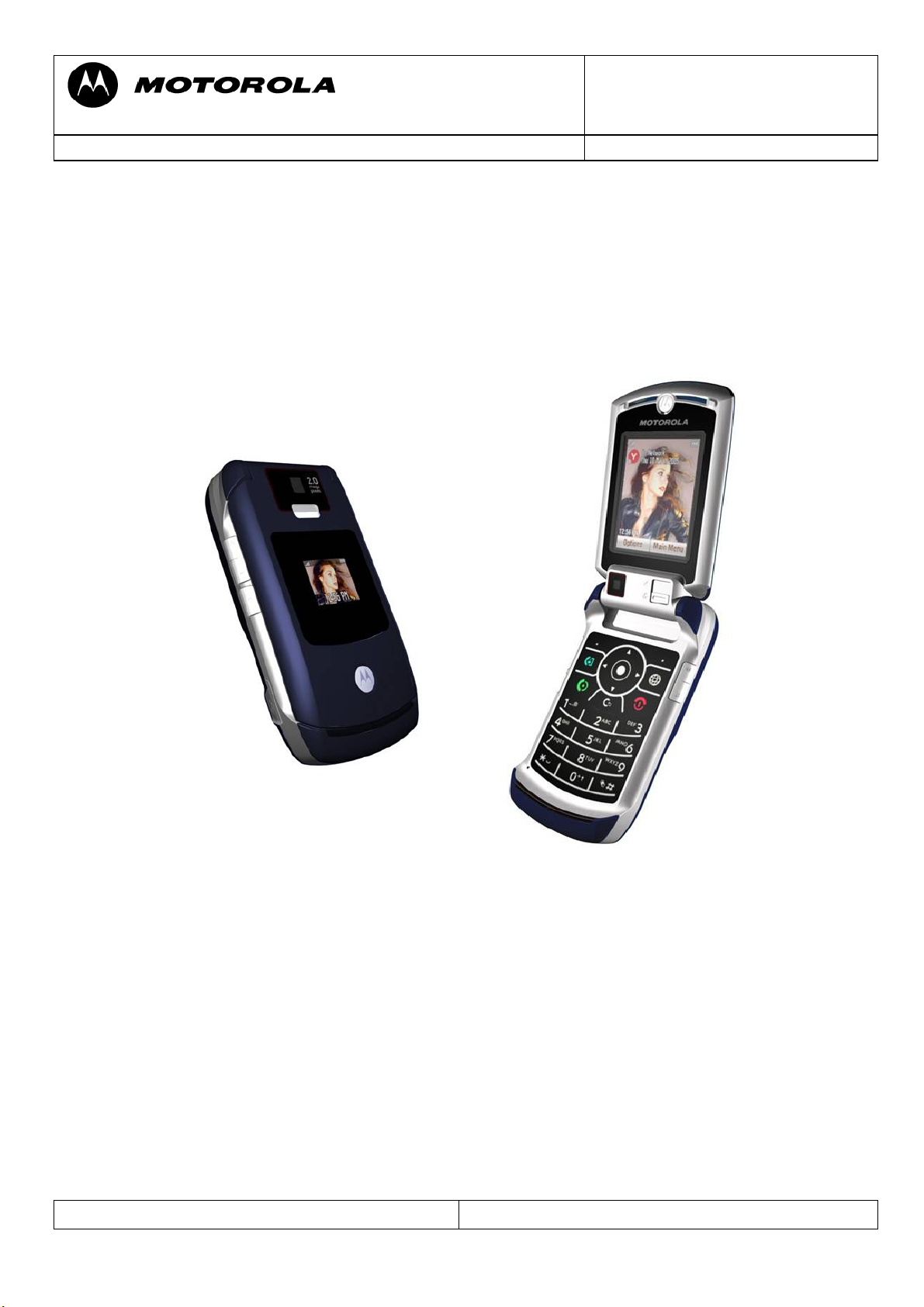
Troubleshooting Guide V3x – Level 3
This document was created to assist analyzers troubleshooting Motorola 3G Phones. All
information was collected during the repair in the Repair Entitlement Group Flensburg.
Repair Support Information
© Copyright 2003-2007 Motorola Inc. All Rights reserved.
Motorola internal use
Page 2
Doc. No: tsg_3g_v3x_level3
Version: 1.1
Motorola GmbH, CSS Center, Mobile Devices
Date: 29.06.2007
Title: Troubleshooting-Guide V3x Level 3 Page: 2 / 26
Contents
Requirements
- System Requirements
- Basic information on troubleshooting Motorola 3G Phones
- Advice on working with lead free soldering/ underfill
Top Ten defect parts
Troubleshooting Guide
- ALTxx
- AUDxx
- BATxx
- CHGxx
- CPRxx
- DAPxx
- DIMxx
- DISxx
- FTRxx
- MKPxx
- OPRxx
- SIKxx
- SIMxx
- TONxx
Follow up faults caused by failed repair actions
Flash procedures
- Software Update
- Recovering Flash memory in Forced Flash Mode
Document Revision History:
Date Version Comment
01.06.2007 1,00 Initial release of document
29.06.2007 1,10 (1) replaced figure in BAT02 section with correct
Repair Support Information
description of VRF_TX_2.775V
© Copyright 2003-2007 Motorola Inc. All Rights reserved.
Motorola internal use
Page 3
Doc. No: tsg_3g_v3x_level3
Version: 1.1
Motorola GmbH, CSS Center, Mobile Devices
Date: 29.06.2007
Title: Troubleshooting-Guide V3x Level 3 Page: 3 / 26
Requirements
- System Requirements
- Power supplies, Oscilloscope, Spectrum Analyzer, Test Set
- preheater for lead free soldering/ soldering machine for BGA´s
- Microscope
- RepairStudio/Radiocomm,
- Field Service Bulletins
- Block diagrams/Schematics
- PinNetFinder FLVIEW
- Basic information on troubleshooting Motorola 3G Phones
- Make sure all contacts are clean, especially the EMU-Connector
- Use newest approved Software
- RESET/MASTERCLEAR can fix some issues
- Do a visual inspection on customer abuse/liquid contamination
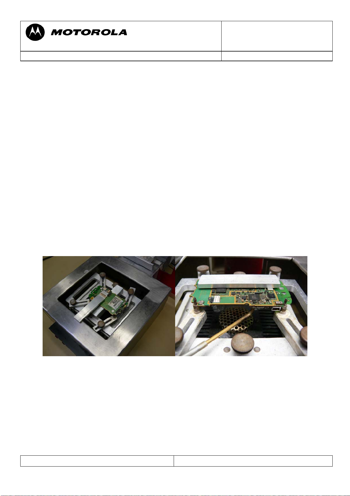
- Advice on working with lead free soldering/ underfill
- Remove heat sensitive parts before soldering
- Work very carefully because of underfilled CPU(U1000) and Harmony (U100)
- Use protection shields / air-cooling equipment
- Useflux for lead free soldering
- Use preheater (HAKKO 853)
use of preheater, protection blocks and air-cooling equipment
Repair Support Information
© Copyright 2003-2007 Motorola Inc. All Rights reserved.
Motorola internal use
Page 4
Motorola GmbH, CSS Center, Mobile Devices
Title: Troubleshooting-Guide V3x Level 3 Page: 4 / 26
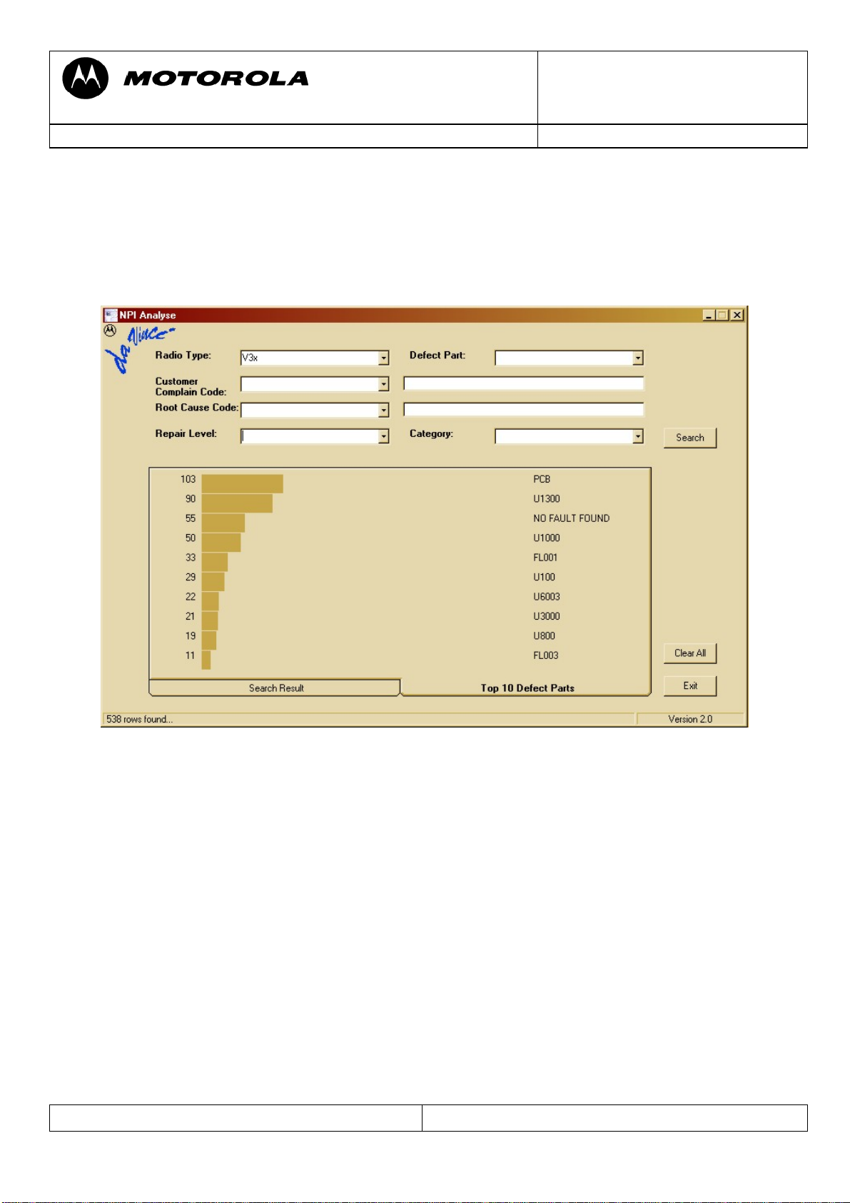
Top Ten defect parts
The following is an analysis summary of the V3x repaired during NPI process by the Repair
Entitlement Group CSS Flensburg
Doc. No: tsg_3g_v3x_level3
Version: 1.1
Date: 29.06.2007
Repair Support Information
© Copyright 2003-2007 Motorola Inc. All Rights reserved.
Motorola internal use
Page 5
Doc. No: tsg_3g_v3x_level3
Version: 1.1
Motorola GmbH, CSS Center, Mobile Devices
Date: 29.06.2007
Title: Troubleshooting-Guide V3x Level 3 Page: 5 / 26
Troubleshooting Guide
First Step
Please make sure beforehand, that the problem at hand is not a SW related issue that can be
solved with a 1FF update and a Master Reset/ Clear. In many cases a simple Master Reset can
already fix the problem.
The following section is meant to be a help in troubleshooting problems which are already
identified as PCB related.
ALT01 Alert – Ring tone, no
ALT02 Alert – Ring tone, low
ALT03 Alert – Ring tone, noise/distortion
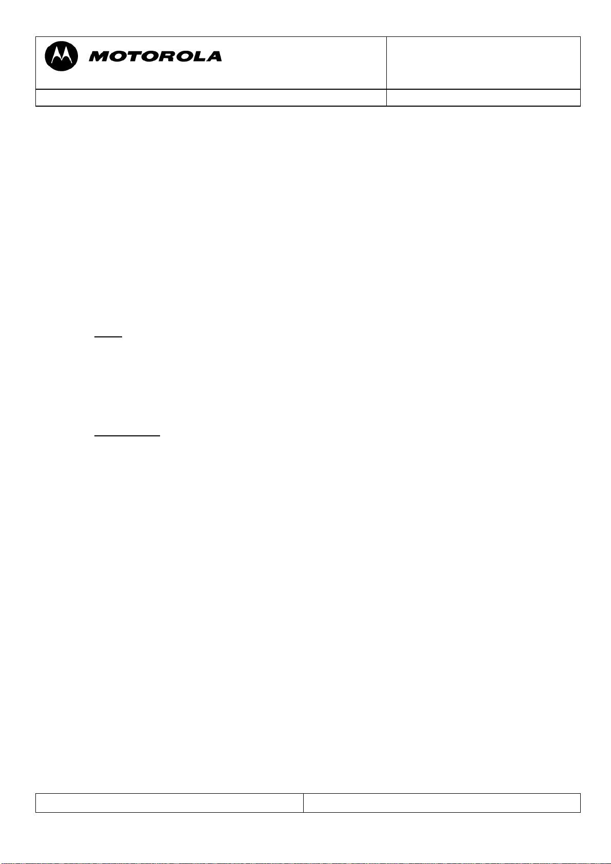
Check LOUD_SPK- (P1) and LOUD_SPK + (P2) – both should have around 2.5Vdc
-
if not check L6009/L6010 for broken connection, VS4200/VS4201/C4203/C4204/
C4212/C4213/C6026/C6027/C6028/C6031 for low resistance
- check ALRT_REF 2.5Vdc at C4210
- check PCB for open tracks from P1 to U3000-F1 / P2 to U3000-H1
- you can either use “Repair-Studio” to switch on 1kHz tone to the alert-speaker to check
for open tracks, but be careful: You can have 1kHz and audio in call at P1/P2, but no
alert-tone, because the PCAP is defect!
- if 1kHz is ok, replace PCAP2 (U3000)
The alert signal is converted to analog and amplified by the PCAP2, but generated by the
POG, so if the PCAP2 alert audio path is ok there could be a problem with the POG not
generating the alert signals.
Repair Support Information
© Copyright 2003-2007 Motorola Inc. All Rights reserved.
Motorola internal use
Page 6
Doc. No: tsg_3g_v3x_level3
Version: 1.1
Motorola GmbH, CSS Center, Mobile Devices
Date: 29.06.2007
Title: Troubleshooting-Guide V3x Level 3 Page: 6 / 26
ALT11 Alert – Vibrator, no
ALT12 Alert – Vibrator, weak
Turn on vibrator using Repair Studio/Radiocomm. Measure V_VIB – should be about 1.3
Vdc. V_VIB is provided directly by the PCAP (U3000). To verify if the vibrator is defective a
simple method is to provide a supply voltage (1Vdc should be enough) via test probes directly
on the vibrator M3000 (radio in off state!). It should be rotating, if not replace the vibrator
M3000. Otherwise replace PCAP (U3000).
Repair Support Information
© Copyright 2003-2007 Motorola Inc. All Rights reserved.
Motorola internal use
Page 7
Doc. No: tsg_3g_v3x_level3
Version: 1.1
Motorola GmbH, CSS Center, Mobile Devices
Date: 29.06.2007
Title: Troubleshooting-Guide V3x Level 3 Page: 7 / 26
AUDxx Audio problems
First step on every audio related problem is to identify which audio paths are affected.
If the audio signals in a loop are ok, there could be an audio problem in a network call. This
could be due to a POG related defect.
AUDxx Audio –
Headset Detection problem
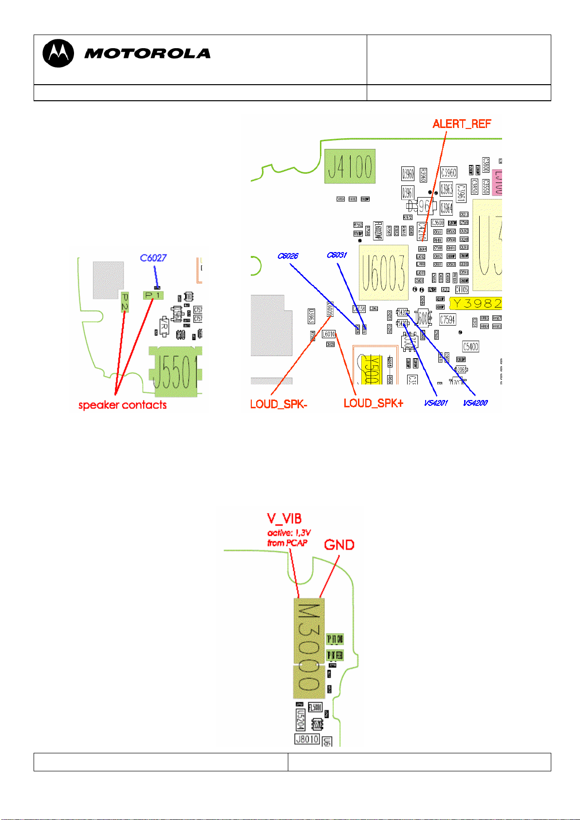
If the headset detection is not working correctly, there is most likely a problem with the
detection of any accessory connected to the EMU connector (J5501).
With an open J5501 the voltage at pin 4 of J5501 (USB_ID) should be 2,775V when phone is
powered on with battery.
For headset detection USB_ID line is used. With headset connected voltage on that line
should be 1,7V.
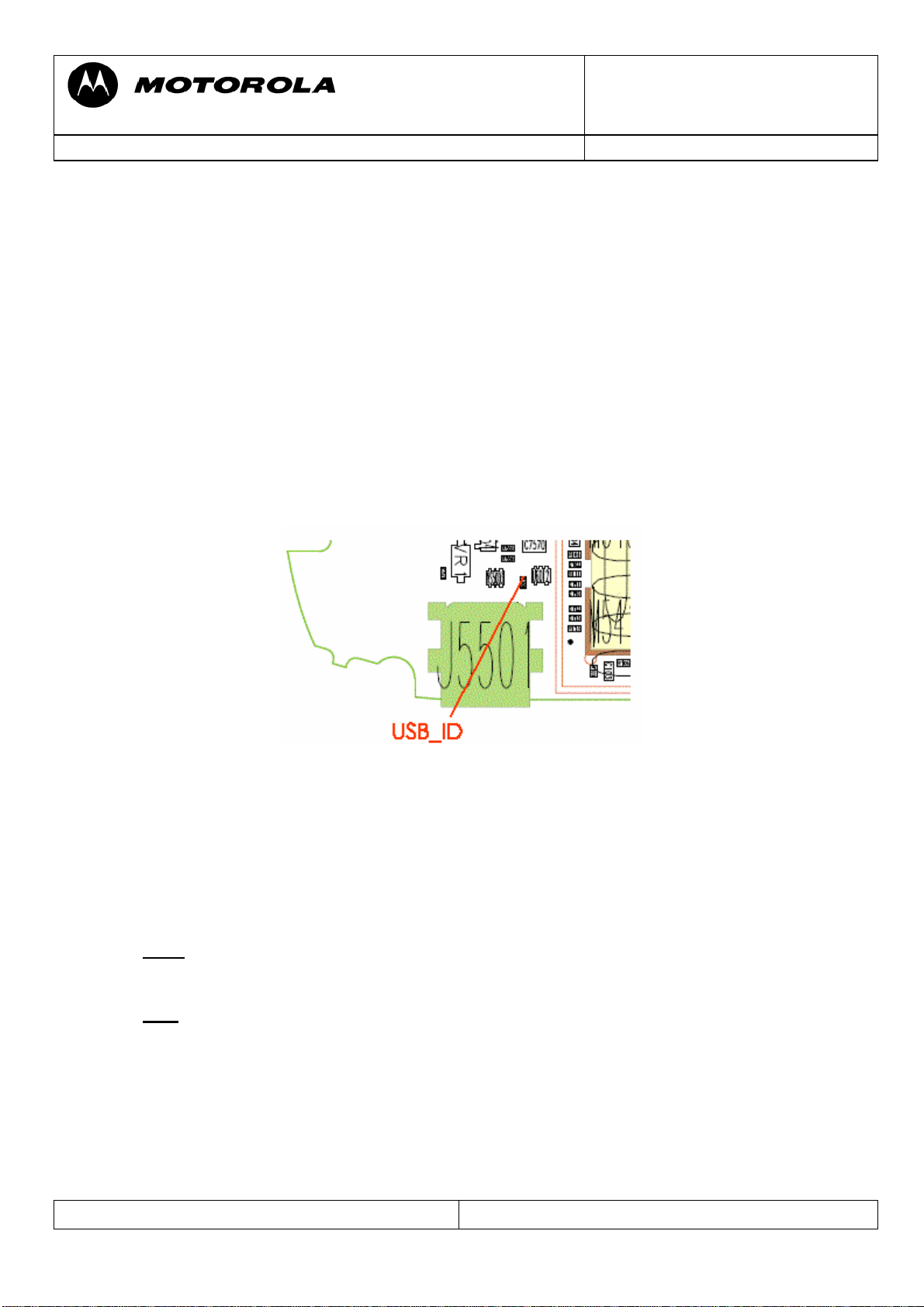
AUD01 Audio – Earpiece, No
AUD02 Audio – Earpiece, Low
Check EAR_SPKR- at C5207 and EAR_SPKR+ at C5208. Both should have around 1.4Vdc
offset voltage, if audio-loop is switched on and additional up to 3Vpp at 1kHz, if test-tone is
switched on.
- if not check J5212 for solder shorts, C5207/5208 for low resistance
- (eventually) check PCB on open tracks from C5207 to C4001/U3000-J4 and C5208 to
C4000/U3000-K2
- if ok, replace PCAP2 (U3000)
Repair Support Information
© Copyright 2003-2007 Motorola Inc. All Rights reserved.
Motorola internal use
Page 8
Doc. No: tsg_3g_v3x_level3
Version: 1.1
Motorola GmbH, CSS Center, Mobile Devices
Date: 29.06.2007
Title: Troubleshooting-Guide V3x Level 3 Page: 8 / 26
AUD05 Audio – Earpiece, Headset
First check the headset-detection. If ok set radio in headset audio loop (stereo) using Repair
Studio/Radiocomm and generate tone (1kHz).
- check HS_SPKR_R at L6011 / HS_SPKR_L at L6012
if ok replace EMU-IC (U6003)
-
-
if not replace PCAP (U3000)
You cannot check audio signal directly at J5501, because in this case it is used for USBconnection!
Repair Support Information
© Copyright 2003-2007 Motorola Inc. All Rights reserved.
Motorola internal use
Page 9

Doc. No: tsg_3g_v3x_level3
Version: 1.1
Motorola GmbH, CSS Center, Mobile Devices
Date: 29.06.2007
Title: Troubleshooting-Guide V3x Level 3 Page: 9 / 26
AUD07 Audio – Mic, No
AUD08 Audio – Mic, Low
Set radio in audio loop using Repair Studio/Radiocomm
- check Mic BIAS at R4100-2 – should be around 2Vdc
- if not check C4100 for low resistance
- check R4100 (4,7kOhm)
- if ok check AUX_MIC_OUT at C4105 while blowing into the microphone to see the
audio signal caused by the blowing
- if not replace microphone
- if ok replace PCAP2 (U3000)
Repair Support Information
© Copyright 2003-2007 Motorola Inc. All Rights reserved.
Motorola internal use
Page 10

Doc. No: tsg_3g_v3x_level3
Version: 1.1
Motorola GmbH, CSS Center, Mobile Devices
Date: 29.06.2007
Title: Troubleshooting-Guide V3x Level 3 Page: 10 / 26
AUD11 Audio – Mic, Headset
Set radio in headset audio loop using Repair Studio/Radiocomm
- check headset Mic Bias at C7589 (EXT_MIC) – should be around 1.4Vdc
- if not check C4401/ C7589 for low resistance
- if C4401/ C7589 are ok, replace PCAP (U3000)
- if headset Mic BIAS ok:
- check C7588/ C5002 for low resistance and check R4401 /L4400
- if ok
replace EMU-IC (U6003)
BAT02 - Battery life short
BAT03 – Battery can’t turn on phone
BAT06 – Battery gets hot
CHGxx - Charging problems
TON01 – No Turn On (draws high current)
In probably most cases these problems are caused by an off current. First verify whether there
is an off current. If there is an off current, it should be checked whether the device draws
current via battery and/or via external connector.
In case of an off current via battery there should be a low resistance (less than ~200 Ohm)/ or
a short from BATT_P (M5400-1) to GND.
To localize the defective part causing the short/ low resistance a simple way is to freeze the
board with a ice-spray, supply a battery voltage from a power supply using micro clamp-type
test probes, and see which parts are getting warm. This is a very basic and essential method
to troubleshoot off current / high current consumption failures.
Repair Support Information
© Copyright 2003-2007 Motorola Inc. All Rights reserved.
Motorola internal use
Page 11

Doc. No: tsg_3g_v3x_level3
Version: 1.1
Motorola GmbH, CSS Center, Mobile Devices
Date: 29.06.2007
Title: Troubleshooting-Guide V3x Level 3 Page: 11 / 26
The power supply (for BATT_P) should be set to 3.6V with current limitation to 2A. We
strictly recommend using the Power Supply Unit Current Drain Meter to check the current
drain of the PCB.
Shields covering suspected parts should be removed before freezing the PCB.
The PCB should be handled with care. After removing the shields the PCB should be given
some time to cool down slowly before freezing it to far below zero to avoid physical stress to
the multilayer PCB with lead free soldered parts.
In some cases the part, which is getting warm has an internal short itself. After removing this
part the off current should be fixed. For verification check off current or measure resistance
BATT_P (M5400-1) to GND. A new part can be placed.
If the short / low resistance remains after replacing the part which was getting warm, it should
be checked which signals/ voltages this part provides. In the most cases this part will provide
a supply voltage to other parts which can also get warm due to an internal short.
To find out the defective part an easy way is to use the Flensburg Layout Viewer to follow the
signal (check for SHORT_RESISTORS after which the signals possibly could have a changed
name), and to remove the parts one after another, until the short is gone.
Most frequent parts with internal shorts causing these kinds of failures are the PA´s
(U400/U800), the Blue-Module (U900), the Harmony (U100), the Rattler (U200), and the
PCAP (U3000).
1.Example:
- BAT00 – radio draws about 400 mA in standby, no off current
- Q3401/U3000 are getting warm
- Q3401 provides VRF_TX_2.775V for PA via short resistor R801 (using Flensburg
Layout Viewer )
Repair Support Information
© Copyright 2003-2007 Motorola Inc. All Rights reserved.
Motorola internal use
Page 12

Doc. No: tsg_3g_v3x_level3
Version: 1.1
Motorola GmbH, CSS Center, Mobile Devices
Date: 29.06.2007
Title: Troubleshooting-Guide V3x Level 3 Page: 12 / 26
- GSM-PA U800 is also getting warm (see above)
- U800 itself has an internal short. Æ defective U800
2.Example:
- BAT02 – radio draws about 40 mA off current
- Only PCAP is getting warm (checked with ice-spray); nothing else
- PCAP draws off current -> replace PCAP
BAT04 – Invalid Battery
- verify EEPROM_ESD_PROT (M5400-2) while PCB is connected to EMU-USB
cable. It should be 2.775V.
- If it is low, check VS5004, R5401 (4k7) and R5402 (100 Ohm). If they are ok it
should be a problem with the POG U1000
CHG01 – Does not charge
Repair Support Information
© Copyright 2003-2007 Motorola Inc. All Rights reserved.
Motorola internal use
Page 13

Doc. No: tsg_3g_v3x_level3
Version: 1.1
Motorola GmbH, CSS Center, Mobile Devices
Date: 29.06.2007
Title: Troubleshooting-Guide V3x Level 3 Page: 13 / 26
If the phone seems to charge, but battery meter stays at low level, check whether there is a
high current consumption or an off current via battery. If so please follow troubleshooting as
described in the BATxx section of this document.
If there is no off current, check the whole path for the charging current. Make a
battery/charger phasing to see, if only the charger current or also the battery-phasing is
affected. For a charger current problem only:
- Check Q3960, Q3961, R3960
- If ok replace EMU-chip (U6003)
For additional battery phasing problems (for example: battery sense or battery meter) replace
PCAP (U3000)
Battery Thermistor problem
Check BATT_THERM at M5400-3, it should be 2.7Vdc. If it is not check R4903, R4904,
R4907, C4903 for tombstoned/misplaced parts and C4903 for low resistance.
, replace PCAP (U3000).
If ok
Repair Support Information
© Copyright 2003-2007 Motorola Inc. All Rights reserved.
Motorola internal use
Page 14

Doc. No: tsg_3g_v3x_level3
Version: 1.1
Motorola GmbH, CSS Center, Mobile Devices
Date: 29.06.2007
Title: Troubleshooting-Guide V3x Level 3 Page: 14 / 26
CHG02 – No charging indication
If display indicates “Charging not possible” or the phone only powers on while plugging in
the charger, but is not charging. Then check the USB_ID line at J5501 with phone powered
on by battery. It should be 2.7Vdc (2.4Vdc is not enough ! )
- If not check VS5003. USB_ID voltage must be 2.7Vdc, if VS5003 is removed
- Check voltage at R7606-1 (2.7Vdc) and check U6012
- If ok replace U6003
CPR01 – Voice call - Can’t make
CPR02 – Voice call - Can’t receive call
CPR03 – Voice call – no service
First step in every Call related problem should be to figure out whether there is a receiving
problem or a transmitting problem and which bands are affected.
Make sure, that the RF connector (N001) is cleaned (with cleaner or alcohol) before making a
phasing/call-processing test or if the test fails!
No TX GSM900 (1800/1900)
Let radio transmit on GSM900 using Repair Studio/Radiocomm. Make sure to provide a
battery voltage via micro clamp-type test probes to battery contacts M5400, because the main
power supply for the PA modules is taken only from the battery.
- Check GSM_TX at L213
- if ok in size and form (if unsure compare to good radio) check FL001
If the power is only a few dB below the min limit during TX phasing, the problem is a high
signal loss caused by a defect FL001 or RF connector (N001). If the problem only exists on
GSM900 band, it is most likely a defect FL001. If the high frequencies (1800/1900MHz) are
faulty, it is a problem by a defect RF connector (N001). You can check the loss for DCS
1800 MHz without removing the PA shield, because PA output can be checked at FL004
(DCS_PCS_TX).
Repair Support Information
© Copyright 2003-2007 Motorola Inc. All Rights reserved.
Motorola internal use
Page 15

Doc. No: tsg_3g_v3x_level3
Version: 1.1
Motorola GmbH, CSS Center, Mobile Devices
Date: 29.06.2007
Title: Troubleshooting-Guide V3x Level 3 Page: 15 / 26
- if TX at L213 is not ok check PA input (MB_LB_RF) at R802
- if MB_LB_EN is good, following signals should be present:
- VRF_PA_REF_2.775V at C806
- PA_BATT+ at C802
- LB_EN at C807 (pulsed 3V at 217Hz) – signal from Harmony
- GSM_PA_VBA (pulsed at 217 Hz) at R807 is proportional to the expected
amplification of the PA. Normal values are about 750mV at low power and 2,1V at
max. power. With a defect PA it can grow up to 2,7V at low power!
- TX_EN_2V7 and 9E_MODE are two more signals coming from Harmony directly to
the PA that do not have test points.
If VRF_PA_REF_2.775V is missing or low, it’s probably not correctly generated by the
PCAP or is being pulled down by a defective part which most probably will get warm – and
can easily be found by a thermal troubleshooting as described in the BATxx section of this
document. VRF_PA_REF_2.775V is the same as VRF_TX_2.775V and supplies both PAs
U800 and U400, the Rattler IC U200 and the Harmony U100.
If PA_BATT+ is missing check L800 and R3961. If LB_EN is missing it’s probably a
defective Harmony.
- if MB_LB_RF is bad it’s probably a problem with the Blue Module U900 or with the
POG (Analyzer set to: SWEEP – 1s; SPAN – 1,4MHz)
Repair Support Information
© Copyright 2003-2007 Motorola Inc. All Rights reserved.
Motorola internal use
Page 16

Doc. No: tsg_3g_v3x_level3
Version: 1.1
Motorola GmbH, CSS Center, Mobile Devices
Date: 29.06.2007
Title: Troubleshooting-Guide V3x Level 3 Page: 16 / 26
No TX WCDMA
Let radio transmit on WCDMA using Repair Studio/Radiocomm. Make sure to provide a
battery voltage via micro clamp-type test probes to battery contacts M5400.
- Check WB_TX at C411 – if ok in size and form (if unsure compare to good radio)
check FL003, FL001
- Size and form of WCDMA TX signal:
(Analyzer set to: SPAN – 10MHz)
- If not ok
check PA input at C221
- If PA input is good, check supply voltages VRF_PA_REF_2.775V at C402 and
PA_BATT+ at C400/C802, TX_WB_EN at C403 about 2.7Vdc (WCDMA TX Enable
signal from Harmony). If all of these signals are present, WCDMA PA U400 is most
properly defective.
- If PA input is bad, check the signals to U200: TX_EN (2.7Vdc from Harmony) at
TP205, SW_VCO_EN (2.7Vdc from Harmony) at TP210, REF (26 MHz clock from
Blue Module) at R213.
Also check the TX I and Q signals.
If all of these are present, it is most
likely a defective or badly soldered
Rattler IC (U200).
Repair Support Information
© Copyright 2003-2007 Motorola Inc. All Rights reserved.
Motorola internal use
Page 17

Doc. No: tsg_3g_v3x_level3
Version: 1.1
Motorola GmbH, CSS Center, Mobile Devices
Date: 29.06.2007
Title: Troubleshooting-Guide V3x Level 3 Page: 17 / 26
WCDMA TX I/Q signal
- If one of these signals (except 26 MHz REF) is missing, Harmony (U100) is most
properly defective.
No RX GSM900 (1800/1900)
Inject a RF from Test Set. Check ANT_SW_RX at antenna switch N001-1. Check for
presence of MB_GSM at R914 (MB_DCS at R913 / MB_PCS atR912).
- If not ok
- If ok
replace FEM FL001
there is most likely a problem with the Blue Module U900 or the Harmony U100
No RX WCDMA
WCDMA RX is not passing FL001. If WCDMA RX fails, Blue Module (U900) or the
Harmony (U100) could be the problem.
Note: For AFC phasing the receiver is used. So, if there is any RX fail, the AFC
phasing on that frequency band also fails. If the RX phasing is ok, but only AFC
phasing fails, a bad crystal is the most likely cause.
- replace Y500
Repair Support Information
© Copyright 2003-2007 Motorola Inc. All Rights reserved.
Motorola internal use
Page 18

Doc. No: tsg_3g_v3x_level3
Version: 1.1
Motorola GmbH, CSS Center, Mobile Devices
Date: 29.06.2007
Title: Troubleshooting-Guide V3x Level 3 Page: 18 / 26
DAP11 – Data Application – cannot upgrade software
OPR03 – Operation – Error Message
Make sure, that you have adjusted 5Vdc on your power supply for the EMU-cable and the
phone SW is not newer than the 1FF-file. Watch the display when entering the flash-mode. If
an error message appears, do following action:
- for “critical error 01 13”: The POG (U1000) is defect.
- for “critical error 01 1B”: The POG (U1000) is defect
- for “critical error 10 39”: The RAM-downloader of 1FF-file does not match with
phone bootloader. Use the newest/ right 1FF-file
Otherwise go to the TONxx section in this document.
DIM01 – Display Main – no display
DIM08 - Display Main – No backlight
DIM09 – Display Main – Low/Dim backlight
DIS01 – Display Secondary – no display
DIS07 – Display Secondary – No backlight
DIS08 – Display Secondary – Low/Dim backlight
DAP10 – Data Application – poor picture quality
Make sure that the problem is not located in the Flip Assembly, by testing PCB with a good
one and do an optical check of J5212.
The following supply voltages for the Flip Assembly should be present:
- VCAM_2.6V at C5203
- V3_1.875V at C7591
- VMAIN_1.55V at C5204
- VAUX1_2.775V at C7590 (generated by Q3703)
- B+ at C5205/C5206
The voltages can be ok without a flip connected, but can break down, if a flip is plugged in,
although the flip is ok! Additionally check the clock signal:
- PS_CLK_MM_C at C7608 (should be 13 MHz)
only present the first seconds after power on!
If ok check:
- Filters U5202/U5204/U6011 and Diode VS5201
- Filters FL5000/FL5001 (look especially for broken part!)
If ok, replace U5200 and U5201 (sometimes they are badly soldered only)
You can check the function of these parts by using an Ohm Meter to check the resistance to
GND for verification, which line is affected. By using the FLViewer it can be tracked which
filters the signal passes until it reaches the POG.
If all of these are ok, it should most likely be a problem with the POG.
Repair Support Information
© Copyright 2003-2007 Motorola Inc. All Rights reserved.
Motorola internal use
Page 19

Doc. No: tsg_3g_v3x_level3
Version: 1.1
Motorola GmbH, CSS Center, Mobile Devices
Date: 29.06.2007
Title: Troubleshooting-Guide V3x Level 3 Page: 19 / 26
DIM01 – Display Main – No display
MKP01 – Main Keypad – No Function/hangs
TON01 – Turn on/off – No turn on
Flip detect problem
Units with a flip detect problem will show following symptoms:
- no power on via battery
- no main display via EMU connector supply
- CLI display is not switching on open/close flip
- no keypad function
Check FLIP_DETECT_C at R5117 – should be 2.7Vdc (High), if it is low check
- R5117 itself
- Check Filter U5104 for broken part/solder short
- Replace Filter U5104
- Check FLIP_DETECT_C at R5117 again
- If FLIP_DETECT_C is 2.7Vdc (High) now, the Filter U5104 was defective
- If not, the POG is defect
FTR07 – Feature – MMS Video Clip
Capturing of video is possible, but no playback and saving is possible. Make sure that phone
was reflashed with 1FF-file.
- Check for an error message
- If phone fails with “access device”, camera is ok and it is possible to view previously
taken pictures, this fault can be caused by a defective memory part. Multimedia data is
stored in the DOC (disc on chip), which is one package with the SDRAM (U6004).
- Replace SDRAM/DOC (U6004)
- If not successful, POG (U1000) is defect
Repair Support Information
© Copyright 2003-2007 Motorola Inc. All Rights reserved.
Motorola internal use
Page 20

Doc. No: tsg_3g_v3x_level3
Version: 1.1
Motorola GmbH, CSS Center, Mobile Devices
Date: 29.06.2007
Title: Troubleshooting-Guide V3x Level 3 Page: 20 / 26
MKP01 – Main Keypad – No function/hangs
SIK01 – Side Keys – No function
Due to the keypad matrix architecture with 8 rows in 4 columns it is quite useful to verify
which keys (if not all) are affected. By knowing which keys are not working, it is possible to
find out which row or column is affected. You can either use an Ohm Meter to check the
resistance to GND for verification, which line is affected. By using the FLViewer it can be
tracked which filters the signal passes until it reaches the POG.
In practice the defective part can very often be found by doing a visual inspection. Check:
- U5100
- U5101
- U5104 for solder shorts/broken part
If the keypad connector/Filters are ok it’s probably a problem with the POG.
MKP05 – Main Keypad – No/Dim backlight
First check keypad connector J5100! Turn on keypad backlight using Repair
Studio/Radiocomm. Check VBOOST_5.5V at R6021-1.
- If not ok, only 4 – 5Vdc (same as B+) or high current with keypad connected,
check/replace L3100. If L3100 ok, replace PCAP (U3000).
- If VBOOST_5.5V is ok, check R6021/R7626 (5,5Vdc must be present at R7626-2
also)
- If ok, check KPD_LED_EL_EN1 (2,7Vdc) at R6023, KPD_LED_EL_EN2 (1,8Vdc)
at C7613 with backlight turned on.
- If not ok, remove U5104 and check again. If ok, place new Filter. If not, POG
(U1000) is defect.
SIM01 – SIM card – check card/insert SIM
Measurement on the SIM interface is a little bit difficult, as not all signals will be present until
a SIM card and a battery are inserted. As far as I know there is still no SIM feature
implementation in Repair Studio or Radiocomm. In the most cases it should be possible to
figure out which part is defective by simply using the Ohm Meter to measure the following
signals to GND:
- VSIM_CARD at J8005-2,J8005-3, C5503-2, C3850
If far less than 30 kOhm to GND, it could be a defective PCAP (U3000)
- USIM_CLK at J8005-5
- USIM_IO at J8005-7
Repair Support Information
© Copyright 2003-2007 Motorola Inc. All Rights reserved.
Motorola internal use
Page 21

Doc. No: tsg_3g_v3x_level3
Version: 1.1
Motorola GmbH, CSS Center, Mobile Devices
Date: 29.06.2007
Title: Troubleshooting-Guide V3x Level 3 Page: 21 / 26
- USIM_RST at J8005-9, C3911-2
If any of these has far less than 30 kOhm to GND, it could be a defective POG (U1000).
Before replacing the PCAP (U3000) or the POG (U1000) make sure that none of the
associated capacitors have low resistance to GND.
The VSIM_CARD can also be checked with the oscilloscope. First put the probe to the test
point (C5503-2) and then switch on the phone (by switching the output of the power supply).
After a few seconds the VSIM_CARD (2,7Vdc) should appear for about one second.
The same can be done with VSIMC_EN at TP3002. It is the enable signal for VSIM_CARD.
While it goes to high level (2,7Vdc)VSIM_CARD is switched on.
TON01 – No Turn On
Verify if radio doesn’t turn on (assembled with display). If it does, but doesn’t enumerate via
EMU-Connector at RSD/Repair studio there should be a problem with the USB connection.
In some cases a 1FF SW reflash in FORCED FLASH MODE (by connecting EMUConnector to radio while “*” and “#” are pressed) can fix this issue.
- If not, visually check EMU Connector for mechanical defects or contamination on
contacts, bad soldered pins or solder shorts
- Check the DP_RXD line at VS5003-3 (J5501-3) and DM_TXD line at VS5003-1
(J5501-2) with an ohm meter to GND to make sure, that there is no short to GND or
an open track
- Check R3651, R3652, R7587, R7588 for high resistance
- If ok, replace EMU-chip (U6003)
- Check again
- If not ok, the POG (U1000) is defect
The USB interface is located in the POG, but the data bus is switched through by the EMUchip (U6003).
Repair Support Information
© Copyright 2003-2007 Motorola Inc. All Rights reserved.
Motorola internal use
Page 22

Doc. No: tsg_3g_v3x_level3
Version: 1.1
Motorola GmbH, CSS Center, Mobile Devices
Date: 29.06.2007
Title: Troubleshooting-Guide V3x Level 3 Page: 22 / 26
If the radio doesn’t turn on, but draws high current (>500 mA)
- Please follow troubleshooting instructions as described in the BATxx section of this
document.
Note:
- Watchdog
In case the phone draws current but switches off after a few seconds, you can force the phone
not to switch off, by setting the Watchdog R3250DNP. By placing a short resistor as R3250,
or by just solder across the pads of R3250 the WATCHDOG signal will be pulled to HIGH
(VLVIO_1.875V) and the PCAP will not switch off its power regulators. You will then be able
to measure all the voltages or to do a thermal troubleshooting by using ice- spray.
- “power switch”
The second way to check the voltages is to use a switch in the plus line of your power supply.
You can put the probe to the test points of each voltage and view the voltages appearing for a
short time (half a second) during each switching action.
If radio draws no current at all (also not for a short time) it’s most likely a problem with the
32.768 KHz clock generated by Y3982
- replace Crystal Y3982
- if
unsuccessful, replace PCAP (U3000)
Repair Support Information
© Copyright 2003-2007 Motorola Inc. All Rights reserved.
Motorola internal use
Page 23

Doc. No: tsg_3g_v3x_level3
Version: 1.1
Motorola GmbH, CSS Center, Mobile Devices
Date: 29.06.2007
Title: Troubleshooting-Guide V3x Level 3 Page: 23 / 26
If the current consumption is in normal range (40mA to 300mA)
- try doing a 1FF SW reflash in FORCED FLASH MODE. If radio enters the forced
flash mode or starts in flash mode by itself the main supply voltages for the logic
section should be ok – Most likely the trouble can be found in the logic section
(POG/Flash Memory/SDRAM Memory). For “critical error xx xx” go to the DAPxx
section of this document.
- if unsuccessful, a flash log file generated by Repair Studio/RSD can be viewed. There
you will find the reason for the flash operation failure. However, this information can
be ignored, as in almost every case the next step will be to send the PCB to a Level4
service-center, because POG (U1000) or Flash (U1300) is defect.
If the phone enters flash mode by itself as “S Blank Rainbow POG” at Repair-Studio/RSDlite,
the POG cannot recognize any flash:
send the PCB to a Level4 service-center, because POG (U1000) or Flash (U1300) is
defect.
If the phone doesn’t enter flash mode, but draws current the following signals should be
checked:
- VPOG_LVIO_1.875V which becomes POG_LVIO after passing short R1010 /
VSDRAM_DOC_IO after passing Short R7617
- VLVIO_1.875V which is only used for FLASH / SDRAM and Harmony
- VMAIN_1.55V
- 32.768KHz clock at Y3982
If one of them is missing or low, check current consumption. If it is high something might be
getting warm – follow the thermal troubleshooting routine as described in the BATxx section
of this document.
Otherwise replace PCAP (U3000).
If voltages are ok, FLASH and POG already replaced and the USB-bus is checked, but phone
appears as a “unknown device” for the computer, it is most likely a problem by the
SDRAM/DOC (U6004).
Repair Support Information
© Copyright 2003-2007 Motorola Inc. All Rights reserved.
Motorola internal use
Page 24

Doc. No: tsg_3g_v3x_level3
Version: 1.1
Motorola GmbH, CSS Center, Mobile Devices
Date: 29.06.2007
Title: Troubleshooting-Guide V3x Level 3 Page: 24 / 26
TON01 – Turn on/off – No turn on
TON06 – Turn on/off – No turn off
MKP01 – Main Keypad – No function/hangs (On/Off switch)
On/Off switch not working
Check U5104 for broken part/solder short and make a visual inspection of J8000. If it seems
visually ok, there might be a defective part.
- Check voltage at ON_OFF_ENDB_C (J8000-11). It should have same level as B+ (for
example: 4Vdc)
- If not ok, check ON_OFF_ENDB at R7610-2 (same level as B+)
- If ok, replace U5104
ON_OFF_ENDB is not ok, check R7610 and C7614
- If
- If ok,
replace U5104
- If unsuccessful, replace PCAP (U3000)
TON03 – Turn on/off – auto power down in standby
If phone stores panic: DSM_MEASUREMENT_ERROR there is most properly a problem
with the 32.768 KHz clock, which is needed for the whole radio when in deep sleep mode.
Replace Y3982, test radio with a network SIM card and let radio enter deep sleep mode.
- if radio still powers down, replace PCAP (U3000)
Repair Support Information
© Copyright 2003-2007 Motorola Inc. All Rights reserved.
Motorola internal use
Page 25

Doc. No: tsg_3g_v3x_level3
Version: 1.1
Motorola GmbH, CSS Center, Mobile Devices
Date: 29.06.2007
Title: Troubleshooting-Guide V3x Level 3 Page: 25 / 26
TON03 – Turn on/off – auto power down in standby
TON01 – Turn on/off – No turn on
If the phone attempts to start (you can sometimes see “Hellomoto” screen), but always
powercycles instead of fully powering up, it is most likely a problem with the communication
of the POG and the other components like Harmony (U100), Blue Module (U900) and GPU
(inside the flip). In this case a reflash in forced flash mode is always possible, but would not
solve the problem.
The problem is to determine, which component fails.
- If the PCB standalone is working, but is powercycling with a flip connected, it is a
problem with the connection between POG and GPU. – follow troubleshooting as
described in the DIMxx section of this document.
- If not, it is most likely a problem with the Harmony (U100), because the underfill
below U100 is very sensitive against temperatures above 180 degrees.
- If phone draws about 200mA for +/-10 seconds, reflash is possible, but the fault is the
same after that, the Harmony (U100) or Blue Module (U900) will be the problem.
Follow up faults caused by failed repair actions
Quite a lot of repairs which were sent to Level 4 service have a second fault, which is caused
by an unsuccessful repair attempt.
We strictly recommend to visually check the PCB for skewed or tombstoned parts, solder
shorts or heat bubbles in PCB after every soldering action. Especially small parts which are
located close to shields can easily be misplaced during removal or setting of the shields.
We found that some parts seem to be more heat sensitive than others. We had some issues
with defective RattlerICs (U200) after replacing the GSM PA (U800). In these cases there
could be an off current or high standby current consumption and trouble with TX power in
WCDMA.
The main problems on the V3x are surely the underfilled Harmony and POG. So it is
very important to use the special cooling equipment for solder actions on the PCB!
Especially solder actions in the PA-section will cause problems with the underfill of POG
(U1000) and Harmony (U100) with which the level 4 service then has to deal with!
The replacement of the PCAP (U3000) requires air-cooling of the Harmony (U100)!
Flash procedures
Note: It is very important to do a restart after every flash process! Otherwise the phone will
start in flash mode again.
Software update
Following steps are necessary to update the Software to latest approved Software:
- unlock phone (if subsidy locked)
- flash customer specific 1FF superfile (example: DC One File Flash:
R252211LD_U_85.92.70R_LP0039_DRM0003_VSTU_206_080C_JPGE_R25221VFSIRIUS_26_USRAZRV3XVFDE25221050_1
FF.shx
)
Repair Support Information
© Copyright 2003-2007 Motorola Inc. All Rights reserved.
Motorola internal use
Page 26

Doc. No: tsg_3g_v3x_level3
Version: 1.1
Motorola GmbH, CSS Center, Mobile Devices
Date: 29.06.2007
Title: Troubleshooting-Guide V3x Level 3 Page: 26 / 26
- after restart:
- take out of “In Factory” – if necessary
- do Master Reset/Master Clear
Recovering Flash Memory in Forced Flash Mode
If the phone doesn’t start because of corrupted software it might be possible to recover it:
- connect phone to EMU-cable while pressing “*” and “#”
The phone should start in flash mode now: S Flash Rainbow POG.
- flash 1FF superfile (example: DC One File Flash:
R252211LD_U_85.92.70R_LP0039_DRM0003_VSTU_206_080C_JPGE_R25221VFSIRIUS_26_USRAZRV3XVFDE25221050_1
FF.shx
)
- after restart:
- do Master Reset/Master Clear
If the phone doesn’t start in flash mode or as: S Blank Rainbow POG, there is a problem.
Please follow troubleshooting instructions as described in the TON01 section of the
Troubleshooting-Guide.
Repair Support Information
© Copyright 2003-2007 Motorola Inc. All Rights reserved.
Motorola internal use
 Loading...