

Page 1
Level 1 and 2 Service Manual
V3x
Digital Wireless Telephone
6809497A15-A
UMTS 2100, GSM 900/1800/1900 GPRS
Page 2

Page 3

1 and 2
V3x
Level 1 and 2 Service Manual Contents
6809497A15-A
Contents
Introduction . . . . . . . . . . . . . . . . . . . . . . . . . . . . . . . . . . . . . . . . . . . . . . . . . . . . . . . . . . . . . . . . . . . . . . . . . . . . . . 5
Product Identification . . . . . . . . . . . . . . . . . . . . . . . . . . . . . . . . . . . . . . . . . . . . . . . . . . . . . . . . . . . . . . . . 5
Product Names . . . . . . . . . . . . . . . . . . . . . . . . . . . . . . . . . . . . . . . . . . . . . . . . . . . . . . . . . . . . . . . . . . . . . 5
Product Changes . . . . . . . . . . . . . . . . . . . . . . . . . . . . . . . . . . . . . . . . . . . . . . . . . . . . . . . . . . . . . . . . . . . . 5
Regulatory Agency Compliance . . . . . . . . . . . . . . . . . . . . . . . . . . . . . . . . . . . . . . . . . . . . . . . . . . . . . . . . 5
Computer Program Copyrights . . . . . . . . . . . . . . . . . . . . . . . . . . . . . . . . . . . . . . . . . . . . . . . . . . . . . . . . 6
About This Service Manual . . . . . . . . . . . . . . . . . . . . . . . . . . . . . . . . . . . . . . . . . . . . . . . . . . . . . . . . . . . 6
Warranty Service Policy . . . . . . . . . . . . . . . . . . . . . . . . . . . . . . . . . . . . . . . . . . . . . . . . . . . . . . . . . . . . . . 7
Parts Replacement . . . . . . . . . . . . . . . . . . . . . . . . . . . . . . . . . . . . . . . . . . . . . . . . . . . . . . . . . . . . . . . . . . 8
Product Overview . . . . . . . . . . . . . . . . . . . . . . . . . . . . . . . . . . . . . . . . . . . . . . . . . . . . . . . . . . . . . . . . . . . . . . . . 11
Features . . . . . . . . . . . . . . . . . . . . . . . . . . . . . . . . . . . . . . . . . . . . . . . . . . . . . . . . . . . . . . . . . . . . . . . . . . 11
General Operation . . . . . . . . . . . . . . . . . . . . . . . . . . . . . . . . . . . . . . . . . . . . . . . . . . . . . . . . . . . . . . . . . . . . . . . . 14
Controls, Indicators, and Input / Output (I/O) Connections . . . . . . . . . . . . . . . . . . . . . . . . . . . . . . . . . 14
Alert Settings . . . . . . . . . . . . . . . . . . . . . . . . . . . . . . . . . . . . . . . . . . . . . . . . . . . . . . . . . . . . . . . . . . . . . 15
Battery Function . . . . . . . . . . . . . . . . . . . . . . . . . . . . . . . . . . . . . . . . . . . . . . . . . . . . . . . . . . . . . . . . . . . 15
Operation . . . . . . . . . . . . . . . . . . . . . . . . . . . . . . . . . . . . . . . . . . . . . . . . . . . . . . . . . . . . . . . . . . . . . . . . . 16
Tools and Test Equipment . . . . . . . . . . . . . . . . . . . . . . . . . . . . . . . . . . . . . . . . . . . . . . . . . . . . . . . . . . . . . . . . . 17
Disassembly . . . . . . . . . . . . . . . . . . . . . . . . . . . . . . . . . . . . . . . . . . . . . . . . . . . . . . . . . . . . . . . . . . . . . . . . . . . . . 18
Removing and Replacing the Battery Cover and Battery . . . . . . . . . . . . . . . . . . . . . . . . . . . . . . . . . . 18
Removing and Replacing the Subscriber Identity Module (SIM) . . . . . . . . . . . . . . . . . . . . . . . . . . . . . 20
Removing and Replacing the Antenna Cover . . . . . . . . . . . . . . . . . . . . . . . . . . . . . . . . . . . . . . . . . . . . 21
Removing and Replacing the Rear Housing . . . . . . . . . . . . . . . . . . . . . . . . . . . . . . . . . . . . . . . . . . . . . 22
Removing and Replacing the Transceiver Board Assembly . . . . . . . . . . . . . . . . . . . . . . . . . . . . . . . . . 24
Removing and Replacing the Popple Dome PC Board . . . . . . . . . . . . . . . . . . . . . . . . . . . . . . . . . . . . . 28
Removing and Replacing the Keypad, Volume/Smart, and Voice Keys . . . . . . . . . . . . . . . . . . . . . . . . 29
Removing and Replacing the Flip Assembly . . . . . . . . . . . . . . . . . . . . . . . . . . . . . . . . . . . . . . . . . . . . . 31
Removing and Replacing the Flip Cover . . . . . . . . . . . . . . . . . . . . . . . . . . . . . . . . . . . . . . . . . . . . . . . . 32
Removing and Replacing the Flip Display Assembly . . . . . . . . . . . . . . . . . . . . . . . . . . . . . . . . . . . . . . 36
Subscriber Identity Module (SIM) and Identification . . . . . . . . . . . . . . . . . . . . . . . . . . . . . . . . . . . . . . . . . . . . 40
SIM Card . . . . . . . . . . . . . . . . . . . . . . . . . . . . . . . . . . . . . . . . . . . . . . . . . . . . . . . . . . . . . . . . . . . . . . . . . 40
Personality Transfer . . . . . . . . . . . . . . . . . . . . . . . . . . . . . . . . . . . . . . . . . . . . . . . . . . . . . . . . . . . . . . . . 40
Identification . . . . . . . . . . . . . . . . . . . . . . . . . . . . . . . . . . . . . . . . . . . . . . . . . . . . . . . . . . . . . . . . . . . . . . 40
Troubleshooting . . . . . . . . . . . . . . . . . . . . . . . . . . . . . . . . . . . . . . . . . . . . . . . . . . . . . . . . . . . . . . . . . . . . . . . . . 42
Programming: Software Upgrade and Flexing . . . . . . . . . . . . . . . . . . . . . . . . . . . . . . . . . . . . . . . . . . . 44
Part Numbers . . . . . . . . . . . . . . . . . . . . . . . . . . . . . . . . . . . . . . . . . . . . . . . . . . . . . . . . . . . . . . . . . . . . . . . . . . . . 45
Related Publications . . . . . . . . . . . . . . . . . . . . . . . . . . . . . . . . . . . . . . . . . . . . . . . . . . . . . . . . . . . . . . . . 45
Exploded View Diagram . . . . . . . . . . . . . . . . . . . . . . . . . . . . . . . . . . . . . . . . . . . . . . . . . . . . . . . . . . . . . 46
Exploded View Parts List . . . . . . . . . . . . . . . . . . . . . . . . . . . . . . . . . . . . . . . . . . . . . . . . . . . . . . . . . . . . 47
6809497A15-A January 31, 2006 3
Page 4

Contents V3x
4 January 31, 2006 6809497A15-A
Page 5

1 and 2
V3x
Level 1 and 2 Service Manual Introduction
6809497A15-A
Introduction
Motorola® Inc. maintains a worldwide organization that is dedicated to provide
responsive, full-service customer support. Motorola products are serviced by an
international network of company-operated product-care centers as well as
authorized independent service firms.
Available on a contract basis, Motorola Inc. offers comprehensive maintenance and
installation programs that allow customers to meet requirements for reliable,
continuous communications.
To learn more about the wide range of Motorola service programs, contact your local
Motorola products representative or the nearest Customer Service Manager.
Product Identification
Motorola products are identified by the model number on a label usually located
under the battery. Use the entire model number when inquiring about the product.
Numbers are also assigned to chassis and kits. Use these numbers when requesting
information or ordering replacement parts.
Product Names
Product names are listed on the front cover. Product names are subject to change
without notice. Some product names, as well as some frequency bands, are available
only in certain markets.
Product Changes
When electrical, mechanical or production changes are incorporated into Motorola
products, a revision letter is assigned to the chassis or kit affected, for example;
-A, -B, or -C, and so on.
The chassis or kit number, complete with revision number, is imprinted during
production. The revision letter is an integral part of the chassis or kit number and
is also listed on schematic diagrams and printed-circuit board layouts.
Regulatory Agency Compliance
This device complies with Part 15 of the FCC Rules. Operation is subject to the
following conditions:
• This device may not cause any harmful interference.
• This device must accept interference received, including interference that may
cause undesired operation.
This class B device also complies with all requirements of the Canadian
Interference-Causing Equipment Regulations (ICES-003).
Cet appareil numérique de la classe B respecte toutes les exigences du Règlement
sur le matériel brouilleur du Canada.
6809497A15-A January 31, 2006 5
Page 6

Introduction V3x
Computer Program Copyrights
The Motorola products described in this manual may include Motorola computer
programs stored in semiconductor memories or other media that are copyrighted
with all rights reserved worldwide to Motorola. Laws in the United States and other
countries preserve for Motorola, Inc. certain exclusive rights to the copyrighted
computer programs, including the exclusive right to copy, reproduce, modify,
decompile, disassemble, and reverse-engineer the Motorola computer programs in
any manner or form without Motorola's prior written consent. Furthermore, the
purchase of Motorola products shall not be deemed to grant either directly or by
implication, estoppel, or otherwise, any license or rights under the copyrights,
patents, or patent applications of Motorola, except for a nonexclusive license to use
the Motorola product and the Motorola computer programs with the Motorola
product.
About This Service Manual
Use of this manual assures proper installation, operation, and maintenance of
Motorola products and equipment. It contains all service information required for
the equipment described and is current as of the printing date. Refer questions
about this manual to the nearest Customer Service Manager.
Audience
This manual aids service personnel in testing and repairing V3x GSM telephones.
Service personnel should be familiar with electronic assembly, testing, and
troubleshooting methods, and with the operation and use of associated test
equipment.
Scope
This manual provides basic information relating to V3x telephones, and also
provides procedures and processes for repairing the phones at Level 1 and 2 service
centers including:
•Unit swap out
• Repairing of mechanical faults
• Basic modular troubleshooting
• Testing and verification of unit functionality
• Initiate warranty claims and send faulty modules to Level 3 or 4 repair
centers
6 January 31, 2006 6809497A15-A
Page 7

Level 1 and 2 Service Manual Introduction
Conventions
The following special characters and typefaces, are used in this manual to
emphasize certain types of information.
G
E
Warranty Service Policy
The product is sold with the standard 12-month warranty terms and conditions.
Accidental damage, misuse, and extended warranties offered by retailers are not
supported under warranty. Non-warranty repairs are available at agreed fixed
repair prices.
➧
M
Note: Emphasizes additional information pertinent to the subject
matter.
Caution: Emphasizes information about actions which may result in
equipment damage.
Warning: Emphasizes information about actions which may result
in personal injury.
Keys to be pressed are represented graphically. For example, instead of “Press
the Menu Key”, you will see “Press M”.
Information from a screen is shown in text as similar as possible to what
displays on the screen. For example, ALERTS or ALERTS.
Information that you need to type is printed in boldface type.
Out-of-Box Failure Policy
The standard out-of-box failure criteria applies. Return customer units that fail
very early on after the date of sale to Manufacturing for root cause analysis, to guard
against epidemic criteria. Manufacturing to bear the costs of early life failure.
Product Support
Customer’s original units will be repaired but not refurbished as standard.
Appointed Motorola Service Hubs will perform warranty and non-warranty field
service for level 2 (assemblies) and level 3 (limited PCB component). Motorola High
Tech Centers will perform level-4 (full component) repairs.
Customer Support
Customer support is available through dedicated Call Centers and in-country help
desks. Product Service training is available through the local Motorola Support
Center.
6809497A15-A January 31, 2006 7
Page 8

Introduction V3x
Parts Replacement
When ordering replacement parts or equipment, include the Motorola part number
and description used in this service manual.
When the Motorola part number of a component is not known, use the product model
number or other related major assembly along with a description of the related
major assembly and of the component in question.
In the U.S.A., to contact Motorola, Inc. on your TTY, call: 800-793-7834.
Accessories and Aftermarket Division (AAD)
Order replacement parts, test equipment, and manuals from AAD.
U.S.A. Outside U.S.A.
Phone: 800-422-4210 Phone: 847-538-8023
FAX: 800-622-6210 FAX: 847-576-3023
Website: http://businessonline.motorola.com
EMEA
Phone: +49 461 803 1404
Website: http://emeaonline.motorola.com
Asia
Phone: +65 648 62995
Website: http://asiaonline.motorola.com
8 January 31, 2006 6809497A15-A
Page 9
Level 1 and 2 Service Manual Introduction
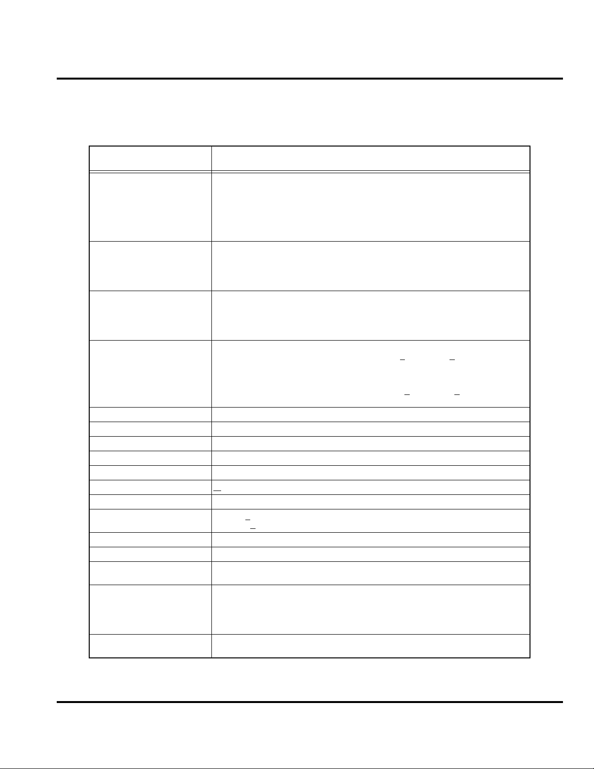
Specifications
Table 1. Specifications
Function Specification
Frequency Range EGSM TX: 880 - 915 MHz
Frequency Range DCS TX: 1710 to 1785 MHz
Frequency Range PCS TX: 1850 to 1910 MHz
Frequency Range UMTS TX: 1920 to 1980 MHz
Channel Spacing 200 kHz (GSM, DCS, PCS), 5 MHz UMTS
Channels 174 EGSM, 374 DCS, 274 PCS carriers with 8 channels per carrier, 11 UMTS
Duplex Spacing 45 MHz GSM, 95 MHz DCS, 80 MHz PCS, 190 MHz UMTS
Modulation GMSK AT BT = 0.3 (GSM, DCS, PCS), QPSK (UMTS)
Transmitter Phase Accuracy 5 degrees RMS, 20 Degrees peak
Frequency Error +
Input/Output Impedance 50 ohms (nominal)
Nominal Operating Voltage 3.6 Vdc +
Size 89 cc
Weight 118 g
Display Main Display: 262K color TFT, 320 x 240, 2.2”
Battery Life (840mAh)
Nominal Operating
Temperature Range
2
Frequency (MHz) = 890 + (0.2 × n) where: 0 ≤ n ≤ 124
Frequency (MHz) = 890 + (0.2 × (n – 1024)) where: 955 ≤ n ≤ 1023
RX: 925 – 960 MHz
Frequency (MHz) = 935 + (0.2 × n) where: 0 ≤ n ≤ 124
Frequency (MHz) = 935 + (0.2 × (n – 1024)) where: 955 ≤ n ≤ 1023
Frequency (MHz) = 1710.2 + (0.2 × (n – 512)) where: 512 ≤ n ≤ 885
RX: 1805.2 to 1879.8 MHz
Frequency (MHz) = 1805.2 + (0.2 × (n – 512)) where: 512 ≤ n ≤ 885
Frequency (MHz) = 1850.2 + (0.2 × (n – 512)) where: 512 ≤ n ≤ 810
RX: 1930 to 1990 MHz
Frequency (MHz) = 1930.2 + (0.2 × (n – 512)) where: 512 ≤ n ≤ 810
Frequency (MHz) = UARFCN1 ÷ 5, where: 9612 < UARFCN1 < 9888
UARFCN1 in increments of 25
RX: 2110 to 2170 MHz
Frequency (MHz) = UARFCN1 ÷ 5, where: 10562 < UARFCN1 < 10838
UARFCN1 in increments of 25
0.1ppm
10% (battery)
+4.4 Vdc +
CLI Display: 65K color STN, 96x80, 1”
GSM: Talk time: Up to 215 minutes
GSM: Standby time: Up to 220 to 260 hours
WCDMA Talk time: 131 hours
WCDMA Standby time: 227 hours
WCDMA Video talk time: Up to 90 minutes
-10º C to +55º C
10% (external connector)
6809497A15-A January 31, 2006 9
Page 10
Introduction V3x
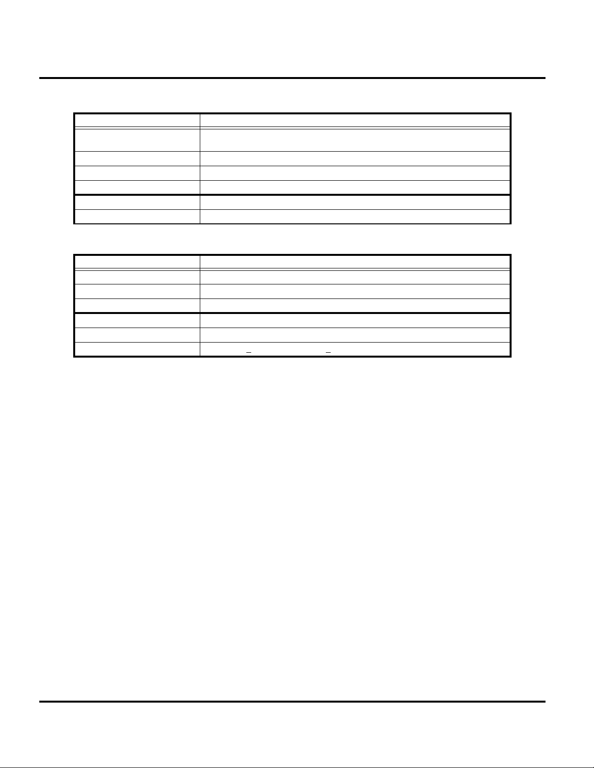
GSM System Functions Specification
Speech Coding Type Regular Pulse excitation / linear predictive coding with long term prediction
Bit Rate 13.0 kbps
RF Power Output 32 dBm nominal GSM, 28.5 dBm nominal DCS / PCS
Spurious Emissions -36 dBm from 0.1 to 1 GHz, -30 dBm from 1 to 4 GHz
Receive Sensitivity -102 dBm GSM, -102 dBm DCS / PCS
RX Bit Error Rate < 2%
UMTS System Functions Specification
Speech Coding Type Adaptive Multirate (AMR)
RF Power Output 21 dBm
Spurious Emissions -36 dBm from 0.1 to 1 GHz, -30 dBm from 1 to 4 GHz
Error Vector Magnitude < 17.5%
PN9 Bit Error Rate (VER) 0.1% @12.2K, -106.7 dBm
ACLR -33 dBm @+
(RPE LPC with LTP)
5 MHz, -43 dBm @+10 MHz
10 January 31, 2006 6809497A15-A
Page 11

Level 1 and 2 Service Manual Product Overview
Product Overview
Motorola V3x telephones deliver 3G features in a small and lightweight package.
These Global System for Mobile communications (GSM) General Packet Radio
Service (GPRS) Wireless Application Protocol (WAP)-enabled mobile phones
incorporate an icon based User Interface (UI) for easier operation, allows Short
Message Service (SMS) text messaging, Multi-media Messaging Services (MMS),
and includes Personal Information Manager (PIM) functionality. V3x is a tri-band
phones that allow roaming within the GSM 900 MHz, 1800 MHz Digital Cellular
System (DCS), and PCS 1900 MHz bands, in addition to the UMTS WCDMA 2100
MHz band.
V3x telephones have a clam form factor. They feature an externally viewable 96 x
80 65K color STN CLI display for caller identification with date/time, and an
internal 320 x 240 262K TFT color display located in the flip. The bottom part of
the clam (front housing) contains the keypad, transceiver printed circuit board
(PCB), microphone, flex connection, external accessory connector, smart button,
volume buttons, and voice button. The standard 840 mAh Lithium Ion (Li Ion)
battery fits behind a removable back cover and provides up to 220 minutes of talk
time and 200 hours of standby time in GSM mode. The battery provides up to 131
minutes of talk time, and up to 227 hours of standby time in WCDMA mode.
Features
The phone accepts 3V Subscriber Identity Module (SIM) cards that fit into the SIM
holder under the battery. The antenna is a fixed stub type antenna. Inexpensive
direct connection to a computer or handheld device through USB for data and fax
calls, and for synchronizing phonebook entries with Motorola mobile Phone Tools™
software, can be accomplished using the optional data cable and soft modem.
V3x telephones use advanced, self-contained, sealed, custom integrated circuits to
perform the complex functions required for WCDMA communication. Aside from
the space and weight advantage, microcircuits enhance basic reliability, simplify
maintenance, and provide a wide variety of operational functions.
Other features available in this family of telephones include:
• WCDMA 2100 MHz, GSM/GPRS 900/1800/1900 MHz
• Bluetooth Class 2
Physical
• Width 53mm
•Height 99mm
• Depth 19.8 mm
• Volume 89 cc
• Weight 118.0 grams
Audio
• AAC
• AAC+
•WAV
•MP3
• AAC+ Enhanced
•XMF
• RA v9
6809497A15-A January 31, 2006 11
Page 12

Product Overview V3x
•MIDI
Video
• MPEG4 Video clip playback
Display
• Main display 320 x 240 pixel 262k TFT
• CLI display 96 x 80 65k CSTN
Memory
• 64 MB internal RAM
• 32 MB internal ROM
• 64 MB internal ROM user memory
• Accepts removable TransFlash memory (16, 32 64, 128, 256 or 512MB)
modules
Imaging
• Primary camera resolution 2.0 MP
• Secondary camera resolution VGA
• Dedicated camera key
➧
➧
Wireless Access Protocol (WAP) 2.0 Compliancy
In the WAP environment, access to the Internet is initiated in Wireless Markup
Language (WML), which is derived from Hypertext Markup Language (HTML).
The request is passed to a WAP gateway, which retrieves the information from the
server in standard HTML (subsequently filtered to WML) or directly in WML if
available. The information is then passed to the mobile subscriber using the mobile
network.
Bitmap image data will download as text. If the image is larger than the screen,
only part of the image will display.
When the user receives a call while in browser mode, the browser will pause and
allow the user to resume after completing the call.
SIM Application ToolkitTM - Class 2
SIM Application Toolkit is a value-added service software product that allows GSM
operators to customize the services they offer their customers, from the occasional
user who requests sports news and traffic alerts, to a high call time business user
who receives stock alerts and checks flight times. Operators can now create their
own value-added services menu quickly and easily in the phone. The customized
menu will appear as the first menu and may be updated over-the-air with new
services when customers request them.
12 January 31, 2006 6809497A15-A
Page 13

Level 1 and 2 Service Manual Product Overview
Simplified Text Entry
There are three different ways to enter text using the phone keypad:
• iTAP predictive text entry. Press a key to enter a character, and a dynamic
dictionary uses this to build and display a set of word or name options. The
iTAP feature may not be available on the phone in all languages.
• Tap. Press a key to enter a character.
• Numeric. The keypad produces numeric characters only. For some text areas,
such as phone numbers, this is the only method available.
Caller Line Identification
Upon receipt of a call, the calling party’s phone number is compared to the
phonebook. If the number matches a phone book entry, that name will be displayed.
If there is no phone book entry, the incoming phone number will be displayed. If no
caller identification information is available, the Incoming Call message is
displayed.
The user must subscribe to a caller line identification service through their service
➧
provider.
Other Features
Detailed descriptions of these and the other features can be found in the appropriate
user’s guide listed in the “Related Publications” section toward the end of this
manual.
6809497A15-A January 31, 2006 13
Page 14
General Operation V3x
General Operation
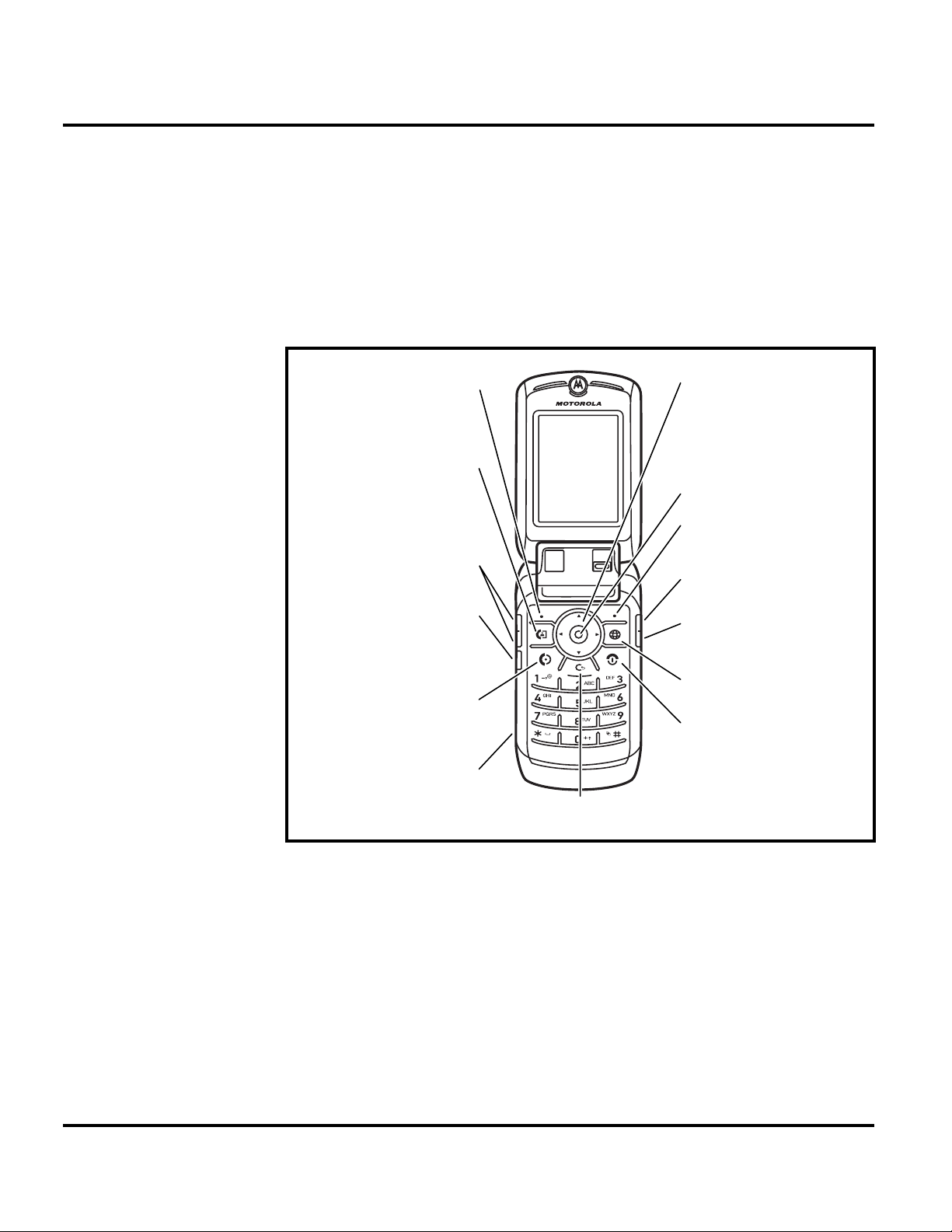
Controls, Indicators, and Input / Output (I/O) Connections
The V3x telephone’s controls are located on the sides of the phone and on the keypad.
Indicators, in the form of icons, are displayed on the LCD (see Figure 2). V3x phones
have an audible alert transducer on the top and I/O connectors, consisting of a
headset jack and an accessory port, located on the side and bottom of the phone See
Figure 1.
Left Soft Key
Make video
calls.
Volume Keys
Smart Key
Make &
answer calls.
Charge up or
go handsfree.
Scroll up,
down, left, or
right.
Select.
Right Soft
Key
Camera Key
Voice Dial
Key
Go online.
Turn on &
off, hang up,
exit menus.
Clear Key
050592o
Figure 1. Telephone Controls, indicators, and I/O Connections
Main Display
The main display provides a 262k color backlit display for easy readability in all
light conditions. The 320 x 240 display provides room for text, graphics, icons, and
prompts.
14 January 31, 2006 6809497A15-A
Page 15
Level 1 and 2 Service Manual General Operation
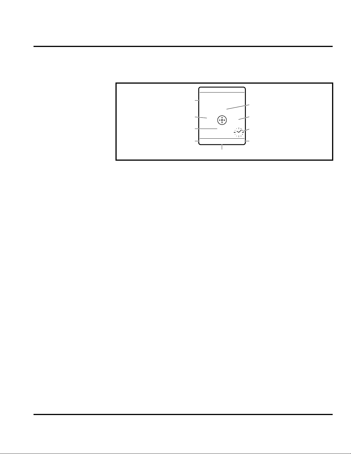
Display animation makes the phone’s menus move smoothly as the user scrolls up
and down
displayed on the LCD.
Turn animation off to conserve the battery. Figure 2 shows common icons
+49@ ] Ñr(yÉ
Service Provider
10/15/03
Date
Messages
e
Recent Calls
Phonebook
s
à
n
Browser
Clock
Alert Settings
Battery Function
Left Soft Key
Label
Figure 2. Icon Indicators
Whether a phone displays all indicators depends on the programming and services
➧
to which the user subscribes.
V3x telephones include up to 32 preset ring tones and vibrations that can be applied
to all alert events at the same time.
Pressing either volume key will mute the alert.
➧
STYLES
M
Menu Indicator
CAMERA
Right Soft Key
Label
Battery Gauge
The telephone displays a battery level indicator icon in the idle screen to indicate
the battery charge level. The gauge shows four levels: 100% (
33% (
Å), and Low Battery (Ä).
É), 66% (Ç),
031422o
Battery Removal
Removing the battery causes the phone to immediately shut down and any pending
work (for example, partially entered phone book entries or outgoing messages) is
lost.
To ensure proper memory retention, turn OFF the phone before removing the
➧
battery.
6809497A15-A January 31, 2006 15
Page 16

General Operation V3x
Operation
G
If the battery is removed while receiving a message, the message will be lost.
For detailed operating instructions, refer to the appropriate user’s guide listed in
“Related Publications” on page 45.
16 January 31, 2006 6809497A15-A
Page 17

1 and 2
Level 1 and 2 Service Manual Tools and Test Equipment
V3x
6809497A15-A
Tools and Test Equipment
Table 1 lists tools and test equipment recommended for disassembly and reassembly
of V3x telephones. Use either the listed items or equivalents.
Table 1. General Test Equipment and Tools
Motorola Part Number
RSX4043-A Torque Driver Used to remove and replace screws.
1
Description Application
—
See Table 7 Rapid Charger
0180386A82
0-00-00-30005
— Tweezers, Plastic
— Digital Multimeter, HP34401A
8102430Z04 GSM / DCS Test SIM Used to enable manual test mode.
1. To order in North America, contact Motorola Aftermarket and Accessories Division (AAD) at (800) 422-4210 or
FAX (800) 622-6210; Internationally, AAD can be reached by calling (847) 538-8023 or faxing (847) 576-3023.
2. Not available from Motorola. To order, contact Hewlett Packard at (800) 452-4844.
Torque Driver Bit T-3, T-5, T-6 Plus, Apex
440-6IP Torx Plus or equivalent
Antistatic Mat Kit (includes 66-80387A95
antistatic mat, 66-80334B36 ground
cord, and 42-80385A59 wrist band)
Disassembly tool, plastic with flat and
pointed ends (manual opening tool)
2
Used with torque driver.
Used to charge battery and to power
phone.
Provides protection from damage to
device caused by electrostatic discharge
(ESD).
Used during assembly/disassembly of
phone.
Used during assembly/disassembly of
phone.
Used to measure battery voltage.
6809497A15-A January 31, 2006 17
Page 18

Disassembly V3x
Disassembly
This section provides instructions for the disassembly of V3x telephones. Tools and
equipment used for the phone are listed in Table 1, preceding.
Many of the integrated devices used in these phones are vulnerable to damage from
G
G
Removing and Replacing the Battery Cover and Battery
E
ESD. Ensure adequate static protection is in place when handling, shipping, and
servicing the internal components of this phone.
Avoid stressing the plastic in any way to avoid damage to either the plastic or
internal components.
All batteries can cause property damage and/or bodily injury, such as burns, if a
conductive material, such as jewelry, keys, or beaded chains, touches exposed
terminals. The conductive material may complete an electrical circuit (short circuit)
and become very hot. Use care in handling any charged battery, particularly when
placing it inside a pocket, purse, or other container with metal objects.
1. Ensure the phone is turned off.
2. Press down on the battery latch and then slide the battery cover as shown in
Figure 1.
Battery Cover latch
Battery Cover
051209o
Figure 1. Removing the Battery Cover
3. Lift the battery cover away from the phone.
18 January 31, 2006 6809497A15-A
Page 19

Level 1 and 2 Service Manual Disassembly
1
2
4. Lift the bottom end of the battery first and then lift the battery out the phone.
(see Figure 2).
Battery
E
051210o
Figure 2. Removing the Battery
There is a danger of explosion if the Lithium Ion battery is replaced incorrectly.
Replace only with the same type of battery or equivalent as recommended by the
battery manufacturer. Dispose of used batteries according to the manufacturer’s
instructions.
5. To replace, align the battery with the battery compartment so the contacts on
the battery match the battery contacts in the phone.
6. Insert the battery, top end first, into the battery compartment and push down.
7. Insert the bottom edge of the battery housing into the base of the phone, then
slide the battery cover over the battery and snap it into place.
6809497A15-A January 31, 2006 19
Page 20

Disassembly V3x
Removing and Replacing the Subscriber Identity Module (SIM)
1. Remove the battery door and battery as described in the procedures.
2. Carefully slide the SIM out of the SIM holder.
SIM
SIM holder
060078o
Figure 3. Removing the SIM
3. To replace, slide the SIM into the holder, ensuring the notched corner of the
SIM aligns with the notch molded into the holder.
4. Replace the battery and battery cover as described in the procedures.
20 January 31, 2006 6809497A15-A
Page 21

Level 1 and 2 Service Manual Disassembly
Removing and Replacing the Antenna Cover
1. Remove the battery cover, battery and SIM, as described in the procedures.
2. Insert the disassembly tool under each side of the antenna cover to release the
antenna cover latches (see Figure 4).
Disassembly tool
Latch
Antenna cover
051212o
Figure 4. Removing the Antenna Cap
3. Carefully lift the antenna cover away from the phone.
4. To replace, align the antenna cover over the antenna.
5. Place the curved edge of the antenna cover onto the phone.
6. Carefully press the straight edge of the antenna cover into place until the
latches snap into place.
7. Insert the RF grommet fully into the opening on the antenna cover.
8. Reassemble the SIM, battery, and battery cover as described in the procedures.
6809497A15-A January 31, 2006 21
Page 22

Disassembly V3x
Removing and Replacing the Rear Housing
This product contains static-sensitive devices. Use anti-static handling procedures
G
to prevent electrostatic discharge (ESD) and component damage.
1. Remove the battery cover, battery, SIM, and antenna as described in the
procedures.
2. Using a Torx driver with a T-6 bit, remove the 6 screws along the sides of the
phone (see Figure 5).
Housing screw
Housing screw
Figure 5. Removing the Rear Housing Screws
Housing screws
Housing screws
051217o
22 January 31, 2006 6809497A15-A
Page 23

Level 1 and 2 Service Manual Disassembly
e
3. Carefully lift the rear housing away from the phone.
Disassembly tool
Rear housing fram
051218o
Figure 6. Removing the Rear Housing
4. Lower the rear housing onto the phone. Ensure the screw holes are aligned to
the transceiver PCB assembly.
5. Insert the 6 housing screws and tighten to a torque setting of 1.5 inch pounds
or 16 N/cm (Newton/centimeters). Do not over tighten.
6. Replace the SIM, battery, and battery cover as described in the procedures.
6809497A15-A January 31, 2006 23
Page 24

Disassembly V3x
Removing and Replacing the Transceiver Board Assembly
This product contains static-sensitive devices. Use anti-static handling procedures
G
G
to prevent ESD and component damage.
1. Remove the battery cover, battery, SIM, antenna, and rear housing as
described in the procedures..
The flexible printed cable (FPC) (flex) is easily damaged. Exercise extreme care when
handling.
2. Carefully work the flat end of the disassembly tool under the flex connector
and unseat the connector from its socket the transceiver board (see Figure 7).
ransceiver PCB Assembly
Disassembly tool
Flex connector
051219o
Figure 7. Disconnecting the Flex From the Transceiver Board
24 January 31, 2006 6809497A15-A
Page 25

Level 1 and 2 Service Manual Disassembly
3. Lift the transceiver board assembly and the keypad switchdome assembly out
of the front housing (see Figure 8).
Transceiver PC board
051222o
Figure 8. Removing the Transceiver Board Assembly
4. Use the T6 driver to remove the screw in the middle of the transceiver PC board
assembly (see Figure 9). Set the screw aside for re-use.
Transceiver PC board screw
051233o
Figure 9. Removing Transceiver PC Board Screw
6809497A15-A January 31, 2006 25
Page 26

Disassembly V3x
Removing and Replacing the Antenna
1. Remove the battery cover and battery, SIM, rear housing, and transceiver
board assembly as described in the procedures.
2. Unlatch the latches that secure the acoustic assembly to the transceiver PC
board.
Acoustic chamber latch
Acoustic chamber latch
051693o
Figure 10. Removing the Antenna Assembly
3. Lift the acoustic chamber assembly away from the transceiver PC board.
26 January 31, 2006 6809497A15-A
Page 27

Level 1 and 2 Service Manual Disassembly
4. Use the disassembly tool to pry the antenna out of the antenna assembly.
Disassembly tool
Acoustic chamber
Antenna
051694o
Figure 11. Removing the Antenna
5. To replace, insert the antenna into the acoustic chamber assembly.
6. Align the acoustic chamber assembly to the transceiver PC board and gently
press into position. Ensure the latches are secured to the PC board.
7. Replace the transceiver PC board assembly, rear housing, SIM, battery and
battery cover as described in the procedures.
6809497A15-A January 31, 2006 27
Page 28

Disassembly V3x
Removing and Replacing the Popple Dome PC Board
1. Remove the battery cover and battery, SIM, rear housing, transceiver board
assembly and antenna as described in the procedures.
2. Turn the Transceiver PC board assembly over and use the disassembly tool to
unseat the popple dome board flex connector (see Figure 12).
Transceiver PC boardPopple dome board
Popple dome flex connector
Disassembly tool
051235a
Figure 12. Removing the Popple dome FLEX Connector
3. Separate the popple dome board from the transceiver PC board assembly.
4. To replace, insert the popple dome flex connector squarely into its mating
connector on the transceiver board and press firmly until it snaps into place.
5. Turn the popple dome board over onto the transceiver PC board.
6. Insert and tighten the transceiver PC board screw with the T6 driver to a
torque setting of 13 N/cm. Do not overtighten.
7. Carefully place the transceiver board and the switchdome assembly into the
front housing.
8. Insert the display flex connector squarely into its mating connector on the
transceiver board and press firmly until it snaps into place.
9. Replace the rear housing, antenna, SIM, battery, and battery cover as
described in the procedures.
28 January 31, 2006 6809497A15-A
Page 29

Level 1 and 2 Service Manual Disassembly
Removing and Replacing the Keypad, Volume/Smart, and Voice Keys
1. Remove battery cover, battery, SIM, antenna, rear housing, and transceiver
board assembly as described in the procedures.
2. Use the plastic tweezers to lift the volume/smart keys out of their slot in the
front housing (see Figure 14).
Plastic tweezers
Volume/Smart Keys
Figure 13. Removing the Keypad, Volume/Smart, and Voice Buttons
051223o
6809497A15-A January 31, 2006 29
Page 30

Disassembly V3x
3. Use the plastic tweezers to lift the keypad assembly away from the front
housing (see Figure 14).
Plastic tweezers
Keypad
051225o
Figure 14. Removing the Keypad
4. To replace, insert the keypad into the front housing, ensuring the keys align
properly with the openings in the front housing.
5. Carefully set the keypad volume/smart buttons and voice button assembly onto
the metal switchdome assembly. Ensure the volume/smart key make contact
with the switchdome assembly on the transceiver board when installed.
6. Replace the transceiver board assembly, display flex connector, rear housing
assembly, antenna, SIM, battery, and battery cover as described in the
procedures.
30 January 31, 2006 6809497A15-A
Page 31

Level 1 and 2 Service Manual Disassembly
Removing and Replacing the Flip Assembly
1. Remove the battery cover, battery, SIM, antenna, rear housing, transceiver
board assembly, and keypad assembly as described in the procedures.
2. Carefully flex the base inner front housing downward to release the hinge
assembly from the front housing (see Figure 15).
Front
Housing
G
Hinge
Assembly
051226o
Figure 15. Removing the Flip Assembly
3. Carefully slide the display flex cable and connector through the housing
assembly. Avoid damage to the flex cable.
The flexible printed cable (FPC) (flex) is easily damaged. Exercise extreme care when
handling.
4. Lift the housing assembly away from the flip assembly. Be careful not to
damage the display flex cable.
5. To replace, carefully thread the display flex connector through the slot on the
keypad housing assembly. Avoid damaging the flex cable.
6. Flex the front housing slightly and insert the hinge assembly into the front
housing. Avoid damaging the flex cable and connector.
7. Replace the keypad assembly, transceiver board assembly, rear housing,
antenna, SIM, battery, and battery cover as described in the procedures.
6809497A15-A January 31, 2006 31
Page 32

Disassembly V3x
Removing and Replacing the Flip Cover
1. Remove the battery cover, battery, SIM, antenna, rear housing, transceiver
board assembly, keypad assembly and flip assembly as described in the
procedures.
2. Use the metal tweezers to remove the 2 flip screw covers at the top of the flip
assembly (see Figure 16).
Flip screw covers
051246o
Figure 16. Removing the Flip Cover Screws
3. Us e a T5 b it to re mo ve 2 fl ip scr ew s a t th e t op of t he fli p a sse mb ly loc at ed un de r
the screw covers. Set the screws aside for reuse unless they are damaged.
32 January 31, 2006 6809497A15-A
Page 33

Level 1 and 2 Service Manual Disassembly
4. Insert the tip of a thin bladed knife under the display lens starting under the
Motorola logo and pry it upward.
Knife
Flip Assembly
Display lens
051244o
Figure 17. Removing the Display Lens
5. Slide the pointed edge under the edge of the display lens to separate it from
the flip assembly and remove it from the flip assembly.
6. Use the T-5 driver to remove the 2 flip assembly screws at the bottom of the
flip assembly. Set the screws aside for re-use unless they are damaged.
Flip Assembly
Flip screw
Flip screw
052145o
Figure 18. Removing the Bottom Flip Screws
6809497A15-A January 31, 2006 33
Page 34

Disassembly V3x
7. Use the disassembly tool to remove the camera lens (see Figure 19).
disassembly tool
camera lens
Figure 19. Removing the Camera Lens
8. Use a T3 driver to remove the camera lens screw (see Figure 20).
Camera lens screw
Figure 20. Removing the Camera Lens Screw
060076o
o
34 January 31, 2006 6809497A15-A
Page 35

Level 1 and 2 Service Manual Disassembly
9. Insert the disassembly tool between the flip assembly and the flip housing to
release the 3 latches on each side of the flip assembly (see Figure 17).
Flip Housing Catch
Flip Housing
Catch
Flip Assembly
Flip Housing Catch
040958o
Figure 21. Removing the Display Lens
10. Carefully lift the flip cover away from the flip assembly. Avoid damaging the
display flex cable and connector.
11. To replace, align the flip cover with the flip assembly. Press the flip cover onto
the flip assembly until the 6 latches are fully engaged.
12. Insert and tighten the 4 flip screws with the T5 driver to a final torque setting
of 0.6 in.-lbs. Do not overtighten.
13. Remove the adhesive from the back of the new display lens and apply lens to
the flip housing.
14. Replace the flip assembly, keypad assembly, transceiver board assembly, rear
housing, antenna, SIM, battery, and battery cover as described in the
procedures.
6809497A15-A January 31, 2006 35
Page 36

Disassembly V3x
Removing and Replacing the Flip Display Assembly
1. Remove the battery cover, battery, SIM, antenna, rear housing, transceiver
board assembly, keypad assembly, flip assembly, and flip cover as described in
the procedures.
The flexible printed cable (FPC) (flex) is easily damaged. Exercise extreme care when
G
handling.
2. Use the disassembly tool to unseat the flip assembly flex connector from the
display assembly (see Figure 22).
Disassembly tool
Display Assembly
Figure 22. Removing the Flip Assembly Flex Connector
3. Move the flex connector away from the display assembly.
Flip Assembly
flex connector
051247o
36 January 31, 2006 6809497A15-A
Page 37

Level 1 and 2 Service Manual Disassembly
4. Use the disassembly tool to unseat the camera assembly flex connector from
the display module assembly (see Figure 23).
Disassembly tool
Camera assembly flex connector
G
040962o
Figure 23. Removing the Camera Assembly Flex Connector
The FPC (flex) is easily damaged. Exercise extreme care when handling.
6809497A15-A January 31, 2006 37
Page 38

Disassembly V3x
5. Use the pointed end of the disassembly tool to lift zero insertion force (ZIF)
latch that unlocks the ZIF connector socket (see Figure 24).
Speaker Flex ZIF Socket
Display Assembly
040963o
Figure 24. Removing the Display Assembly Flex Connector
6. Carefully disconnect the flex connector from the ZIF socket.
7. Carefully lift the display assembly out of the flip assembly (see Figure 25).
040964o
Figure 25. Removing the Display Assembly
38 January 31, 2006 6809497A15-A
Page 39

Level 1 and 2 Service Manual Disassembly
8. To replace, align the display assembly to the flip housing.
G
The FPC (flex) is easily damaged. Exercise extreme care when handling.
9. Lower the display assembly onto the flip housing.
10. Insert the speaker flex ZIF connector into the ZIF socket. Lock the ZIF
connector with the pointed end of the disassembly tool.
11. Carefully press the camera connector into its socket on the display assembly.
12. Carefully seat the display flex connector to the socket on the flip assembly.
13. Carefully align the flip flex assembly connector and seat it in it’s socket on the
the display assembly.
14. Carefully lower the display assembly onto the flip assembly. Be careful not to
damage the display flex or flex connector while reassembling the display lens
assembly.
15. Replace the flip assembly cover, flip assembly, keypad assembly, transceiver
board, rear housing, antenna, SIM, battery, and battery cover as described in
the procedures.
6809497A15-A January 31, 2006 39
Page 40

Subscriber Identity Module (SIM) and Identification V3x
Subscriber Identity Module (SIM) and Identification
SIM Card
A SIM is required to access the existing local GSM network, or remote networks
when traveling (if a roaming agreement has been made with the provider).
The SIM contains:
• All the data necessary to access GSM services
• The ability to store user information such as phone numbers
• All information required by the network provider to provide access to the
network
Personality Transfer
A personality transfer is required when a phone is express exchanged or when the
main board is replaced. Personality transfers reproduce the customer's personalized
details such as menu, and stored memory, such as phonebooks, or program the
customer’s phone with basic user information such as language selection. V3x
telephones use mobile PhoneTools® synchronization software to effect a personality
transfer.
Identification
Each Motorola GSM phone is labeled with a several identifying numbers. The
following section describes the current identifying labels.
Mechanical Serial Number (MSN)
The Mechanical Serial Number (MSN) is an individual unit identity number and
remains with the unit throughout its life.
The MSN can be used to log and track a phone on Motorola's Service Center
Database.
The MSN is divided into 4 sections as shown in Figure 26.
MSN 10 Digits
3 Digits 1 Digit 2 Digits 4 Digits
APC DC DC SNR
Account Product Code
e.g., StarTAC Phone130
TM
Figure 26. MSN Label Breakdown
Distribution Center
e.g., Easter Inch
Date Code: Year and
Month of Shipment
Phone's individual serial
number
000807b
40 January 31, 2006 6809497A15-A
Page 41

Level 1 and 2 Service Manual Subscriber Identity Module (SIM) and Identification
International Mobile Station Equipment Identity (IMEI)
The International Mobile station Equipment Identity (IMEI) number is an
individual number unique to the PCB and stored within the phone's memory.
The IMEI uniquely identifies an individual mobile station provides a way to control
access to GSM networks based on mobile station types or individual phones. The
full IMEI structure is listed in Table 2.
Table 2. IMEI Number Breakdown
TAC Serial Number Check Digit
NNXXXXXX ZZZZZZ A
Where:
TAC Type Allocation Code, formerly known as Type Approval Code
NN Reporting body identifier
XXXXXX Type identifier
ZZZZZZ Individual unit serial number
A Phase 1 = 0.
Phase 2 = check digit defined as a function of all other IMEI digits
Other label number configurations present are:
• TRANSCEIVER NUMBER: Identifies the product type, usually the SWF
number. (for example, V100).
• PACKAGE NUMBER: Identifies the equipment type, mode, and language in
which the product is shipped.
6809497A15-A January 31, 2006 41
Page 42

Troubleshooting V3x
Troubleshooting
Table 3. Level 1 and 2 Troubleshooting Chart
SYMPTOM PROBABLE CAUSE VERIFICATION AND REMEDY
1. Telephone will not turn on or stay on. a) Battery either discharged or
2. Telephone exhibits poor reception or
erratic operation such as calls frequently
dropping or weak or distorted audio.
3. Display is erratic, or provides partial or
no display.
4. Incoming call alert transducer audio
distorted or volume is too low.
defective.
b) Battery connectors open or
misaligned.
c) Transceiver board assembly
defective.
d) keyboard assembly failure. Replace the keyboard assembly. Temporarily
a) Antenna assembly defective. Check to make sure that the antenna pin is
b) Transceiver board assembly
defective.
a) Transceiver board connections
faulty.
b) Flip assembly defective. Temporarily replace the flip assembly with a
c) Transceiver board assembly
defective.
Faulty transceiver board assembly. Replace the transceiver board assembly (refer
Measure battery voltage across a 50 ohm (>1
Watt) load. If the battery voltage is <3.25 Vdc,
recharge the battery using the appropriate
battery charger. If the battery will not recharge,
replace the battery. If battery is not at fault,
proceed to b.
Visually inspect the battery connectors on both
the battery and the telephone. Realign and, if
necessary, either replace the battery or refer to
a Level 3 Service Center for battery connector
replacement. If battery connectors are not at
fault, proceed to c.
Remove the transceiver board assembly.
Substitute a known good assembly and
temporarily reassemble. Press and hold the
PWR button; if the phone turns on and stays on,
disconnect the dc power source and reassemble
with the new transceiver board assembly. Verify
that the fault has been cleared. If the fault has
not been cleared then proceed to d.
connect a +3.6 Vdc supply to the battery
connectors. Press and hold the PWR button. If
the phone turns on and stays on, disconnect the
dc power source and reassemble with the new
keyboard assembly.
properly connected to the transceiver board
assembly. If connected properly, substitute a
known good antenna. If the fault is still present,
proceed to b.
Replace the transceiver board assembly (refer
to 1c). Verify that the fault has been cleared and
reassemble the unit with the new transceiver
board assembly.
Remove rear chassis assembly from the phone,
check general condition of FPC (flex). If the flex
is good, check that the flex connector is fully
pressed down. If not, check connector to
transceiver board connections. If faulty
connector, replace the transceiver board
assembly. If connector is not at fault, proceed to
b.
known good assembly. If fault has been cleared,
reassemble with the new flip assembly. If fault
not cleared, proceed to c.
Replace the transceiver board assembly (refer
to 1c). Verify that the fault has been cleared and
reassemble the unit with the new transceiver
board assembly.
to 1c). Verify that the fault has been cleared and
reassemble with the new transceiver board
assembly.
42 January 31, 2006 6809497A15-A
Page 43

Level 1 and 2 Service Manual Troubleshooting
Table 3. Level 1 and 2 Troubleshooting Chart (Continued)
SYMPTOM PROBABLE CAUSE VERIFICATION AND REMEDY
5. Telephone transmit audio is weak
(usually indicated by called parties
complaining of difficulty in hearing voice).
6. Receive audio from earpiece speaker is
weak or distorted.
7. Telephone will not recognize or accept
SIM.
8. Phone does not sense when flip is
opened or closed (usually indicated by
inability to answer incoming calls by
opening the flip, or inability to make
outgoing calls).
a) Microphone connections to the
transceiver board assembly defective.
b) Microphone defective. Gain access to microphone. Disconnect and
c) Transceiver board assembly
defective.
a) Connections to or from transceiver
board assembly defective.
b) Flip assembly defective. Temporarily replace the flip assembly with a
c) Antenna assembly defective. Check that the antenna is installed correctly. If
d) Transceiver board assembly
defective.
a) SIM defective. Check the SIM contacts for dirt. Clean if
b) Flip assembly defective. Temporarily replace the flip assembly with a
c) Transceiver board assembly
defective.
a) Flip assembly defective. Temporarily replace the flip assembly with a
b) Transceiver board assembly
defective.
Gain access to the microphone as described in
the procedures. Check connections. If connector
is faulty proceed to c; if the connector is not at
fault, proceed to b.
substitute a known good microphone. Place a
call and verify improvement in transmit signal as
heard by called party. If good, reassemble with
new microphone. If microphone is not at fault,
reinstall original microphone and proceed to c.
Replace the transceiver board assembly (refer
to 1c). Verify that the fault has been cleared and
reassemble with the new transceiver board
assembly.
Gain access to the transceiver board assembly
as described in the procedures. Check flex and
the flex connector from the flip assembly to the
transceiver board assembly. If flex is at fault,
replace flip assembly. If flex connector is at fault,
proceed to d. If connection is not at fault,
proceed to b.
known good assembly. If fault has been cleared,
reassemble with the new flip assembly. If fault
not cleared, proceed to c.
the antenna is installed correctly, substitute a
known good antenna assembly. If this does not
clear the fault, reinstall the original antenna
assembly and proceed to d.
Replace the transceiver board assembly (refer
to 1c). Verify that the fault has been cleared and
reassemble with the new transceiver board
assembly.
necessary and check if fault has been cleared. If
the contacts are clean, insert a known good SIM
into the telephone. Power up the phone and
confirm that the SIM has been accepted. If the
fault no longer exists, replace the defective SIM.
If the SIM is not at fault, proceed to b.
known good assembly. If fault has been cleared,
reassemble with the new flip assembly. If fault
not cleared, proceed to c.
Replace the transceiver board assembly (refer
to 1c). Verify that the fault has been cleared and
reassemble with the new transceiver board
assembly.
known good assembly. If fault has been cleared,
reassemble with the new flip assembly. If fault
not cleared, proceed to b.
Replace the transceiver board assembly (refer
to 1c). Verify that the fault has been cleared and
reassemble with the new transceiver board
assembly.
6809497A15-A January 31, 2006 43
Page 44

Troubleshooting V3x
Table 3. Level 1 and 2 Troubleshooting Chart (Continued)
SYMPTOM PROBABLE CAUSE VERIFICATION AND REMEDY
9. Vibrator feature not functioning. Transceiver board assembly defective. Replace the transceiver board assembly (refer
10. Internal Charger not working. Faulty charger circuit on transceiver
11. Real Time Clock resetting when
standard battery is removed.
12. No or weak audio when using headset. a) Headset plug not fully pushed into
board assembly.
Lithium button cell in the display board
may be depleted.
the jack socket.
b) Faulty jack socket on transceiver
board assembly.
to 1c). Verify that the fault has been cleared and
reassemble with the new transceiver board
assembly.
Test a selection of batteries in the rear pocket of
the desktop charger. Check LED display for the
charging indications. If the batteries charge
properly, then the internal charger is at fault.
Replace the transceiver board assembly (refer
to 1c). Verify that the fault has been cleared and
reassemble with the new transceiver board
assembly.
Refer service to a Level 3 service center for
replacement.
Ensure the headset plug is fully seated in the
jack socket. If fault not cleared, proceed to b.
Replace the transceiver board assembly (refer
to 1c). Verify that the fault has been cleared and
reassemble with the new transceiver board
assembly.
Programming: Software Upgrade and Flexing
Contact your local technical support engineer for information about equipment and
procedures for flashing and flexing.
44 January 31, 2006 6809497A15-A
Page 45

Level 1 and 2 Service Manual Part Numbers
Part Numbers
The following charts are provided as a reference for the parts associated with
V3x telephones.
Related Publications
Motorola V3x User’s Guide, English 68XXXXX108
6809497A15-A January 31, 2006 45
Page 46

Part Numbers V3x
Exploded View Diagram
23
1
2
10
8
12
11
15
20
21
22
26
25
9
3
5
4
7
13
14
16
17
18
29
27
28
30
31
32
33
34
35
36
37
040967o
Figure 27. Exploded View Diagram
46 January 31, 2006 6809497A15-A
Page 47

Level 1 and 2 Service Manual Part Numbers
Exploded View Parts List
Table 4. Exploded View Parts List
Item
Number
1 6171885B01 LENS, 2MP 20 0171343C01 MODULE, VGA
2 4885102C24 FLASH, CAMERA
3 6188777Y01 LENS, CLI 22 6171865B01 LENS, VGA
4 0171425C01 HOUSING, FLIP OUTER 23 6188778Y01 LENS, MAIN DISPLAY
5 3371139D01 ESCUTCHEON, FLIP
6 1171902B01 GASKET, CLI
7 0171102C01 MODULE, DISPLAY
8 0171456C01 FLEX, HINGE
9 5571967B01 CAM, HINGE
10 3871407C01 ADJUST, MACRO
11 0171347C01 MODULE, 2MP
12 3271688B01 GASKET, 2MP 31 0171107C01 SHIELD, SPACER ASSY
13 5988515L01 MAGNET 32 SLG4932AA PCB, TRANSCEIVER, ASSY
14 0171325C01 SPEAKER, EARPIECE ASSY
15 0188755Y01 HOUSING, FLIP INNER
16 1371698B01 MESH, ACOUSTIC 35 SNN5781A BATTERY, MAIN, SC5
17 0387726M02 SCREW, FLIP (4X)
18
19 3371697B02 ESCUTCHEON, EARPIECE
Part Number Description
3271689B02
3271689B01
BUMPER, FLIP (left)
Bumper, flip (right)
Item
Number
21 3271688B02 GASKET, VGA
24 0387726M02 SCREW, FLIP
25 0188747Y01
26 3971966B01 CONTACT, KNUCKLE
27 3888722Y01 KEYPAD, MAIN
28 3871943B01
29 3871942B01 BUTTONS, SIDE, CAM / VA
30 0171646C01 FLEX, POPPLE DOME / EL
33 0188746Y01
34 0387791L07 SCREW, BASE (6X)
36 1571931B01 COVER, BATTERY SC5
37 1571951B01
Part Number Description
HOUSING, BASE INNER
ASSY
BUTTONS, SIDE, UP / DN /
SMART
HOUSING, BASE OUTER
ASSY
HOUSING, LOWER ANTENNA
CAP
There is a danger of explosion if the Lithium Ion battery pack is replaced incorrectly.
Replace only with the same type of battery or equivalent as recommended by the
E
battery manufacturer. Dispose of used batteries according to the manufacturer’s
instructions.
To order parts use the following Link:
https://wissc.motorola.com/wissc_root/main/BrowserOK.html
(Password is Required)
For information on ordering parts contact EMEA at +49 461 803 1404.
6809497A15-A January 31, 2006 47
Page 48

Part Numbers V3x
48 January 31, 2006 6809497A15-A
Page 49

1 and 2
Index
Level 1 and 2 Service Manual Index
V3x
6809497A15-A
IMEI
A
alert settings 15
antenna cap, removing and replacing
antenna, removing and replacing
26
21
41
indicators
service indicator (status light)
Introduction
5
14
B
battery
function
gauge
removing
battery cover
removing
15
15
18
18
C
caller ID 13
Canadian Interference-Causing Equipment regulations
changes
product
conventions
copyrights
computer software
5
7
6
D
disassembly 18
display
14
E
exploded view diagram 46
exploded view parts list
47
F
FCC rules 5
features
caller ID
SIM Toolkit
text entry
Wireless Access Protocol (WAP)
features, product
flip assembly, removing and replacing
flip cover, removing and replacing
flip display assembly, removing and replacing
13
12
13
12
11
31
32
36
I
identification 40
international mobile station equipment identity
mechanical serial number
product
5
40
41
L
liquid crystal display (LCD) 14
M
MSN 40
N
names
product
5
5
O
operation
controls, indicators, and I/O
operation, general
overview, product
P
parts 45
exploded view diagram
exploded view parts list
product
changes
identification
names
publications, related
5
5
R
rear housing
removing
regulatory agency compliance
related publications
removing
antenna
antenna cap
battery
battery cover
flip assembly
flip cover
flip display assembly
rear housing
SIM
transceiver board assembly
22
26
15, 18
32
20
14
14
11
46
47
5
45
5
45
21
18
31
36
22
24
6809497A15-A January 31, 2006 Index-1
Page 50

Index V3x
volume/smart buttons 29
replacement parts
contact information
replacing
antenna
antenna cap
battery
flip assembly
flip cover
flip display assembly
rear housing
SIM
transceiver board assembly
volume/smart buttons
26
18
32
20
8
21
31
36
22
29
S
serial number
mechanical
service manual
about
revisions
scope
service policy
customer support
out of box failure
product support
service procedure
ordering replacement parts
shut down
upon battery removal
SIM Application Toolkit
SIM card
personality transfer
replacing
SIM, removing and replacing
specifications
support
customer
product
40
6
7
6
7
7
7
7
15
12
40
40
20
9
7
7
20
24
8
W
warranty service 7
wireless access protocol (WAP)
12
T
text entry 13
tools and test equipment
transceiver board assembly, removing and replacing
troubleshooting
42
17
24
V
volume/smart buttons, removing and replacing 29
Index-2 January 31, 2006 6809497A15-A
Page 51

Page 52

MOTOROLA and the Stylized M Logo are registered in the US Patent & Trademark Office.
The Bluetooth trademarks are owned by their proprietor and used by Motorola, Inc. under license.
All other product or service names are the property of their respective owners.® Reg. U.S. Pat. & Tm. Off.
© 2005 Motorola, Inc.
All rights reserved.
Mobile Devices Business,
Sawgrass International Concourse
789 International Parkway, Mailstop S2C
Sunrise, FL 33325-6222
 Loading...