

Page 1
MC1000 with Windows CE 4.2
User Guide
Page 2

Page 3

MC1000 with Windows CE 4.2
User Guide
72E-69840-02
Rev. A
August 2007
Page 4

ii MC1000 with Windows CE 4.2 User Guide
© 2007 by Motorola, Inc. All rights reserved.
No part of this publication may be reproduced or used in any form, or by any electrical or mechanical means,
without permission in writing from Motorola. This includes electronic or mechanical means, such as
photocopying, recording, or information storage and retrieval systems. The material in this manual is subject to
change without notice.
The software is provided strictly on an “as i s” basis. All sof twar e, including firmware, furnished to the user is on
a licensed basis. Motorola grants to the user a non-transferab le and non-exclusive license to use each
software or firmware program delivered hereunder (licensed program). Except as noted below, such license
may not be assigned, sublicensed, or otherwise transferred by the user without prior written consent of
Motorola. No right to copy a licensed program in whole or in part is granted, except as permitted unde r
copyright law. The user shall not modify, merge, or incorporate any form or portion of a licensed program with
other program material, create a derivative work from a licensed program, or use a licensed program in a
network without written permission from Motorola. The user agrees to maintain Motorola’s copyright notice on
the licensed programs delivered hereunder, and to include the same on any authorized copies it makes, in
whole or in part. The user agrees not to deco mpile, disassemble, decode, or reverse engineer any licensed
program delivered to the user or any portion thereof.
Motorola reserves the right to make changes to any software or product to improve reliability, function, or
design.
Motorola does not assume any product liability arising out of, or in connection with, the application or use of
any product, circuit, or application described herein.
No license is granted, either expressly or by implication, estoppel, or otherwise under any Motorola, Inc.,
intellectual property rights. An implied license only exists for equipment, circuits, and subsystems contained in
Motorola products.
MOTOROLA and the Stylized M Logo and Symbol and the Symbol logo are registered in the US Patent &
Trademark Office. Bluetooth is a registered trademark of Bluetooth SIG. Microsoft, Windows and ActiveSync
are either registered trademarks or trademarks of Microsoft Corporation. All other product or service names
are the property of their respective owners.
Motorola, Inc.
One Motorola Plaza
Holtsville, New York 11742-1300
http://www.symbol.com
Patents
This product is covered by one or more of the patents listed on the website: www.symbol.com/patents
Page 5
Revision History
Changes to the original manual are listed below:
Change Date Description
-01 Rev A 04/07/05 Initial release.
-02 Rev A 08/31/07 Re-branding.
iii
Page 6

iv MC1000 with Windows CE 4.2 User Guide
Page 7

Table of Contents
Patents.................................................................................................................................................. ii
Revision History.................................................................................................................................... iii
About This Guide
Introduction........................................................................................................................................... vii
Documentation Set vii
Features................................................................................................................................................ vii
Chapter Descriptions............................................................................................................................ viii
Notational Conventions......................................................................................................................... ix
Related Documents and Software........................................................................................................ ix
Service Information............................................................................................................................... x
Chapter 1: Getting Started
Introduction .......................................................................................................................................... 1-1
Accessories ......................................................................................................................................... 1-1
Parts .................................................................................................................................................... 1-3
Getting Started ..................................................................................................................................... 1-3
Main Battery Installation ................................................................................................................. 1-3
Li-ion Battery Installation ................................................................................................................ 1-4
AAA Battery Installation ................................................................................................................. 1-5
Battery Charging .................................................................................................................................. 1-5
Starting the Mobile Computer .............................................................................................................. 1-6
Waking the Mobile Computer .............................................................................................................. 1-7
Li-ion Battery Removal ........................................................................................................................ 1-7
AAA Batteries Removal ....................................................................................................................... 1-8
Spare Battery Charging ....................................................................................................................... 1-8
SD Memory Card ................................................................................................................................. 1-8
Wrist Strap ........................................................................................................................................... 1-10
Chapter 2: Operating the MC1000
Introduction .......................................................................................................................................... 2-1
Page 8

vi MC1000 with Windows CE 4.2 User Guide
Power Button ....................................................................................................................................... 2-1
Keypad ................................................................................................................................................. 2-1
Using the Keypad to Navigate Applications ................................................................................... 2-4
Key Combinations .................................................................................................................... 2-4
Selecting Items ........................................................................................................................ 2-4
Adjusting the Beeper Volume .............................................................................................................. 2-5
Adjusting the Screen Contrast ............................................................................................................. 2-5
Start Button .................................................................................................................................... 2-8
Entering Information ............................................................................................................................ 2-8
Entering Information Using the Keypad ......................................................................................... 2-8
Entering Data via the Bar Code Scanner ....................................................................................... 2-9
Scan Indicator LED .................................................................................................................. 2-10
Scanning Considerations ............................................................................................................... 2-10
Laser Decode Ranges ................................................................................................................... 2-11
Resetting the Mobile Computer ........................................................................................................... 2-12
Performing a Warm Boot ............................................................................................................... 2-12
Performing a Cold Boot .................................................................................................................. 2-12
Waking the Mobile Computer .............................................................................................................. 2-13
File System Directory Structure ........................................................................................................... 2-13
Chapter 3: Accessories
Introduction .......................................................................................................................................... 3-1
Cradles ........................................................................................................................................... 3-1
Cables ............................................................................................................................................ 3-1
Single Slot Serial/USB Cradle ............................................................................................................. 3-2
Battery Charging ............................................................................................................................ 3-3
Cable Connection .......................................................................................................................... 3-6
Battery Charging ............................................................................................................................ 3-7
Chapter 4: Maintenance & Troubleshooting
Introduction .......................................................................................................................................... 4-1
Maintaining the Mobile Computer ........................................................................................................ 4-1
Troubleshooting ................................................................................................................................... 4-2
Mobile Computer ............................................................................................................................ 4-2
Single Slot Serial/USB Cradle ........................................................................................................ 4-4
Four Slot USB Cradle .................................................................................................................... 4-5
Cables ............................................................................................................................................ 4-6
Appendix A: Technical Specifications
Mobile Computer Technical Specifications .......................................................................................... A-1
Glossary
Index
Page 9

About This Guide
Introduction
This guide provides information about using the MC1000 mobile computer and accessories.
NOTE Screens and windows pictured in this guide are samples and can differ from actual screens.
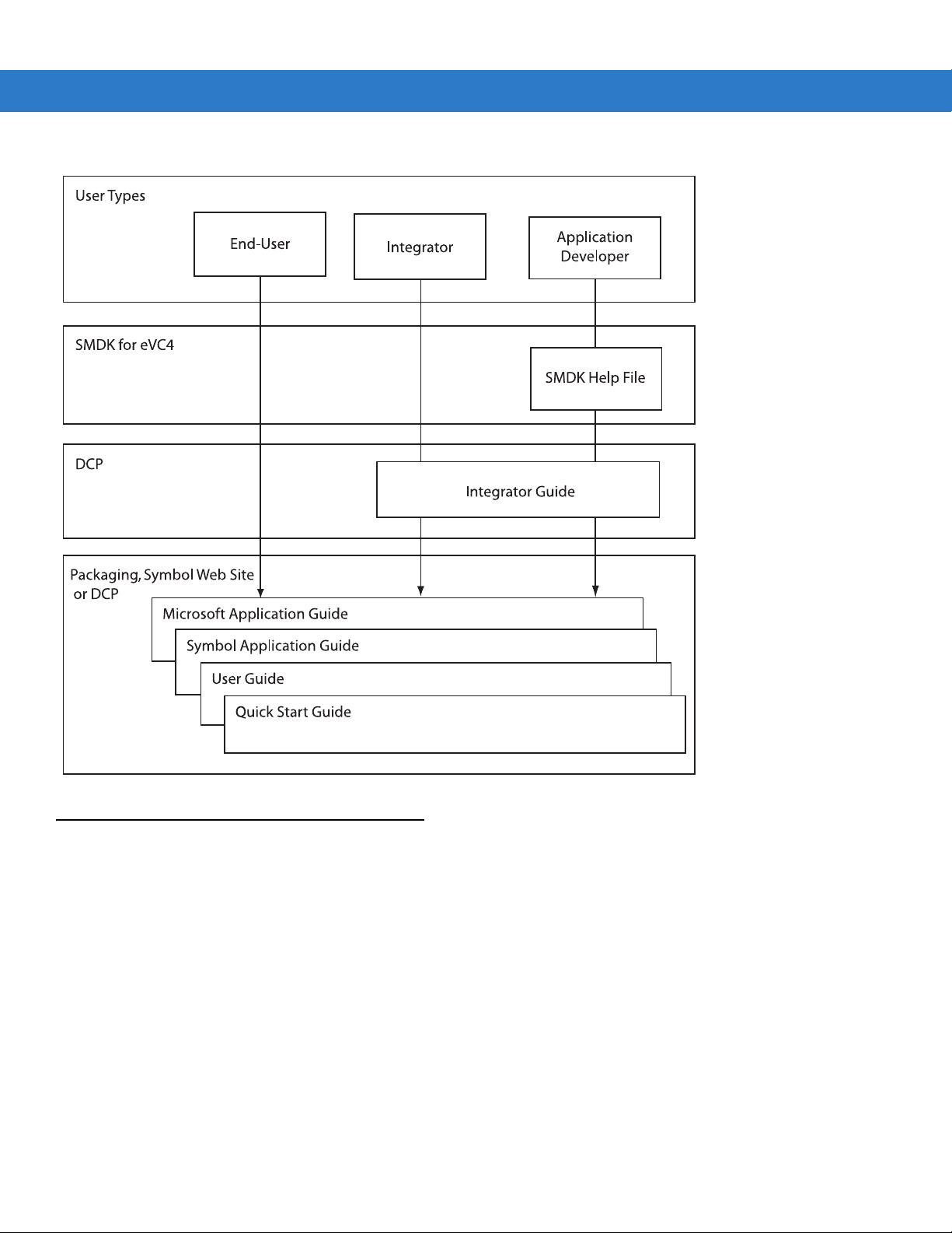
Documentation Set
The documentation set for the MC1000 is divided into guides that provide in formation for specific user needs.
•
Microsoft Application Guide - describes how to use Microsoft developed applications.
•
Symbol Application Guide - describes how to use Symbol developed applications.
•
MC1000 User Guide - describes how to use the MC1000 mobile computer.
•
MC1000 Integrator Guide - describes how to set up the MC1000 mobile computer and it’s accessories.
Features
The MC1000 includes the following features:
•
SMDK Help File - provides API information for writing applications.
•
Operating System: Microsoft Windows CE .NET 4.2 Core
•
Memory Configuration: 32 MB RAM/32 MB Flash
•
Screen: monochrome 240 x 240 pixel, 2.2” diagonal, non-touch
•
Expansion: User accessible Secure Digital (SD) slot
•
Keypads: 21-key keypad
•
Data Capture: 1-dimensional bar code laser scanning.
Page 10
viii MC1000 with Windows CE 4.2 User Guide
Chapter Descriptions
Topics covered in this guide are as follows:
•
Chapter 1, Getting Started, provides information on getting the mobile computer up and running for the first
time.
•
Chapter 2, Operating the MC1000, explains how to use the mobile computer. This includes instructions for
powering on and resetting the mobile computer, entering and capturing data.
•
Chapter 3, Accessories, describes the accessories available for the mobile computer and how to use the
accessories with the mobile computer.
•
Chapter 4, Maintenance & Troubleshooting, includes instructions on cleaning and storing the mobile
computer, and provides troubleshooting solutions for potential problems during mobile computer operation.
•
Appendix A, Technical Specifications, includes a table listing the technical specifications for the mobile
computer.
Page 11

Notational Conventions
The following conventions are used in this document:
•
“Mobile computer” refers to the MC1000 mobile computer.
•
Italics are used to highlight the following:
• Chapters and sections in this and related documents
• Dialog box, window and screen names
• Drop-down list and list box names
• Check box and radio button names
• Icons on a screen.
•
Bold text is used to highlight the following:
• Key names on a keypad
• Button names on a screen.
•
Bullets (•) indicate:
• Action items
• Lists of alternatives
• Lists of required steps that are not nece ssarily sequential.
About This Guide ix
•
Sequential lists (e.g., those that describe step-by-s te p pr oc ed ur e s) ap pe a r as nu m be re d lists.
Related Documents and Software
The following documents provide more information about the MC1000 mobile computers.
•
MC1000 Quick Start Guide (poster), p/n 72-69838-xx
•
MC1000 Licensing, Patent and Regulatory In fo rm at ion , p/n 72-69839-xx
•
MC1000 with Windows CE 4.2 Integrator Guide, p/n 72E-69841-xx
•
Symbol Applications Guide for Symbol Devices, p/n 72-68901-xx
•
Microsoft Applications Guide for Symbol Devices, p/n 72-68197-xx
•
Symbol Mobility Developer Kit (SMDK) Help File, p/n 72E-38880-02
•
Symbol Mobility Developer Kit for eMbedded Visual C++ v4.0 (SMDK for eVC4) , available at:
http://www.symbol.com/MC1000
•
Device Configuration Package for MC1000 (DCP for MC1000), available at:
http://www.symbol.com/MC1000.
•
ActiveSync software, available at: http://www.microsoft.com.
For the latest version of this guide and all guides, go to: http://www.symbol.com/manuals.
Page 12

x MC1000 with Windows CE 4.2 User Guide
Service Information
If you have a problem with your equipment, contact Motorola Enterprise Mobility support for your region. Contact
information is available at: http://www.symbol.com/contactsupport
When contacting Enterprise Mobility support, please have the following information available:
•
Serial number of the unit
•
Model number or product name
•
Software type and version number
Motorola responds to calls by email, telephone or fax within the time limits set forth in support agreements.
If your problem cannot be solved by Motorola Enterprise Mobility Support, you may need to return your equipment
for servicing and will be given specific directions. Motorola is not responsible for any damages incurred during
shipment if the approved shipping container is not used. Shipping the units improperly can possibly void the
warranty.
If you purchased your Enterprise Mobility business product from a Motorola business partner, contact that business
partner for support.
.
Page 13

Chapter 1 Getting Started
Introduction
This chapter describes the mobile computer’s physical characteristics, how to install and charge the bat terie s,
remove and replace the handstrap, and start the mobile computer for the first time.
Unpacking the Mobile Computer
Carefully remove all protective material from around the mobile computer and save the shipping cont ainer for later
storage and shipping. Verify that the equipment listed below is included:
•
MC1000 mobile computer
•
Wrist strap
•
Regulatory Guide
•
Quick Start Guide.
Inspect the equipment for damage. If any equipment is missing or damaged, contact Motorola Enterprise Mobility
support immediately. See page x for contact information.
Accessories
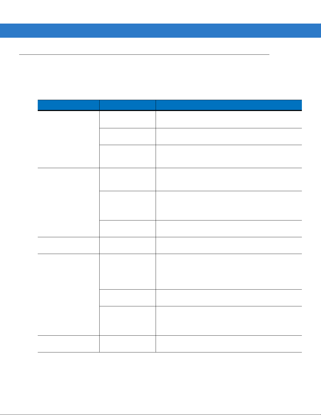
Table 1-1 lists the accessories available for the MC1000:
Table 1-1
Single Slot Serial/USB Cradle Charges the mobile computer main battery and a spare battery, and
Four Slot USB Cradle Charges up to four mobile computers and synchronizes the mobile
Power Supply Country-specific and accessory specific power supply and line cord, plugs
MC1000 Accessories
Accessory Description
synchronizes the mobile computer with a host computer through a serial or
USB connection.
computers with a host computer through a USB connection.
into the pigtail connector.
Page 14

1 - 2 MC1000 with Windows CE 4.2 User Guide
Table 1-1
USB Client Charge Cable Provides USB client communication capabilities and charges the mobile
RS232 Charge Cable Provides RS232 communication capabilities and charges the mobile
Single Slot Cradle RS232 Cable Provides serial host communication capabilities.
Single Slot Cradle USB Cable Provides USB connection to a host computer.
Four Slot Cradle USB Cable Provides internal USB hub for connection to host computer.
Handstrap Provides additional support when holding the mobile computer.
Li-ion Rechargeable Battery Spare 1800 mAh battery.
Modem Module Connects to the Single Slot Serial/USB cradle to allow the cradle to be used
Modem Cable Connects the Modem Module to the Single Slot Serial/USB cradle.
Symbol Mobility Developer Kit for
eMbedded Visual C++ v4.0 (SMDK
for eVC4)
MC1000 Accessories (Continued)
Accessory Description
computer.
computer.
as a modem cradle.
A development tool used to create native C and C++ applications for all
Symbol mobile computers running the Microsoft Windows Mobile 2003
Software for Pocket PCs operating system. Available at:
http://www.symbol.com/MC1000
Platform SDK Used in conjunction with the SMDK for eVC4 to create Windows CE
applications for the MC1000 mobile computer. Available at:
http://www.symbol.com/support.
Device Configuration Package
(DCP) for MC1000
A development tool used to create and download hex images that represent
flash partitions to the mobile computer. Available at:
http://www.symbol.com/MC1000.
Page 15
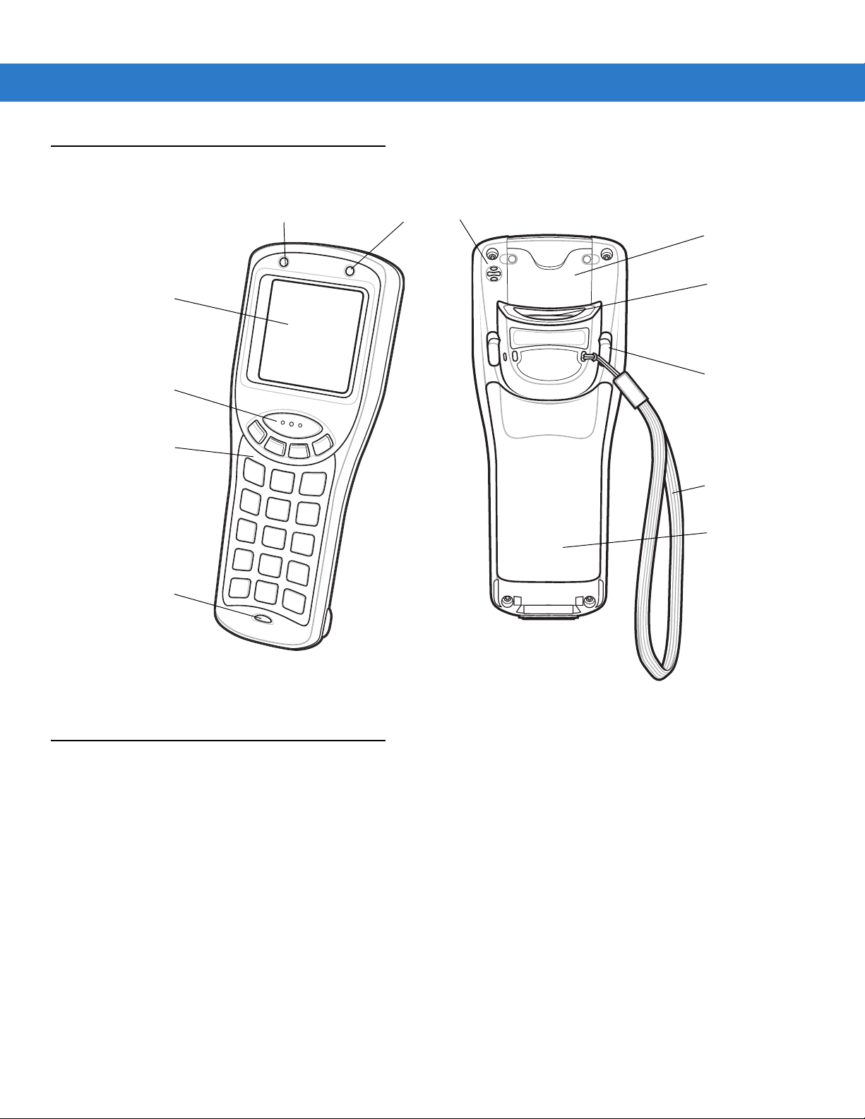
Parts
Scan LED
Scan Window
Battery Door
Battery Door Latch
Keypad
Power
Button
Screen
Scan Button
Charge LED
SD Card Cover
Wrist Strap
Beeper
Getting Started 1 - 3
Getting Started
Figure 1-1
To get the MC1000 up and running:
•
•
•
MC1000 Mobile Computer
install the rechargeable Li-ion battery or the AAA batteries
charge the battery (rechargeable battery only)
start the mobile computer.
Main Battery Installation
The MC1000 uses either a rechargeable 1800 mAh Li-ion battery or three standard alkaline AAA batteries. Charge
the Li-ion battery before using the mobile computer. If the Li-ion battery is not charged, see Battery Charging on
page 1-5.
Page 16
1 - 4 MC1000 with Windows CE 4.2 User Guide
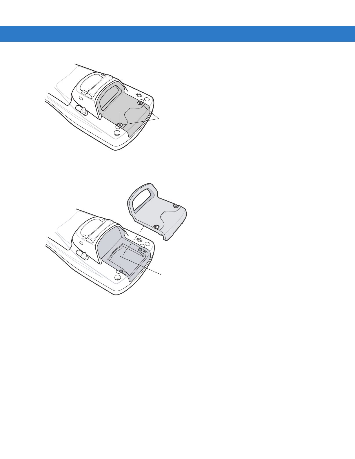
Battery Adapter Clip
Battery Door Switch
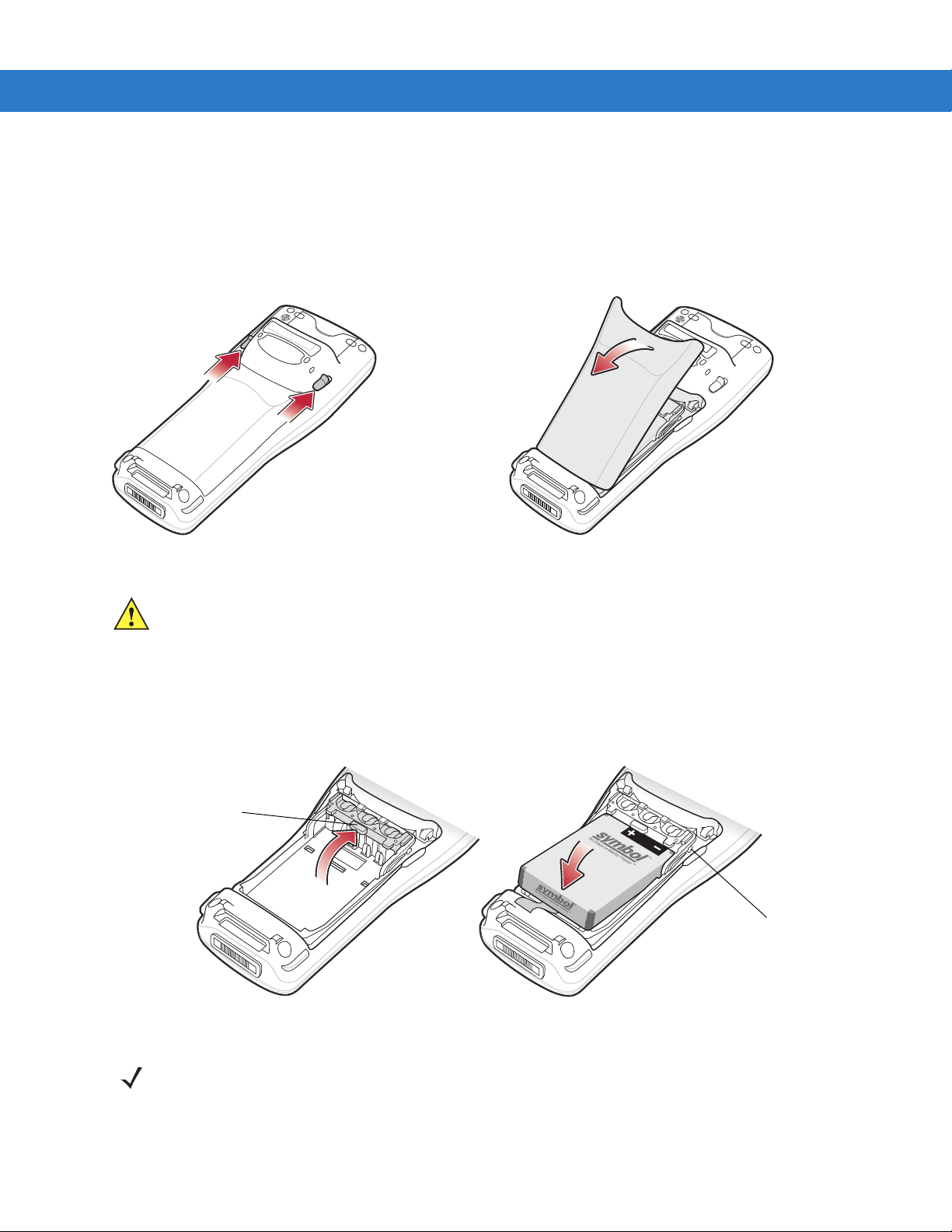
Li-ion Battery Installation
To install the Li-ion batte ry:
1. Pull back the two battery door latches.
2. Lift the battery door.
Figure 1-2
3. With your index and middle fingers holding the sides of the battery adapter clip, push toward the top of the
Battery Door Removal
CAUTION Ensure the battery adapter clip is positioned correctly or damage to the battery adapter clip and
battery door may occur.
Avoid touching the contacts when positioning the battery adapter clip.
mobile computer until it is latched in the up position.
4. Insert the battery into the battery well top first.
Figure 1-3
5. Replace the battery door bottom first and press down until it snaps into place.
Li-ion Battery Insertion
NOTE The battery door switch detects if the battery door is installed properly. The mobile computer does not turn
on if the battery door is not in place.
Page 17
Getting Started 1 - 5
Battery Adapter Clip
Battery Door Switch
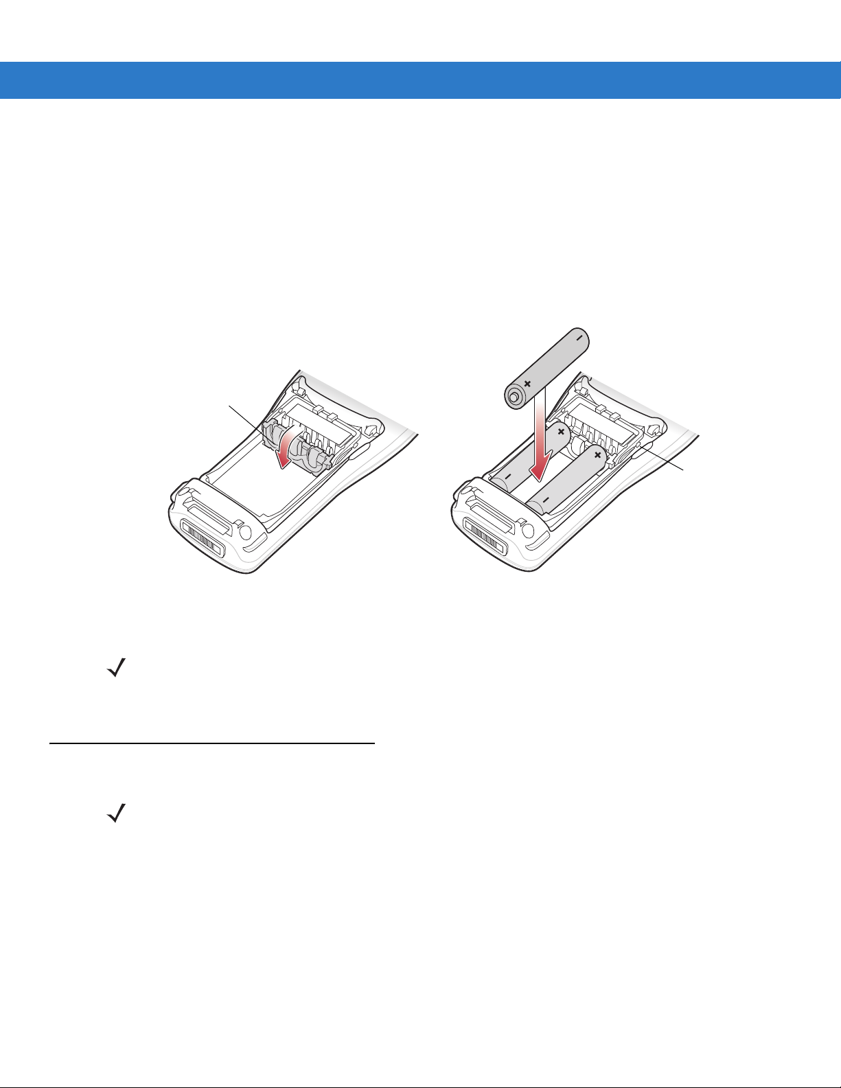
AAA Battery Installation
To install the AAA batteries:
1. Pull back the two battery door latches.
2. Lift the battery cover.
3. With your index and middle fingers holding the sides of the battery adapter clip, push towa rd the bottom of the
mobile computer until it is latched in the down position.
4. Insert the three AAA batteries into the battery well, noting the positions of the batteries.
Figure 1-4
5. Replace the battery door bottom first and press down until it snaps into place.
Battery Charging
Use the mobile computer’s cradles, charge cables, and spare battery chargers to charge the mobile computer’s
main Li-ion battery.
Before using the mobile computer for the first time, fully charge the main Li-ion battery. When the Li-ion battery is
fully charged the Charge LED remains lit. See Table 1-2 on page 1-6. Charge time for the Li-ion battery is usually
less than four hours. Charge the mobile computer using a cradle or charge cable, or remove and charge the main
Li-ion battery using a spare battery charger.
The mobile computer is equipped with a memory backup battery which automatically charges from the main
battery . Whe n the mobile comp uter is used for the first time , the backup battery requires approxima tely 20 hours to
fully charge. This is also true any time the backup battery is discharged which occurs when the main battery is
removed for several hours. The backup battery retains data in memory for at least 30 minutes after the mobile
AAA Battery Installation
NOTE The battery door switch detects if the battery door is installed properly. The mobile computer does not turn
on if the battery door is not in place.
NOTE Rechargeable AAA batteries cannot be recharged in the mobile computer. Refer to the rechargeable AAA
battery product information for charging instructions.
Page 18

1 - 6 MC1000 with Windows CE 4.2 User Guide
computer's main battery is removed. When the mobile computer reaches a very low battery state, the combination
of main battery and backup battery retains data in memor y for at least 72 hours.
NOTE Do not remove the main battery within the first 15 hours of use. If the main battery is removed before the
backup battery is fully charged, data may be lost.
Use the following accessories to charge the Li-ion battery:
•
Cradles:
• Single Slot Serial/USB cradle
• Four Slot USB cradle.
•
Cables (and a power supply):
• USB Client Charge cable
• RS232 Charge cable.
•
Spare Battery Charger:
• Single Slot Serial/USB cradle.
To charge the mobile computer Li-ion and backup batteries, use a cradle or a charge cable. The charge cable
requires a Symbol approved power supply.
•
Cradles
Insert the mobile computer into a cradle. See Chapter 3, Accessor ies for accessory setup. The mobile
computer starts to charge automatically. The Charge LED lights to indicate the charge status. See Table 1-2
for charging indications.
•
Cables
Connect a charge cable to the appropriate power source and connect the other end of the charge cable to
the mobile computer. See Chapter 3, Accessories for accessory setup. The mobile computer starts to charge
automatically. The Charge LED lights to indicate the charge status. See Table 1-2 for charging indications.
Table 1-2
Off Mobile computer is not placed correctly in the cradl e; charge cab le is no t connected
Slow Blinking Amber Mobile computer is charging.
Solid Amber Charging is complete.
Mobile Computer Charging LED Indicator
Status Indication
correctly; charger is not powered.
Note: When the Li-ion battery is initially inserted in the mobile c omputer, the Charge
LED flashes once if the battery power is low or the battery is not fully inserted.
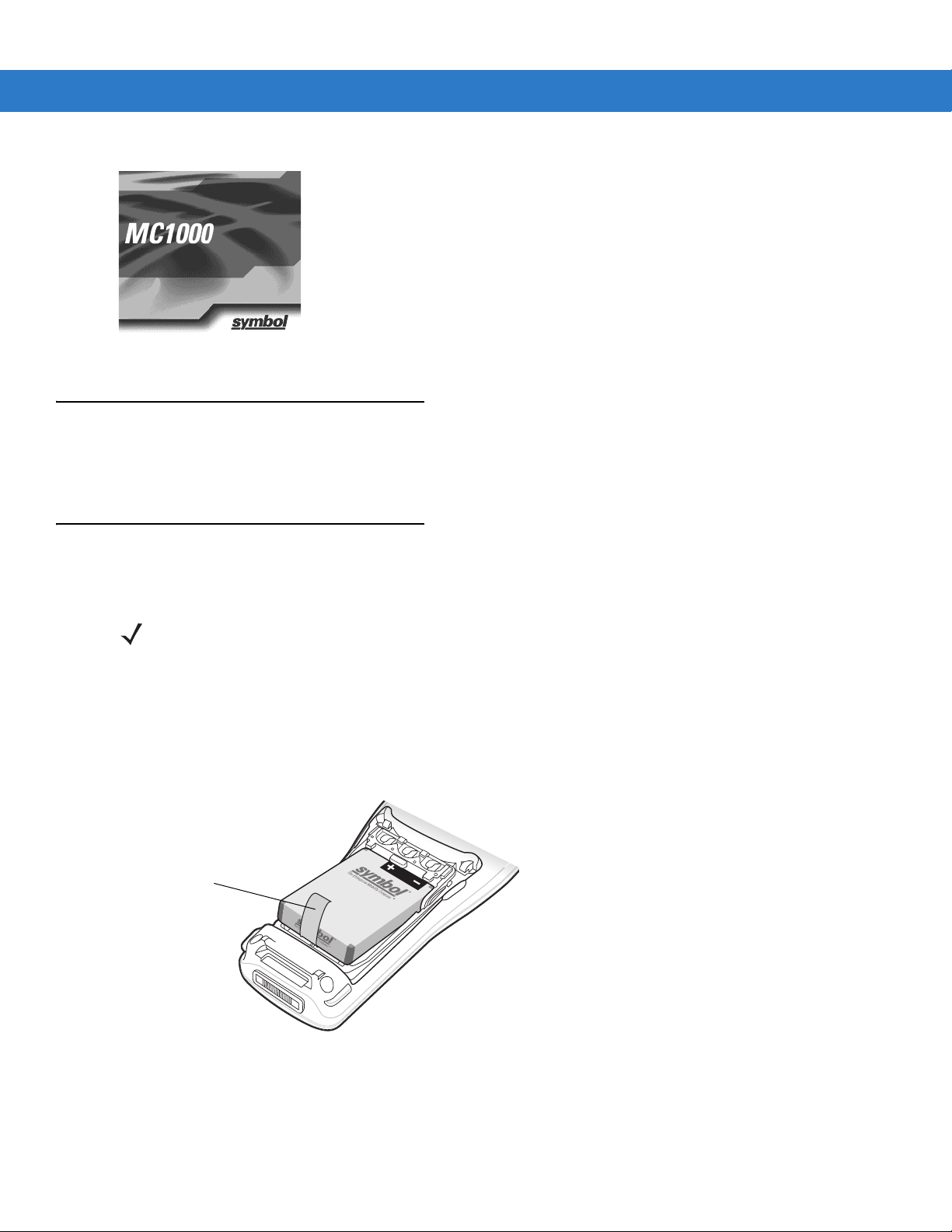
Starting the Mobile Computer
When the mobile computer is powered on for the first time, it initializes. The splash screen appears for a short
period of time. If the mobile computer does not power on, see Resetting the Mobile Computer on page 2-12.
Page 19
Getting Started 1 - 7
Battery Tab
Figure 1-5
Splash Screen
Waking the Mobile Computer
Use the wakeup condition settings to define what actions wa ke up the mobile computer. The settings are subject to
change/update. See Waking the Mobile Computer on page 2-13.
Li-ion Battery Removal
To remove the Li-ion battery:
NOTE Pulling back the left battery door latch places the mobile computer in suspend mode.
1. Press the red Power button to turn off the screen and place the mobile computer in suspend mode.
2. Pull back the two battery door latches.
3. Lift the battery door.
4. Pull the battery tab up to remove the battery.
Figure 1-6
Li-ion Battery Removal
Page 20
1 - 8 MC1000 with Windows CE 4.2 User Guide
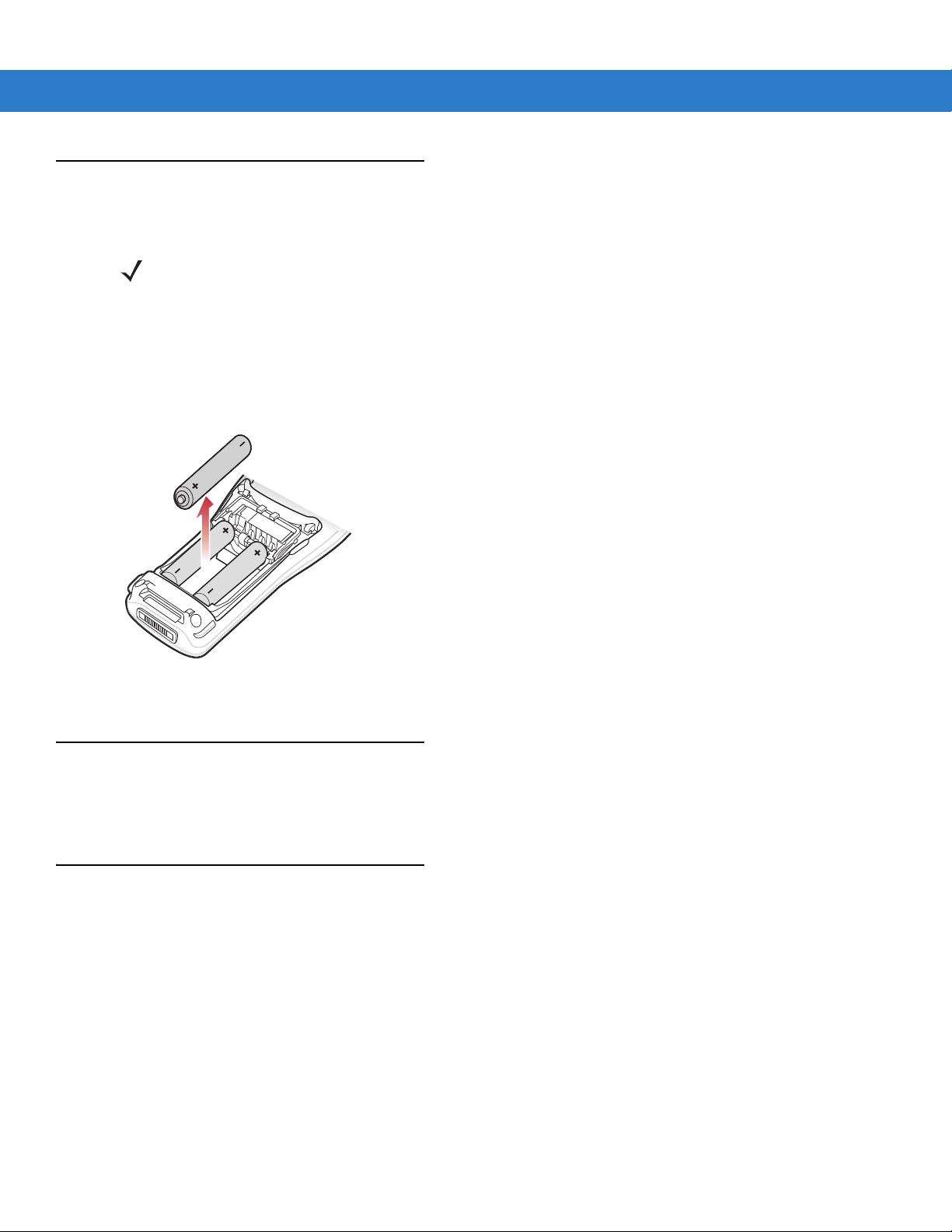
AAA Batteries Removal
To remove the AAA batteries:
NOTE Pulling back the left battery door latch places the mobile computer in suspend mode.
1. Press the red Power button to turn off the screen and place the mobile computer in suspend mode.
2. Pull back the two battery door latches.
3. Lift the battery door.
4. Remove the three AAA batteries from the mobile computer.
Figure 1-7
AAA Battery Removal
Spare Battery Charging
Use one of two accessories to charge spare Li-ion batteries. See to Chapter 3, Accessories for more information
on spare battery charging.
SD Memory Card
Use a Secure Digital (SD) memory card to store application data. To install an SD memory card:
1. Press the red Power button to turn off the screen and place the mobile computer in suspend mode.
2. Loosen the two captive screws securing the SD card cover.
Page 21
Getting Started 1 - 9
Captive Screws
SD Card Slot
Figure 1-8
3. Remove the SD card cover.
Figure 1-9
4. Insert the SD memory card into the SD card slot. Note the position of the notch on SD card.
SD Card Cover Screw Removal
SD Card Cover Removal
Page 22

1 - 10 MC1000 with Windows CE 4.2 User Guide
Figure 1-10
5. Replace the SD card cover.
6. Secure the two captive screws.
Wrist Strap
The wrist strap can be installed on either the right or left tether point. To install the wrist strap:
1. Thread the wrist strap loop through the tether point.
Figure 1-11
SD Card Installation
Insert Loop into Tether Point
2. Slip the end of the wrist strap through the loop and pull taught.
Figure 1-12
Slip Wrist Strap Through Loop
Page 23

Handstrap
Handstrap Clip
Handstrap Loop
Install the optional handstrap on either the right or left tether point. To install the handstrap:
1. Insert the handstrap clip into the slot at the bottom of the mobile computer.
Getting Started 1 - 11
Figure 1-13
2. Press the mobile computer down to force the handstrap clip into place.
Figure 1-14
3. Thread the handstrap loop through the tether point.
Insert Handstrap Clip
Press Mobile Computer Down
Figure 1-15
4. Slip the Velcro en d of the handstrap through the loop and pull taught.
Insert Loop into Tether Point
Page 24

1 - 12 MC1000 with Windows CE 4.2 User Guide
Figure 1-16
5. Slide the Velcro end through the clip.
Figure 1-17
Slip End Through Loop
Slide Handstrap through Clip
Page 25

Chapter 2 Operating the MC1000
Introduction
This chapter provides basic instructions for using and navigating the mobile computer.
Power Button
Press the red Power button to toggle the mobile computer between suspend and resume states. The display is off
in suspend state and it is on in resume state.
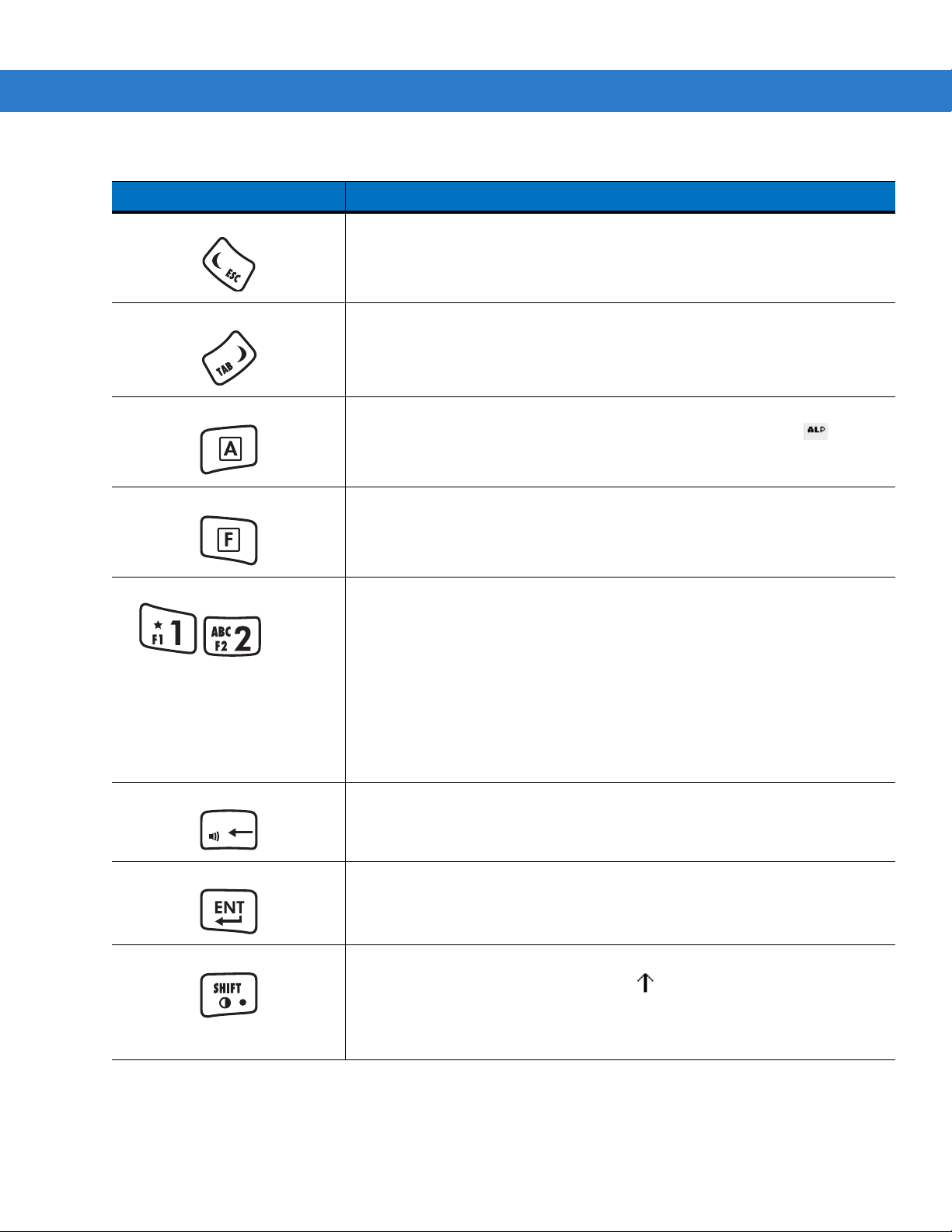
Keypad
The keypad contains a Power button, application keys, scroll keys, and function keys. The keypad is color-coded
to indicate the alternate function keys (blue and orange). Note that an a pplication can change the keypad fun ctions
so the mobile computer’s keypad may not function exactly as described. See Table 2-1 on page 2-2 for key and
button descriptions.
Page 26

2 - 2 MC1000 with Windows CE 4.2 User Guide
ALT
Figure 2-1
Table 2-1
Power Button (red) Toggles the mobile computer in and out of suspend mode. T oggles the screen on
Scan (yellow) Activates the laser scanner. Used in scanning applications.
CTRL
ALT
MC1000 Keypad
Keypad Descriptions
Key Description
and off.
Moves up from one item to another. Scrolls a window up.
CTRL
Functions as a
on the taskbar. See
Moves down from one item to another. Scrolls a window down.
Functions as an
on the taskbar. See
key when used with the blue F key. The icon appears
Table 2-3 on page 2-7
ALT
key when used with the blue F key. The icon appears
Table 2-3 on page 2-7
for more information.
for more information.
Page 27
Operating the MC1000 2 - 3
. . .
DEL
Table 2-1
Keypad Descriptions (Continued)
Key Description
ESC
Moves left from one item to another. Scrolls a window left.
Functions as an
TAB
Moves right from one item to another. Scrolls a window right.
Functions as a
A
(orange) Locks the keypad in the alpha mode. Press the orange A key to access the
ESC
key when used with the blue F key.
TAB
key when used with the blue F key.
alternate alphabetic characters (shown on the keys in orange). The icon
appears on the taskbar. See
and release the
F
(blue) Press and release the blue F key to activate the keypad alternate functions
A
key again to return to the numeric keypad functions.
Table 2-3 on page 2-7
for more information. Press
(shown on the key in blue).
Numeric/Alpha/Function Numeric mode by default, alpha when the orange
when the blue
F
key is selected.
A
key is selected, or a function
In alpha mode, produces the lower case alphabetic characters listed on the key.
Each key press produces the next alphabetic character in sequence. For
example, press the orange
letter ‘g’; quickly press the
Press the
SHIFT
key in alpha mode to produce the upper case alphabetic
characters on the key. For example, press the orange
key and then press the
and then quickly press the
A
key and then press the 4 key once to produce the
4
key three times to produce the letter ‘i’.
A
key, press the
4
key once to produce the letter ‘G’; press the
4
key three times to produce the letter ‘I’.
SHIFT
SHIFT
key
DEL
Backspace key by default and
Increases or decreases the speaker volume when used with the blue
Adjusting the Beeper Volume on page 2-5
ENT
SHIFT Press the orange
Executes a selected item or function.
A
key and then press and release the
the keypad alternate
Table 2-3 on page 2-7
Adjusts the screen contrast when used with the blue
Screen Contrast on page 2-5
DEL
key with the orange A key activated.
for more information.
SHIFT
key to activate
SHIFT
function. The icon appears on the taskbar. See
for more information.
F
key. See
Adjusting the
for more information.
F
key . See
Page 28

2 - 4 MC1000 with Windows CE 4.2 User Guide
Using the Keypad to Navigate Applications
The mobile computer screen is a non-touch screen and therefore navigation and control of an application is
performed using the keypad.
Key Combinations
The mobile computer uses special key combinations to easily navigate applications. Table 2-2 lists the key
combinations required to perform various application navigation and control.
Table 2-2
Key Combinations
Action Key Combination
Access the Start menu on the Task Bar Press F -
CTRL
Switch fields within an application Press F - TAB
Close windows or cancel operations Press F - ESC
F
-
ALT
Access the Task Manager Press
Minimize current window Press F Access a menu bar Press F Press a button in an application window. Press F Toggle IME mode on/off (Simplified Chinese only) Press F -
- F -
ALT
- F -
ALT
- F -
TAB
until the button is highlighted. Press A -
CTRL
Selecting Items
Use a combination of key sequences to select items in a folder or list.
To select continuous items in a folder or list:
1. Open the folder or list.
- F -
TAB
ESC
ALT
-
SP ACE
ESC
SP ACE
2. Use the scroll keys to move to the first item to select.
3. Press A to activate the alpha mode.
4. Press SHIFT - scroll key (either up or down) to select the next item.
5. Repeat the SHIFT - scroll key combination to select remaining items.
6. Perform the desired function.
To select multiple items in a folder or list:
1. Open the folder or list.
2. Press A to activate the alpha mode.
3. Use the scroll keys to move to the first item.
4. Press F- CTRL - scroll key to move within the list. The item name is outlined.
5. Repeat step 3 to move to the desired item.
6. Press SPACE to highlight the item.
Page 29

7. Repeat steps 3 through 5 until all items are selected.
8. Perform the desired function.
Adjusting the Beeper Volume
To adjust th e be ep e r volum e:
1. Press F - DEL. The volume control box appears.
Operating the MC1000 2 - 5
Figure 2-2
2. Use the scroll up or scroll down keys to adjust the volume.
3. After three seconds of inactivity , the settings are saved and the box disappears.
Volume Control Box
Adjusting the Screen Contrast
To adjust the screen contrast:
Page 30

2 - 6 MC1000 with Windows CE 4.2 User Guide
1. Press F - SHIFT. The contrast control box appears.
Figure 2-3
2. Use the scroll up or scroll down keys to adjust the contrast.
3. After three seconds of inactivity , the settings are saved and the box disappears.
Contrast Control Box
Screen
The mobile computer’s screen is a non-touch screen. All navigation of applications is performed using the keyp ad.
See Using the Keypad to Navigate Applications on page 2-4 for more information.
Taskbar
The taskbar (at the bottom of the screen) displays the Start button, active programs, and status icons. Table 2-3
describes the status icons.
•
Start button
Opens the Start menu for accessing the Control Panel and programs.
•
Active Programs
The active applications’ icons appear in the taskbar. If more than one program is active, use the Task
Manager to toggle between the active programs.
Page 31

Operating the MC1000 2 - 7
Start Button
Application and Status Icons
Active Programs
ALT
•
Status Icons
The keypad mode icons indicate the function key status. If the F, A, SHIFT, or CTRL functions are active the
appropriate icon appears in the taskbar. The power status icons indicate if the mobile computer is connected
to an AC power source, if it is charging, or the remaining power of the battery.
Figure 2-4
Table 2-3
Taskbar
Status Icons
Icon Description
Indicates that the mobile computer is charging.
Indicates the battery charge status in 10% increments from 10% to 100%.
Indicates that the battery is fully charged and the mobile computer is running on external AC power.
Indicates IP status. Only displays when the mobile computer is in emulation mode.
Indicates that the ActiveSync application is running.
Indicates that the
Indicates that the
Indicates that the
Indicates that the
SHIFT
F
CTRL
ALT
character function is selected.
key (function) is selected.
character function is selected.
character function is selected.
Indicates that the mobile computer is in alpha mode.
Use the scroll arrows to scroll left or right to reveal hidden program and status icons.
Page 32
2 - 8 MC1000 with Windows CE 4.2 User Guide
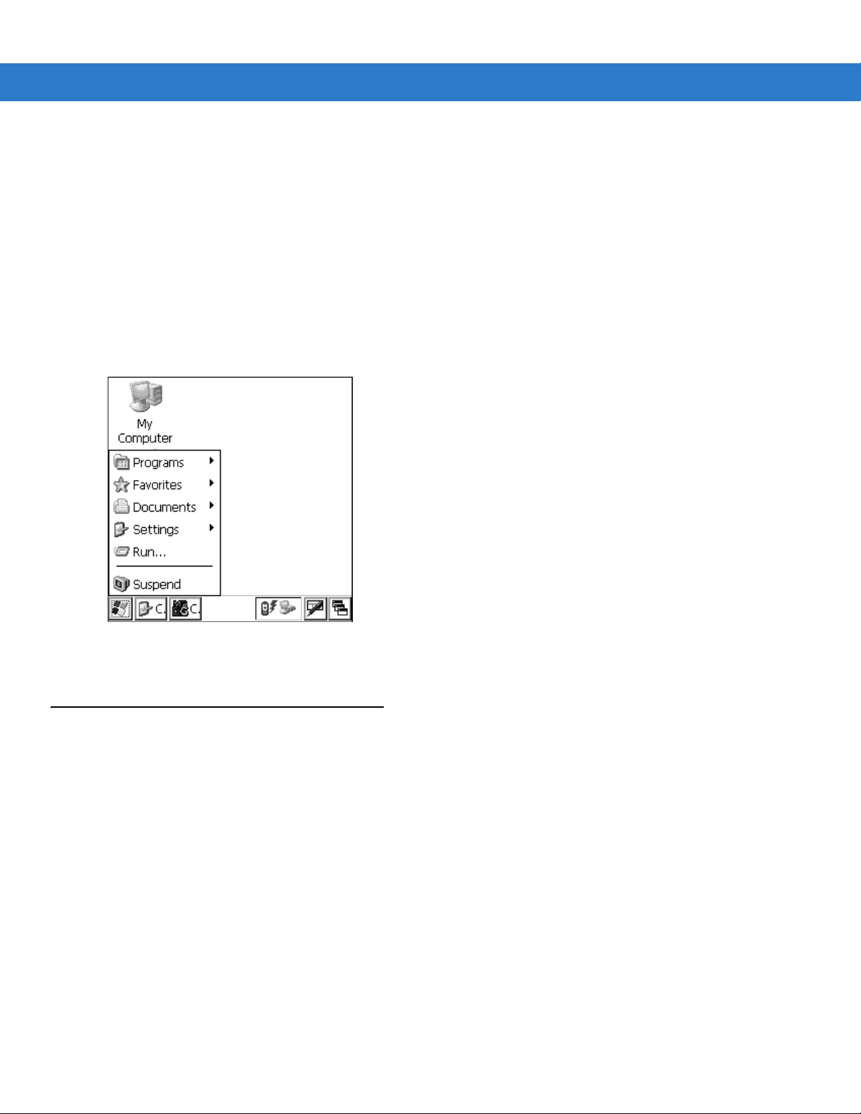
Start Button
Press F - CTRL - F - ESC to launch the Start menu.
•
Programs: Use to access available programs
•
Favorites: Displays files in the Favorites directory
•
Documents: Displays files in the Documents directory
•
Settings: Accesses the Control Panel, the Network and Dial-up Connections, and the Taskbar and Start
menu properties
•
Run . . . : Runs a program or application
•
Suspend: Suspends the mobile computer.
Figure 2-5
Use the scroll keys to navigate to a specific entry and then press the ENT key to select it.
Start Menu
Entering Information
To enter information:
•
Use the keypad.
•
Scan bar code data into data fields.
•
Use Microsoft® ActiveSync® to synchronize or copy information from the host computer to the mobile
computer. For more information on ActiveSync, refer to the MC1000 with Windows CE 4.2 Integrator Guide.
Entering Information Using the Keypad
The alphanumeric keypads produce the 26-character alphabet (A-Z), numbers (0-9), function keys, and assorted
characters. The keypads’ default characters/functions are printed white, the alpha character/functions are printed
orange, and the function character/functions are printed blue. See Keypad on page 2-1 for keypad configurations.
Page 33

Operating the MC1000 2 - 9
Entering Data via the Bar Code Scanner
The integrated laser bar code scanner use s the Scan W edge program to scan dat a into dat a fields in the sa me way
data is entered via the keypad.
To scan bar codes with the mobile computer:
1. Ensure that the mobile computer is loaded with a scanning application.
2. Aim the mobile computer at the bar code.
Figure 2-6
Figure 2-7
3. Press the scan button. Ensure the red scan beam covers the entire bar code. The Scan LED illuminates red to
Scanning
NOTE Do not cover the scan window with your finger.
Obstructing Scan Window
indicate that the laser is on. The Scan LED illuminates green and a beep sounds to indicate a successful
decode.
Page 34

2 - 10 MC1000 with Windows CE 4.2 User Guide
Wrong
Right
Figure 2-8
Optimal scanning distance varies with bar code density and scanner optics.
Laser Aiming
• Hold the scanner farther away for larger symbols.
• Move the scanner closer for symbols with bars that are close together.
NOTE Scanning procedures depend on the application and mobile computer configuration. An application may
use different scanning procedures from the one above.
Scan Indicator LED
Table 2-4 lists the Scan LED indicator status.
Table 2-4
Off Not scanning.
Solid Red Laser enabled, scanning in process.
Solid Green Successful decode.
Scan LED Indicator
LED Status Indication
Scanning Considerations
Scanning is a simple matter of aim, scan and decode. However, to optimize scanning performance consider the
range and the scanning angle:
•
Range
Any scanning device decodes well over a particular wo rking range — minimum and maximum distances from
the bar code. This range varies according to bar code density and scanning device optics.
Scanning within range brings quick and constant decodes; scanning too close or too far away prevents
decodes. Move the scanner closer and further away to find the right working range for the bar codes being
scanned. However, the situation is complicated by the availability of various integrated scanning modules.
The best way to specify the appropriate working range per bar code density is through a chart called a
decode zone for each scan module. A decode zone simply plots working range as a function of minimum
element widths of bar code symbols.
•
Angle
Scanning angle is important for promoting quick de codes. When laser beams reflect directly back into the
scanner from the bar code, this specular reflection can “blind” the scanner.
To avoid this, scan the bar code so that the beam does not bounce directly back. But don’t scan at too sharp
an angle; the scanner needs to collect scattered reflections from the scan to make a successful decode.
Practice quickly shows what tolerances to work within.
NOTE Contact the Motorola Enterprise Mobility support if persistent scanning difficulties develop. Decoding
properly printed bar codes should be quick and effortless.
Page 35

Operating the MC1000 2 - 11
in.
cm
5 mil
4.9
7.5 mil
7.9
100% UPC
12.7
17.9
24.1
20 mil
40 mil
30.6
55 mil
*Minimum distance determined by symbol length and scan angle
0
6
12
0
15.3
30.5
45.7
15.3
30.5
45.7
6
12
in. cm
W
i
d
t
h
o
f
F
i
e
l
d
Depth of Field
0
0
10
25.4
20
50.8
30
76.2
18
2.1
2.2
2.6
40
101.6
18
*
Note: Typical performance at 73° F (23° C)
on high quality symbols.
Laser Decode Ranges
Figure 2-9 shows the laser decode ranges a nd Table 2-5 on page 2-11 lists the decode ranges for the selected bar
code densities. The minimum element width (or “symbol density”) is the width in mils of the narrowest element (bar
or space) in the symbol. The maximum usable length of a symbol at any given range is shown below.
Figure 2-9
Table 2-5
MC1000 Laser Decode Ranges
MC1000 Laser Decode Ranges
Bar Code Density
5.0 mil
7.5 mil
10 mil
Note: Minimum distance determined by symbol length and scan angle.
2.6 in
6.60 cm
2.2 in
5.59 cm
1.9 in
4.83 cm
Ranges
Near Far
4.9 in
12.45 cm
7.9 in
20.07 cm
10.8 in
67.95cm
Page 36

2 - 12 MC1000 with Windows CE 4.2 User Guide
Table 2-5
100% UPC
20 mil (See Note)
40 mil (See Note)
55 mil (See Note)
Note: Minimum distance determined by symbol length and scan angle.
MC1000 Laser Decode Ranges (Continued)
Bar Code Density
Resetting the Mobile Computer
If the mobile computer stops responding to input, reset it. There are two types of resets, warm boot and cold boot.
A warm boot restarts the mobile computer by closing all running programs. All data that is not saved is lost.
2.1 in
5.33 cm
Ranges
Near Far
12.7 in
32.26 cm
17.9 in
45.47 cm
24.1 in
67.06 cm
30.6 in
77.72 cm
A cold boot also restarts the mobile computer, but erases all stored records and entries from RAM. In addition it
returns formats, preferences, and other settings to the factory default settings.
Perform a warm boot first. This restarts the mobile computer and saves all stored records and entries. If the mobile
computer still does not respond, perform a cold boot.
Performing a Warm Boot
To perform a warm boot, press and hold the Power button until a message appears to warm boot the mobile
computer. As the mobile computer initializes MC1000 desktop appears.
CAUTION Files that remain open during a warm boot may not be retained.
Performing a Cold Boot
A cold boot restarts the mobile computer and e rases all u ser sto red re co rd s and en tr ies fr om RAM. Ne ve r pe rfor m
a cold boot unless a warm boot does not solve the problem.
CAUTION A cold boot resets the mobile computer to the default settings and removes all added applications and all stored
data. Do not cold boot without support desk approval.
To perform a cold boot press and hold the Power for at least 15 seconds. As the mobile computer initializes its
Flash File system, the splash window appears for about 15 seconds.
Page 37

Waking the Mobile Computer
The wakeup conditions define what actions wake up the mobile computer. These settings are configurable and the
factory default settings shown in Table 2-6 are subject to change/update.
Operating the MC1000 2 - 13
Table 2-6
Status Description Conditions for Wakeup
Power
Off
Auto Off When the automatic power-off function places the
Wakeup Conditions (Default Settings)
When the mobile computer is set to the suspend mode
by pressing the
mobile computer.
mobile computer in suspend mode these actions wake
the mobile computer.
Power
button, these actions wake the
File System Directory Structure
The mobile computer directory structure displays all of the file folders, see Figure 2-10. The pre-installed folders
are in flash file system memory and optional removable storage devices (SD cards).
•
Power button is pressed.
•
AC power is added or removed.
•
Cradle/cable connect or disconnect.
Key or scan button is pressed.
Real Time Clock set to wake up.
•
Power button is pressed.
•
AC power added or removed.
•
Cradle/cable connect or disconnect.
Key or scan button is pressed.
Real Time Clock set to wake up.
Figure 2-10
•
•
Mobile Computer Directory Structure
Application and Platform folders are located in flash file system memory.
The Windows, Program Files, profiles, and My Documents folders are composite, RAM-based folders
generated from ROM (many of these files are marked read only).
Page 38

2 - 14 MC1000 with Windows CE 4.2 User Guide
•
The Network folder is a link to file systems mapped using the network redirector. The files do not physically
reside on the mobile computer.
•
The Temp and Recycled folders typically contain RAM based files.
NOTE All files copied to the RAM-based folders are lost after a cold boot.
Page 39

Chapter 3 Accessories
Introduction
The MC1000 accessories provide a variety of product support capabilities. Accessories include cradles and cables.
Cradles
•
Single Slot Serial/USB cradle charges the mobile computer main battery and/or a sp are Li-ion battery. It also
synchronizes the mobile computer with a host computer through either a serial or USB co nnection.
•
Four Slot USB cradle charges up to four mobile computers. It also synchronizes up to fou r mobile compu ters
with a host computer through a USB connection.
Cables
The cables snap on to the mobile computer and are used to connect external devices to the mobile computer.
•
USB Client Charge Cable
•
RS232 Charge Cable.
Page 40

3 - 2 MC1000 with Windows CE 4.2 User Guide
Charge LED
Mobile
Computer Slot
Spare
Battery
Spare
Battery
Charging
LED
Power Port
Serial Port
USB Port
Scan LED
Single Slot Serial/USB Cradle
This section describes how use the Single Slot Serial/USB Cradle with the mobile computer.
Figure 3-1
Single Slot USB Cradle
NOTE Use only a Symbol-approved power supply output rated 5.4 VDC and minimum 3 A. The power supply is
certified to EN60950 with SELV outputs. Use of alternative power supply will invalidate any approval given
to this device and may be dangerous.
HINWEIS Benutzen Sie nur eine Symbol T echnologies genehmigt in den Ausgabe: 5.4 VDC und minimum 3A. Die
Stromversorgung ist bescheinigt nach EN60950 mit SELV Ausgaben. Bei Verwendung eines anderen
Netzteils werden alle für das Gerät gewährten Genehmigungen außer Kraft gesetzt, und der Betrieb
kann gefährlich sein.
The Single Slot Serial/USB cradle:
•
Provides 5.4 VDC power for operating the mobile computer.
•
Provides a serial port and USB port (mini B receptacle) for data commu nication between the mobile
computer and a host computer.
•
Synchronizes information between the mobile computer and a host computer (with customized or third p arty
software, it can also synchronize the mobile computer with corporat e da tabase s).
•
Provides serial connection through the serial pass-through port for communication with a serial device, such
as a host computer (cradle serial communication cable is available). For communication setup procedures,
refer to the MC1000 with Windows CE 4.2 Integrator Guide.
Page 41

Accessories 3 - 3
•
Provides USB connection through the USB pass-through port for communication with a USB device, such as
a host computer (cradle USB communication cable is available). For communication setup procedures, refer
to the MC1000 with Windows CE 4.2 Integrator Guide.
•
Charges the mobile computer’s Li-ion battery.
•
Charges a spare Li-ion battery.
Battery Charging
The Single Slot Serial/USB cradle can charge the mobile computer’s main Li-ion battery and a spare Li-ion battery
simultaneously.
NOTE Re-chargeable AAA batteries do not charge in the mobile computer when the mobile computer is placed
in the Single Slot Serial/USB cradle.
To charge the battery for your mobile device, battery and charger temperatures must be between +32° F
and +104° F (0° C to +40° C).
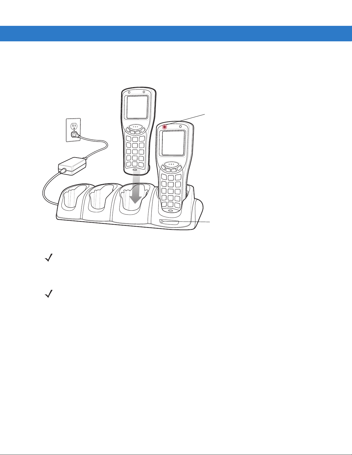
To charge the mobile computer:
1. Connect the Single Sot Serial/USB cradle to a power source.
2. Firmly press the mobile computer into the mobile computer slot. The mobile co mputer’s Charge LED indicates
the mobile computer battery charging status.
3. When charging is completed, hold the cradle with one hand and lift the mobile computer out of the cradle with
the other hand.
To charge the spare Li-ion battery:
1. Connect the Single Sot Serial/USB cradle to a power source.
2. Align the battery contacts as shown on the cradle. Note the polarity icon on the batte ry.
3. Insert the battery into the battery slot noting the battery polarity.
4. Gently press down on the battery to ensure proper contact.
The cradle spare battery charging LED (see Figure 3-1 on page 3-2) indicates the spare battery charging status.
See Table 3-1 for charging status indications.
To remove the spare battery, pull the battery away from the mobile computer slot and lift the battery out of the slot.
The Li-ion battery charges in less than four hours.
Table 3-1
LED Charging Status Indicators
LED Indication
Mobile Computer Charging (LED on mobile computer)
Off Mobile computer not in cradle; mobile computer not placed correctly; cradle is not
powered, or environment is outside the battery charging temperature range.
Slow Blinking Amber Mobile computer is charging.
Solid Amber Charging complete.
Spare Battery Charging (LED on cradle)
Page 42

3 - 4 MC1000 with Windows CE 4.2 User Guide
Table 3-1
Off No spare battery in slot; spare battery not placed correctly; cradle is not powered,
Slow Blinking Amber Spare battery is charging.
Solid Amber Charging complete.
LED Charging Status Indicators
LED Indication
or environment is outside the battery charging temperature range.
Page 43
Four Slot USB Cradle
Power LED
Charge LED
This section describes how to use the Four Slot USB cradle with the mobile computer.
Accessories 3 - 5
Figure 3-2
The Four Slot USB cradle:
•
•
•
Four Slot USB Cradle
NOTE Use only a Symbol-approved power supply output rated 12.0 VDC and minimum 3.3 A. The power supply
is certified to EN60950 with SELV outputs. Use of alternative power supply will invalidate any approval
given to this device and may be dangerous.
HINWEIS Benutzen Sie nur eine Symbol Technologies genehmigt in den Ausgabe: 12 VDC und minimum 3A. Die
Stromversorgung ist bescheinigt nach EN60950 mit SELV Ausgaben. Bei Verwendung eines anderen
Netzteils werden alle für das Gerät gewährten Genehmigungen außer Kraft gesetzt, und der Betrieb
kann gefährlich sein.
Provides 5.4 VDC power for operating the mobile computer.
Provides communication with a host computer via an internal USB hub.
Simultaneously charges up to four mobile computers.
Page 44

3 - 6 MC1000 with Windows CE 4.2 User Guide
Battery Charging
NOTE Re-chargeable AAA batteries do not charge in the mobile computer when the mobile computer is placed
in the Four Slot USB cradle.
To charge the battery for your mobile device, battery and charger temperatures must be between +32° F
and +104° F (0° C to +40° C).
UConnect software must be loaded onto the mobile computer for proper ActiveSync operation. Refer to
the MC1000 with Windows CE 4.2 Integrator Guide for installing UConnect onto the mobile computer.
The Four Slot USB cradle can charge up to four mobile computers simultaneously. The Li-ion battery charges in
approximately four hours. To charge the mobile computer:
1. Connect the Four Slot USB cradle to a power source.
2. Firmly press the mobile computer into the mobile computer slot.
3. The mobile computer’s Charge LED indicates the mobile computer battery charging status.
4. When charging is completed, hold the cradle with one hand and lift the mobile computer out of the cradle with
the other hand.
Cables
This section describes how to set up and use the cables. The cables:
•
provide the mobile computer’s operating power and battery charging power when used with the Symbol
approved power supply.
•
provide serial connection through th e ser ia l pass-thro u gh port for communication with a serial device, such
as a host computer. For communication setup procedures, refer to the MC1000 Integrator Guide.
•
provide USB connection through the USB pass-through port for communication with a USB device, such as a
host computer . For communication setup procedures, refer to the MC1000 Integrator Guide.
•
provide printing capabilities to an approved printer.
NOTE Use only a Symbol-approved power supply output rated 5.4 VDC and minimum 3 A. The power supply is
certified to EN60950 with SELV outputs. Use of alternative power supply will invalidate any approval given
to this device and may be dangerous.
HINWEIS Benutzen Sie nur eine Symbol T echnologies genehmigt in den Ausgabe: 5.4 VDC und minimum 3A. Die
Stromversorgung ist bescheinigt nach EN60950 mit SELV Ausgaben. Bei Verwendung eines anderen
Netzteils werden alle für das Gerät gewährten Genehmigungen außer Kraft gesetzt, und der Betrieb
kann gefährlich sein.
Cable Connection
1. Slide the bottom of the mobile computer into the cable cup and gently press it down until it is firmly seated in
the cable cup.
Page 45

Accessories 3 - 7
Figure 3-3
2. Connect the other end of the cable to the appropriate host device.
3. For the RS-232 Serial Charge cable, connect the power supply.
Cable Connection
Battery Charging
NOTE To charge the battery for your mobile device, battery and charger temperatures must be between +32° F
and +104° F (0° C to +40° C).
The Serial Charge cable and the USB Charge cable can charge the mobile computer’s Li-ion battery. Connect the
cables as described above. The mobile computer’s Charge LED blinks amber to indicate that the battery is
charging and turns solid amber when the battery is completely charged. The Li-ion battery usually charges in less
than four hours. See Table 3-1 on page 3-3 for charging indication information.
Page 46

3 - 8 MC1000 with Windows CE 4.2 User Guide
Page 47

Chapter 4 Maintenance & Troubleshooting
Introduction
This chapter includes instructions on cleaning and storing the mobile computer, and provides troubleshooti ng
solutions for potential problems during mobile computer operation.
Maintaining the Mobile Computer
For trouble-free service, observe the following tips when using the mobile computer:
•
Do not scratch the screen of the mobile computer.
•
Although the mobile computer is water and dust resista nt, do not expose it to rain or moisture for an extend ed
period of time. In general, treat the mobile computer as a pocket calculator or other small electronic
instrument.
•
The screen of the mobile computer is glass. Do not to drop the mobile computer or subject it to stro ng impact.
•
Protect the mobile computer from temperature extremes. Do not leave it on the dashboard of a car on a hot
day, and keep it away from heat sources.
•
Do not store or use the mobile computer in any location that is extremely dusty, damp, or wet.
•
Use a soft lens cloth to clean the mobile computer. If the surface of the mobile computer screen becomes
soiled, clean it with a soft cloth moistened with a diluted window-cleaning solution.
•
Periodically replace the rechargeable Li-ion battery to ensure maximum battery life and product performance.
Battery life depends on individual usage patterns.
Page 48
4 - 2 MC1000 with Windows CE 4.2 User Guide
Troubleshooting
Mobile Computer
Table 4-1
Mobile computer does
not turn on.
Rechargeable Li-ion
battery did not charge.
Cannot see characters
on screen.
Troubleshooting the Mobile Computer
Problem Cause Solution
Main battery not
charged.
Main battery not
installed properly.
System crash. Perform a warm boot. If the mobile computer still does not turn
Li-ion battery failed. Replace the Li-ion battery. If the mobile computer still does not
Mobile computer
removed from cradle
while battery was
charging.
Extreme battery
temperature.
Mobile computer not
powered on.
Charge the Li-ion battery.
Replace the Li-ion battery or three AAA batteries.
Ensure battery is installed properly. See
Installation on page 1-3
on, perform a cold boot. See
on page 2-12
operate, try a warm boot, then a cold boot. See
Mobile Computer on page 2-12
Insert mobile computer in cradle and begin charging. The main
battery requires up to four hours to recharge fully.
Li-ion battery does not charge if battery temperature is below
32°F (0°C) or above 104°F (40°C).
Press the
.
Power
button.
.
Resetting the Mobile Computer
.
Main Battery
Resetting the
During data
communication, no data
was transmitted, or
transmitted data was
incomplete.
Mobile computer does
not emit sound.
Mobile computer
removed from cradle
or unplugged from
host computer during
communication.
Incorrect cable
configuration.
Communication
software was
incorrectly installed or
configured.
Volume setting is low
or turned off.
Replace the mobile computer in the cradle, or reattach the
cable and re-transmit.
See the system administrator.
Perform setup as described in the Integrator Guide.
Adjust volume setting.
Page 49

Maintenance & Troubleshooting 4 - 3
Table 4-1
Mobile computer turns
itself off.
A message appears
stating that the mobile
computer memory is full.
The mobile computer
does not accept scan
input.
Troubleshooting the Mobile Computer (Continued)
Problem Cause Solution
Mobile computer is
inactive.
Battery is depleted. Replace the battery.
Battery is not inserted
properly.
Too many files stored
on the mobile
computer.
Too many applications
installed on the mobile
computer.
Scanning application
is not loaded.
Unreadable bar code. Ensure the symbol is not defaced.
Distance between exit
window and bar code
is incorrect.
The mobile computer turns off after a period of inactivity. This
period can be set from one to five minutes, in one-minute
intervals.
Insert the battery properly. See
page 1-3
Delete unused memos and records. If necessary, save these
records on the host computer.
Remove unused installed applications from the mobile
computer to recover memory.
Verify that the mobile computer is loaded with a scanning
application. See the system administrator.
Ensure mobile computer is within proper scanning range.
.
Main Battery Installation on
Mobile computer is not
programmed for the
bar code type.
Mobile computer is not
programmed to
generate a beep.
Battery is low. Check the battery level. When the battery is low, the mobile
Ensure the mobile computer is programmed to accept the type
of bar code scanned.
Check that the application is set to generate a beep on good
decode.
computer automatically goes into suspend mode.
Page 50

4 - 4 MC1000 with Windows CE 4.2 User Guide
Single Slot Serial/USB Cradle
Table 4-2
Charge LEDs do not
light when mobile
computer or spare Li-ion
battery is inserted. See
Figure 3-1 on page 3-2
Mobile computer battery
is not charging.
Troubleshooting the Single Slot Serial/USB Cradle
Symptom Possible Cause Action
Cradle is not receiving power. Ensure the power cable is connected securely to both
the cradle and to AC power.
Mobile computer is not seated
correctly in the cradle.
.
Spare Li-ion battery is not
seated correctly in the cradle.
Extreme battery temperature. Li-ion battery does not charge if battery temperature is
Mobile computer was removed
from cradle or cradle was
unplugged from AC power too
soon.
Battery is faulty. Verify that other batteries charge properly. If so,
Mobile computer is not fully
seated in the cradle.
Remove and re-insert the mobile computer into the
cradle, ensuring it is firmly seated.
Remove and re-insert the spare Li-ion ba ttery into the
charging slot, ensuring it is correctly seated. Note the
polarity icon on the battery.
below 32°F (0°C) or above 104°F (40°C).
Ensure cradle is receiving power. Ensure mobile
computer is seated correctly. If a mobile computer
battery is fully depleted, it can take up to four hours to
fully recharge the battery.
replace the faulty battery.
Remove and re-insert the mobile computer into the
cradle, ensuring it is firmly seated.
Spare Li-ion battery is
not charging.
During data
communications, no
data was transmitted, or
transmitted data was
incomplete.
Extreme battery temperature. Li-ion battery does not charge if battery temperature is
below 32°F (0°C) or above 104°F (40°C).
Li-ion battery not fully seated in
charging slot.
Battery inserted incorrectly. Ensure the contacts are facing down and toward the
Battery is faulty. Verify that other batteries charge properly. If so,
Extreme battery temperature. Li-ion battery does not charge if battery temperature is
Mobile computer removed from
cradle during communications.
Incorrect cable configuration. See the system administrator.
Communications software is not
installed or configured properly.
Remove and re-insert the spare Li-ion ba ttery into the
cradle, ensuring it is correctly seated. Note the
polarity icon on the battery.
back of the cradle. Note the polarity icon on the
battery. Note the polarity icon on the battery.
replace the faulty battery.
below 32°F (0°C) or above 104°F (40°C).
Replace mobile computer in cradle and retransmit.
Perform setup as described in the MC1000 with
Windows CE 4.2 Integrator Guide.
Page 51

Four Slot USB Cradle
Maintenance & Troubleshooting 4 - 5
Table 4-3
Charge LEDs do not
light when mobile
computer is inserted.
Mobile computer
battery is not charging.
During data
communications, no
data was transmitted,
or transmitted data was
incomplete.
Troubleshooting the Four Slot USB Cradle
Symptom Possible Cause Action
Cradle is not receiving power. Ensure the power cable is connected securely to
both the cradle and to AC power.
Mobile computer is not seated
correctly in the cradle.
Extreme battery temperature. Li-ion battery does not charge if battery temperature
Mobile computer was removed
from cradle or cradle was
unplugged from AC power too
soon.
Li-ion battery is faulty. Verify that other batteries charge properly. If so,
Mobile computer is not fully
seated in the cradle.
Extreme battery temperature. Li-ion battery does not charge if battery temperature
Mobile computer removed from
cradle during communications.
Incorrect cable configuration. See the system administrator.
Communications software is not
installed or configured properly.
Remove and re-insert the mobile computer into the
cradle, ensuring it is firmly seated.
is below 32°F (0°C) or above 104°F (40°C).
Ensure cradle is receiving power. Ensure mobile
computer is seated correctly. If a mobile computer
battery is fully depleted, it can take up to four hours to
fully recharge the Li-ion battery.
replace the faulty battery.
Remove and re-insert the mobile computer into the
cradle, ensuring it is firmly seated.
is below 32°F (0°C) or above 104°F (40°C).
Replace mobile computer in cradle and retransmit.
Perform setup as described in the MC1000 with
Windows CE 4.2 Integrator Guide.
Page 52

4 - 6 MC1000 with Windows CE 4.2 User Guide
Cables
Table 4-4
Mobile computer
Charge LED does not
light when mobile
computer inserted.
Mobile computer
battery is not charging.
During data
communication, no
data was transmitted,
or transmitted data
was incomplete.
Troubleshooting the Cables
Symptom Possible Cause Action
Cable is not receiving
power.
Mobile computer is not
seated correctly in the
cable.
Extreme battery
temperature.
Mobile computer was
removed from cable or
cable was unplugged from
AC power too soon.
Li-ion battery is faulty. Verify that other batteries charge properly. If so, replace the
Mobile computer is not
fully seated in the cable.
Cable removed from
mobile computer during
communication.
Incorrect cable
configuration.
Ensure the power cable is connected securely to both the
cable and to AC power.
Remove and re-insert the mobile computer into the cable,
ensuring it is correctly seated.
Li-ion battery does not charge if battery temperature is below
32°F (0°C) or above 104°F (40°C).
Ensure cable is receiving power. Ensure mobile computer is
seated correctly. If a mobile computer battery is fully
depleted, it can take up to four hours to fully recharge a
battery.
faulty battery.
Remove and re-insert the mobile computer into the cable,
ensuring it is correctly seated.
Reattach cable to mobile computer and retransmit.
See the system administrator.
Communication software
is not installed or
configured properly.
Perform setup as described in the MC1000 with Windows CE
4.2 Integrator Guide.
Page 53

Appendix A Technical Specifications
Mobile Computer Technical Specifications
The following table summarizes the mobile computer’s intended operating environment.
Table A-1
Operating Temperature 14° to 122°F (-10° to +50°C)
Storage Temperature -40° to 158°F (-40° to 70°C)
Battery Charging Temperature -32° to 104°F (0° to 40°C)
Humidity 0% to 85% non-condensing at 122° F (50°C)
Electrostatic Discharge (ESD) +/-15 kV (air) (RH 50%); +/- 8 kV (contact)
Sealing IP54 category 2
Shock and Vibration Drop/Shock:
Mobile Computer Technical Specifications
2 times per side (12 drops total of the same unit) from a height of 4 feet
to concrete at -10°C, 23°C and 50°C
Tumble:
500, ½ meter tumbles (1 tumble = 2 drops)
Vibration:
4G's, random, 5 Hz to 2,000 Hz vibration
Cargo/Packaged:
Six (6) foot drop at 23°C, 5 Hz, Vibration < 20 lbs
Vehicle stacking 96", 23°C, and 85% relative humidity
Dimensions 6.42 in L x 2.54 in W x 1.50 in H
(163 mm L x 64.5 mm W x 38 mm H)
Weight (with Li-ion Battery) 7.23 oz (205 g)
Page 54

A - 2 MC1000 with Windows CE 4.2 User Guide
Table A-1
Mobile Computer Technical Specifications (Continued)
Display Non-touch monochrome
Main Battery Rechargeable Lithium-ion 1800 mAh minimum (3.7 VDC), or three AAA
Alkaline batteries
Backup Battery Ni-MH battery (rechargeable), 20 mAh (3.6 VDC) 3 cells
Operating Platform
Processor/Memory
Microsoft
Intel
®
Embedded Windows® CE 4.2 Core
®
XScale™ PXA 312MHz with 32MB RAM/32MB Flash
Interface RS-232, 115.2 kbps max
USB Client
Data Capture Code 39, Code 128, Code 93, Codabar, EAN-8, EAN-13, Interleaved 2
of 5, UPCA, UPCE and UPC/EAN Supplements,
RSS-14/Limited/Expanded, MSI Plessey, IATA 2 of 5, Coupon Code.
Secure Digital (SD) Cards The following Sandisk SD cards have been tested and qualified*:
SDSDB-64-201-80 (64 MB)
SDSDB-128-201-80 (128 MB)
SDSDB-512-201-80 (512 MB)
*Symbol disclaims all liability of any kind whatsoever, including without
limitations, liability under tort, contract, intellectual property rights or any
other legal theory, for the performance of the above Sandisk SD cards
and/or their interoperability (or the lack thereof) with any Symbol product,
and does not warrant or in any way guarantee that such Sandisk SD
cards will operate in conjunction, in combin ation or in integr ation with th e
MC1000 or any other Symbol product. The above information is offered
on an “as is” basis, and does not constitute business, le gal, professional,
technical or any other advice.
Page 55

Glossary
A
API. An interface by means of which one software component comm unicates with or controls another. Usually used to refer
to services provided by one software component to another, usually via software interrupts or function calls
Aperture. The opening in an optical system defined by a lens or baffle that establishes the field of view.
Application Programming Interface. See API.
ANSI Terminal. A display terminal that follows commands in the ANSI standard terminal language. For example, it uses
escape sequences to control the cursor, clear the screen and se t colors . Co mmunication s pr ogr ams su pport the ANSI
terminal mode and often default to this terminal emulation for dial-up connections to online services.
ASCII. American Standard Code for Information Interchange. A 7 bit-plus-parity code represe nting 128 letters, numerals,
punctuation marks and control characters. It is a standard data transmission code in the U.S.
Autodiscrimination. The ability of an interface controller to determine the code type of a scanned bar code. After this
determination is made, the information content is decoded.
B
Bar. The dark element in a printed bar code symbol.
Bar Code. A pattern of variable-width bars and spaces which represents numeric or alphanu meric data in machine-readable
form. The general format of a bar code symbol consists of a leading margin, start character, data or me ssage character,
check character (if any), stop character, and trailing margin. Within this framework, each recognizable symbology uses
its own unique format. See Symbology.
Bar Code Density. The number of characters represented per unit of measurement (e.g., characters per inch).
Bar Height. The dimension of a bar measured perpendicular to the bar width.
Page 56

Glossary - 2 MC1000 with Windows CE 4.2 User Guide
Bar Width. Thickness of a bar measured from the edge closest to the symbol start character to the trailing edge of the same
bar.
BIOS. Basic Input Output System. A collection of ROM-based code with a standard API used to interface with standard PC
hardware.
Bit. Binary digit. One bit is the basic unit of binary information. Generally, eight consecutive bits compose one byte of data.
The pattern of 0 and 1 values within the byte determines its meaning.
Bits per Second (bps). Bits transmitted or received.
Bit. Binary digit. One bit is the basic unit of binary information. Generally, eight consecutive bits compose one byte of data.
The pattern of 0 and 1 values within the byte determines its meaning.
bps. See Bits Per Second.
Byte. On an addressable boundary, eight adjacent binary digits (0 and 1) combined in a pattern to represent a spe cific
character or numeric value. Bits are numbered from the right, 0 through 7, with bit 0 the low-order bit. One byte in
memory is used to store one ASCII character.
BOOTP. A protocol for remote booting of diskless devices. Assigns an IP address to a machine and may specify a boot file.
The client sends a bootp request as a broadcast to the b oo tp server po rt (67) and th e bootp server respon ds using the
bootp client port (68). The bootp server must have a table of all d evices, associated MAC addresses and IP addresse s.
boot or boot-up. The process a computer goes through when it sta rts. During boot-up, the computer can run self-diagnostic
tests and configure hardware and software.
C
CDRH. Center for Devices and Radiological Health. A federal agency responsible for regulating laser product safety. This
agency specifies various laser operation classes based on power output during operation.
CDRH Class 1. This is the lowest power CDRH laser classification. This class is considered intrinsically safe, even if all laser
output were directed into the eye's pupil. There are no special operating procedures for this class.
CDRH Class 2. No additional software mechanisms are needed to conform to this limit. Laser operation in this cl ass poses
no danger for unintentional direct human exposure.
Character. A pattern of bars and spaces which either directly represents data or indicates a control function, such as a
number, letter, punctuation mark, or communications control contained in a message.
Character Set. Those characters available for encodin g in a particular bar code symbology.
Check Digit. A digit used to verify a correct symbol decode. The scanner inserts the decoded data into an arithmetic formula
and checks that the resulting number matche s the enc od e d check digit. Check digits are required for UPC but are
optional for other symbologies. Using check digits decreases the chance of substitution errors when a symbol is
decoded.
Codabar. A discrete self-checking code with a character set consisting of digits 0 to 9 and six additional characters: ( - $ : /
, +).
Page 57

Glossary - 3
Code 128. A high density symbology which allows the controller to encode all 128 ASCII characters without adding extra
symbol elements.
Code 3 of 9 (Code 39). A versatile and widely used alphanumeric bar code symbology with a set of 43 character types,
including all uppercase letters, numerals from 0 to 9 and 7 special char acters (- . / + % $ a nd space). The code name is
derived from the fact that 3 of 9 elements rep re se nt i ng a character are wide, while the remaining 6 are narrow.
Code 93. An industrial symbology compatible with Code 39 but offering a full character ASCII set and a higher coding
density than Code 39.
Code Length. Number of data characters in a bar code between the start and stop characters, not including those
characters.
Cold Boot. A cold boot restarts the mobile computer and erases all user stored records and entries.
COM port. Communication port; ports are identified by number, e.g., COM1, COM2.
Continuous Code. A bar code or symbol in which all spaces within the symbol are parts of characters. There are no
intercharacter gaps in a continuous code . Th e ab se nce of gaps allows for greater information density.
Cradle. A cradle is used for charging the mobile computer battery and fo r communicating with a host computer, and provides
a storage place for the mobile computer when not in use.
D
Data Communications Equipment (DCE). A device (such as a modem) which is designed to attach directly to a DTE (Data
Terminal Equipment) device.
DCE. See Data Communications Equipment.
DCP. See Device Configuration Package.
Dead Zone. An area within a scanner's field of view, in which specular reflection may prevent a successful decode.
Decode. To recognize a bar code symbology (e.g., UPC/EAN) and then analyze the content of the specific bar code
scanned.
Decode Algorithm. A decoding scheme that converts pulse widths into data representation of the letters or numbers
encoded within a bar code symbol.
Decryption. Decryption is the decoding and unscrambling of received encrypted data. Also see, Encryption and Key.
Depth of Field. The range between minimum and maximum distances at which a scanner can read a symbol with a certain
minimum element width.
Device Configuration Package. The Symbol Device Config uration Package provides the Product Reference Guide (PRG),
flash partitions, Terminal Configuration Manager (TCM) and the associated TCM scripts. With this package he x images
that represent flash partitions can be created and downloaded to the mobile computer.
Discrete Code. A bar code or symbol in which the spaces between charac ters (intercharacter gaps) are not part of the cod e.
Page 58

Glossary - 4 MC1000 with Windows CE 4.2 User Guide
Discrete 2 of 5. A binary bar code symbology representing each character by a group of five bars, two of which are wide.
The location of wide bars in the group determines which character is encoded; spaces are insignificant. Only numeric
characters (0 to 9) and START/STOP characters may be encoded.
DRAM. Dynamic random access memory.
DTE. See Data Terminal Equipment.
E
EAN. European Article Number. This European/I nt er na tio nal ver sio n of th e UPC pr ov ide s its own cod ing for mat an d
symbology standards. Element dimensions are specified metrically. EAN is used primarily in retail.
Element. Generic term for a bar or space.
Encoded Area. Total linear dimension occupied by all characters of a code pattern, including start/stop char acters and data.
ENQ (RS-232). ENQ software handshaking is also supported for the data sent to the host.
ESD. Electro-Static Discharge
F
Flash Disk. An additional megabyte of non-volatile memory for storing application and configuration files.
Flash Memory. Flash memory is nonvolatile, semi-permanent storage that can be electronically erased in the circuit and
reprogrammed. MC1000 mobile computers use Flash memory to store the ope rating system (ROM-DOS) , the terminal
emulators, and the Citrix ICA Client for DOS.
File Transfer Protocol (FTP). A TCP/IP application protocol governing file transfer via network or telephone line s. See
TCP/IP.
FTP. See File Transfer Protocol.
Flash Memory. Flash memory is responsible for storing the system firmware and is non-volatile. If the system power is
interrupted the data is not be lost.
H
Hard Reset. See Cold Boot.
Hz. Hertz; A unit of frequency equal to one cycle per second.
Host Computer. A computer that serves other mobile computers in a network, providing such services as computation,
database access, supervisory programs and network control.
Page 59

Glossary - 5
I
IDE. Intelligent drive electronics. Refers to the solid-state hard drive type.
IEC. International Electrotechnical Commission. This international agency regulates laser safety by specifying various laser
operation classes based on power output during operation.
IEC (825) Class 1. This is the lowest power IEC laser classification. Conformity is ensured through a software restriction of
120 seconds of laser operation within any 1000 second window and an automatic laser shutdown if the scanner's
oscillating mirror fails.
IEEE Address. See MAC Address.
Interleaved 2 of 5. A binary bar code symbology representing character pairs in gr ou p s of five bars and five interleaved
spaces. Interleaving provides for greater information density. The location of wide elements (bar/spaces) within each
group determines which characters are encoded. This continuous code type uses no intercharacter spaces. Only
numeric (0 to 9) and START/ STOP characters may be encoded.
Intercharacter Gap. The space between two adjacent bar code characters in a discrete code.
Interleaved Bar Code. A bar code in which characters are paired together, using bars to represent the first character and
the intervening spaces to represent the seco nd .
Interleaved 2 of 5. A binary bar code symbology representing character pai rs in groups of five bars and five interleaved
spaces. Interleaving provides for greater information density. The location of wide elements (bar/spaces) within each
group determines which characters are encoded. This continuous code type uses no intercharacter spaces. Only
numeric (0 to 9) and START/STOP characters may be encoded.
Internet Protocol Address. See IP.
I/O Ports. interface The connection between two devices, defined by common physical characteristics, signal
characteristics, and signal meanings. Types of interfaces include RS-232 and PCMCIA.
Input/Output Ports. I/O ports are primarily dedicated to passing informat ion into or out of the mobile co mputer’s memory.
MC1000 mobile computers include Serial and USB po rt s.
IP. Internet Protocol. The IP part of the TCP/IP communications protocol. IP implements the network layer (layer 3) of the
protocol, which contains a network address and is used to route a message to a different network or subnetwork. IP
accepts “packets” from the layer 4 transport protocol (TCP or UDP), adds its own header to it and delivers a “datagram”
to the layer 2 data link protocol. It may also break the packet into fragments to support the ma ximum tran smissio n unit
(MTU) of the network.
IP Address. (Internet Protocol address) The address of a computer attached to an IP network. Every client and server
station must have a unique IP address. A 32-bit address used by a compute r on a IP network. Client workstation s have
either a permanent address or one that is dynamically assigned to them each session. IP add resses are written as four
sets of numbers separated by periods; for example, 204.171.64.2.
IPX/SPX. Internet Package Exchange/Sequential Packet Exchange. A communications protocol for Novell. IPX is Novell’s
Layer 3 protocol, similar to XNS and IP, and used in NetWare networks. SPX is Novell's version of the Xerox SPP
protocol.
IS-95. Interim Standard 95. The EIA/TIA standard that governs the operation of CDMA cellular service. Versions include
IS-95A and IS-95B. See CDMA.
Page 60

Glossary - 6 MC1000 with Windows CE 4.2 User Guide
K
Key. A key is the specific code used by the algorithm to encrypt or decrypt the data. Also see, Encryption and Decrypting.
L
laser scanner. A type of bar code reader that uses a beam of laser light.
LASER. Light Amplification by Stimulated Emission of Radiation.The laser is an intense light source. Light from a laser is
all the same frequency, unlike the output of an incandescent bulb. Laser light is typica lly coherent and has a high energy
density.
Laser Diode. A gallium-arsenide semiconductor type of laser connected to a power source to generate a laser beam. This
laser type is a compact source of coherent light.
LCD. See Liquid Crystal Display.
LED Indicator. A semiconductor diode (LED - Light Emitting Diode) used as an indicator, often in digital displays. The
semiconductor uses applied voltage to pr oduce light of a certain frequency determined by the semiconductor's particular
chemical composition.
Liquid Crystal Display (LCD). A display that uses liquid crystal sealed between two glass plates. The crystals are excited
by precise electrical charges, causing them to reflect light outside according to their bias. They use little electricity and
react relatively quickly. They require external light to reflect their information to the user.
Light Emitting Diode. See LED.
M
MC. Mobile Computer.
MDN. Mobile Directory Number. The director y lis tin g te lep ho n e nu m be r that is dia l ed (gene r ally using POTS) to reach a
mobile unit. The MDN is usually associated with a MIN in a cellular telephone -- in the US and Canada, the MDN and
MIN are the same value for voice cellular users. International roaming considerations often result in the MDN being
different from the MIN.
MIL. 1 mil = 1 thousandth of an inch.
MIN. Mobile Identification Number. The unique account number associated with a cellular device. It is broadcast by the
cellular device when accessing the cellular system.
Misread (Misdecode). A condition which occurs wh en the data output of a reader or interface controller does no t agree with
the data encoded within a bar code symbol.
Mobile Computer. In this text, mobile computer refers to the MC1000 mobile computer. It can be set up to run as a
stand-alone device.
Page 61

Glossary - 7
N
Nominal. The exact (or ideal) intended value for a specified parameter. Tolerances are specified as positive and negative
deviations from this value.
Nominal Size. Standard size for a bar code symbol. Most UPC/EAN codes are used over a range of magnifications (e.g.,
from 0.80 to 2.00 of nominal).
NVM. Non-Volatile Memory.
O
ODI. See Open Data-Link Interface.
Open Data-Link Interface (ODI). Novell’s driver specification for an interface between network hardware and higher-level
protocols. It supports multiple protocols on a single NIC (Network Interface Controller). It is capable of understanding
and translating any network information or request sent by any other ODI-compatible pro tocol into something a NetWare
client can understand and process.
P
Parameter. A variable that can have different values assigned to it.
Percent Decode. The average probability that a single scan of a bar code would result in a successful decode. In a
well-designed bar code scanning system, that probability should approach near 100%.
Print Contrast Signal (PCS). Measurement of the co nt ra st (b rig ht ne ss dif ference) between the bars and spaces of a
symbol. A minimum PCS value is needed for a bar code symbol to be scannable. PCS = (RL - RD) / RL, where RL is
the reflectance factor of the background and RD the reflectance factor of the dark bars.
Programming Mode. The state in which a scanner is configured for parameter values. See Scanning Mode.
Q
Quiet Zone. A clear space, containing no dark marks, which precedes the sta rt character of a bar code symbol and follows
the stop character.
QWERTY. A standard keyboard commonly used on North American and some European PC keyboards. “QWERTY” refers
to the arrangement of keys on the left side of the third row of keys.
Page 62

Glossary - 8 MC1000 with Windows CE 4.2 User Guide
R
RAM. Random Access Memory. Data in RAM can be accessed in ra nd o m or de r, and quic kly writ te n an d re ad .
Reflectance. Amount of light returned from an illuminated surface.
Resolution. The narrowest element dimension which is distinguished by a particular reading device or printed with a
particular device or method.
ROM. Read-Only Memory. Data stored in ROM cannot be changed or removed.
RS-232. An Electronic Industries Association (EIA) standard that de fines the connector, connector pins, and signals u sed to
transfer data serially from one device to another.
S
Scan Area. Area intended to contain a symbol.
Scanner. An electronic device used to scan bar code symbols and produce a digitize d pattern that co rresponds to the bars
and spaces of the symbol. Its three main components are:
1. Light source (laser or photoelectric cell) - illuminates a bar code.
2. Photodetector - registers the difference in reflected light (more light reflected from spaces).
3. Signal conditioning circuit - transforms optical detector output into a digitized bar pattern.
Scanning Mode. The scanner is energized, programmed and ready to read a bar code.
Scanning Sequence. A method of programming or configuring para meters for a bar code reading system by scanning bar
code menus.
SDK. Software Development Kit
Self-Checking Code. A symbology that uses a checking algorithm to detect encoding errors within the characters of a bar
code symbol.
SID. System Identification code. An identifier issue d by the FCC for ea ch market. It is also br oadcast by the cellular carriers
to allow cellular devices to distinguish between the home and roaming service.
SMDK. Symbol Mobility Developer’s Kit.
Soft Reset. See Warm Boot.
Space. The lighter element of a bar code formed by the background between bars.
Specular Reflection. The mirror-like direct reflection of light from a surface, which can cause difficulty decoding a bar code.
Start/Stop Character. A pattern of bars and spaces that provides the scanner with start and stop reading instructions and
scanning direction. The start and stop characters are normally to the left and right margins of a horizontal code.
Page 63

Glossary - 9
Subnet Mask. A 32-bit number used to separate the network and host sections of an IP address. A custom subnet mask
subdivides an IP network into smaller subsections. The mask is a binary pattern that is matched up with the IP address
to turn part of the host ID address field into a field for subnets. Default is often 255.255.255.0.
Substrate. A foundation material on which a substance or image is placed.
Symbol. A scannable unit that encodes data within the conventions of a certain symbology, usually including start/stop
characters, quiet zones, data characters and check characters.
Symbol Aspect Ratio. The ratio of symbol height to symbol width.
Symbol Height. The distance between the outside edges of the quiet zones of the first row and the last row.
Symbol Length. Length of symbol measured from the beginning of the quiet zone (margin) adjacent to the start character
to the end of the quiet zone (margin) adjacent to a stop character.
Symbology. The structural rules and conventions for representing data within a particular bar code type (e.g. UPC/EAN,
Code 39, PDF417, etc.).
T
TFTP. (Trivial File Transfer Protocol) A version of the TCP/IP FTP (File Transfer Protocol) pr otocol that has no directory or
password capability. It is the protocol used for upgrading firmware, downloading software and remote booting of diskless
devices.
Tolerance. Allowable deviation from the nominal bar or space width.
Transmission Control Protocol/Internet Protocol. See TCP/IP.
Trivial File Transfer Protocol. See TFTP.
TSR. See Terminate and Stay Resident.
U
UPC. Universal Product Code. A relatively complex numeric symbology. Each character consists of two bars and two
spaces, each of which is any of four widths. The standard symbology for retail food packages in the United States.
V
Visible Laser Diode (VLD). A solid state device which produces visible laser light.
Page 64

Glossary - 10 MC1000 with Windows CE 4.2 User Guide
W
Warm Boot. A warm boot restarts the mobile computer by closing all running programs. All data that is not saved to flash
memory is lost.
Page 65

Index
A
AAA batteries
AAA battery installation . . . . . . . . . . . . . . . . . . . . 1-5
alkaline . . . . . . . . . . . . . . . . . . . . . . . . . . . . . . . . 1-3
AAA battery installation . . . . . . . . . . . . . . . . . . . . . . . 1-5
accessories . . . . . . . . . . . . . . . . . . . . . . . . . . . . . . . . 1-1
four slot charge only cradle . . . . . . . . . . . . . . . . . 3-1
four slot USB cradle . . . . . . . . . . . . . . . . . . . . . . 3-5
serial/USB cradle . . . . . . . . . . . . . . . . . . . . . . . . 3-1
single-slot serial cradle
LED indicators 3-3
single-slot serial/USB cradle . . . . . . . . . . . . . . . . 3-2
B
backup battery
charging . . . . . . . . . . . . . . . . . . . . . . . . . . . . . . . 1-5
batteries
charging . . . . . . . . . . . . . . . . . . . . . . . . . . . . . . . 1-5
battery charging . . . . . . . . . . . . . . . . . . . . . . . . . .3-3, 3-6
battery status . . . . . . . . . . . . . . . . . . . . . . . . . . . . . . . 2-7
beeper volume . . . . . . . . . . . . . . . . . . . . . . . . . . . . . . 2-5
bullets . . . . . . . . . . . . . . . . . . . . . . . . . . . . . . . . . . . . . .ix
buttons
keypads . . . . . . . . . . . . . . . . . . . . . . . . . . . . . . . . 2-1
C
charging
spare batteries . . . . . . . . . . . . . . . . . . . . . . . . . . 1-8
charging batteries . . . . . . . . . . . . . . . . . . . . . . . . . . . 1-5
charging spare batteries . . . . . . . . . . . . . . . . . . . . . . 1-8
cleaning . . . . . . . . . . . . . . . . . . . . . . . . . . . . . . . . . . . 4-1
cold boot . . . . . . . . . . . . . . . . . . . . . . . . . . . . . . . . . . 1-6
contents . . . . . . . . . . . . . . . . . . . . . . . . . . . . . . . . . . . 1-1
conventions
notational . . . . . . . . . . . . . . . . . . . . . . . . . . . . . . . .ix
cradles
four slot charge only . . . . . . . . . . . . . . . . . . . . . . 3-1
four slot USB . . . . . . . . . . . . . . . . . . . . . . . . . . . 3-5
serial/USB cradle . . . . . . . . . . . . . . . . . . . . . . . . 3-1
single-slot . . . . . . . . . . . . . . . . . . . . . . . . . . . . . . 3-2
LED indicators 3-3
D
DCP for MC1000 . . . . . . . . . . . . . . . . . . . . . . . . . . . . . .ix
decode ranges . . . . . . . . . . . . . . . . . . . . . . . . . . . . 2-11
Device Configuration Package . . . . . . . . . . . . . . . . . 1-2
Device Configuration Package for MC1000 . . . . . . . . .ix
directory structure . . . . . . . . . . . . . . . . . . . . . . . . . . 2-13
E
entering data with keypad . . . . . . . . . . . . . . . . . . . . . 2-8
entering data with scanner . . . . . . . . . . . . . . . . . . . . 2-9
entering information . . . . . . . . . . . . . . . . . . . . . . . . . 2-8
scanning . . . . . . . . . . . . . . . . . . . . . . . . . . . . . . . 2-9
expansion slot . . . . . . . . . . . . . . . . . . . . . . . . . . . . . . . vii
F
features . . . . . . . . . . . . . . . . . . . . . . . . . . . . . . . . . . . i-vii
file system directory structure . . . . . . . . . . . . . . . . . 2-13
four slot charge only . . . . . . . . . . . . . . . . . . . . . . . . . 3-1
four slot cradle USB cable . . . . . . . . . . . . . . . . . . . . . 1-2
four slot USB cradle . . . . . . . . . . . . . . . . . . 1-1, 3-5, 3-6
H
handstrap . . . . . . . . . . . . . . . . . . . . . . . . . . . . . . . . . 1-2
handstrap installation . . . . . . . . . . . . . . . . . . . . 1-11
hard reset . . . . . . . . . . . . . . . . . . . . . . . . . . . . . . . . 2-12
Page 66

Index - 2 MC1000 with Windows CE 4.2 User Guide
I
information, service . . . . . . . . . . . . . . . . . . . . . . . . . . . . x
K
key combinations
using the keypad . . . . . . . . . . . . . . . . . . . . . . . . . 2-4
keypad . . . . . . . . . . . . . . . . . . . . . . . . . . . . . . . . .2-4, 2-8
L
laser decode ranges . . . . . . . . . . . . . . . . . . . . . . . . 2-11
li-ion battery installation . . . . . . . . . . . . . . . . . . . . . . . 1-4
M
main battery
inserting . . . . . . . . . . . . . . . . . . . . . . . . . . . . . . . 1-3
maintenance . . . . . . . . . . . . . . . . . . . . . . . . . . . . . . . 4-1
MC1000 Integrator Guide . . . . . . . . . . . . . . . . . . . . . . vii
MC1000 mobile computer . . . . . . . . . . . . . . . . . . . . . 1-1
memory configuration . . . . . . . . . . . . . . . . . . . . . . . . . vii
Microsoft Application Guide . . . . . . . . . . . . . . . . . . . . . vii
mobile computer
cold boot . . . . . . . . . . . . . . . . . . . . . . . . . . . . . . . 1-6
hard reset . . . . . . . . . . . . . . . . . . . . . . . . . . . . . 2-12
power on . . . . . . . . . . . . . . . . . . . . . . . . . . . . . . . 2-1
reset . . . . . . . . . . . . . . . . . . . . . . . . . . . . . . . . . 2-12
soft reset . . . . . . . . . . . . . . . . . . . . . . . . . . . . . . 2-12
starting . . . . . . . . . . . . . . . . . . . . . . . . . . . . . . . . 1-6
O
operating environment . . . . . . . . . . . . . . . . . . . . . . . . A-1
operating system . . . . . . . . . . . . . . . . . . . . . . . . . . . . . vii
P
S
scan indicators . . . . . . . . . . . . . . . . . . . . . . . . . . . . . 2-10
scan status . . . . . . . . . . . . . . . . . . . . . . . . . . . . . . . . 2-10
scan wedge . . . . . . . . . . . . . . . . . . . . . . . . . . . . . . . . 2-9
scanning . . . . . . . . . . . . . . . . . . . . . . . . . . . . . . . . . . 2-9
adjusting the distance . . . . . . . . . . . . . . . . . . . . 2-10
angle . . . . . . . . . . . . . . . . . . . . . . . . . . . . . . . . . 2-10
LED indicators . . . . . . . . . . . . . . . . . . . . . . . . . . 2-10
range . . . . . . . . . . . . . . . . . . . . . . . . . . . . . . . . . 2-10
screen . . . . . . . . . . . . . . . . . . . . . . . . . . . . . . . . . . . . i-vii
screen contrast . . . . . . . . . . . . . . . . . . . . . . . . . . . . . 2-5
SD card installation . . . . . . . . . . . . . . . . . . . . . . . . . . 1-8
Secure Digital (SD) slot . . . . . . . . . . . . . . . . . . . . . . . . vii
Secure Digital card . . . . . . . . . . . . . . . . . . . . . . . . . . . 1-8
selecting items using the keypad . . . . . . . . . . . . . . . . 2-4
serial/USB cradle . . . . . . . . . . . . . . . . . . . . . . . . . . . . 3-1
service information . . . . . . . . . . . . . . . . . . . . . . . . . . . . .x
single slot cradle RS232 cable . . . . . . . . . . . . . . . . . . 1-2
single slot cradle USB cable . . . . . . . . . . . . . . . . . . . 1-2
single slot serial/USB cradle . . . . . . . . . . . . . . . 1-1, 3-3
single-slot serial cradle
LED indicators . . . . . . . . . . . . . . . . . . . . . . . . . . . 3-3
single-slot serial/USB cradle . . . . . . . . . . . . . . . . . . . 3-2
SMDK for eVC4 . . . . . . . . . . . . . . . . . . . . . . . . . . . . . . ix
SMDK Help File . . . . . . . . . . . . . . . . . . . . . . . . . . . . . . vii
soft reset . . . . . . . . . . . . . . . . . . . . . . . . . . . . . . . . . 2-12
spare batteries
charging . . . . . . . . . . . . . . . . . . . . . . . . . . . . . . . . 1-8
spare battery
charging . . . . . . . . . . . . . . . . . . . . . . . . . . . . . . . . 1-8
spare Li-ion battery charging . . . . . . . . . . . . . . . . . . . 3-3
specifications . . . . . . . . . . . . . . . . . . . . . . . . . . . . . . . A-1
starting the mobile computer . . . . . . . . . . . . . . . . . . . 1-6
status icon . . . . . . . . . . . . . . . . . . . . . . . . . . . . . . . . . 2-7
suspend . . . . . . . . . . . . . . . . . . . . . . . . . . . . . . . 1-7, 1-8
Symbol Application Guide . . . . . . . . . . . . . . . . . . . . . . vii
Symbol Mobility Developer Kit . . . . . . . . . . . . . . . . . . 1-2
Symbol Mobility Developer Kit for eVC4 . . . . . . . . . . . ix
parts . . . . . . . . . . . . . . . . . . . . . . . . . . . . . . . . . . . . . . 1-3
parts of the mobile computer . . . . . . . . . . . . . . . . . . . 1-3
Platform SDK . . . . . . . . . . . . . . . . . . . . . . . . . . . . . . . 1-2
power button . . . . . . . . . . . . . . . . . . . . . . . . . . . . . . . 2-1
power supply . . . . . . . . . . . . . . . . . . . . . . . . . . . . . . . 1-1
R
remove AAA battery . . . . . . . . . . . . . . . . . . . . . . . . . 1-8
remove Li-ion battery . . . . . . . . . . . . . . . . . . . . . . . . . 1-7
resetting . . . . . . . . . . . . . . . . . . . . . . . . . . . . . . . . . . 2-12
RS232 charge cable . . . . . . . . . . . . . . . . . . . . . . . . . 1-2
T
taskbar . . . . . . . . . . . . . . . . . . . . . . . . . . . . . . . . . . . . 2-6
troubleshooting . . . . . . . . . . . . . . . . . . . . . . . . . . . . . 4-2
mobile computer . . . . . . . . . . . . . . . . . . . . . . . . . 4-2
U
UConnect . . . . . . . . . . . . . . . . . . . . . . . . . . . . . . . . . . 3-6
unpacking . . . . . . . . . . . . . . . . . . . . . . . . . . . . . . . . . 1-1
USB client charge cable . . . . . . . . . . . . . . . . . . . . . . . 1-2
Page 67

W
waking the mobile computer . . . . . . . . . . . . . . . . . . . 1-7
wrist strap . . . . . . . . . . . . . . . . . . . . . . . . . . . . . . . . . 1-1
wrist strap installation . . . . . . . . . . . . . . . . . . . . 1-10
Index - 3
Page 68

Index - 4 MC1000 with Windows CE 4.2 User Guide
Page 69

Page 70

Motorola, Inc.
One Motorola Plaza
Holtsville, New York 11742, USA
1-800-927-9626
http://www.symbol.com
MOTOROLA and the Stylized M Logo and Symbol and the Symbol logo are registered in the U.S. Patent and Trademark Office.
All other product or service names are the property of their registered owners.
© Motorola, Inc. 2007
72E-69840-02 Revision A - August 2007
 Loading...