

Page 1

Professional Series
Two-Way Radio User Guide
Séries professionnelles
Guide de l'utilisateur de radio bidirectionnelle
HT1250•LS+
VHF/UHF
Page 2

Page 3

CONTENTS
Computer Software Copyrights . . . . . . . . . 4
Safety. . . . . . . . . . . . . . . . . . . . . . . . . . . . . 5
Product Safety and RF Exposure
Compliance . . . . . . . . . . . . . . . . . . . . . . 5
Battery Information. . . . . . . . . . . . . . . . . . . 5
Charging Batteries. . . . . . . . . . . . . . . . . 5
Introduction. . . . . . . . . . . . . . . . . . . . . . . . 7
Trunked Radio Systems. . . . . . . . . . . . . . . 7
PassPort
LTR
Conventional Radio Systems . . . . . . . . . . . 8
HT1250•LS+ Radio Features . . . . . . . . . . . 8
Radio Wide Features. . . . . . . . . . . . . . . 8
PassPort Zone Features . . . . . . . . . . . . 8
LTR Zone Features . . . . . . . . . . . . . . . . 9
Conventional Zone Features. . . . . . . . . 9
Radio Overview. . . . . . . . . . . . . . . . . . . . 11
Parts of your Radio. . . . . . . . . . . . . . . . . . 11
HT1250•LS+ Models . . . . . . . . . . . . . . 11
On/Off/Volume Knob . . . . . . . . . . . . . . 12
Zone Selector Knob. . . . . . . . . . . . . . . 12
LED Indicator. . . . . . . . . . . . . . . . . . . . 12
®
Trunked Systems. . . . . . . . . 7
®
Trunked Systems. . . . . . . . . . . . . 7
Push-to-Talk (PTT) Button . . . . . . . . . 12
Microphone. . . . . . . . . . . . . . . . . . . . . 12
Menu Keys . . . . . . . . . . . . . . . . . . . . . 12
Keypad Keys. . . . . . . . . . . . . . . . . . . . 13
Display . . . . . . . . . . . . . . . . . . . . . . . . 15
Programmable Buttons. . . . . . . . . . . . 16
Audio Indicators for Programmable
Buttons . . . . . . . . . . . . . . . . . . . . . . . . 22
Getting Started. . . . . . . . . . . . . . . . . . . . 23
Battery Information. . . . . . . . . . . . . . . . . . 23
Charging the Battery. . . . . . . . . . . . . . 23
Battery Charge Status. . . . . . . . . . . . . 24
Attaching the Battery. . . . . . . . . . . . . . 25
Removing the Battery . . . . . . . . . . . . . 25
Accessory Information . . . . . . . . . . . . . . . 26
Attaching the Antenna. . . . . . . . . . . . . 26
Removing the Antenna . . . . . . . . . . . . 26
Attaching the Belt Clip. . . . . . . . . . . . . 27
Removing the Belt Clip . . . . . . . . . . . . 27
Attaching the Side Connector Cover. . 28
Turning your Radio On or Off. . . . . . . . . . 28
Adjusting the Volume. . . . . . . . . . . . . . . . 29
Selecting a Trunked Zone and
Talkgroup. . . . . . . . . . . . . . . . . . . . . . . 29
Sending a Trunked Call . . . . . . . . . . . . . . 29
CONTENTS
1
English
Page 4

CONTENTS
Selecting a Conventional Zone
and Channel . . . . . . . . . . . . . . . . . . . . . 30
Sending a Conventional Call . . . . . . . . . . 30
Receiving a Trunked or Conventional
Call. . . . . . . . . . . . . . . . . . . . . . . . . . . . 31
Repeater or Talkaround J Mode . . . . . . 31
Call Light. . . . . . . . . . . . . . . . . . . . . . . . . . 32
Home Channel Revert . . . . . . . . . . . . . . . 32
PassPort Trunking . . . . . . . . . . . . . . . . . 33
Seamless Roaming. . . . . . . . . . . . . . . . . . 33
Initial Registration . . . . . . . . . . . . . . . . 33
Roaming and Registering between
Sites . . . . . . . . . . . . . . . . . . . . . . . . . 34
Site/MIN View. . . . . . . . . . . . . . . . . . . . . . 35
PTT ID Alias . . . . . . . . . . . . . . . . . . . . . . . 36
Roam Request . . . . . . . . . . . . . . . . . . . . . 36
Home Site Revert . . . . . . . . . . . . . . . . . . . 37
Roam Lock . . . . . . . . . . . . . . . . . . . . . . . . 38
To Activate Roam Lock . . . . . . . . . . . . 38
To Deactivate Roam Lock. . . . . . . . . . 39
PassPort Primary Talkgroup. . . . . . . . . . . 39
Site / Talkgroup Restriction. . . . . . . . . . . . 39
Site Restriction . . . . . . . . . . . . . . . . . . 40
Group Restriction. . . . . . . . . . . . . . . . . 41
Troubleshooting . . . . . . . . . . . . . . . . . . . . 41
PassPort Signaling . . . . . . . . . . . . . . . . 43
Selective Call . . . . . . . . . . . . . . . . . . . . . . 43
Sending a Selective Call using the
Preprogrammed Button. . . . . . . . . . . 43
Sending a Selective Call through
the Menu . . . . . . . . . . . . . . . . . . . . . . 43
Sending a Selective Call using the
One-Touch Button . . . . . . . . . . . . . . 45
Receiving a Selective Call F . . . . . . . . 46
Call Alert. . . . . . . . . . . . . . . . . . . . . . . . . . 47
Sending a Call Alert using the
Preprogrammed Button. . . . . . . . . . . 47
Sending a Call Alert through the
Menu . . . . . . . . . . . . . . . . . . . . . . . . 47
Sending a Call Alert using the
One-Touch Button. . . . . . . . . . . . . . . 48
Receiving a Call Alert F . . . . . . . . . . . 49
Radio Calls . . . . . . . . . . . . . . . . . . . . . . . 51
Making a Selective Call . . . . . . . . . . . . . . 51
Receiving a Selective Call F . . . . . . . . . . 52
Sending a Call Alert Page . . . . . . . . . . . . 53
Receiving a Call Alert Page F . . . . . . . . . 54
Radio Check. . . . . . . . . . . . . . . . . . . . . . . 55
Sending a Status . . . . . . . . . . . . . . . . . . . 55
Sending a Message . . . . . . . . . . . . . . . . . 56
Receiving a Message. . . . . . . . . . . . . . . . 57
English
2
Page 5

Sending an Emergency Alert E. . . . . . . . 57
(Conventional and LTR modes Only) . . . . 57
Editing a Radio Call List K . . . . . . . . . . .58
Name and Call Tone Tagging. . . . . . . . . .59
Scan . . . . . . . . . . . . . . . . . . . . . . . . . . . . . 61
Talkback . . . . . . . . . . . . . . . . . . . . . . . . . . 61
PassPort Primary Auto Group Scan . . . . .61
PassPort Group Scan G . . . . . . . . . . . . 62
Auto Group Scan G. . . . . . . . . . . . . . . .63
All Group Scan G . . . . . . . . . . . . . . . . .63
System Scan G . . . . . . . . . . . . . . . . . . .64
Deleting a Nuisance Channel or
Talkgroup. . . . . . . . . . . . . . . . . . . . . . . . 65
Editing a Scan List . . . . . . . . . . . . . . . . . . 66
View a Scan List . . . . . . . . . . . . . . . . . . . .67
Adding or Deleting Talkgroups or
Channels in a Scan List. . . . . . . . . . . . . 67
Prioritizing a Talkgroup or Channel
in a Scan List . . . . . . . . . . . . . . . . . . . . 68
Phone. . . . . . . . . . . . . . . . . . . . . . . . . . . . 71
Making a Phone Call D through a
Trunked System. . . . . . . . . . . . . . . . . . .71
Making a Phone Call D through a
Conventional System. . . . . . . . . . . . . . . 72
Receiving a Phone Call D through a
Trunked or Conventional System. . . . . 74
Modifying the Phone List K . . . . . . . . . . 74
Voice Storage . . . . . . . . . . . . . . . . . . . . . 77
Incoming Call Recording . . . . . . . . . . . . . 78
Selective Incoming Call Recording . . . 78
All Incoming Call Recording . . . . . . . . 78
Voice Memo Recording . . . . . . . . . . . . . . 79
Recorded Message Playback. . . . . . . . . . 81
Recorded Message Delete. . . . . . . . . . . . 82
Recorded Message Transmission . . . . . . 83
Automatic Message Reply:
“When Available” . . . . . . . . . . . . . . . . . 83
Audio/Tone Settings. . . . . . . . . . . . . . . . 85
Utilities. . . . . . . . . . . . . . . . . . . . . . . . . . . 87
Setting Tight or Normal Squelch. . . . . . . . 90
Setting the Power Level B . . . . . . . . . . . 90
Setting the Clock or Alarm . . . . . . . . . . . . 91
Warranty . . . . . . . . . . . . . . . . . . . . . . . . . 93
Limited Warranty . . . . . . . . . . . . . . . . . . . 93
Accessories . . . . . . . . . . . . . . . . . . . . . . 99
Carry Accessories . . . . . . . . . . . . . . . . . . 99
Carry Cases . . . . . . . . . . . . . . . . . . . . . . . 99
Chargers. . . . . . . . . . . . . . . . . . . . . . . . . . 99
CONTENTS
3
English
Page 6

CONTENTS
Headsets and Accessories. . . . . . . . . . . 100
Microphones. . . . . . . . . . . . . . . . . . . . . . 101
Ear Microphone System . . . . . . . . . . . . . 101
Integrated Microphone/Receiver. . . . . . . 101
Earpiece . . . . . . . . . . . . . . . . . . . . . . . . . 102
Adapters . . . . . . . . . . . . . . . . . . . . . . . . . 103
Batteries . . . . . . . . . . . . . . . . . . . . . . . . . 103
Antennas . . . . . . . . . . . . . . . . . . . . . . . . 104
COMPUTER SOFTWARE
COPYRIGHTS
The Motorola products described in this
manual may include copyrighted Motorola
computer programs stored in semiconductor
memories or other media. Laws in the United
States and other countries preserve for
Motorola certain exclusive rights for
copyrighted computer programs, including, but
not limited to, the exclusive right to copy or
reproduce in any form the copyrighted
computer program. Accordingly, any
copyrighted Motorola computer programs
contained in the Motorola products described
in this manual may not be copied, reproduced,
modified, reverse-engineered, or distributed in
any manner without the express written
permission of Motorola. Furthermore, the
purchase of Motorola products shall not be
deemed to grant either directly or by
implication, estoppel, or otherwise, any license
under the copyrights, patents or patent
applications of Motorola, except for the normal
non-exclusive license to use that arises by
operation of law in the sale of a product.
English
4
Page 7

SAFETY
!
C
n
BATTERY INFORMATION
Charging Batteries
PRODUCT SAFETY AND RF
EXPOSURE COMPLIANCE
Before using this product, read
the operating instructions for safe
usage contained in the Product
a u t i o
This radio is restricted to occupat ional use
only to satisfy FCC RF energy exposure
requirements. Before using this product, read
the RF energy awareness information and
operating instructions in the Product Safety
and RF Exposure booklet enclosed with your
radio (Motorola Publication part number
68P81095C98) to ensure compliance with RF
energy exposure limits.
For a list of Motorola-approved antennas,
batteries, and other accessories, visit the
following web site which lists approved
accessories:
http://www.motorola.com/cgiss/index.shtml
Safety and RF Exposure booklet
enclosed with your radio.
ATTENTION!
.
This product is powered by a nickel-cadmium
(NICd), nickel-metal-hydride (NiMH), or
lithium-ion rechargeable battery. Charge the
battery before use to ensure optimum capacity
and performance. The battery was designed
specifically to be used with a Motorola charger.
Charging in non-Motorola equipment may lead
to battery damage and void the battery
warranty.
Note: When charging a battery attached to a
radio, turn your radio off to ensure a full
charge.
The battery should be at about 77°F (25°C)
(room temperature), whenever possible.
Charging a cold battery (below 50°F [10°C])
may result in leakage of electrolyte and
ultimately in failure of the battery. Charging a
hot battery (above 95°F [35°C]) results in
reduced discharge capacity, affecting the
performance of your radio. Motorola rapid-rate
battery chargers contain a temperaturesensing circuit to ensure that batteries are
charged within the temperature limits stated
above.
SAFETY
5
English
Page 8

SAFETY
Notes
English
6
Page 9

INTRODUCTION
Welcome to Motorola’s HT Series family of radio
users. This user guide supports HT1250•LS+
radios. These radios combine the very latest in
two-way technology while delivering outstanding
functionality at the touch of a button.
HT1250•LS+ portable radios operate on UHF /
VHF PassPort, LTR Trunked, and
Conventional radio systems.
Contact your Motorola dealer for a list of
features available with your radio.
TRUNKED RADIO SYSTEMS
Trunked systems allow a large number of users
to share a relatively small number of
frequencies or repeaters without interfering with
each other. The airtime of all the repeaters in a
Trunked system is pooled, which maximizes
the amount of airtime available to any one radio
and minimizes channel congestion.
PassPort
PassPort is an enhanced trunking protocol
developed by Trident Micro Systems that
®
Trunked Systems
™
supports wide-area dispatch networking. A
network is formed by linking several Trunked
sites together to form a single system. This
offers users an extended communication
coverage area. In addition, users with
PassPort-enabled radios can seamlessly roam
among all sites within the network. Seamless
roaming means that you do not have to
manually change the zones on your radio
when roaming from site to site.
®
LTR
Trunked Systems
LTR is a transmission-based trunking protocol
developed by the E. F. Johnson Company for
primarily single-site trunking applications. In
transmission trunking, a repeater is used only
for the duration of a single transmission. Once
a transmission is completed, that repeater
becomes available to other users. This means
that a conversation comprised of many
transmissions may occur over several different
channels within the LTR system. This method
of trunking provides system efficiency by
making repeaters available to all users after
every transmission.
INTRODUCTION
7
English
Page 10

INTRODUCTION
English
CONVENTIONAL RADIO SYSTEMS
Conventional radio systems typically refer to
unit-to-unit communications through a single
channel. Conventional systems also allow
radio users to extend communication coverage
by relaying their messages through a repeater.
To ensure coordinated use by multiple
talkgroups, each radio user must monitor the
channel or repeater before transmitting to
verify that the system is not currently busy.
HT1250•LS+ RADIO FEATURES
Note: Throughout this manual there ar e
features listed as Trunked and
Conventional. Trunked indicates
the feature functions in both
PassPort and LTR zones unless
otherwise noted. Conventional
indicates the feature functions in
Conventional zones only.
Radio Wide Features
• 14-Character Alphanumeric Display
• 7 Programmable Feature Buttons
• Up to 15 PassPort and/or LTR Zones with
8
up to 16 Talkgroups per Zone
• Up to 16 or 32 Conventional Channels
(depending on model capability)
•X-Pand
• Home Channel Revert
• Telephone Interconnect
• User-programmable Phone and Scan Lists
• Voice Storage Capability
PassPort Zone Features
• Unique Mobile Identification Number (MIN)
• Unique Electronic Serial Number (ESN) per
• Registration/Deregistration upon Power-up
• Automatic Seamless Roaming between
• Site/Talkgroup Restriction
• Optional Primary Talkgroup
• Primary Talkgroup Transmit Inhibit
• Registered Site and Mobile Identity View
• User-initiated Roam Request
• Primary Auto Group Scan and PassPort
Group Scan
• Roam (Site) Lock
• Push-To-Talk (PTT) ID Aliasing
™
Audio Enhancement
per radio
radio
and Power-down
Networked Sites
Page 11

• NTIA Band Support (403-420 MHz) includ ing 9 MHz Rx/Tx Separation in both
25 KHz and 12.5 KHz channel spacing.*
• Call Signalling Features
- PTT ID Alias or MIN
(Display of Mobile
- Selective Call
- Call Alert
Identification
Number or Alias if
preprogrammed in
the radio.)
LTR Zone Features
• MDC-1200 Signaling
- Call Alert
- Selective Call
- Emergency Alert*
- Message*
- Status*
- Radio Check
- PTT-ID
- Call List
Name/Call
Tone Tagging
- Selective Radio
Inhibit
• Auto Group System and All Group Scan
• System Scan with 2 Priority Levels
Conventional Zone Features
• MDC-1200 Signaling**
- Call Alert
- Selective Call
- Emergency Alert
- Message
- Status
- Radio Check
- PTT-ID
- Call List Name/
Call Tone
Tagging
- Selective Radio
Inhibit
• Monitor and Sticky Permanent Monitor
• System Scan with two Priority Levels
*
Only supported in UHF Band I (403-470 MHz)
HT1250
**Not available in all models. Please check with your
dealer for feature availability.
•LS+ Radios
INTRODUCTION
9
English
Page 12

Notes
INTRODUCTION
English
10
Page 13

RADIO OVERVIEW
PARTS OF YOUR RADIO
HT1250•LS+ Models
RADIO OVERVIEW
Zone Selector Knob
On/Off/Volume Knob
Side Button 1 (A)
(programmable)
Push-to-Talk (PTT)
Button
Side Button 2 (B)
(programmable)
Side Button 3 (C)
(programmable)
Top Button (D)
(programmable)
LED Indicator
Microphone
Display
Menu Keys
(P1, P2, P3)
(programmable)
Keypad
Side
Connector
Cover
11
English
Page 14

RADIO OVERVIEW
On/Off/Volume Knob
Turns your radio on or off, and adjusts your
radio’s volume.
Zone Selector Knob
Switches your radio to different Trunked and
Conventional zones. It is also used to scroll
through menu choices in Menu mode.
LED Indicator
LED Color Indicates
Single
flashing
yellow
Momentary
green
Double
flashing green
Group Selective Call received
(Trunked operation only).
Individual Selective Call or Call Alert
(PassPort operation only).
Your radio has powered up
successfully.
System or All Group Scan
operation, or PassPort Group Scan.
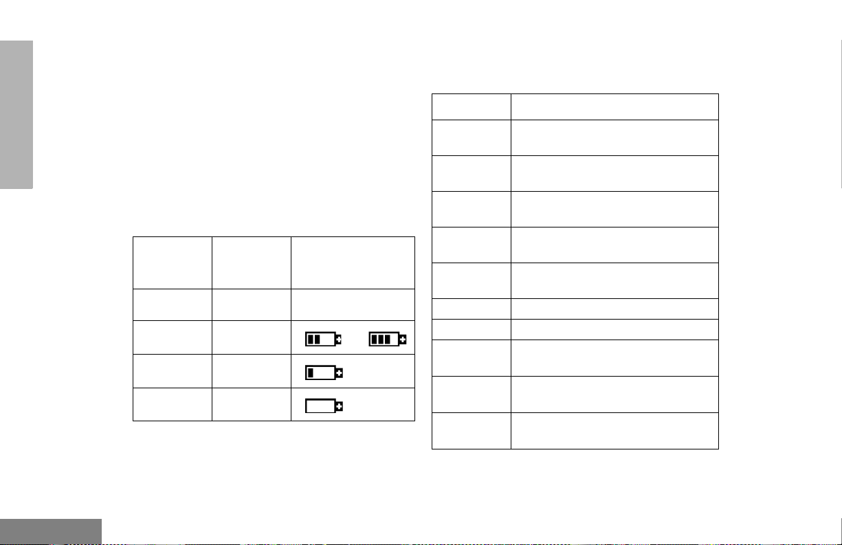
English
Indicates battery status (see page 24); or the
status of power-up, scan, or receipt of a
talkgroup or selective call as shown below:
LED Color Indicates
Steady red Your radio is transmitting (PTT
button pressed).
Flashing red Y our radio is attempting to access a
Trunked system (PTT button
pressed), or
Your radio is receiving (PTT button
released).
Double
flashing
yellow
12
Call Light feature activated, or
Individual Selective Call received
(Trunked operation only).
Push-to-Talk (PTT) Button
Press and hold down this button to talk; release
it to listen.
Microphone
When sending a message, hold the microphone
1 to 2 inches (2.5 to 5 centimeters) away from
your mouth, and speak clearly into it.
Menu Keys
Exit Up Menu/Select
(+ u
Left Down Right
<?>
Page 15

Menu/Select Key )
Used to enter Menu mode. When in Menu
mode, also used to make menu selections.
Exit Key (
Used to move to the previous menu level
(short press) or to exit Menu mode (long
press).
Up Key + and Down Key ?
• Used to scroll through the preprogrammed
talkgroups of a selected Trunked zone, or
through Conventional channels in a
Conventional zone.
Left Key <
Used as a backspace key when editing Radio
Call, Scan, and Phone lists. This key can also
be programmed to activate a radio feature (see
page 16).
Keypad Keys
123
456
789
*0#
RADIO OVERVIEW
• Used to scroll when in Menu mode.
• The ? key can also be programmed to
activate a radio feature (see page 16).
Right Key
Moves the cursor right or insert s a space when
editing Call, Scan, and Phone lists. This key
can also be programmed to activate a radio
feature (see page 16).
>
These keys are used to:
• Dial a phone number
• Enter a specific radio ID number when
making a Selective Call or Call Alert
• Enter information when programming Radio
Call, Scan and Phone lists
Each key can generate several different
characters. For example, to enter the character
“C,” press the 2 key three times. (Refer to
the table on the following page.)
13
English
Page 16

Entering Characters Using the Keypad
Number of Times Key is Pressed
RADIO OVERVIEW
Key
0
1
2
3
4
5
6
7
8
9
*
#
W
2
1
0
1
A
D
G
J
M
P
T
*
Blank
#
Space
34567891011 12 13 14 15
(
)<>
&
%# *
B
C2abc2БЗабз
E
F3def3ИЙКийк
H
I4ghi4Íìí
K
L5jkl5
N
O6mno6СУФтуфц
Q
RS7pqrs7
U
V8tuv8Úùú
X
YZ9wxyz9Yy
/
+-=
-.!?’”,;:
´
´
English
14
Page 17

Display
Symbol Indication
RADIO OVERVIEW
Call Received
The top two screen rows display menu and
radio status information:
Symbol Indication
A
X-Pand
B
Power Level
C
Monitor
D
Phone
The X-Pand feature is
activated. When in narrow
band, this feature improves
audio quality.
Low Power “ R ” or High
Power “ S ” is activated.
The selected channel is being
monitored (Conventional
operation only).
Phone mode is selected.
E
Emergency
F
Call Received
(LTR/Conv.)
Or
Incoming Call/
Page
(PassPort
Selective Call/
Call Alert)
G
Scan
An Emergency Siren is being
sounded or an Emergency
Alarm is being sent.
A Selective Call or Call Alert
has been received (LTR
trunked and Conventional
operation only).
A Selective Call or Call Alert
has been transmitted or
received. Flashing icon
indicates call attempt in
progress, while a solid icon
indicates that the call has been
established (PassPort
operation only).
When the green LED is
blinking, it indicates that the
System, PassPort Scan, or
All Group Scan feature has
been activated.
When the green LED is off, it
indicates that non-prioritized
Auto Group Scan has been
activated.
15
English
Page 18

Symbol Indication
Symbol Indication
RADIO OVERVIEW
Priority 1 Scan
(flashing)
•
H
Priority 2 Scan
( steady)
•
J
Talkaround
K
Programming
Mode
L
Keypad Lock
Indicates activity on a Priority
1 talkgroup or channel during
System Scan.
• When the green LED is on,
it indicates activity on a
Priority 2 talkgroup or
channel during System
Scan.
• When the green LED is off,
it indicates prioritized Auto
Group Scan has been
activated.
You are not transmitting
through a repeater
(Conventional operation
only).
A Program list is being edited.
The keypad is locked.
P
Battery Level
U
Clock
M
Signal Strength
N
PassPort Zone
The number of bars (0–4)
shown indicates the charge
remaining in your battery.
Shows the time (12- or
24-hour).
The more bars, the stronger
the signal being received by
your radio.
A PassPort zone has been
selected.
Programmable Buttons
Your dealer can program several of your
radio’s buttons as shortcuts to many of your
radio’s features.
Programmable buttons include:
• The three Side Buttons (A, B, C) and the
Top Button (D)
• The three Lower Menu Keys (P1, P2, P3)
(when your radio is not in Menu mode)
English
16
Page 19

Each button can be programmed to access up
to two features, depending on the type of
button press:
• Short Press—quickly pressing and
releasing the programmable buttons,
–or–
• Long Press—pressing and holding the
programmable buttons for a period of time
(programmable for 1/2 to 1 1/2 seconds),
–or–
• Hold Down—pressing and holding down
the programmable buttons while checkin g
status or making adjustments.
The table on page 18 summarizes the
programmable features available along with
the page number where the feature is
explained.
Ask your dealer to write down, in the “Button”
column, the names of the programmable
buttons next to the features that have been
programmed to them. Your dealer can use the
abbreviations shown in the radio illustration on
page 11 of this use guide (for example, A for
Side Button 1, D for Top Button, etc.). Your
dealer can also indicate whether the button
press is short press (SP) or long press (LP)
where applicable.
Contact your dealer for a complete list of
features available with your radio.
RADIO OVERVIEW
17
English
Page 20

Programmable Features
Feature Indicator Short Press Long Press Hold Down Page Button
Battery Gauge
LED
Color
Check the bat-
——
tery’s charge status.
24
RADIO OVERVIEW
Home Channel Revert
†
This feature is activated by EITHER a short OR a long press, but not both.
§
Conventional operation only. ‡LTR Trunked operation only. *PassPort Trunked operation only.
English
Edit Scan List —
Emergency
§†
Keypad Lock
Light
Message
Monitor
‡§
§
Phone
18
Add, delete or prioritize talkgroups and
channels.
E
Initiate Emergency
Alert
Cancel Emergency
Alert
Directly access your favorite Trunked
—
zone and talkgroup or Conventional chan-
†
nel.
Toggle the keypad
L —
between locked and
unlocked.
Turn on your radio’s backlight.
—
†
— Direct entry to the Message menu.
Exit Permanent
C
Monitor mode.
Directly access Phone mode.
D
Enter Permanent
Monitor mode.
†
66
—
57
32
—
——
——
†
—56
Continually
monitor channel
—
—
72
Page 21

Programmable Features
RADIO OVERVIEW
Feature Indicator Sh ort Press Long Press Hold Down Page Button
Power Level
Radio Call
‡§
B
LED Color
Toggle the transmit power level between
†
high and low.
Directly access the Radio Call menu.
†
—90
—51
Directly access one
Member Call
‡§
—
of the first 3
members of your
—
Radio Call List.
Speed Call
‡§
—
Display last entry called.
†
—51,
Toggle between using a Conventional
Repeater/Talkaround
J
repeater or transmitting directly to another
—31
§
radio.†
Manually initiate
Roam Request
Home Site Revert
Roam Lock
Selective Call
(Preprogrammed Button)
†
This feature is activated by EITHER a short OR a long press, but not both.
§
Conventional operation only. ‡L TR Trunked operation only. *PassPort Trunked operation only.
* Searching
PassPort roaming
function.
†
* Searching Turn Home Site Revert on.
* — Turn Roam Lock on or off.
*
LED Color Send a Selective Call.
Stop PassPort
roaming function. — 36
†
†
†
— 37
— 38
— 43
51,
53
53
19
English
Page 22

Programmable Features
Feature Indicator Short Press Long Press Hold Down Page Button
(Preprogrammed Button)
RADIO OVERVIEW
Scan/Delete Nuisance
†
This feature is activated by EITHER a short OR a long press, but not both.
§
Conventional operation only. ‡LTR Trunked operation only. *PassPort Trunked operation only.
Selective Call*
(One-Touch Button)
Call Alert*
Call Alert*
(One-Touch Button)
Channel
— Directly access the Radio Call List.
LED Color Send a Call Alert
†
— Directly access the Radio Call List.
G
Turn PassPort
Group, All Group,
and System scan
Delete a nuisance
channel while scanning.
on or off.
Display the PassPort site number on
Site/MIN View
* —
which the unit is registered, the Home Site
and unit’s Mobile Identification Number
†
(MIN).
Speed Dial — Quickly access the speed dial phone list.
Squelch
Status
§
‡§
Toggle the squelch level between tight
—
and normal.
†
— Directly access the Message menu.
†
—45
— 47
†
—48
—65
—35
†
—73
—90
†
—55
English
20
Page 23

Programmable Features
Feature Indicator Sh ort Press Long Press Hold Down Page Button
RADIO OVERVIEW
Voice Storage Record/
Playback
Voice Storage Playback
Exit
Voice Storage Playback
Delete
—
— Exit V oice Storage Play Back mode.
— Delete recorded messages.
Playback recorded
messages.
Record voice memos. — 81
†
†
— 81
—82
Sound a tone to
Volume Set — — —
adjust your
radio’s volume
level.
†
This feature is activated by EITHER a short OR a long press, but not both.
§
Conventional operation only. ‡L TR Trunked operation only. *PassPort Trunked operation only.
29
21
English
Page 24

RADIO OVERVIEW
AUDIO INDICATORS FOR
PROGRAMMABLE BUTTONS
In addition to having visual indicators, some
programmable buttons use tones to indicate
one of two modes:
High-Low To ne
Low-High To ne
Button High-Low Tone Low-High Tone
Scan Stop scan Start scan
Power Level
Squelch (no
visual indicator)
Keypad Lock Unlocked Locked
Repeater/
Talkaround
High power
selected
Normal squelch Tight squelch
Uses
Conventional
repeater
Low power
selected
Does not use
Conventional
repeater
English
22
Page 25

]
GETTING STARTED
LED Color Battery/Charger Status
GETTING STARTED
BATTERY INFORMATION
Charging the Battery
If a battery is new or its charge level is very
low, you need to charge it before use.
Note: Batteries are shipped uncharged from
the factory . Always charge a new battery
14 to 16 hours before initial use,
regardless of the status indicated by the
charger.
To charge the battery, place the battery, with or
without the radio, in the charger. The charger
LED indicates the charging progress:
LED Color Battery/Charger Status
No LED indication Battery inserted incorrectly.
Single green flash Successful charger power-up.
Flashing red* Battery is not chargeable or
not making proper contact.
Steady red Battery in rapid-charge mode.
Flashing yellow Battery in charger, not in
rapid-charge mode but waiting to
be charged.
†
Flashing green
Steady green Battery fully charged.
* Remove the battery from the charger. Clean the
battery contacts with isopropyl alcohol applied to
a soft cloth. Place the battery back in the charger.
If the LED indicator continues to flash red,
replace the battery.
† A standard battery may require one hour to
charge to 90%.
Battery 90% (or more)
charged.
23
English
Page 26
GETTING STARTED
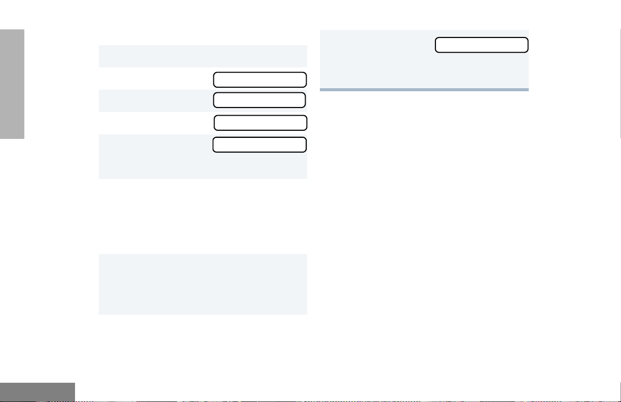
Battery Charge Status
You can check your battery’s charge status in
two ways:
• The charge status is shown by the P
status indicator symbol on the display. This
symbol is shown automatically.
• Hold down the preprogrammed Battery
LED Indicator button (see page 16). The
charge status is shown by the color of your
radio’s LED indicator.
Battery
Level
High Green
Sufficient Yellow
Low Flashing red
Very Low None
LED
Indicator
Status Indicator
P
P
or
(flashing)
Battery chargers will only charge the Motorolaauthorized batteries listed below. Other
batteries may not charge.
Part No. Description
HNN9008 1500 mAH NiMH High-Capacity
Battery (standard)
HNN9009 1900 mAH NiMH Ultra-High-
Capacity Battery
HNN9010 1800 mAH NiMH, Ultra-High-
Capacity - Factory Mutual
HNN9011 1200 mAH Ni-CD, High-Capacity
Battery - Factory Mutual
HNN9012 1300 mAH Ni-CD High-Capacity
Battery
HNN9013 1200 mAH Lithium Ion Battery
HPNN4045 1200 mAH NiMH, 7.5 V Battery
HNN4001
HNN4002
HNN4003
TM
Impres
Battery
Impres
Battery - Intrinsically Safe (FM)
Impres
Battery
1900 mAH NiMH, 7.5 V
TM
1800 mAH NiMH, 7.5 V
TM
2000 mAH Li-ion, 7.5 V
English
24
Page 27

Attaching the Battery Removing the Battery
2
1
GETTING STARTED
Battery Latches
2
3
1 Fit the extensions at the bottom of the battery
into the bottom slots on your radio.
2 Press the top part of the battery toward your
radio until you hear a click.
1 Turn off your radio (see page 28).
2 Slide both battery latches downward.
3 Pull the top part of the batter y away f rom yo ur
radio.
25
English
Page 28

GETTING STARTED
ACCESSORY INFORMATION
Attaching the Antenna
Removing the Antenna
English
Turn the antenna clockwise to attach it.
26
Turn the antenna counterclockwise to
remove it.
´
´
Page 29

Attaching the Belt Clip Removing the Belt Clip
Belt Clip Tab
1
2
GETTING STARTED
1 Align the grooves of the belt clip with those of
the battery.
2 Press the belt clip downward until you hear a
click.
1 Use a key to press the belt clip tab away from
the battery.
2 Slide the belt clip upward to remove it.
27
English
Page 30

GETTING STARTED
Attaching the Side Connector Cover
Antenna
Loop
Slot
TURNING YOUR RADIO ON OR OFF
ON OFF
English
Thumbscrew
1 Place the loop (attached to the side connector
cover) over the antenna; then slide it
downward until it touches the top of the radio.
2 Insert the tab on the top of the cover into the
slot above the connector.
3 Position the cover over the connector and
align the thumbscrew with the threaded hole
in the radio.
4 Tighten the thum bscrew to hold the cover in
place. Do not overtighten the thumbscrew.
28
Turn the On/Off/
Volume knob clockwise.
If power-up is
successful, you hear a
Self-Test Pass Tone
and see the LED
momentarily turn green.
If your radio fails to
power up, you hear a
Self-Test Fail
Tone
.
Turn the On/Off/
Volume knob
counterclockwise
until you hear a click.
Page 31

ADJUSTING THE VOLUME
To select a Trunked zone and Talkgroup:
GETTING STARTED
Turn the On-Off/Volume Control knob
clockwise to increase the volume or
counterclockwise to decrease the volume.
–or–
1 Hold down the Volume Set button (se e
page 21); you hear a continuous tone.
2 Turn the On-Off/Volume Control knob to the
desired volume level.
3 Release the Volume Set button.
SELECTING A TRUNKED ZONE AND
TALKGROUP
Up to 15 PassPort and/or LTR trunked zones
(containing 16 talkgroups each) can be
programmed into your radio.
1 Use the Zone Selector knob to select the
appropriate Trunked zone.
2
+ or ? until you see the desired
preprogrammed talkgroup on the display.
Note: The display shows N (the PassPort
Zone symbol) when a PassPort Zone
is selected.
SENDING A TRUNKED CALL
To send a T r unked call:
1 Hold your radio in a vertical
position at a distance of about 1
to 2 inches (2.5 to 5 centimeters)
from your mouth.
29
English
Page 32

GETTING STARTED
2 Press and hold the PTT button.
–or–
Press and release the PTT button and wait
three seconds.
• If access to the Trunked system is
successful, the LED indicator lights steady
red.
In addition, your dealer can program
your radio to sound a short, high-pitched
(talk permit) tone, indicating successful
Trunked system access.
• If access to the Trunked system was
unsuccessful, the LED indicator flashes red
and a low-pitched (talk prohibit) tone
sounds, indicating that the system was
busy or out of range.
3 With the PTT button depressed, speak clearly
into the microphone.
4 Release the PTT button to listen.
You will see the Alias (if preprogrammed) or
MIN of the calling radio on your radio’s disp l ay.
SELECTING A CONVENTIONAL
ZONE AND CHANNEL
Up to a total of 16 conventional channels, in one
or more conventional zones, can be
programmed into your radio as follows:
1 Use the Zone Selector knob to select the
appropriate Conventional zone.
2 + or ? until you see the desired
Conventional channel on the display.
SENDING A CONVENTIONAL CALL
Note: In the United States, FCC regulations
require you to monitor the Conventional
channels before sending a call. The
Monitor feature (see page 16) can be
accessed through one of your
programmable buttons (if progra m m ed
by your dealer).
1 Hold your radio in a vertical
position at a distance of about 1
to 2 inches (2.5 to 5
centimeters) from your mouth.
English
30
Page 33

2 Press the PTT button and speak clearly into
the microphone. The LED indicator lights
steady red while the call is being sent.
3 Release the PTT button to listen.
RECEIVING A TRUNKED OR
CONVENTIONAL CALL
REPEATER OR TALKAROUND J
MODE
Note: This feature is available only with
Conventional operation.
Talkaround mode enables you to communicate
with another radio when:
• The repeater is not operating
GETTING STARTED
–or–
1 Turn your radio on.
2 Adjust your radio’s volume (see page 29).
• Your radio is ou t of the repeater’s range, but
within communicating distance of another
radio.
3 Use the Zone Selector knob to select the
desired Trunked or Conventional zone. Make
sure the PTT button is released.
4 Listen for voice activity. The LED indicator
flashes red when your radio is receiving.
Note: The Mobile Identification Number
(XXXX) or Alias (if preprogrammed) of
the calling radio appears on the
display if Caller ID is enabled.
XXXX
Note: The display shows J when Talkaround
mode is selected.
To select Repeater or Talkaround mode:
Press the preprogrammed Repeater/
Talkaround button (see page 16) to toggle
between Repeater and Talkaround mode.
–or–
1
) to enter Menu mode.
2
+ or ? until
3
) to select
Rptr/Talkarnd
Rptr/Talkarnd
31
English
Page 34

GETTING STARTED
4
+ or ? until
or until
5
) to confirm your selection.
Rptr/Talkarnd
Talkarnd Mode
CALL LIGHT
(TRUNKED OPERATION ONLY)
The Call Light indicator informs you that you
have received a call from a specified talkgroup
(as programmed by your dealer). The yellow
LED indicator will flash continuously, indicating
that a Trunked call has been received.
To turn the Call Light off, do one of the
following:
• Press the PTT button.
• Select another Trunked or Conventional
zone.
• Press any preprogrammed button.
• Turn your radio off, and then on again.
HOME CHANNEL REVERT
The Home Channel Revert feature allows you
to instantly access your favorite Trunked
talkgroup or Conventional channel at the touch
of a button.
To activate Home Channel Revert:
Press the preprogrammed Home Channel
Revert button (see page 18).
English
32
Page 35

PASSPORT TRUNKING
you with optimal audio quality throughout your
communications.
PassPort® is an enhanced, wide-area trunking
protocol developed by Trident Micro Systems.
Up to 128 Trunked sites can be linked together
to form one PassPort system, which means
that your communications can extend far
beyond the reach of a single trunked site.
SEAMLESS ROAMING
PassPort Trunking systems offer you the ability
to seamlessly roam among all sites in a
network. Seamless Roaming means that you
do not have to manually change the zones on
your radio when roaming from site to site. As
you roam throughout a PassPort System’s
coverage area, your HT1250•LS+ radio
regularly monitors the RSSI (Received Signal
Strength Indication) level of the site on which
you are currently registered. In addition, if the
signal strength falls below the acceptable
threshold preprogrammed by your dealer, your
radio starts monitoring the RSSI level of
adjacent sites within the network. This allows
the HT1250•LS+ radio to quickly roam to the
site with the strongest signal, which provides
Initial Registration
Your HT1250•LS+ radio needs to register on
the PassPort system before communication
with your talkgroup can begin. Registration
automatically takes place upon radio power up
or after selecting the desired PassPort zone on
the selector knob unless your radio is Site
Restricted from that site or Group Restricted
from that talkgroup. What you see:
1 Upon radio Power up,
you see:
(if you select a
PassPort zone after
your radio has
powered up, see step
2).
2 The display shows
the selected
PassPort Zone Alias
(if preprogrammed).
PassPort
ZONE ALIAS
PASSPORT
TRUNKING
33
English
Page 36

TRUNKING
PASSPORT
3 The display shows
the selected
Talkgroup Alias (if
preprogrammed).
Note: If your radio performs a more extensive
frequency search in order to attempt
registration, you may
see:
4 Upon successful
PassPort
Registration, you see:
Note: Your radio sounds a “Low-High” tone
upon successful PassPort System
registration. XXX is a number that
indicates the site within the PassPort
system on which you have registered.
5 After successfully
registering to a site,
the selected PassPort
talkgroup alias
appears and remains
on the display.
TLKGRP ALIAS
SEARCHING
REG SITE XXX
TLKGRP ALIAS
Roaming and Registering between Sites
Once initial registration with the PassPort
system has occurred, your radio constantly
monitors the RSSI to ensure an acceptable
signal level is maintained (as programmed by
your dealer). When the RSSI in your radio fa lls
below this acceptable level, your HT1250•LS+
radio attempts to roam to and register onto
another site within the PassPort system.
This process happens automatically and
requires no action on your part. What you see:
1 When your radio is
searching for a new
site or attempting
successful
registration to a site,
or if the radio roams
to a restricted site,
you see:
Note: This message is displayed until
registration occurs. For more
information about site restriction,
please contact your dealer.
SEARCHING
English
34
Page 37

2 When your radio has successfully registered
to a new site in the PassPort
System, XXX indicates the site number you
see:
Note: You will not see this if your radio is Site
Restricted from the site it is trying to
access.
3 The selected PassPort talkgroup alias
appears and remains
on the display.
Note: If the radio is
set to a
restricted talkgroup, you
see:
For more information about Site and
Group Restriction, see page 39.
REG SITE XXX
TLKGRP ALIAS
GrpRestrict
SITE/MIN VIEW
There may be circumstances when you want to
view the number of the PassPort site on which
you are registered as well as your Mobile
Identification Number (MIN) of your
HT1250•LS+ radio.
To Start and Stop Viewing Site/MIN:
1 Press the preprogrammed SITE/MIN View
button (see page 16).
The display shows
the number of the site
on which you are
currently registered.
Note: If the preprogrammed button is
activated prior to or during registration,
a bad key chirp is sounded and you
see
The display indicates the Home Site ID
(HSID) and Mobile Identification Number
(MIN). XXX indicates the HSID, YYYYY
indicates the
MIN.
site now XXX
site now n/a
IAM XXX-YYYYY
PASSPORT
TRUNKING
35
English
Page 38

TRUNKING
PASSPORT
Note: This message can still be activated
even if your radio is not registered.
PTT ID ALIAS
Your HT1250•LS+ radio supports the display of
the Alias of the calling radio when receiving a
group dispatch call in PassPort mode. This
Alias corresponds to the MIN of the calling
radio in the Radio Call List.
Note: Alias will be displayed only if
preprogrammed in the radio via the
PassPort Customer Programming
Software (PPCPS). Otherwise, the
MIN is displayed.
ROAM REQUEST
Since your radio has the RSSI feature, your
HT1250•LS+ radio automatically roams to an
affiliated site when the signal from the
registered site becomes too weak for quality
communication. This RSSI threshold is
programmed by your dealer. However, if you
believe the signal strength would be better on
another site, you may want to manually initiate
the roaming process. This feature is called
Roam Request.
To Start a Roam Request:
Press the preprogrammed Roam Request
1
button (see page 16).
When your radio is searching for a new site or
2
attempting registration to a site, you
see:
When your radio has successfully registered to
3
the new site on the PassPort System,
you see:
–or–
SEARCHING
REG SITE XXX
English
36
Page 39

A bad key chirp may sound and you
see:
Roam Not Avail
To Cancel a Roam Request:
Press and hold the preprogrammed Roam
Request button (see page 19) again.
This can occur under the following
circumstances:
• When registration to a site with a higher
RSSI than your current site is unavailable.
• When the preprogrammed button is
pressed before your radio has collected its
“neighbor list”. A “neighbor list” is a list of
frequencies from adjoining sites within the
PassPort system that are used during the
roam process.
• When your radio is programmed for a
single site system (Home Site only).
In these cases, wait a few seconds and try
again.
4 The selected
PassPort talkgroup
alias appears and
remains on the
display.
TLKGRP ALIAS
You see:
Note: Your radio then attempts to return to
the previously registered site.
Cncl Roam Req
HOME SITE REVERT
This feature allows you to force a HT1250•LS+
radio to search for its home site and register on
it while the radio is currently registered on an
affiliated site.
Press the preprogrammed Home Site Revert
1
button (see page 19).
When the radio is
2
searching for a new
site or attempting
registration to a site,
you see:
SEARCHING
PASSPORT
TRUNKING
37
English
Page 40

TRUNKING
PASSPORT
When the radio has
3
successfully registered to its PassPort
home site, you see:
• The radio sounds a “Low-High” tone upon
successful PassPort System registration.
The XXX number indicates the site within
the PassPort system on which you have
registered.
Note: If the radio is already registered on its
home site and Home Site Revert is
initiated, a bad key chirp is sounded.
4 After successfully
registering on the
home site, the
selected PassPort
talkgroup alias
appears and remains
on the display.
Notes:
• The radio must currently be registered on
an affiliated site.
• If the radio cannot register to its Home Site
for any reason, the radio reverts back to its
current affiliated site.
REG SITE XXX
TLKGRP ALIAS
ROAM LOCK
Because of the RSSI (Received Signal
Strength Indication) feature, the HT1250•LS+
radio automatically roams to a different site
when the signal falls below the RSSI level
programmed in your radio by your dealer. In
some instances (inside a building or in fringe
areas), you may want to prevent your radio
from roaming. This is possible by enabling the
Roam (Site) Lock function.
Note: If you are currently on an affiliated site and
wish to lock onto your home site, you need
to first press the preprogrammed Home Site
Revert button prior to pressing the preprogrammed Roam Lock button.
To Activate Roam Lock
Press the preprogrammable Roam Lock but-
1
ton (see page 19).
English
38
Page 41

2 You see.
Alternating with:
at one second intervals.
• A good key chirp is heard.
Note: A radio can be roam-locked only
when it is registered to a site.
TLKGRP ALIAS
Roam Locked
To Deactivate Roam Lock
To cancel Roam Lock, either press the
preprogrammable Roam Lock button again or
turn off your radio or switch zones/talkgroups.
Your radio automatically re-registers onto the
PassPort system.
Note: Once deactivated, the radio follows the
roaming criteria programmed in the radio.
PASSPORT PRIMARY TALKGROUP
This is the first talkgroup preprogrammed in
your list. Per definition, it always has the
highest-level priority among all other
preprogrammed talkgroups, also called
secondary talkgroups. As such, any
transmission on the primary talkgroup is heard
on all other idle talkgroups regardless of where
the radio is registered (home or affiliated sites).
In addition, a user can respond to a call on the
primary talkgroup simply by pressing the PTT
button within a preprogrammed period of time.
If you prefer to use the primary talkgroup for
“announcement” calls, you can disable the
transmit function. In addition, if you do not have
a need for a primary talkgroup, it is possible to
disable the level of priority of this talkgroup in
the programming software.
Note: Please contact your local dealer for addi-
tional information.
SITE / TALKGROUP RESTRICTION
(Access Privileges by MIN)
The HT1250•LS+ portable radio offers two
“access privilege” features called Site and
Talkgroup Restriction. These features,
however, can only be enabled or disabled
through the PassPort infrastucture (if the
PASSPORT
TRUNKING
39
English
Page 42

TRUNKING
PASSPORT
Access Privileges by MIN option is available).
These features allow the radio to register and
operate normally on the home site and on
specific affiliated sites or talkgroups which are
not restricted as programmed at the
infrastructure level by the system operator.
Note: All sites except the Home Site can be site
and/or talkgroup restricted.
Site Restriction
The registration and roaming process is
unaffected for "non-restricted" radios. However,
when a radio is site-restricted from a certain
affiliated site in the system, it is prohibited from
registering on that site and immediately tries to
register to its home site. If the radio is unable to
register on the home site, the radio moves on
to the next frequency (in its neighbor list of
sites) and attempts to register there.
What you see:
then:
Until successful registration to its home
site or a non-resistricted affiliated site.
–or–
If the radio does not
support this feature
or the system does
not receive an
acknowledgement
message from the
radio. You see:
Note: If your radio is disabled, power it
down and contact your local dealer.
For additional information about site/
talkgroup restriction, please contact
your local dealer.
Searching
Disabled
English
For 3 seconds:
40
SiteRestrict
Page 43

Group Restriction
TROUBLESHOOTING
The registration and roaming process is
unaffected for "non-restricted" radios. However,
when a radio is talkgroup-restricted from all
unrestricted affiliated sites in the system
(except the home site where it is always
available), it is not able to register on that
talkgroup. In this case you have to either switch
talkgroups within the same site or roam to the
home site (via the Home Site Revert feature) or
initiate a Roam Request to a different talkgroup
on an affiliated site.
You see:
If you subsequently
initiate a roam
request to the home
site or to a different
talkgroup on an affiliated site, you see:
GrpRestrict
Searching
While in PassPort zones, your radio may
display specific messages to indicate you
should contact your dealer for assistance.
Message What it Means
“Invalid Group
ID”
“DISABLED” Your radio requires reactivation
Blank display
upon power up
with a fully
charged battery.
Your dealer needs to verify
talkgroup programming in your
radio or the PassPort system.
on the PassPort system (not
applicable to Conventional and
LTR functionality).
Y our radio needs to be returned
to your dealer for reactivation or
service.
PASSPORT
TRUNKING
41
English
Page 44

TRUNKING
PASSPORT
Notes:
English
42
Page 45

PASSPORT SIGNALING
Sending a Selective Call using the
Preprogrammed Button
Selective Call and Call Alert are available in
the HT1250•LS+ radio using the PassPort
protocol. As such, no third party can hear the
conversation of two users engaged in a
Selective Call. Selective Call and Call Alert are
mutually exclusive. If one of the users is
engaged in a Selective Call or Call Alert while
roaming to a different site, the Selective Call or
Call Alert will end.
SELECTIVE CALL
You can initiate a Selective Call to a particular
radio in three different ways:
• Using a preprogrammed button.
• Through the menu.
• Using the One-Touch button.
• Press the preprogrammed Selective Call
button (see page 19). Proceed to Step 4.
–or–
Sending a Selective Call through the Menu
1 ) to enter menu mode.
2 + or ? until
3 ) to select
• The LED indicator lights a steady yellow.
• The display shows
grammed alias or ID of the last active
Selective Call is displayed.
4 If the unit has not
been engaged in a
Selective Call after
power-up, you see:
Selective Call
Selective Call
F and the prepro-
Select User
+ or ? to locate the desired alias or ID
in the Radio Call List.
SIGNALING
PASSPORT
43
English
Page 46

PASSPORT
SIGNALING
–or–
+ or ? then press the first letter of the
desired alias using the DTMF keys to start an
alphabetical search. (Full keypad model only.)
–or–
Enter the ID number of the radio you wish to
call. (Full keypad model only.)
–or–
Press * and the DTMF key (0 to 9) (if programmed by your dealer) corresponding to
the radio you wish to call.
Note: This option does not require you to
press the PTT button to send the
Selective Call.
5 Press the PTT button to send the Selective
Call.
• While the Selective Call is being estab-
lished the F blinks and the LED indicator
flashes red momentarily.
• A talk permit tone sounds.
6 Once the Selective Call is received and
acknowledged by the target radio, the
plays solid.
Notes:
• If the Selective Call cannot be established,
you see:
for 5 seconds. The LED indicator turns off.
• If all channels are busy while attempting a
Selective Call,
you see:
and will hear a delayed busy tone as long
as the PTT button is pressed.
If the PTT button is kept pressed and the
system frees up a channel, the radio automatically attempts to re-establish the call.
• ( to end the Selective Call and revert to
talkgroup dispatch, or press the preprogrammed Selective Call button. You can
then manually re-initiate the call. (See Step
1.)
No Acknowledge
System Busy
F dis-
English
44
Page 47

7 Press the PTT button to talk; release to listen.
8 ( to end the Selective Call.
Note: If the Selective Call has prematurely
ended,
you see:
and a tone sounds (if preprogrammed by your dealer).
Call Ended
Sending a Selective Call using the OneTouch Button
3 • While the Selective Call is being estab-
lished the
flashes red momentarily.
• Once the Selective Call is established the
F blinks and the LED indicator
F displays solid.
Notes:
• If preprogrammed by your dealer, your
radio sounds a short high-pitched tone (call
established tone) to indicate that you are
ready to engage in a conversation.
• If the Selective Call cannot be established,
you see:
No Acknowledge
1 Press and hold the preprogrammed One-
Touch button.
• The LED indicator lights a steady yellow.
• The display shows
grammed alias or ID is displayed.
2 The Selective Call is sent automatically.
F and the prepro-
for 5 seconds. The LED indicator turns off.
• If all channels are busy while attempting a
Selective Call,
you see:
System Busy
45
SIGNALING
English
PASSPORT
Page 48

and will hear a delayed busy tone as long
as the PTT button is pressed.
If the PTT button is kept pressed and the
system frees up a channel, the radio automatically attempts to re-establish the call.
•
( to end the Selective Call and revert to
talkgroup dispatch, or press the preprogrammed Selective Call button. You can
then manually re-initiate the call. (See Step
1.)
4 Press the PTT button to talk; release to listen.
5 ( to end the Selective Call.
Note: If the Selective Call has prematurely
ended,
Receiving a Selective Call F
1 When you receive a Selective Call:
• The F blinks and, if preprogrammed by
your dealer, the LED indicator lights steady
yellow.
You see:
followed by the preprogrammed alias or ID
of the calling radio.
• Once the Selective Call is established the
Incoming Call
F displays solid.
Note: If preprogrammed by your dealer,
your radio sounds a short highpitched tone (call established tone)
to indicate that you are ready to
engage in a conversation.
PASSPORT
SIGNALING
English
46
you see:
and a tone sounds (if preprogrammed by your dealer).
Call Ended
2 To answer the Selective Call, press the PTT
button to talk; release to listen.
3 ( to end the Selective Call.
Note: If the Selective Call has prematurely
ended,
you see:
and a tone sounds (if preprogrammed by your dealer).
Call Ended
Page 49

CALL ALERT
You can alert another person by sending a Call
Alert to a particular radio in three different
ways:
If the unit has not
4
been engaged in a
Call Alert after
power-up, you see:
Select User
• Using a preprogrammed button.
• Through the menu.
• Using the One-Touch button.
Sending a Call Alert using the
Preprogrammed Button
• Press the preprogrammed Call Alert button
(see page 20). Proceed to Step 4.
Sending a Call Alert through the Menu
1 ) to enter menu mode.
+ or ? until
2
3 ) to select
• The LED indicator lights a steady yellow.
• The display shows
grammed alias or ID of the last active Call
Alert is displayed.
Call Alert
Call Alert
F and the prepro-
+ or ? to locate the desired alias or ID
in the Radio Call List.
–or–
+ or ? then press the first letter of the
desired alias using the DTMF keys to start an
alphabetical search. (Full keypad model only.)
–or–
Enter the ID number of the radio you wish to
page. (Full keypad model only.)
–or–
Press * and DTMF key (0 to 9) (if programmed
by your dealer) corresponding to the radio you
wish to page.
Note: This option does not require you to
press the PTT button to send the
Call Alert.
47
SIGNALING
English
PASSPORT
Page 50

PASSPORT
SIGNALING
5 Press the PTT button to send the Call Alert.
• While the Call Alert is being established
F blinks and the LED indicator flashes
the
red momentarily.
6 Once the Call Alert is
received and
acknowledged by the
target radio, the
displays solid and
you see:
Notes:
• If the Call Alert cannot be established,
you see:
for 5 seconds. The LED indicator turns off.
• If all channels are busy while attempting a
Call Alert,
you see:
F
Acknowledge
No Acknowledge
System Busy
and will hear a delayed busy tone as long
as the PTT button is pressed.
If the PTT button is kept pressed and the
system frees up a channel, the radio automatically attempts to re-establish the call.
( to end the Call Alert and revert to
•
talkgroup dispatch, or press the preprogrammed Call Alert button. You can then
manually re-initiate the call. (See Step 1.)
( to end the Call Alert.
7
Sending a Call Alert using the One-Touch
Button
1 Press and hold the preprogrammed One-
touch button.
• The LED indicator lights steady yellow.
• The display shows
grammed alias or ID is displayed.
2 The Call Alert is sent automatically.
• The LED indicator lights steady red.
Note: Your radio sounds a continuous tone
(if programmed by your dealer).
F and the prepro-
English
48
Page 51

3 • While the Call Alert is being established
the
F blinks and the LED indicator flashes
red momentarily.
• Once the Call Alert is established the
displays solid.
Notes:
• If preprogrammed by your dealer, your
radio sounds a short high-pitched tone
(page established tone) to indicate that the
page was successful.
If the Call Alert cannot be established,
F
and will hear a delayed busy tone as long
as the PTT button is pressed.
If the PTT button is kept pressed and the
system frees up a channel, the radio automatically attempts to re-establish the call.
( to end the Call Alert and revert to
•
talkgroup dispatch, or press the preprogrammed Call Alert button. You can then
manually re-initiate the call. (See Step 1.)
( to end the Call Alert.
4
you see:
for 5 seconds. The LED indicator turns off.
• If all channels are busy while attempting a
Call Alert,
you see:
No Acknowledge
System Busy
Receiving a Call Alert F
1 When you receive a Call Alert:
•The F blinks and, if preprogrammed by
your dealer, the LED indicator lights steady
yellow.
You see:
Incoming Page
49
SIGNALING
English
PASSPORT
Page 52

PASSPORT
SIGNALING
followed by the preprogrammed alias or ID
of the calling radio.
• Once the Call Alert is established the F
displays solid.
Note: If preprogrammed by your dealer,
your radio sounds a short highpitched tone (page established) to
indicate that the page was successful.
2 To answer the Call Alert, press the PTT button
to talk; release to listen.
3 ( to end the Call Alert.
English
50
Page 53

RADIO CALLS
You see:
Name xxxx
RADIO CALLS
Note: Available in LTR and Conventional
modes only based on model feature set
of your HT1250•LS+ radio. Please
check with your dealer.
In LTR Trunked mode, Radio Call
features are available only if the system
is available.
MAKING A SELECTIVE CALL
You can make a Selective Call to a particular
radio or to a group of radios, as programmed
by your dealer.
To Make a Selective Call
Press the preprogrammed Radio Call button
(see page 19), and proceed to step 4 on page
52.
–
or–
1 Press the preprogrammed Member Call
button corresponding to the member you wish
to call.
alternating with:
Note: For DTMF radio models, if you press
any digit on the keypad (#1-9), the
display shows the corresponding
entry from the Radio Call List.
2 Proceed to step 7 on page 52.
Selective Call
–or–
1 Press the preprogrammed Speed Call button.
You see the Alias (if
preprogrammed) or
ID of the last called
entry.
Note: For DTMF radio models, if you press
any digit on the keypad (#1-9), the
display shows the corresponding
entry from the Radio Call List.
2 Proceed to step 7 on page 52.
Name xxxx
51
English
Page 54
–or–
1 ) to enter Menu mode.
9 ( to return to
–or–
Selective Call
RADIO CALLS
2 + or ? until
3 ) to select
4 + or ? until
5 ) to select
The LED lights a steady yellow
6 + or ? to locate the desired ID in the
Radio Call list.
–or–
Enter the ID number of the radio you want to
call (full keypad models only).
7 Press the PTT button to send the call.
• Y our radio sounds a continuous tone (if
programmed by your dealer) and the LED
lights a steady red.
8 Press the PTT button and talk; release the
PTT button to listen.
Radio Call
Radio Call
Selective Call
Selective Call
Hold down ( to exit Menu mode.
RECEIVING A SELECTIVE CALL F
When you Receive a Selective Call
• The display shows F and the
preprogrammed name or ID of the calling
radio.
• The LED flas he s yello w (if pr ogr am m ed by
your dealer).
• You hear an alert tone.
To answer the call, press the PTT button.
Note: In L TR T runked mode, unless you make
a Selective Call back to the caller within
the preprogrammed time, your response
is heard by all members of your
talkgroup.
English
52
Page 55

SENDING A CALL ALERT PAGE
Y ou can alert an other person by sending a Call
Alert page.
To Send a Call Alert Page
Press the preprogrammed Radio Call button
(see page 19) and proceed to step 4:
–
or–
1 Press the preprogrammed Member Call
button corresponding to the member you wish
to call.
–or–
1 Press the preprogrammed Speed Call button.
You see the Alias (if
preprogrammed) or
ID of the last called
entry.
Note: For DTMF radio models, if you press
any digit on the keypad (#1-9), the
display shows the corresponding
entry from the Radio Call List.
Name xxxx
RADIO CALLS
You see:
alternating with:
Note: For DTMF radio models, if you press
any digit on the keypad (#1-9), the
display shows the corresponding
entry from the Radio Call List.
2 Proceed to step 7 on page 54.
Name xxxx
Call Alert
2 Proceed to step 7 on page 54.
–or–
1 ) to enter Menu mode.
2 + or ? until
3 ) to select
4 + or ? until
5 ) to select
The LED lights a steady yellow.
Radio Call
Radio Call
Call Alert
Call Alert
53
English
Page 56

RADIO CALLS
6 + or ? to locate the desired ID in the
Radio Call list.
–or–
Enter the ID number of the radio you want to
page.
7 Press the PTT button.
The display alternately
shows
and the preprogrammed name or ID.
The LED lights a steady yellow and then
flashes red every time your radio attempts to
transmit the call.
8 If the Call Alert page is received by the target
radio, you see
If the page was not
received, you see
The radio sounds a
short alert tone.
Call In Prog
Acknowledge
No Acknowledge
Hold down ( to exit Menu mode.
RECEIVING A CALL ALERT PAGE F
When you receive a Call Alert Page:
Call Received
• The display shows
and the preprogrammed name or ID of the
calling radio.
• You hear four alert tones, either once or
continuously, as programmed by your
dealer.
• The LED flashes a single yellow for a group
call, or flashes a double yellow for an
individual call.
To answer the page, press the PTT button; to
cancel the page, press any other key.
Note: Your radio displays only the last Call
Alert page received. In addition, your
radio does not receive any future
Selective Calls until you clear the page.
F,
English
9 ( to return to
–or–
54
Call Alert
Page 57

RADIO CHECK
Radio Check allows you to determine if a radio
is within the range of the Trunked or
Conventional system and turned on, without
disturbing the user of that radio. This feature
can also be used when attempts with Selective
Call and Call Alert fail.
To perform a Radio Check
1 ) to enter Menu mode.
2 + or ? until
:
Radio Call
You see
8 If the Radio Check is received by the target
radio, you see
If the Radio is not received,
you see
9 ( to return to
–or–
Hold down ( to exit Menu mode.
Call In Prog
Acknowledge
No Acknowledge
Radio Check
RADIO CALLS
3 ) to select
4 + or ? until
5 ) to select
6 + or ? to locate the desired ID in the
Radio Call list.
–or–
Enter the ID number of the radio you are
checking.
7 Press the PTT button.
Radio Call
Radio Check
Radio Check
SENDING A STATUS
This feature gives you the ability to send a
status update to the base. The Status feature
makes more efficient use of the channel
compared to voice transmissions. You dealer
can program your radio with status updates of
up to 14 characters.
To send a Status
1 ) to enter Menu Mode.
y or z until
2
:
Status
55
English
Page 58

RADIO CALLS
3 ) to select
4 y or z to locate the desired status in the
preprogrammed list.
–or–
when using the enhanced keypad microphone
only, enter the number of the status you wish
to send.
–or–
if programmed by your dealer (see page 20),
press the button that has been
preprogrammed for a specific status.
Note: You cannot retransmit the current
status update.
5 Press the PTT button.
You see:
Status
Update In Prog
Note: If the radio is not able to send the
status or does not receive an
acknowledgement if one is expected,
you see
If the radio is not able to send the
status and no acknowledgement is
expected,
you see
No Acknowledge
No Channel
SENDING A MESSAGE
This feature gives you the ability to send and
receive preprogrammed messages. Data
messages make more efficient use of channels
compared to voice transmissions. Your dealer
can program your radio with messages of up to
14 characters.
To send an Electronic (Data) Message
1 ) to enter Menu mode.
:
English
56
2 y or z until
3 ) to select
Message
Message
Page 59

4 y or z to locate the desired message in
the preprogrammed list.
–or–
when using the enhanced keypad microphone
only, enter the number of the message you
wish to send.
–or–
if programmed by your dealer (see page 18),
press the button that has been
preprogrammed for a specific message.
Note: You cannot re-transmit the current
message update.
5 Press the PTT button.
You see
Msg In Prog
RECEIVING A MESSAGE
When your radio receives a message:
• You hear two alert tones.
• The yellow LED indicator flashes.
• The display alternately
shows
and the preprogrammed alias.
Note: If you receive a message that is not
programmed into your radio, the display
alternately shows the
following:
Msg Received
Message #_
No Alias
RADIO CALLS
Note: If the radio is not able to send the
message or the radio does not
receive an acknowledgement if an
one is expected,
you see
No Acknowledge
If the radio is
not able to send the message and
no acknowledgement is expected,
you see
No Channel
SENDING AN EMERGENCY ALERT E
(CONVENTIONAL AND LTR MODES ONLY)
In the event of an emergency, you may need to
quickly get the attention of others for help. The
Emergency Alert feature, if programmed by
your dealer, causes your radio to send a
priority Emergency Alert (see page 18) to a
specific radio or dispatch center.
The display shows E when your radio is in the
Emergency Alert state.
57
English
Page 60

RADIO CALLS
Note: In Conventional mode, Emergency Alerts
have priority over all other calls.
An Emergency Alert can be programmed to do
one of the following:
•show E and sound a tone
–or–
•show E (silent Emergency)
–or–
• activate the microphone so that all activity
can be transmitted (for a predetermined
amount of time).
To activate Emer g en cy Alert, pr ess the
preprogrammed Emergency button.
To cancel Emergency Alert, press and hold the
preprogrammed Emergency button, or press
the PTT button.
EDITING A RADIO CALL LIST K
Y our radio has a Radi o Call list that contains the
names and radio IDs of several talkgroups or
individuals. The ID numbers in the Radio Call
List are programmed by your dealer, and
cannot be changed from your radio. However,
you can edit the names associated with these
IDs. The display shows K when you are
editing.
Note: The radio cannot receive any calls while
you are editing.
To edit a Call List entry:
1 ) to enter Menu mode.
+ or ? until
2
3 ) to select
Program Lists
Program Lists
English
58
4 + or ? until
5 ) to select
6 + or ? until
RadioCall List
RadioCall List
Edit Entry?
Page 61

7 ) to select
8 + or ? until you locate the desired
entry.
9 ) to select the entry.
Edit Entry?
To tag a specific User’s Name:
1 ) to enter Menu mode.
2 + or ? until
3 ) to select
Audio/Tones
Audio/Tones
RADIO CALLS
10 Use your keypad to edit the entry (page 13).
11 ) to save your
changes.
12 ( to return to
–or–
Hold down ( to exit Menu mode.
Entry Saved
Edit Entry?
NAME AND CALL TONE TAGGING
You can program your radio to sound a
particular alert tone when a specific user is
calling (name tone tagging), or when receiving
a particular type of radio call (call tone
tagging).
Note: Name and call tone tagging are valid
only for Selective Calls and Call Alerts.
You can select from seven tones (see page
86).
4 + or ? until
5 ) to select
6 + or ? until you see the name you want
to tag.
7 ) to confirm the selection.
8 + or ? until you see and hear the tone
you want to use for this name.
9 ) to confirm the selection.
You see
10 ( to return to
–or–
Hold down ( to exit Menu mode.
Name Tone Tag
Name Tone Tag
Name Tag Set
Name Tone Tag
59
English
Page 62

To tag a Type of Radio Call:
1 ) to enter Menu mode.
RADIO CALLS
2 + or ? until
3 ) to select
4 + or ? until
5 ) to select
6 + or ? until you see the call type you
want to tag.
7 ) to confirm the selection.
8 + or ? until you see and hear the tone
you want to use for this type of call.
9 ) to confirm the selection.
You see
10 ( to return to
–or–
Hold down ( to exit Menu mode.
Audio/Tones
Audio/Tones
Call Tone Tag
Call Tone Tag
Call Tone Set
Call Tone Tag
English
60
Page 63

SCAN
Your radio is equipped with the Scan feature,
which allows you to search for, lock onto, and
monitor voice activity on Trunked talkgroups
and Conventional channels.
There are up to five types of Scan available in
HT1250•LS+ models. The table below
summarizes the Scan types available with each
model.
PassPort
Zone
PassPort
Trunked
LTR
Trunked
Conventional
”X” indicates that this type of Scan can be enabled through
a programmable button (see page 16) or through your
radio menu.
Primary
Auto
Scan
Pass-
Port
Scan
Auto
Group
Scan
Group
XX
LTR
LTR All
Group
XXX
Scan
System
Scan
X
TALKBACK
When activity is detected during any type of
scan, scanning stops and the active talkgroup
or channel appears and remains on the display
until scanning resumes. Your dealer can
program the amount of time you can respond
(or “T ALKBACK”) to the caller before your radio
resumes scanning.
You must press the PTT button to participate in
the call; otherwise, your radio continues to sca n
other talkgroups or channels.
SCAN
PASSPORT PRIMARY AUTO GROUP
SCAN
(PASSPORT TRUNKED OPERATION ONLY)
PassPort Primary Auto Group Scan
automatically scans the primary (first) talkgroup
within the selected PassPort zone. Any time
you are positioned on a PassPort talkgroup
other than the first one, your radio automatically
scans activity on the first talkgroup within that
zone.
61
English
Page 64

SCAN
Note: This feature is automatically enabled in
your radio and not through the radio
menu or through a preprogrammed scan
button.
PASSPORT GROUP SCAN G
(PASSPORT TRUNKED OPERATION ONLY)
PassPort Group Scan scans talkgroups within
the selected PassPort Trunked zone, as
programmed by your dealer. Up to 16 different
talkgroups can be programmed into each Scan
list, with one Scan list assigned to each position
on the Zone Selector knob. You can edit these
Scan lists through your radio’ s m enu (see p age
66).
When PassPort Group Scan is enabled:
•The G symbol appears on the display.
• The LED indicator blinks green during
PassPort Group Scan operation; it stops
blinking when your radio switches to an
active talkgroup or channel.
Note: PassPort Group Scan is not available
when registered on an affiliated (nonhome) site.
If you switch to another PassPort zone,
LTR, or Conventional zone while your
radio is scanning, scanning resumes
upon return to the PassPort zone where
PassPort Group Scan was enabled.
If your radio is turned off while scanning,
the radio resumes scanning when you
turn it back on. If your radio registers on
a non-home site, scanning is not enabled
until your radio registers at its home site.
To start PassPort Group Scan operation:
Press the preprogrammed Scan button (see
page 16).
To stop PassPort Group Scan operation:
Press the preprogrammed Scan button again.
To start or stop PassPort Group Scan operation
through the menu:
English
1 ) to enter Menu mode.
62
Page 65
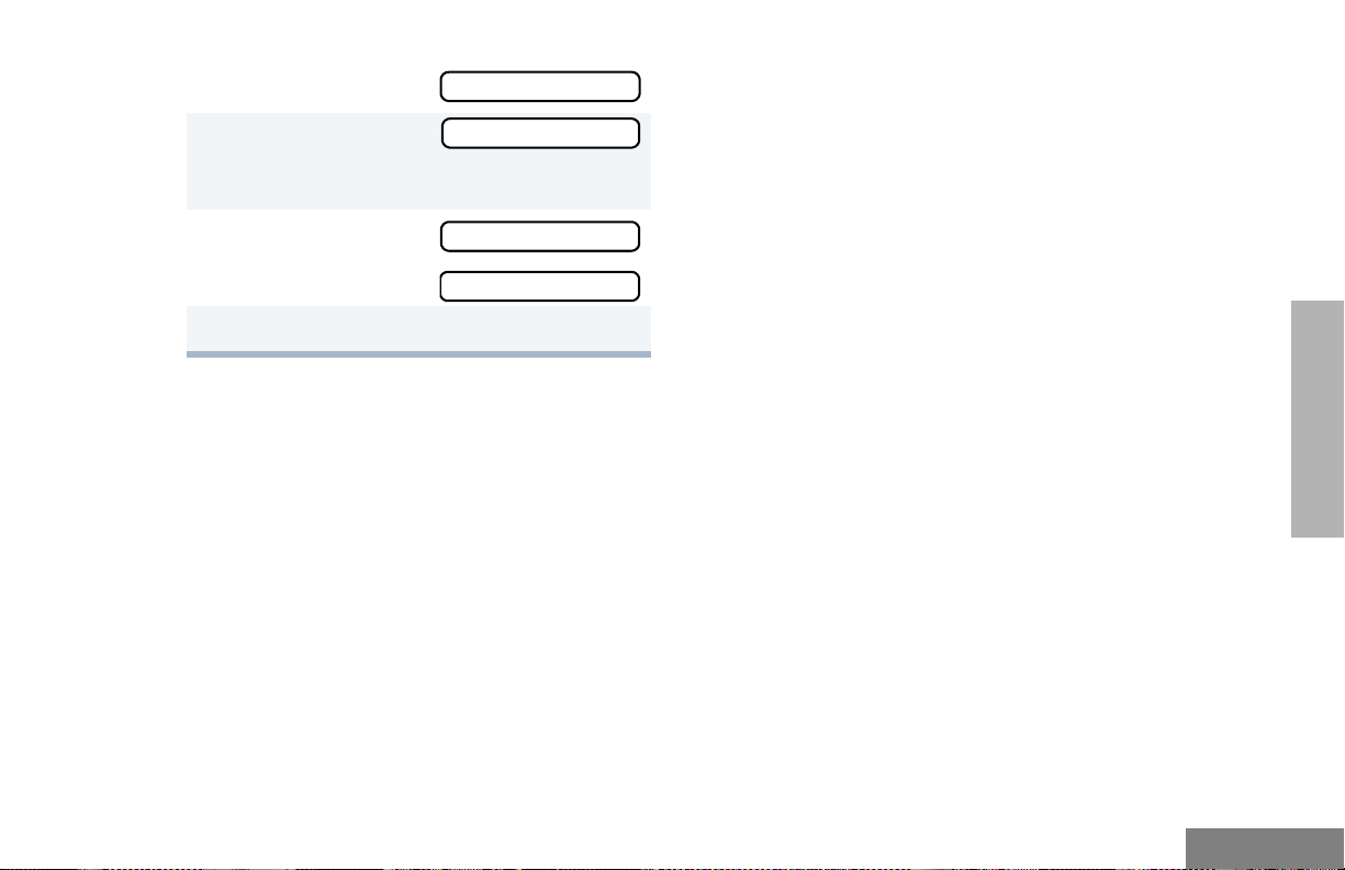
2 + or ? until
3 ) to select
You see the current scan status.
+ or ? until
4
–or–
5 ) to confirm your selection.
Pass Grp Scan
Pass Grp Scan
PpGp Scan Off?
PpGp Scan On?
AUTO GROUP SCAN G
(L TR TRUNKED OPERATION ONLY)
Auto Group Scan automatically scans
talkgroups within an LTR Trunked zone as
programmed by your dealer. Auto Group Scan
can be non-prioritized or prioritized:
• Non-prioritized Auto Group Scan
automatically scans all talkgroups
programmed with Auto Group Scan.
• Prioritized Auto Group Scan automatically
scans the selected talkgroup and all lower
four-numbered talkgroups. For example, if
Talkgroups 1, 3, and 4 have been
programmed by your dealer with Auto
Group Scan and Talkgroup 4 is selected,
your radio automatically scans talkgroups
1, 3, and 4, and skips Talkgroup 2.
To start Auto Group Scan:
Select a talkgroup that has been programmed
for Auto Group Scan by your dealer.
Note: You do not have to press a
preprogrammed Scan button.
• The display shows G when non-
prioritized Auto Group Scan has been
activated.
• The display shows H when prioritized
Auto Group Scan has been activated.
• The LED indicator does not light up during
Auto Group Scan.
To stop Auto Group Scan:
Select a talkgroup that has not been
programmed for Auto Group Scan by your
dealer.
ALL GROUP SCAN G
(LTR TRUNKED OPERATION ONLY)
With All Group Scan, your radio scans all
talkgroups within the selected LTR Trunked
zone.
When All Group Scan is enabled:
63
SCAN
English
Page 66

SCAN
• The display shows G.
• The LED indicator blinks green; it stops
blinking when your radio switches to an
active talkgroup.
Note: If you enter Menu mode while your radio
is scanning, scanning stops. The radio
resumes scanning when you exit Menu
mode.
To start All Group Scan, press the
preprogrammed All Group Scan button (see
page 16) once.
To stop All Group Scan, press the
preprogrammed All Group Scan button again.
–or–
To start or stop All Group Scan Operation
through the menu:
4 + or ? until
–or–
5 ) to confirm your selection.
All Group On?
All Group Off?
SYSTEM SCAN G
(LTR TRUNKED AND CONVENTIONAL
OPERATION ONLY)
System Scan scans Trunked talkgroups and
Conventional channels between LTR and
Conventional zones, as programmed by your
dealer. Up to 16 different talkgroups or
Conventional channels can be programmed
into each Scan list. You can edit these lists
through your radio’s menu (see page 66).
When System Scan is enabled:
English
1 ) to enter Menu mode.
2 + or ? until
3 ) to select
You see the current scan status.
64
All Group Scan
All Group Scan
• The display shows G.
• The LED indicator blinks green during
System Scan operation; it stops blinking
when your radio switches to an active
talkgroup or channel.
Page 67

Note: If you enter Menu mode while your radio
is scanning, scanning stops. The radio
resumes scanning when you exit Menu
mode.
To start or stop a System Scan:
Press the preprogrammed Scan button (see
page 22) to start or stop scanning,
–or–
Do the following:
1 ) to enter Menu mode.
Notes:
• In conventional zones only, if there is activity on a non-priority channel, the radio disconnects the user from the current
conversation and automatically switches to
an active priority channel. This is indicated
with a short alert tone.
• Your radio can either revert to a “selected”
channel or the “last active” channel
depending on its programming. For additional details, contact your local dealer.
SCAN
2 + or ? until
3 ) to select
You see the current scan status.
4 + or ? until
–or–
5 ) to confirm your selection.
System Scan
System Scan
Sys Scan On?
Sys Scan Off?
DELETING A NUISANCE CHANNEL
OR TALKGROUP
Note: This feature is available only with
PassPort Group Scan or System Scan
operation.
If a talkgroup or channel continually generates
unwanted calls (a “nuisance” channel), use the
preprogrammed Scan button to temporarily
delete the talkgroup or channel from the Scan
list.
65
English
Page 68

SCAN
To temporarily Delete a Nuisance Channel/
Talkgroup:
1 While your radio’s receiving activity is on the
nuisance channel, press and hold the Scan
button until you hear a high-pitched tone
(valid key press).
2 Release the Scan button. The nuisance
channel has been temporarily deleted from
your Scan list.
Note: In PassPort mode, you cannot delete
a priority channel/talkgroup (see
page 68), or the currently selected
talkgroup in a Scan list.
To restore a previously deleted Channel/
Talkgroup to the Scan List, restart the scan
operation or turn your radio off and on again.
Note: In PassPort mode, the talkgroup can
also be restored by scrolling through the
list, or switching the current selected
talkgroup or zone.
EDITING A SCAN LIST
Note: This feature is applicable to PassPort
Group Scan or System Scan operation
only.
One Scan list is assigned to each of the 16
positions on the Zone Selector knob. Each
Scan list can contain up to 16 talkgroups and/
or channels. The same talkgroup or channel
can be included in several Scan lists, and the
same Scan list can be assigned to several
Zone Selector positions.
When you edit a Scan list, you can either add,
delete, or prioritize talkgroups or channels.
Note: In PassPort mode, talkgroups cannot be
prioritized.
Your radio cannot receive any calls while you
are editing a Scan list. The display shows K
symbol while you are editing.
Note: In Conventional operation, even if there
is activity on a non-priority channel, your
radio automatically switches to an active
priority channel and indicates the activity
with a short tone.
English
66
Page 69

VIEW A SCAN LIST
To view Talkgroups or Channels in a Scan list:
1 ) to enter Menu mode.
+ or ? until
2
3 ) to select
4 + or ? until
Note: One Scan list per mode of operation
is available.
5 ) to select
6 + or ? until
7 ) to confirm your selection.
8 + or ? to see the talkgroup or channel
in your list.
Program Lists
Program Lists
Scan List
Scan List
View List
ADDING OR DELETING
TALKGROUPS OR CHANNELS
IN A SCAN LIST
To add or delete Talkgroups or Channels in a
Scan list:
1 ) to enter Menu mode.
+ or ? until
2
3 ) to select
4 + or ? until
Note: One Scan list per mode of operation
is available.
5 ) to select
6 + or ? until
or until
Program Lists
Program Lists
Scan List
Scan List
Add Entry?
Delete Entry?
SCAN
9 Hold down t to exit Menu mode.
7 ) to confirm your selection.
67
English
Page 70

SCAN
8 + or ? until you see the talkgroup or
channel you want to add or delete.
Note: You cannot delete the Primary
talkgroup from a Scan List in
PassPort mode.
9 ) to confirm your selection.
10 If you added a talkgroup or channel,
you see
–or–
If you delete a talkgroup or channel,
You see
Entry Saved
Delete?
PRIORITIZING A TALKGROUP OR
CHANNEL IN A SCAN LIST
Note: This feature is available with System
Scan operation only.
You can check the activity on one or two
talkgroups or channels more frequently than
others by prioritizing them.
Pri o r i t y Chann e l Scanning Sequence
None specified Ch1->Ch2->Ch3->
Ch4->…Ch1
Channel 2
(Priority 1)
Ch2->Ch1->Ch2->Ch3->
Ch2->Ch4->Ch2->…Ch1
English
) to confirm the deletion.
You see
11 ( to return to
–or–
Hold down t to exit Menu mode.
68
Entry Deleted
Add Entry?
Delete Entry?
Channel 2
(Priority 1) and
Channel 8
(Priority 2)
Ch2->Ch1->Ch8->Ch3->
Ch2->Ch4->Ch8->…Ch1
Note: In Conventional operation only, even if
there is activity on a non-priority channel,
your radio automatically switches to an
active priority channel and indicates the
activity with a short tone.
Page 71
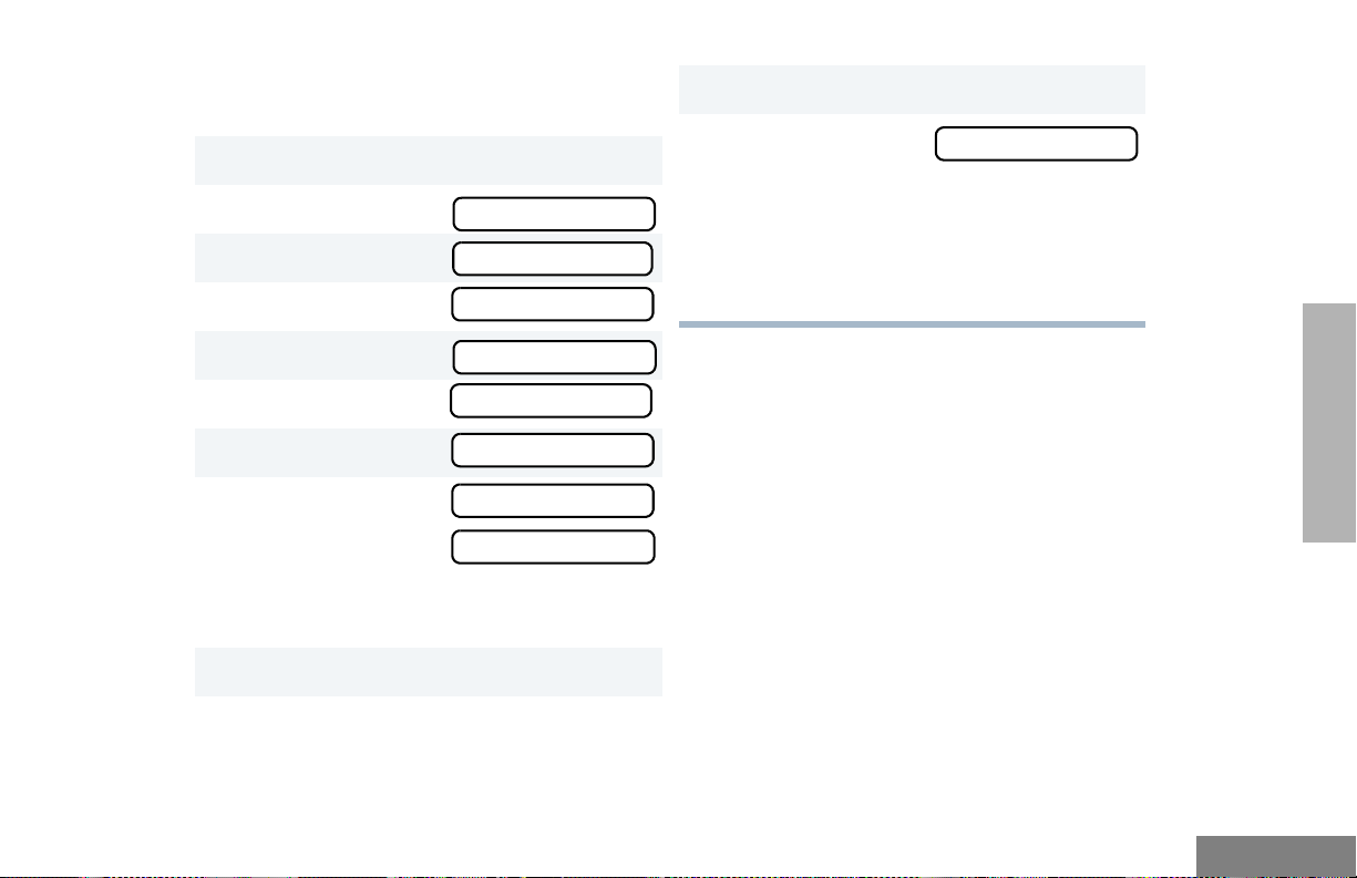
Setting Priority Talkgroups or Channe ls
To set a Priority Talkgroup or Channel:
1 ) to enter Menu mode.
+ or ? until
2
3 ) to select
4 + or ? until
Program Lists
Program Lists
Scan List
11 ) to prioritize that talkgroup or channel.
( to return to
12
–or–
Hold down ( to exit Menu mode.
Note: You cannot reprioritize a Priority 1
talkgroup or channel to Priority 2.
Edit Priority?
5 ) to select
6 + or ? until
7 ) to select
8 + or ? until
or until
You see the current priority talkgroup or
channel.
9 ) to select the desired priority level.
10 + or ? until you see the talkgroup or
channel you want to prioritize.
Scan List
Edit Priority?
Edit Priority?
Priority #1?
Priority #2?
SCAN
69
English
Page 72

SCAN
Notes
English
70
Page 73

PHONE
Your HT1250•LS+ radio allows you to place
and receive telephone calls through Tru nked
and Conventional systems (depending on
phone line availability). Telephone calls through
a repeater allow only one person to speak at a
time.
MAKING A PHONE CALL D
THROUGH A TRUNKED SYSTEM
Note: The following instructions assume your
radio has been programmed as follows
by your dealer using Customer
Programming Software (CPS).
2
) to enter Menu mode.
–or–
Press the preprogrammed Phone button, and
skip to step 5.
–or–
Press and release the Speed Dial button to
use the speed dial feature. Then press the
(1 to 9) key corresponding to the number you
want to call on the Phone list. Or press 0 if you
want to call the last number dialed. Press the
PTT button. A dial tone sounds. Press the PTT
button again to send the phone number.
–or–
For an LTR Trunked system, press and hold
the PTT button while dialing a number. (If your
radio has been programmed for Hot keypad,
this is a radio-wide setting).
• Dial type: Live
• Access/Deaccess type: Immediate Auto
• Tone Span: Timed - 100 ms tone duration
To initiate a Phone Call:
1 Select a Trunked zone and talkgroup that have
been programmed for telephone.
3 + or ? until
4 ) to confirm
The display shows
mode.
Phone
Phone
D when you are in Phone
71
PHONE
English
Page 74

5 Press and Release the PTT button.
• If phone access is successful, a dial tone
sounds.
• If phone access is unsuccessful, a
low-pitched alternating tone sounds.
Disconnect the call (see step 8) and try
again.
6 Enter the phone number with the keypad. The
number is automatically sent without pressing
the PTT button again.
–or–
+ or ? to
select a number from
the phone list.
Press and release the PTT button again to
7
send the number.
XXX-XXX-XXXX
MAKING A PHONE CALL D
THROUGH A CONVENTIONAL
SYSTEM
To initiate a Phone Call:
Press the preprogrammed Phone button, and
skip to step 5.
–or–
Press the PTT button, and if the Hot keypad
feature has been programmed by your dealer,
do the following:
1 Select a Conventional zone and channel that
have been programmed for telephone.
) to enter Menu mode.
2
3 + or ? until
Phone
PHONE
English
8 Hold your radio in a vertical position with the
microphone 1 to 2 inches (2.5 to 5
centimeters) away from your mouth. Press the
PTT button to talk; release it to listen.
9 Press and hold
and exit Phone mode.
The display no longer shows D.
72
( to disconnect the call
4 ) to select
The display shows D when you are in Phone
Mode.
Phone
Page 75

5 (For Conventional operation with auto access
only). You hear a series of tones, indicating
that an access code is being sent
automatically, and see your access code:
–or–
Enter your access code using the keypad.
6 When you hear a dial tone:
Enter the phone
number using the
keypad.
–or–
XXX-XXX-XXXX
Note: To redial the last number dialed (if not
using Speed Dial), press and release
the PTT button immediately after the
access code is sent. Your radio sends
the last number dialed.
–or–
If you entered your access code using
the keypad, press the ? key once
to access the last number dialed; then
press and release the PTT button.
8 Press and release the PTT button, if required
for your radio.
+ or ? to
select a number from
the phone list.
–or– (see step 7)
7 a Press and release the preprogrammed
Speed Dial button (see step 6) to use the
Speed Dial feature.
b Press the key (1 to 9) corresponding to the
number you want to call, or press 0 if you
want to call the last number dialed.
XXX-XXX-XXXX
9 Hold your radio in a vertical position with the
microphone 1 to 2 inches (2.5 to 5
centimeters) away from your mouth. Press the
PTT button to talk; release it to listen.
10 To disconnect a phone call, do one of the
following:
Enter the deaccess code using the keypad.
–or–
If your radio has the deaccess code
programmed, go to step 9.
PHONE
73
English
Page 76

11 To disconnect the call and exit Phone mode,
press and hold #. The display no longer
D.
shows
2 Press the PTT button to answer the phone
call. Press the PTT button to talk; release it to
listen.
PHONE
English
RECEIVING A PHONE CALL D
THROUGH A TRUNKED OR
CONVENTIONAL SYSTEM
To receive a Phone Call:
1 + or ? to select an LTR Trunked
talkgroup or Conventional channel that has
been programmed for telephone.
–or–
Activate any scan type containing a telephone
talkgroup or channel (see page 61).
Note: You do not have to select a PassPort
talkgroup or zone in PassPort mode.
When a phone call is received, a ringing tone
sounds, alerting you to answer the phone call.
Note: The display shows D when the radio is
in PassPort mode.
74
3 To disconnect the phone call and exit Phone
and Menu mode, press and hold
Note: The display no longer shows D in
PassPort mode.
#.
MODIFYING THE PHONE LIST K
Your radio contains a Phone list that holds up
to 25 phone numbers. The Phone list is shared
between Trunked and Conventional Ph one
operation. You can modify the Phone list in
three ways through your radio’s menu:
• Add an entry
• Delete an entry
• Edit an existing entry
The display shows K when you are modifying
the phone list.
To add an Entry to the Phone List:
1 ) to enter Menu mode.
Page 77

2 + or ? until
3 ) to select
4 + or ? until
5 ) to select
6 + or ? until
7 ) to select
You see
Program Lists
Program Lists
Phone List
Phone List
Add Entry?
Add Entry?
Enter Name
13 ) to store the phone number.
You see
14 ) to return to
15 Hold down ( to exit Menu mode.
Entry Saved
Add Entry?
To delete an Entry from the Phone List:
1 ) to enter Menu mode.
2 + or ? until
Program Lists
8 Enter the name using the keypad (see page 13).
9 ) to store the name.
You see
10 Enter the phone number using the keypad. You
can also add a dash (press >) and a Pause
Indicator (hold down # until the # character
on the display changes to a “P”).
11 ) to store the phone number.
12 + or ? until you see the location in the list
where you want to store the phone number .
Enter Phone #
3 ) to select
4 + or ? until
5 ) to select
6 + or ? until
7 ) to select
8 + or ? until you see the entry you
want to delete.
9 ) to select the entry.
Program Lists
Phone List
Phone List
Delete Entry?
Delete Entry
PHONE
75
English
Page 78

10 You see
Delete?
9 ) to select the entry.
PHONE
) again to confirm the deletion.
You see
11 ( to return to
–or–
Hold down ( to exit Menu mode.
Entry Deleted
Delete Entry?
To edit a Phone List Entry:
1 ) to enter Menu mode.
2 + or ? until
3 ) to select
4 + or ? until
5 ) to select
6 + or ? until
7 ) to select
+ or ? until you see the entry you
8
want to edit.
Program Lists
Program Lists
Phone List
Phone List
Edit Entry?
Edit Entry?
10 + or ? until
(to edit the name),
or until
(to edit the phone
number),
or until
(to edit the location in the phone list).
11 ) to confirm your selection.
Use the keypad to edit the entry (see page
12
14),
–or–
Edit Name?
Edit Number?
Edit Location?
+ or ? until you see the location
where you want to store the phone number.
13 ) to store the information.
14 ( to return to
–or–
Hold down
( to exit Menu mode.
Edit Entry?
English
76
Page 79

VOICE STORAGE
Voice Storage is standard in HT1250•LS+
radios. Please check with your dealer for
compatibility.
The Voice S tor age feature enables your radio to
perform seven types of voice related functions:
• Incoming Call Recording
• Voice Memo Recording
• Recorded Message Playback
• Recorded Message Delete
• Recorded Message Transmission
• Automatic Message Reply (“When
Available”)
• Message Time Stamping
There is a total of 120 seconds recording time
available for all voice storage activity. Your
dealer can divide the 120 seconds into a
defined number of equal length time slots. The
following table summarizes the slot length
options available with the HT1250•LS+ radio:
Number of Equal
Length Slots
1120
260
524
10 12
20 6
Slot Length
(Seconds)
When recording calls, keep in mind these time
slot guidelines:
• As a time slot becomes close to full, you
see a timer count down the final five
seconds.
When a time slot is completely full, an
alert tone sounds.
You see
Msg Slot Full
Recording stops.
• When all message slots have at least one
message stored, an alert tone sounds.
VOICE STORAGE
77
English
Page 80

VOICE STORAGE
If a voice storage record function is
requested, the display
shows:
Memory Full
INCOMING CALL RECORDING
The HT1250•LS+ radio allows you to record
incoming calls in either of two ways:
A confirmation tone sounds, indicating that
your radio has started recording.
Y our radio continues to record the call until the
message slot is full or until you release the
preprogrammed Record/Playback button.
2 Release the Record/Playback button to stop
recording.
English
• Selective Incoming Call Recording
• All Incoming Call Recording
Note: Your radio records the caller’s audio
transmissions only.
Selective Incoming Call Recording
This feature enables you to record incoming
calls selectively, or on a call-by-call basis.
To selectively record an Incoming Call:
1 Press and hold the preprogrammed Record/
Playback button (see page 16) while
receiving the call.
You see
78
Recording
All Incoming Call Recording
This feature enables you to automatically
record all incoming Trunked and Conventional
dispatch calls, Trunked and Conventional
telephone interconnect calls, and MDC
selective calls.
This feature is useful when you want to be
aware of channel activity while you are away
from your radio.
Note: This feature does not function in Scan
mode.
Page 81

To record all Incoming Calls:
1 ) to enter Menu mode.
+ or ? until
2
3 ) to select
4 + or ? until
5 ) to select
6 + or ? until
7 ) to select
8 The display
continuously flashes,
except when a call is
being recorded.
You see
while your radio is
recording.
Your radio also records the time stamp and
the channel alias in the message slot.
Voice Storage
Voice Storage
Record
Record
All Incoming
All Incoming
All Incoming
Recording
Press ( to stop recording.
9
–or–
Go to step 1 again to continue recording in the
next available slot.
Note: Five seconds before the message slot
ends,
you see:
(where XX =
remaining
seconds).
The “voice storage full” alert sounds
when the message slot is full, and
recording stops.
You see
Time Left XX
Msg Slot Full
VOICE MEMO RECORDING
In addition to recording calls received, your
HT1250•LS+ radio enables you to record voice
memos or personal reminders. This feat ur e is
useful when you want to quickly save phone
numbers, names, or any other brief voice
information. You can record voice memos
using the preprogrammed Record/Playback
button (see page 21) or your radio’s menu.
VOICE STORAGE
79
English
Page 82

Important Note:
To record properly, incoming calls cannot be
received while a voice memo is being
recorded.
To record a Voice Memo using the
Preprogrammed Record/Playback Button
:
To record a Voice Memo using the menu:
1 ) to enter Menu mode.
+ or ? until
2
3 ) to select
Voice Storage
Voice Storage
VOICE STORAGE
English
1 Press and hold the preprogrammed Record/
Playback button.
• You see
• A confirmation tone sounds, indicating that
your radio has started recording.
2 Speak clearly into the microphone to record
your memo. (Do not press the PTT button.)
Your radio records your memo until the
message slot is full, or until you release the
preprogrammed Record/Playback button.
3 Release the Record/Playback button to stop
recording.
80
Recording
4
+ or ? until
5 ) to select
6 + or ? until
7 ) to select
Y ou see:
8 Without pressing the PTT button, speak
clearly into the microphone to record your
memo. Y our radio records your memo until the
message slot is full or until you press
Note: To stop recording at any time,
press (.
9 Press ( to stop recording.
–or–
Repeat steps 7 and 8 to store additional
messages.
Record
Record
Voice Memo
Recording
(.
Page 83

RECORDED MESSAGE PLAYBACK
Your HT1250•LS+ radio allows you to list,
select, and Playback previously recorded
incoming call or voice memo messages. You
can play back a message using the
preprogrammed Record/Playback button ( see
page 2 1) or your radio’ s menu.
Note: Recorded message Playback cannot
be initiated while your radio is receiving.
In addition, your radio does not receive
any incoming calls while you play back
your messages.
Playing Msg XXX
2 To advan ce to the next message at any time
during Play back, press and release the
Record/Playback button again.
3 To exit/cancel Play Back mode, press and
release the preprogrammed Playback Exit
button (see page 21).
–or–
( to stop play back.
Press
To play back a Message using the Menu
1 ) to enter Menu mode.
:
VOICE STORAGE
To play back a Message using the
Preprogrammed Record/Playback Button:
1 Press and release the preprogrammed
Record/Playback button.
• The first
message plays,
and the display
shows (XXX =
the message
number)
Playing Msg XXX
2 + or ? until
3 ) to select
4 + or ? until
5 ) to select
6 + or ? until
Voice Storage
Voice Storage
Playback
Playback
001 12:00A 005
81
English
Page 84
7 ) to select
Message #
Time Stamp
001 12:00A 005
Duration (in seconds)
To delete a Message using the
Preprogrammed Delete Playback Button:
1 Press and release the preprogrammed
Record/Playback button (see page 21).
+ or ? to select the desired message.
2
VOICE STORAGE
English
8 + or ? to select the desired message.
9 Press ) to play the selected message.
10 + or ? anytime during playback to
advance to the next message.
RECORDED MESSAGE DELETE
Your HT1250•LS+ radio allows you to delete
previously recorded incoming call or voice
memo messages. You can delete a message
using either the preprogrammed Delete
Playback button (see page 21) or your radio’s
menu.
Note: You can delete messages only one at a
time.
82
3 Press and hold the preprogrammed Delete
Playback button to delete current message.
( to stop deleting messages.
4
To delete a Message using the Menu:
1 ) to enter Menu mode.
2 + or ? until
3 ) to select
4 + or ? until
5 ) to select
6 + or ? to select the desired message.
7 Press ) to delete the selected message.
Voice Storage
Voice Storage
Delete
Delete
Page 85

8 + or ? to select the another message
to be deleted, then go to step 7.
–or–
( to stop deleting messages.
Press
RECORDED MESSAGE
TRANSMISSION
This feature allows you to transmit a recorded
message to another radio user.
To transmit a Re cor d ed Mes sa ge:
1 Press and hold the PTT button to initiate the
message transmission.
AUTOMATIC MESSAGE REPLY:
“WHEN AVAILABLE”
(LTR TRUNKED AND CONVENTIONAL
OPERATION ONLY)
The Automatic Message Reply feature allows
you to transmit a recorded message to a caller
when your radio receives an MDC Selective
call.
To enable the Automatic Message Reply
feature
:
1 ) to enter Menu mode.
+ or ? until
2
Utilities
VOICE STORAGE
2 While holding down the PTT button, press the
preprogrammed Record/Playback button to
select and play back the desired recorded call
or memo.
3 When finished transmitting your message,
press the Record/Playback button again to
stop transmitting.
3 ) to select
4 + or ? until
5 ) to select
6 + or ? until
7 ) to select
Utilities
When Available
When Available
AutoReply On?
AutoReply On?
83
English
Page 86

To record a Message: To disable the Automatic Message Reply
1 + or ? until
feature
Recorded Msg
:
1 ) to enter Menu mode.
VOICE STORAGE
English
2 ) to select
Note: You see
3 Without pressing the PTT button, speak
clearly into the microphone to record your
memo. Your radio records your memo until
the message slot is full or until you press
(.
You see:
4 To exit or cancel recording, press (.
When Automatic Message Reply is enabled,
the recorded message is automatically
transmitted whenever your radio receives an
Individual call.
84
Recorded Msg
Recording
Msg Slot Full
2 + or ? until
3 ) to select
4 + or ? until
5 ) to select
6 + or ? until
7 ) to select
Utilities
Utilities
When Available
When Available
AutoReply Off?
AutoReply Off?
Page 87

AUDIO/TONE SETTINGS
You can customize the audio and tone feature
settings on your radio as follows:
1 ) to enter Menu mode.
2 + or ? until
3 ) to select
4 + or ? until you see the feature you
want to change (see the table on the following
page).
5 ) to select the feature. You see the
feature’s current setting.
6 + or ? to see a list of available
settings. (For Name and Call Tone Tagging,
see page 59.)
7 ) to select the desired setting.
Audio/Tones
Audio/Tones
85
SETTINGS
English
AUDIO/TONE
Page 88

Audio/Tone Settings
Feature What it Does Settings
SETTINGS
AUDIO/TONE
Alert Vol Lvl Makes the volume level of the audio and alert tones
independent. If turned on, it makes the alert tones follow
your radio’s default settings; if turned off, the alert tones
Ind Alert Off
Ind Alert On
are sounded at the setting determined by the position of
the volume knob.
Tone Disable Turns all alert and audio tones on or off. Tones On
Tones Off
Name and Call
Tone Tagging
Call Tone Tag
‡
Escalert
§
Companding Provides the same audio quality for 12.5 kHz and for
Keypad Tones Turns keypad tones on or off except for programmable
‡
LTR Trunked operation only. §Conventional operation only.
Assigns a specific ring tone when receiving a call from a
‡
§
specific user (see page 59).
‡
§
Assigns a specific tone when receiving a specific type of
radio call (see page 59).
Increases the volume of the alarm tones when a radio
call is not answered.
25 kHz channels.
buttons (see page 16).
Standard
Alert #1 – #7
Standard
Alert #1 – #7
Escalert On
Escalert Off
Compand On
Compand Off
Tones On
Tones Off
English
86
Page 89

UTILITIES
You can customize some of your radio’s
feature as follows:
1 ) to enter Menu mode.
2 + or ? until
3 ) to select
4 + or ? until you see the feature you
want to change (see table on the following
page).
5 ) to select the feature. You see the
feature’s current setting.
6 + or ? for available settings.
7 ) to select the desired setting.
Utilities
Utilities
UTILITIES
87
English
Page 90

Utilities Features
Feature What it Does Settings
UTILITIES
English
Squelch
§
Sets radio squelch to normal or tight (see page 90). Sqlch Tight
Sqlch Normal
Power Level Changes your radio’s power level to high, low, or auto
(see page 90).
Power High
Power Low
Power Auto
Clock Sets the time, or turns the clock on or off (see page 91). Clock On
Clock Off
Set Time
Reminder Alarm Sets the alarm, or turns it on or off (see page 91). Alarm On
Alarm Off
Set Time
Language
Selection
§‡
Selects the language to be shown on your radio’s display. English
Spanish
Portuguese
French
§
Conventional Operation only. ‡ LTR Trunked operati on only.
88
Page 91

Utilities Features
Feature What it Does Settings
Light Disable Turns your radio’s LED indicator, the display, and keypad
backlight on or off.
‡
§
When Available
Transmits a recorded message to a caller when your
radio receives an MDC Selective call.
Software Ver # In LTR Trunked and Conventional operation, displays
your radio’s software version number when you press
).
In PassPort operation, displays the PassPort software
version number when you press ).
Note: The LTR and Conventional software version
number may be different than the PassPort
software version number.
§
Conventional Operation only. ‡ LTR Trunked operation only.
Lights on
Lights off
Auto reply on
Auto reply off
Record msg
Review msg
——
UTILITIES
89
English
Page 92

UTILITIES
SETTING TIGHT OR NORMAL
SQUELCH
(CONVENTIONAL OPERATION ONLY)
Use this feature to filter out nuisance
(unwanted) calls and/or background noise.
However, tightening squelch could cause calls
from remote locations to be filtered out as well.
In this case, normal squelch may be more
desired.
To select Tight or Normal Squelch:
Press the preprogrammed Squelch button
(see page 20) to toggle between tight and
normal squelch,
–or–
Do the following:
1 ) to enter Menu mode.
2 + or ? until
3 ) to select
4 + or ? until
Utilities
Utilities
Squelch
5 ) to select
6 + or ? u nt il
–or–
until
7 ) to confirm the selection.
Squelch
Sqlch Tight?
Sqlch Normal?
SETTING THE POWER LEVEL B
Each channel in your radio has a predefined
transmit power level that can be changed.
• High powe r (S) allows you to reach a radio
that is farther away.
• Low power (R) conserves the battery’s
charge.
• Auto power (Conventional operation only)
automatically sets the optimal power level
based on the strength of the signal
received. If the received signal is weak, the
transmit level will be set to high, and vice
versa.
English
90
Page 93

Note: A message received from a nearby
radio might change your radio’s power
level to low. This may cause radios that
are farther away not to receive your
transmissions.
or until
or until
7 ) to confirm the selection.
Power Low?
Power Auto?
In PassPort mode, the power level is
predefined radio wide.
To set the Power Level:
Press the preprogrammed Power Level button
(see page 19) to toggle between low and high,
–or–
1 ) to enter Menu mode.
2 + or ? until
3 ) to select
4 + or ? until
5 ) to select
The display shows the current power level.
6 + or ? u nt i l
Utilities
Utilities
Power Level
Power Level
Power High?
SETTING THE CLOCK OR ALARM
To set the Clock/Alarm:
1 ) to enter Menu mode.
2 + or ? until
3 ) to select
4 + or ? until
or until
5 ) to confirm your selection.
6 + or ? until
7 ) to select
Utilities
Utilities
Clock
Reminder Alarm
Set Time?
Set Time?
UTILITIES
91
English
Page 94

8 When a setting is blinking, you can change it
with + or ?.
Hour (AM or PM)
Note: You cannot select “24 hr” for
3:05 PM
(AM/PM or 24 hr) Minutes
Reminder Alarm
9 < or > to move to the previous or next
setting.
) to save your changes.
10
UTILITIES
English
11 ( to return to
or
or
–or–
Hold down ( to exit Menu mode.
92
Utilities
Reminder Alarm
Clock
Page 95

WARRANTY
LIMITED WARRANTY
MOTOROLA COMMUNICATION
PRODUCTS
I. WHAT THIS WARRANTY COVERS AND
FOR HOW LONG:
MOTOROLA INC. (“MOTOROLA”)
warrants the MOTOROLA manufactured
Communication Products listed below
(“Product”) against defects in material and
workmanship under normal use and
service for a period of time from the date of
purchase as scheduled below:
HT1250•LS+ Portable
Units
Product Accessories One (1) Year
Motorola, at its option, will at no charge
either repair the Product (with new or
reconditioned parts), replace it (with a new
Two (2) Years
or reconditioned Product), or refund the
purchase price of the Product during the
warranty period provided it is returned in
accordance with the terms of this warranty .
Replaced parts or boards are warranted
for the balance of the original applicable
warranty period. All replaced parts of
Product shall become the property of
MOTOROLA.
This express limited warranty is extended
by MOTOROLA to the original end user
purchaser only and is not assignable or
transferable to any other party. This is the
complete warranty for the Product
manufactured by MOTOROLA.
MOTOROLA assumes no obligations or
liability for additions or modifications to this
warranty unless made in writing and
signed by an officer of MOTOROLA.
Unless made in a separate agreement
between MOTOROLA and the original end
user purchaser, MOTOROLA does not
warrant the installation, maintenance or
service of the Product.
WARRANTY
93
English
Page 96

WARRANTY
MOTOROLA cannot be responsible in any
way for any ancillary equipment not
furnished by MOTOROLA which is
attached to or used in connection with the
Product, or for operation of the Product
with any ancillary equipment, and all such
equipment is expressly excluded from this
warranty. Because each system which
may use the Product is unique,
MOTOROLA disclaims liability for range,
coverage, or operation of the system as a
whole under this warranty.
II. GENERAL PROVISIONS:
This warranty sets forth the full extent of
MOTOROLA'S responsibilities regarding
the Product. Repair , replacement or re fund
of the purchase price, at MOTOROLA’s
option, is the exclusive remedy. THIS
WARRANTY IS GIVEN IN LIEU OF ALL
OTHER EXPRESS WARRANTIES.
IMPLIED WARRANTIES, INCLUDING
WITHOUT LIMITATION, IMPLIED
WARRANTIES OF MERCHANTABILITY
AND FITNESS FOR A PARTICULAR
PURPOSE, ARE LIMITED TO THE
DURATION OF THIS LIMITED
WARRANTY. IN NO EVENT SHALL
MOTOROLA BE LIABLE FOR DAMAGES
IN EXCESS OF THE PURCHASE PRICE
OF THE PRODUCT, FOR ANY LOSS OF
USE, LOSS OF TIME, INCONVENIENCE,
COMMERCIAL LOSS, LOST PROFITS
OR SAVINGS OR OTHER INCIDENTAL,
SPECIAL OR CONSEQUENTIAL
DAMAGES ARISING OUT OF THE USE
OR INABILITY TO USE SUCH PRODUCT ,
TO THE FULL EXTENT SUCH MAY BE
DISCLAIMED BY LAW.
III. STATE LAW RIGHTS:
SOME STATES DO NOT ALLOW THE
EXCLUSION OR LIMITATION OF
INCIDENT AL OR CONSEQUENTIAL
DAMAGES OR LIMITATION ON HOW
LONG AN IMPLIED WARRANTY LASTS,
SO THE ABOVE LIMITATION OR
EXCLUSIONS MAY NOT APPLY.
This warranty gives specific legal rights,
and there may be other rights which may
vary from state to state.
English
94
Page 97

IV. HOW TO GET WARRANTY SERVICE:
You must provide proof of purchase
(bearing the date of purchase and Product
item serial number) in order to receive
warranty service and, also, deliver or send
the Product item, transportation and
insurance prepaid, to an authorized
warranty service location. Warranty
service will be provided by Motorola
through one of its authorized warranty
service locations. If you first contact the
company which sold you the Product (e.g.,
dealer or communication service provider),
it can facilitate your obtaining warranty
service. You can also call Motorola at
1-800-927-2744 US/Canada.
V. WHAT THIS WARRANTY DOES NOT
COVER:
A) Defects or damage resulting from use of the
Product in other than its normal and
customary manner.
B) Defects or damage from misuse, accident,
water, or neglect.
C) Defects or damage from improper testing,
operation, maintenance, installation,
alteration, modification, or adjustment.
D) Breakage or damage to antennas unless
caused directly by defects in material
workmanship.
E) A Product subjected to unauthorized
Product modifications, disassemblies or
repairs (including, without limitation, the
addition to the Product of non-Motorola
supplied equipment) which adversely affect
performance of the Product or interfere with
Motorola's normal warranty inspection and
testing of the Product to verify any warranty
claim.
F) Product which has had the serial number
removed or made illegible.
G) Rechargeabl e batteries if:
1) any of the seals on the battery
enclosure of cells are broken or show
evidence of tampering.
2) the damage or defect is caused by
charging or using the battery in
equipment or service other than the
Product for which it is specified.
H) Freight costs to the repair depot.
I) A Product which, due to illegal or
unauthorized alteration of the software/
firmware in the Product, does not function in
WARRANTY
95
English
Page 98

WARRANTY
accordance with MOTOROLA’ s published
specifications or the FCC type acceptance
labeling in effect for the Product at the time
the Product was initially distributed from
MOTOROLA.
J) Scratches or other cosmetic damage to
Product surfaces that does not affect the
operation of the Product.
K) Normal and customary wear and tear.
VI. PATENT AND SOFTWARE PROVISIONS:
MOTOROLA will defend, at its own expense, any
suit brought against the end user purchaser to
the extent that it is based on a claim that the
Product or parts infringe a United States patent,
and MOTOROLA will pay those costs and
damages finally awarded against the end user
purchaser in any such suit which are attributable
to any such claim, but such defense and
payments are conditioned on the following:
A) that MOTOROLA will be notified promptly in
writing by such purchaser of any notice of
such claim;
B) that MOTOROLA will have sole control of the
defense of such suit and all negotiations for
its settlement or compromise; and
C) should the Product or parts become, or in
MOTOROLA’s opinion be likely to become,
the subject of a claim of infringement of a
United States patent, that such purchaser
will permit MOTOROLA, at its option and
expense, either to procure for such
purchaser the right to continue using the
Product or parts or to replace or modify the
same so that it becomes non-infringing or to
grant such purchaser a credit for the Product
or parts as depreciated and accept its return.
The depreciation will be an equal amount
per year over the lifetime of the Product or
parts as established by MOTOROLA.
MOTOROLA will have no liability with respect to
any claim of patent infringement which is based
upon the combination of the Product or parts
furnished hereunder with software, apparatus or
devices not furnished by MOTOROLA, nor will
MOTOROLA have any liability for the use of
ancillary equipment or software not furnished by
MOTOROLA which is attached to or used in
connection with the Product. The foregoing
states the entire liability of MOTOROLA with
respect to infringement of patents by the Product
or any parts thereof.
Laws in the United States and other countries
preserve for MOTOROLA certain exclusive rights
for copyrighted MOTOROLA software such as
the exclusive rights to reproduce in copies and
English
96
Page 99

distribute copies of such Motorola software.
MOTOROLA software may be used in only the
Product in which the software was originally
embodied and such software in such Product
may not be replaced, copied, distributed,
modified in any way, or used to produce any
derivative thereof. No other use including,
without limitation, alteration, modification,
reproduction, distribution, or reverse engineering
of such MOTOROLA software or exercise of
rights in such MOTOROLA software is permitted.
No license is granted by implication, estoppel or
otherwise under MOTOROLA patent rights or
copyrights.
VII. GOVERNING LAW:
This Warranty is governed by the laws of the
State of Illinois, USA.
WARRANTY
97
English
Page 100

WARRANTY
Notes
English
98
 Loading...