

Page 1

CS4070 SCANNER
PRODUCT REFERENCE
GUIDE
Page 2

Page 3

CS4070 SCANNER
PRODUCT REFERENCE GUIDE
MN000762A01
Revision .6
June 2014
Page 4

ii CS4070 Scanner Product Reference Guide
© 2014 Motorola Solutions, Inc. All rights reserved.
No part of this publication may be reproduced or used in any form, or by any electrical or mechanical means,
without permission in writing from Motorola. This includes electronic or mechanical means, such as
photocopying, recording, or information storage and retrieval systems. The material in this manual is subject to
change without notice.
The software is provided strictly on an “as is” basis. All software, including firmware, furnished to the user is on
a licensed basis. Motorola grants to the user a non-transferable and non-exclusive license to use each
software or firmware program delivered hereunder (licensed program). Except as noted below, such license
may not be assigned, sublicensed, or otherwise transferred by the user without prior written consent of
Motorola. No right to copy a licensed program in whole or in part is granted, except as permitted under
copyright law. The user shall not modify, merge, or incorporate any form or portion of a licensed program with
other program material, create a derivative work from a licensed program, or use a licensed program in a
network without written permission from Motorola. The user agrees to maintain Motorola’s copyright notice on
the licensed programs delivered hereunder, and to include the same on any authorized copies it makes, in
whole or in part. The user agrees not to decompile, disassemble, decode, or reverse engineer any licensed
program delivered to the user or any portion thereof.
Motorola reserves the right to make changes to any software or product to improve reliability, function, or
design.
Motorola does not assume any product liability arising out of, or in connection with, the application or use of
any product, circuit, or application described herein.
No license is granted, either expressly or by implication, estoppel, or otherwise under any Motorola, Inc.,
intellectual property rights. An implied license only exists for equipment, circuits, and subsystems contained in
Motorola products.
MOTOROLA, MOTO, MOTOROLA SOLUTIONS and the Stylized M Logo are trademarks or registered
trademarks of Motorola Trademark Holdings, LLC and are used under license. All other trademarks are the
property of their respective owners.
Motorola Solutions, Inc.
One Motorola Plaza
Holtsville, New York 11742-1300
http://www.motorolasolutions.com
Warranty
For the complete Motorola hardware product warranty statement, go to:
http://www.motorolasolutions.com/warranty.
Page 5

Revision History
Changes to the original manual are listed below:
Change Date Description
-01 Rev .5 6/2014 See IPR list
-01 Rev .6 6/2014 Updated Master/Slave descriptions, added Win 7 pairing example
iii
Page 6

iv CS4070 Scanner Product Reference Guide
Page 7

TABLE OF CONTENTS
About This Guide
Introduction ..................................................................................................................................... xiii
Configurations................................................................................................................................. xiii
Accessories..................................................................................................................................... xiii
Chapter Descriptions ...................................................................................................................... xiv
Notational Conventions................................................................................................................... xv
Related Documents ........................................................................................................................ xv
Service Information......................................................................................................................... xvi
Chapter 1: Getting Started
Introduction .................................................................................................................................... 1-1
Unpacking the Scanner .................................................................................................................. 1-2
Inserting and Removing the Battery ............................................................................................... 1-2
Inserting the Battery ................................................................................................................. 1-2
Removing the Battery .............................................................................................................. 1-3
Charging Batteries ......................................................................................................................... 1-4
Charging the Battery in a CS4070 ........................................................................................... 1-4
Charging Spare Batteries ......................................................................................................... 1-4
Charging Temperature ............................................................................................................. 1-4
Connecting to the Host Computer .................................................................................................. 1-5
Batch Connection ..................................................................................................................... 1-5
Bluetooth Connection: Development Options .......................................................................... 1-5
Pairing ...................................................................................................................................... 1-5
Unpairing .................................................................................................................................. 1-6
Deleting the CS4070 from the Device List ............................................................................... 1-6
Configuring the Scanner ................................................................................................................ 1-7
Staging Multiple Scanners ....................................................................................................... 1-7
Editing the Configuration File ................................................................................................... 1-8
Page 8

vi CS4070 Scanner Product Reference Guide
Chapter 2: Scanning
Introduction .................................................................................................................................... 2-1
Scanning ........................................................................................................................................ 2-1
Deleting Bar Codes .................................................................................................................. 2-2
Transmitting Bar Code Data to Host .............................................................................................. 2-2
Transferring Data from a Batch Scanner ................................................................................. 2-2
Transferring Data from a Bluetooth Scanner ........................................................................... 2-2
User Interface Definitions .............................................................................................................. 2-3
LED Indications ........................................................................................................................ 2-3
Beeper Indications ................................................................................................................... 2-5
Chapter 3: User Preferences
Introduction .................................................................................................................................... 3-1
Scanning Sequence Examples ...................................................................................................... 3-1
Errors While Scanning ................................................................................................................... 3-1
User Preferences Default Parameters ........................................................................................... 3-2
Reset ............................................................................................................................................. 3-4
Reset Factory Defaults .................................................................................................................. 3-4
Set Date and Time ......................................................................................................................... 3-5
Set Date ................................................................................................................................... 3-5
Set Time ................................................................................................................................... 3-5
Cancel Date and Time Setting ................................................................................................. 3-5
Bluetooth Options .......................................................................................................................... 3-7
Master/Slave Set Up ................................................................................................................ 3-7
Bluetooth Unpair ...................................................................................................................... 3-8
Bluetooth HID Profile ............................................................................................................... 3-8
Bluetooth Serial Port Profile (SPP) .......................................................................................... 3-8
Clear Data ................................................................................................................................ 3-8
Bluetooth Security .................................................................................................................... 3-9
Set HID CoD to Zero ................................................................................................................ 3-10
User Preference Settings ............................................................................................................... 3-11
Parameter Bar Code Scanning ................................................................................................ 3-11
Beep After Good Decode ......................................................................................................... 3-11
Beeper Volume ........................................................................................................................ 3-12
Beeper Tone ............................................................................................................................ 3-13
Mute Beeper ............................................................................................................................ 3-13
Decode Pager Motor ................................................................................................................ 3-14
Decode Pager Motor Duration ................................................................................................. 3-14
Picklist Mode ............................................................................................................................ 3-16
Fuzzy 1D Processing ............................................................................................................... 3-16
Mirrored Image ......................................................................................................................... 3-17
Mobile Phone/Display Mode .................................................................................................... 3-17
PDF Prioritization ..................................................................................................................... 3-18
PDF Prioritization Timeout ....................................................................................................... 3-18
Data Options .................................................................................................................................. 3-19
Transmit Code ID Character .................................................................................................... 3-19
Prefix/Suffix Values .................................................................................................................. 3-20
Scan Data Transmission Format ............................................................................................. 3-21
Transmit “No Read” Message .................................................................................................. 3-22
Send Versions ............................................................................................................................... 3-23
Page 9

Table of Contents vii
Firmware Version ..................................................................................................................... 3-23
Scan Engine Version ............................................................................................................... 3-23
Dongle Version ........................................................................................................................ 3-23
Save Configuration ........................................................................................................................ 3-24
Chapter 4: Symbologies
Introduction .................................................................................................................................... 4-1
Scanning Sequence Examples ...................................................................................................... 4-1
Errors While Scanning ................................................................................................................... 4-2
Symbology Default Parameters ..................................................................................................... 4-2
Enable/Disable All Code Types ..................................................................................................... 4-7
UPC/EAN ....................................................................................................................................... 4-8
Enable/Disable UPC-A ............................................................................................................. 4-8
Enable/Disable UPC-E ............................................................................................................. 4-8
Enable/Disable UPC-E1 ........................................................................................................... 4-9
Enable/Disable EAN-8/JAN-8 .................................................................................................. 4-9
Enable/Disable EAN-13/JAN-13 .............................................................................................. 4-10
Enable/Disable Bookland EAN ................................................................................................ 4-10
Decode UPC/EAN/JAN Supplementals ................................................................................... 4-11
User-Programmable Supplementals ........................................................................................ 4-14
UPC/EAN/JAN Supplemental Redundancy ............................................................................. 4-14
UPC/EAN/JAN Supplemental AIM ID Format .......................................................................... 4-15
Transmit UPC-A Check Digit ................................................................................................... 4-16
Transmit UPC-E Check Digit ................................................................................................... 4-16
Transmit UPC-E1 Check Digit ................................................................................................. 4-17
UPC-A Preamble ..................................................................................................................... 4-18
UPC-E Preamble ..................................................................................................................... 4-19
UPC-E1 Preamble ................................................................................................................... 4-20
Convert UPC-E to UPC-A ........................................................................................................ 4-21
Convert UPC-E1 to UPC-A ...................................................................................................... 4-21
EAN-8/JAN-8 Extend ............................................................................................................... 4-22
Bookland ISBN Format ............................................................................................................ 4-22
UCC Coupon Extended Code .................................................................................................. 4-23
Coupon Report ......................................................................................................................... 4-24
ISSN EAN ................................................................................................................................ 4-24
Code 128 ....................................................................................................................................... 4-25
Enable/Disable Code 128 ........................................................................................................ 4-25
Set Lengths for Code 128 ........................................................................................................ 4-25
Enable/Disable GS1-128 (formerly UCC/EAN-128) ................................................................. 4-27
Enable/Disable ISBT 128 ......................................................................................................... 4-27
ISBT Concatenation ................................................................................................................. 4-28
Check ISBT Table .................................................................................................................... 4-29
ISBT Concatenation Redundancy ............................................................................................ 4-29
Code 128 Security Level .......................................................................................................... 4-30
Code 39 ......................................................................................................................................... 4-31
Enable/Disable Code 39 .......................................................................................................... 4-31
Enable/Disable Trioptic Code 39 ............................................................................................. 4-31
Convert Code 39 to Code 32 ................................................................................................... 4-32
Code 32 Prefix ......................................................................................................................... 4-32
Set Lengths for Code 39 .......................................................................................................... 4-33
Page 10

viii CS4070 Scanner Product Reference Guide
Code 39 Check Digit Verification ............................................................................................. 4-34
Transmit Code 39 Check Digit ................................................................................................. 4-34
Code 39 Full ASCII Conversion ............................................................................................... 4-35
Code 39 Security Level ............................................................................................................ 4-36
Code 93 ......................................................................................................................................... 4-37
Enable/Disable Code 93 .......................................................................................................... 4-37
Set Lengths for Code 93 .......................................................................................................... 4-37
Code 11 ......................................................................................................................................... 4-39
Code 11 ................................................................................................................................... 4-39
Set Lengths for Code 11 .......................................................................................................... 4-39
Code 11 Check Digit Verification ............................................................................................. 4-41
Transmit Code 11 Check Digits ............................................................................................... 4-42
Interleaved 2 of 5 (ITF) .................................................................................................................. 4-43
Enable/Disable Interleaved 2 of 5 ............................................................................................ 4-43
Set Lengths for Interleaved 2 of 5 ............................................................................................ 4-43
I 2 of 5 Check Digit Verification ................................................................................................ 4-45
Transmit I 2 of 5 Check Digit .................................................................................................... 4-46
Convert I 2 of 5 to EAN-13 ....................................................................................................... 4-46
I 2 of 5 Security Level .............................................................................................................. 4-47
Discrete 2 of 5 (DTF) ..................................................................................................................... 4-48
Enable/Disable Discrete 2 of 5 ................................................................................................. 4-48
Set Lengths for Discrete 2 of 5 ................................................................................................ 4-48
Codabar (NW - 7) .......................................................................................................................... 4-50
Enable/Disable Codabar .......................................................................................................... 4-50
Set Lengths for Codabar .......................................................................................................... 4-50
CLSI Editing ............................................................................................................................. 4-52
NOTIS Editing .......................................................................................................................... 4-52
Codabar Upper or Lower Case Start/Stop Characters Detection ............................................ 4-53
MSI ................................................................................................................................................ 4-54
Enable/Disable MSI ................................................................................................................. 4-54
Set Lengths for MSI ................................................................................................................. 4-54
MSI Check Digits ..................................................................................................................... 4-56
Transmit MSI Check Digit(s) .................................................................................................... 4-56
MSI Check Digit Algorithm ....................................................................................................... 4-57
Chinese 2 of 5 ................................................................................................................................ 4-58
Enable/Disable Chinese 2 of 5 ................................................................................................. 4-58
Matrix 2 of 5 ................................................................................................................................... 4-59
Enable/Disable Matrix 2 of 5 .................................................................................................... 4-59
Set Lengths for Matrix 2 of 5 .................................................................................................... 4-59
Matrix 2 of 5 Check Digit .......................................................................................................... 4-61
Transmit Matrix 2 of 5 Check Digit ........................................................................................... 4-61
Korean 3 of 5 ................................................................................................................................. 4-62
Enable/Disable Korean 3 of 5 .................................................................................................. 4-62
Inverse 1D ..................................................................................................................................... 4-63
GS1 DataBar ................................................................................................................................. 4-64
GS1 DataBar-14 ...................................................................................................................... 4-64
GS1 DataBar Limited ............................................................................................................... 4-64
GS1 DataBar Expanded .......................................................................................................... 4-65
Convert GS1 DataBar to UPC/EAN ......................................................................................... 4-65
GS1 DataBar Limited Security Level ....................................................................................... 4-66
Composite ...................................................................................................................................... 4-67
Page 11

Table of Contents ix
Composite CC-C ...................................................................................................................... 4-67
Composite CC-A/B ................................................................................................................... 4-67
Composite TLC-39 ................................................................................................................... 4-68
UPC Composite Mode ............................................................................................................. 4-68
GS1-128 Emulation Mode for UCC/EAN Composite Codes .................................................... 4-69
Postal Codes .................................................................................................................................. 4-70
US Postnet ............................................................................................................................... 4-70
US Planet ................................................................................................................................. 4-70
Transmit US Postal Check Digit ............................................................................................... 4-71
UK Postal ................................................................................................................................. 4-71
Transmit UK Postal Check Digit ............................................................................................... 4-72
Japan Postal ............................................................................................................................ 4-72
Australia Post ........................................................................................................................... 4-73
Australia Post Format .............................................................................................................. 4-74
Netherlands KIX Code ............................................................................................................ 4-75
USPS 4CB/One Code/Intelligent Mail ...................................................................................... 4-75
UPU FICS Postal ..................................................................................................................... 4-76
2D Symbologies ............................................................................................................................. 4-77
Enable/Disable PDF417 ........................................................................................................... 4-77
Enable/Disable MicroPDF417 .................................................................................................. 4-77
Code 128 Emulation ................................................................................................................ 4-78
Data Matrix ............................................................................................................................... 4-79
Data Matrix Inverse .................................................................................................................. 4-79
Decode Mirror Images (Data Matrix Only) ............................................................................... 4-80
Maxicode .................................................................................................................................. 4-81
QR Code .................................................................................................................................. 4-81
QR Inverse ............................................................................................................................... 4-82
MicroQR ................................................................................................................................... 4-82
Aztec ........................................................................................................................................ 4-83
Aztec Inverse ........................................................................................................................... 4-83
Han Xin .................................................................................................................................... 4-84
Han Xin Inverse ....................................................................................................................... 4-84
Symbology-Specific Security Levels .............................................................................................. 4-85
Redundancy Level ................................................................................................................... 4-85
Bi-directional Redundancy ....................................................................................................... 4-87
Security Level .......................................................................................................................... 4-88
Intercharacter Gap Size ........................................................................................................... 4-89
Macro PDF Features ...................................................................................................................... 4-90
Flush Macro Buffer ................................................................................................................... 4-90
Abort Macro PDF Entry ............................................................................................................ 4-90
Chapter 5: Advanced Data Formatting
Introduction .................................................................................................................................... 5-1
Chapter 6: Maintenance and Technical Specifications
Introduction .................................................................................................................................... 6-1
Maintenance .................................................................................................................................. 6-1
Troubleshooting ............................................................................................................................. 6-2
Technical Specifications ................................................................................................................ 6-3
Page 12

x CS4070 Scanner Product Reference Guide
Appendix A: Standard Default Parameters
Appendix B: Accessories
Overview ........................................................................................................................................ B-1
Accessories Summary ................................................................................................................... B-2
Single-Slot CS4070 Charging Cradle with Spare Battery Charger ................................................ B-3
Battery Charging Indications .................................................................................................... B-4
Bluetooth Connectivity ............................................................................................................. B-4
Eight-Slot CS4070 Charging Cradle .............................................................................................. B-5
Battery Charging Indications .................................................................................................... B-6
Bluetooth Connectivity ............................................................................................................. B-6
Eight-Slot Spare Battery Charger .................................................................................................. B-7
Battery Charging Indications .................................................................................................... B-8
LED Indications ........................................................................................................................ B-8
Wall Mount Brackets ...................................................................................................................... B-9
KT-102376-01R Bracket .......................................................................................................... B-9
KT-102375-01R Bracket .......................................................................................................... B-11
Bluetooth to USB HID Dongle ........................................................................................................ B-14
Pairing to a USB HID Device ................................................................................................... B-15
Lanyard with Clip ........................................................................................................................... B-16
Attaching and Removing the Lanyard ...................................................................................... B-16
Appendix C: Bluetooth Connection Examples
Overview ........................................................................................................................................ C-1
iPad Pairing Example .................................................................................................................... C-2
Android Pairing Example ............................................................................................................... C-3
Accessing the Nexus Phone Keyboard .................................................................................... C-4
Windows 7 Pairing Example .......................................................................................................... C-5
Windows 8 Pairing Example .......................................................................................................... C-7
PIN Entry Bar Codes ..................................................................................................................... C-9
Appendix D: Programming Reference
Code Type IDs ............................................................................................................................... D-1
Symbol Code Identifiers ................................................................................................................. D-4
AIM Code Identifiers ...................................................................................................................... D-6
GS1-128 (formerly UCC/EAN-128) ................................................................................................ D-11
Setting Prefixes and Suffixes ......................................................................................................... D-12
Appendix E: Sample Bar Codes
UPC-A ............................................................................................................................................ E-1
UPC-E ............................................................................................................................................ E-1
UPC-E1 .......................................................................................................................................... E-2
EAN-13 .......................................................................................................................................... E-2
EAN-8 ............................................................................................................................................ E-2
Code 39 ......................................................................................................................................... E-2
Trioptic Code 39 ............................................................................................................................ E-3
Code 93 ......................................................................................................................................... E-3
Page 13

Table of Contents xi
Code 11 ......................................................................................................................................... E-3
Codabar ......................................................................................................................................... E-4
MSI ................................................................................................................................................. E-4
Interleaved 2 of 5 ........................................................................................................................... E-4
Appendix F: Numeric Bar Codes
Numeric Bar Codes ........................................................................................................................ F-1
Cancel ............................................................................................................................................ F-3
Appendix G: ASCII Character Sets
Index
Page 14

xii CS4070 Scanner Product Reference Guide
Page 15

ABOUT THIS GUIDE
Introduction
The CS4070 Scanner Product Reference Guide provides general instructions for setting up, operating,
maintaining, and troubleshooting the scanner.
Configurations
The CS4070 scanner is available in the following configurations:
•
CS4070SR - Standard range, cordless Bluetooth
•
CS4070HC - Healthcare, cordless Bluetooth
Each scanner includes a micro USB host cable.
Accessories
See Table B-1 on page B-2 for a list of accessories.
Page 16

xiv CS4070 Scanner Product Reference Guide
Chapter Descriptions
Topics covered in this guide are as follows:
•
Chapter 1, Getting Started provides a product overview and describes how to charge, connect, and
configure the scanner.
•
Chapter 2, Scanning provides instructions for how to scan bar codes and send the data to a host, as well
as beeper and LED definitions.
•
Chapter 3, User Preferences describes each user preference feature and provides the programming bar
codes for selecting these features for the scanner. It also includes wireless communication parameters
and commonly used bar codes to customize how data is transmitted to the host device.
•
Chapter 4, Symbologies describes all symbology features and provides the programming bar codes for
selecting these features.
•
Chapter 5, Advanced Data Formatting briefly describes ADF, a means of customizing data before
transmission to the host device, and includes a reference to the ADF Programmer Guide.
•
Chapter 6, Maintenance and Technical Specifications provides information on how to care for the
scanner, troubleshooting, and technical specifications.
•
Appendix A, Standard Default Parameters provides a table of all host devices and miscellaneous
scanner defaults.
•
Appendix B, Accessories provides information on CS4070 accessories, which provide a variety of
product support capabilities.
•
Appendix C, Bluetooth Connection Examples provides pairing examples for several host devices.
•
Appendix D, Programming Reference provides a table of AIM code identifiers, ASCII character
conversions, and keyboard maps.
•
Appendix E, Sample Bar Codes includes sample bar codes.
•
Appendix F, Numeric Bar Codes includes numeric bar codes for parameters requiring specific numeric
values.
•
Appendix G, ASCII Character Sets includes character set tables.
Page 17

Notational Conventions
*Baud Rate 9600
Feature/Option
* Indicates Default
The following conventions are used in this document:
•
Italics are used to highlight the following:
• Chapters and sections in this and related documents
•
Bold text is used to highlight the following:
• Key names on a keypad
• Button names on a screen or window.
•
bullets (•) indicate:
• Action items
• Lists of alternatives
• Lists of required steps that are not necessarily sequential
•
Sequential lists (e.g., those that describe step-by-step procedures) appear as numbered lists.
•
Throughout the programming bar code menus, asterisks (*) are used to denote default parameter
settings.
About This Guide xv
NOTE This symbol indicates something of special interest or importance to the reader. Failure to read the note
will not result in physical harm to the reader, equipment or data.
CAUTION This symbol indicates that if this information is ignored, the possiblity of data or material damage may
WARNING! This symbol indicates that if this information is ignored the possibility that serious personal
Related Documents
•
CS4070 Scanner Quick Reference Guide (p/n MN000763A01) provides general information to help the
user get started with the scanner, including basic setup and operation instructions.
For the latest version of this guide and all guides, go to: http://www.motorolasolutions.com/support.
occur.
injury may occur.
Page 18

xvi CS4070 Scanner Product Reference Guide
Service Information
If you have a problem using the equipment, contact your facility's technical or systems support. If there is a
problem with the equipment, they will contact the Motorola Solutions Global Customer Support Center at:
http://www.motorolasolutions.com/support.
When contacting Motorola Solutions support, please have the following information available:
•
Serial number of the unit
•
Model number or product name
•
Software type and version number
Motorola responds to calls by e-mail, telephone or fax within the time limits set forth in service agreements.
If your problem cannot be solved by Motorola Solutions support, you may need to return your equipment for
servicing and will be given specific directions. Motorola is not responsible for any damages incurred during
shipment if the approved shipping container is not used. Shipping the units improperly can possibly void the
warranty.
If you purchased your business product from a Motorola business partner, please contact that business partner
for support.
Page 19

CHAPTER 1 GETTING STARTED
Scanner Window
Scan/Add Key
LED
Bluetooth Key / LED
Delete Key
Battery Level LEDs
Battery Level Key
Micro USB Port
Introduction
The CS4070 Scanner captures and stores bar codes for a variety of uses, and transmits bar code data to a
host via USB connection or Bluetooth.
Figure 1-1
This scanner supports the following host interfaces:
•
USB - The scanner connects to a USB host as a removable storage device, via a cradle or USB cable.
•
Bluetooth - The scanner supports Bluetooth HID connection to a host (the default) where the scanner
emulates a keyboard, as well as Serial Port Profile (SPP) connection where the scanner behaves as if
there is a serial connection.
CS4070 Scanner
Page 20

1 - 2 CS4070 Scanner Product Reference Guide
Battery
Release Latch
Unpacking the Scanner
Carefully remove all protective material from the scanner and save the shipping container for later storage and
shipping. Verify that you received the following equipment:
•
CS4070
•
Lithium-ion battery
•
Micro USB cable
•
Quick Start Guide.
Inspect the equipment. If any equipment is missing or damaged, contact Motorola Solutions support. See page
xvi for contact information.
Inserting and Removing the Battery
Inserting the Battery
Before using the scanner, insert the lithium-ion battery provided with the device.
1. Insert the battery, bottom first, into the battery compartment in the back of the device.
2. Press the battery down into the battery compartment until the battery release latch snaps into place.
Figure 1-2
Inserting the Battery
NOTE Position the battery correctly, with the battery charging contacts pointing towards the bottom of the
scanner.
Page 21

Removing the Battery
Release Latch
1. Lift the release latch to disengage the battery from the device.
Getting Started 1 - 3
Figure 1-3
2. Insert a finger nail into the top of the battery and lift to remove the battery.
Figure 1-4
Lift Release Latch
Push Battery Indent
Page 22

1 - 4 CS4070 Scanner Product Reference Guide
Charging Batteries
Before using the CS4070 for the first time, charge the battery using the micro USB cable or a cradle until the
green charge status LED lights. See Table 2-1 on page 2-3 for charge status indications. For information about
the charging accessories available for the device, see Appendix B, Accessories.
NOTE If the battery is removed or replaced, the device cold boots. The internal back up battery retains the
real-time clock.
Charging the Battery in a CS4070
Use one of the following methods to charge the battery when installed in a CS4070:
•
Connect the micro USB cable to the micro USB port on the device, and the other end to a USB port on a
host computer. Note that the scanner can not scan when connected to a host computer.
•
Connect the micro USB cable to the micro USB port on the device, and the other end to a USB power
adapter plugged into an AC outlet.
•
Insert the CS4070 into a powered single-slot or 8-slot charging cradle. See Single-Slot CS4070 Charging
Cradle with Spare Battery Charger on page B-3 or Eight-Slot CS4070 Charging Cradle on page B-5 for
more information.
The CS4070 begins charging. The charge status LED flashes amber while charging, then turns solid green
when fully charged. See Table 2-1 on page 2-3 for charging indications.
Charging Spare Batteries
To charge a spare battery, insert the battery into a slot of a powered spare battery charging accessory with the
charging contacts facing down, contacting the charging pins in the cradle. See Single-Slot CS4070 Charging
Cradle with Spare Battery Charger on page B-3 or Eight-Slot Spare Battery Charger on page B-7.
The battery begins charging. The charge LED on the cradle lights to show the charge status.
Charging Temperature
IMPORTANT:
Charge batteries in temperatures from 0°C to 35°C (32°F to 95°F).
Note that at temperatures above 30°C the charging temperature is monitored and controlled by the device and
the charging accessory. Charging is halted at temperatures above 35°C.
The device or accessory indicates when charging is disabled due to abnormal temperatures via its LED and/or
battery icon. See Table 2-1 on page 2-3, Table B-2 on page B-4, and Table B-3 on page B-8.
Page 23

Connecting to the Host Computer
Batch Connection
The micro USB cable enables communication between the CS4070 and a PC, and charges the battery in the
CS4070.
NOTE To enter batch scanning mode, the scanner cannot be paired to a Bluetooth host.
To connect the CS4070 to a USB device:
1. Connect the USB A end of the USB cable to a USB port of the host or device.
2. Connect the micro USB connector of the cable to the CS4070.
Getting Started 1 - 5
Figure 1-5
Micro USB Cable Communication
Bluetooth Connection: Development Options
Serial Port Profile
This Bluetooth profile emulates a serial cable to provide a simply implemented wireless replacement for
existing RS-232 based serial communications applications, including familiar control signals. It is the preferred
communication profile implementation because accidental key strokes from the keyboard or touch screen on
the host are not entered into the bar code data stream.
Human Interface Device Emulation
This Bluetooth profile is a lightweight wrapper of the Human Interface Device protocol defined for USB. Data
transmitted from the Bluetooth scanner appears as keyboard entries to the Bluetooth host (Smartphone, PC,
etc).
NOTE Wedge data appears within whichever application has input focus.
Pairing
Pairing the CS4070 with a host device typically requires holding the Bluetooth button to place the scanner in
discoverable mode, then scanning a pairing PIN. For pairing examples, see Appendix C, Bluetooth Connection
Examples.
Page 24
1 - 6 CS4070 Scanner Product Reference Guide
Supported Devices
The CS4070 supports connection to the following types of devices:
•
Apple (iPad Air, iPad mini, iTouch)
•
Android (Samsung Galaxy Tab 2, Panasonic Toughpad FZ-A1, ET1, TC55)
•
Windows 8 Pro (Motion C5te, Panasonic Toughpad FZ-G1, Lenovo ThinkPad Tablet 2
•
Windows 7 Pro (Panasonic Toughbook H2, Panasonic Toughbook CF-19)
•
Windows RT (Nokia Lumia 2520)
•
Windows Embedded Handheld 6.5.3 (Motorola MC67)
•
Windows Embedded Compact (CE7) (WT41N0)
Unpairing
To temporarily unpair the scanner and host, press the Bluetooth button. This disables Bluetooth and the
Bluetooth button stops blinking. Pressing the Bluetooth button again re-pairs the scanner with the host.
To permanently unpair the scanner and host, scan Unpair on page 3-8. This allows the scanner to pair to a
different host device.
NOTE To enter batch scanning mode, the scanner cannot be paired to a Bluetooth host (applies to CS4070
model only).
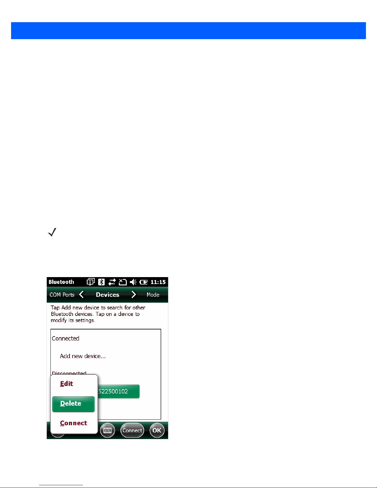
Deleting the CS4070 from the Device List
To delete the device from the discovered devices list, tap and old the device and select Delete.
Figure 1-6
Deleting Device
Page 25

Configuring the Scanner
To configure the scanner for initial use:
1. Scan the parameter bar codes in Chapter 3, User Preferences and Chapter 4, Symbologies to customize
scanner operation.
2. Scan the Save Configuration bar code on page 3-24 (also provided below).
NOTE When scanning parameter bar codes, scan each bar code within two minutes of the previous one. The
scanner enters sleep mode after two minutes of inactivity, and any parameter bar codes scanned and not
saved are ignored.
3. For additional customization, edit the Config.ini file on the scanner using the options in Editing the
Configuration File on page 1-8.
Getting Started 1 - 7
Save Configuration
4. CS4070 only: When deploying the new configuration to multiple scanners, to ensure unique CS4070 serial
numbers appear in the host’s discovery window, edit the
Config.ini file to either remove the BTName entry
or set it to blank (“BTName=”) to ensure that each scanner uses the default BT name of
CS4070:<serial number>.
Staging Multiple Scanners
After creating a config.ini file for one “golden” scanner with all desired settings, create a copy of the file from
this scanner and copy it to other scanners via USB connection. Set the time and date on the “cloned” scanners
by scanning bar codes from Set Date and Time on page 3-5.
NOTE CS4070 only: When deploying the new configuration to multiple scanners, to ensure unique CS4070
serial numbers appear in the host’s discovery window, edit the Config.ini file to either remove the
BTName entry or set it to blank (“BTName=”) to ensure that each scanner uses the default BT name of
CS4070:<serial number>.
NOTE Before deploying the Config.ini file to multiple scanners, make the file read only to prevent users from
overwriting the file when scanning Save Configuration or Reset Factory Defaults on page 3-4.
Page 26

1 - 8 CS4070 Scanner Product Reference Guide
Editing the Configuration File
Use a text editor such as Notepad to set configuration values in the Config.ini editable text file in the
\Parameters folder on the CS4070. Table 1-1 lists the programmable contents of the file.
NOTE If you make errors while editing the Config.ini file, the file LOG.TXT is created in the \Parameters folder.
Consult this log file to determine the errors and make corrections.
Table 1-1
Config.ini File Content
Parameter Values Description Default
BarcodeFile String In batch mode, the name of the batch file
BARCODES.TXT
containing bar codes scanned.
BarcodeDB String Bar code database filename. If the file
DBASE.TXT
exists scanned bar codes are checked
against its content. If the bar code exists
within the database, the scanner issues a
positive beep, if not a negative beep.
To engage this mode, create the
BarcodeDB.txt file on the CS4070. Note
that if this mode is engaged, no bar code
data is saved to the scanner.
BTPin String Default SPP PIN. 1234
BTName String Bluetooth device name (address) used
during discovery.
BTProfile HID
Selected BT profile. HID
CS4070:<serial
number>
SPP
BeepVolume Low
Beeper volume. High
Medium
High
BeepTone Low
Medium
High
Mute On
Off
WakeUpBeep Enable
Disable
Prefix Character Prefix character. <none>
Suffix Character Suffix character. 0x0D (CR)
Separator Character Separator character. ','
DateFormat MM/DD/YY
DD/MM/YY
MM/DD/YYYY
DD/MM/YYYY
Beeper tone/frequency. Medium
Mute the beeper. Off
Enable or disable the wake up beeper. Disable
Date format for batch data. Set to enable
date stamp
. See
Set Date on page 3-5
to
MM/DD/YY
(Enable)
set the date.
Enter no value to disable the date stamp,
for example: “
DateFormat =
“
Page 27

Getting Started 1 - 9
Table 1-1
Config.ini File Content (Continued)
Parameter Values Description Default
TimeFormat 12h
24h
Time format for batch data. Set to enable
time stamp
. See
Set Time on page 3-5
to
set the time.
Enter no value to disable the time stamp,
for example: “
TimeFormat =
“
ScanParam Variable Any scan engine parameter. Multiple
entries are allowed. Sent after reset or
when engine is powered.
For example:
ScanParam=0xf0,0x00,0x01
ScanParam=0xee,0x01
ScanParam=0x38,0x00
Sleep Integer Time in seconds before the scanner enters
sleep mode when no activity is detected.
BTSleep Integer Time in seconds before the scanner enters
sleep mode while paired to another
Bluetooth device when no activity is
detected.
ButtonPlus Enable
Enable or disable the Plus button. Enable
Disable
24h
(Enable)
<none>
0
0
ButtonMinus Enable
Disable
ButtonBT Enable
Disable
WakeUpLED Enable
Disable
LEDBlue Enable
Disable
LEDGreen Enable
Disable
LEDRed Enable
Disable
LEDAmber Enable
Disable
CodeID Enable
Disable
ScanLED Enable
Disable
Enable or disable the Minus button. Enable
Enable or disable the BT button. Enable
Enable or disable the wake-up LEDs. Enable
Enable or disable the blue LED for normal
Enable
operation and wake up.
Enable or disable the green LED for
Enable
normal operation and wake up.
Enable or disable the red LED for normal
Enable
operation and wake up.
Enable or disable the amber LED for
Enable
normal operation and wake up.
Enable or disable saving CodeID in the
scanned bar codes file. See
IDs on page D-1
.
Code Type
Enable or disable the LEDs that illuminate
Enable
Enable
while the scanner is active.
AutoReconnect Enable
Disable
Enable or disable automatic Bluetooth
reconnection to dongle or another device.
Disable
Page 28

1 - 10 CS4070 Scanner Product Reference Guide
Table 1-1
Config.ini File Content (Continued)
Parameter Values Description Default
LowBatteryIndication 0: no indication,
Specify behavior for low battery condition. 3
no operation
1: no indication,
allow operation
2: indication, no
operation
3: indication,
allow operation
DisableProtectToggle Enable (0)
Disable (1)
CAPLOCK On
Enable or disable the scan bar code
function.
Turn on or off the cap lock function. Off
Off
KeystrokeDelay Integer
(0 to 100)
For HID only: Set the delay, in
milliseconds, between emulated
keystrokes.
ZeroOutHIDClassOf
Device
Enable
Disable
Some versions of Broadcom stack
experience issues when connecting to HID
devices. Enable this feature if this is the
case.
Enable (0)
0 (ms)
Disable
Page 29

CHAPTER 2 SCANNING
Introduction
This chapter provides instructions for how to scan bar codes and send the data to a host. Beeper and LED
definitions are also included.
Scanning
See Chapter 1, Getting Started to install and program the scanner. To scan:
1. Aim the scanner at the bar code.
2. Press the scan (+) button.
Figure 2-1
3. Ensure the aiming dot is centered on the bar code.
The scanner beeps and the LED turns green to indicate a successful decode. See Table 2-1 and Table 2-2 for
beeper and LED definitions.
Scanning
NOTE The scanner cannot scan bar codes when it is connected to the host via the USB host cable.
Page 30

2 - 2 CS4070 Scanner Product Reference Guide
Deleting Bar Codes
In batch mode, to delete a bar code aim the scanner at the bar code and press the delete ( - ) button.
Figure 2-2
Deleting a Bar Code in Batch Mode
NOTE Bar codes cannot be deleted in Bluetooth mode.
Transmitting Bar Code Data to Host
Transferring Data from a Batch Scanner
The BarcodeFile.txt file within the \Scanned Barcodes directory on the scanner stores scanned bar code data.
Connect the scanner to the host via USB cable or the charging cradle and use Windows Explorer to navigate to
the scanner. Copy the bar code data file to the host.
To clear the bar code data, delete the BarcodeFile.txt file from the scanner, or scan the
page 3-8.
Autorun Feature
The scanner supports an autorun feature where you can build an autorun.inf file to automatically copy the data
to the host upon connection. Autorun.inf is a text-based configuration file that defines, upon connecting the
scanner, which executable or application to run on the host, which icon represents the scanner, and which
menu commands appear when you right-click the scanner icon from Windows Explorer. For more information,
search
autorun.inf on any search engine.
Clear Data bar code on
Transferring Data from a Bluetooth Scanner
When the scanner is paired to a host via Bluetooth, data transmits to the host after each scan and is not stored
on the device.
Out of Range Behavior
If the scanner moves out of range of the host, and does not re-pair with the host within the timeout period,
scanned data is lost and the scanner emits a 3-beep error tone.
When the radio loses connection, the Bluetooth LED stops its slow, consistent blinking and the beeper emits a
short high low beep. The Bluetooth LED blinks at a faster rate for a period of time while the device attempts to
reestablish pairing with the host, and when it returns within range the device repairs. If repairing is
unsuccessful the Bluetooth LED stops blinking.
Page 31

To manually reestablish paring when the device returns to range, press the Bluetooth LED button. Upon
Bluetooth pairing, the beeper emits a short low high beep and the Bluetooth LED starts its slow, consistent
blinking again.
User Interface Definitions
The scanner uses beeper and LED sequences to indicate various system events. Table 2-1 and Table 2-2
define these sequences and events.
LED Indications
Scanning 2 - 3
Table 2-1
Scan attempt Press scan (+)
Successful bar code scan Solid green Imager off
Battery charge status Press battery
Delete bar code
(when in batch mode)
Successful bar code deletion Solid amber Imager off
Unsuccessful deletion - item
doesn't exist (when in batch
mode)
LED Indications
Function Performed User Action LED Feedback Other
Flashing green Imager on
button
4 green Full charge (for 8 hours at 6
charge button
Press & hold
delete (-) button
3 green Less than 8 hours but more
2 green Less than 1 hour of operating
1 green ???
Flashing amber Imager on
Solid red Imager off
scans per minute)
than one of operating time
time
Clear all bar code data
(when delete (-) button enabled)
Successful clear all Solid amber Imager off
Charge scanner Connect scanner
Charge complete Solid green
Press & hold
delete (-) button 3
seconds past scan
time
to a host PC USB
port
Flashing amber Imager on
Flashing amber Scanner connects in mass
storage mode, auto-run
application on PC launches
Page 32

2 - 4 CS4070 Scanner Product Reference Guide
Table 2-1
LED Indications (Continued)
Function Performed User Action LED Feedback Other
Toggle data protection on or off
(when enabled)
Press & hold both
scan (+) and
None
delete (-) buttons
for 6 seconds
Successful data protection setting Solid amber
Enable Bluetooth radio Hold Bluetooth
button for 5
Rapidly flashing blue
LED
Bluetooth is enabled but has
not paired with a host
seconds
Bluetooth radio pairing Press Bluetooth
button
Bluetooth radio paired with host
and in range
Bluetooth radio out of range of
Slowly flashing blue
LED
Very slowly flashing
blue LED
Blue LED is off Stops transmitting beacons
host
Bluetooth radio returns to
communication range of host
Press any button Very slowly flashing
blue LED
Re-pairs device with host
Special Conditions
Memory low scan Press & hold scan
(+) button
Delete/Clear All Press & hold
Flashing red, then
normal operation
Normal operation
delete (-) button
Memory Full Scan Press & hold scan
Solid red
(+) button
Memory Full Delete/Clear All Press & hold
Normal operation
delete (-) button
Battery low indication - Scan Delete/Clear All
When enabled Normal operation Solid red, then
normal operation
When enabled and
performance disabled
When disabled and
Normal operation Solid red for 3
seconds
Normal operation Normal operation
performance enabled
When disabled and
Normal operation None No decode or upload
performance disabled
No decode or upload
Page 33

Scanning 2 - 5
Table 2-1
Data protection (enabled and on) Scan/function/ host
Unexpected failure Scan/function/dock Flashing red, green
Battery depleted Scan/function/dock None
LED Indications (Continued)
Function Performed User Action LED Feedback Other
Rapidly flashing red
com
and amber for 5
seconds
Beeper Indications
Table 2-2
Successful bar code scan Short high tone Imager off
Successful bar code deletion Short medium tone Imager off
Unsuccessful deletion - item doesn't
exist (when in batch mode)
Beeper Indications
Function Performed Beeper Feedback Other
Long short short Imager off
Contact support
Successful clear all 2 long medium tones Imager off
Successful data protection setting Short long short
Connect scanner to a host PC USB
port to charge scanner
Enable Bluetooth radio Short beep Hold Bluetooth button for 5 seconds
Bluetooth radio pairing Short low high
Bluetooth radio out of range of host Short high low Stops transmitting beacons
Bluetooth radio returns to
communication range of host
Attempt to scan when out of
Bluetooth radio range
Memory Full Scan Long tones for 5 seconds or
Low high
Short low high Re-pairs device with host
4 high tones No Bluetooth transmission
until scan button released
Page 34

2 - 6 CS4070 Scanner Product Reference Guide
Page 35

CHAPTER 3 USER PREFERENCES
*Medium Frequency
(1)
Feature/Option* Indicates Default
Option value
Introduction
This chapter describes each user preference feature and provides the programming bar codes for selecting
these features for the scanner.
The scanner ships with the settings shown in the User Preferences Default Table on page 3-2 (also see
Appendix A, Standard Default Parameters for all host device and miscellaneous scanner defaults). If the
default values suit the requirements, programming is not necessary. To change these values, scan a single bar
code or a short bar code sequence. After scanning Save Configuration on page 3-24, the new settings are
stored in non-volatile memory and are preserved when the scanner powers down.
To return all features to their default values, scan the Reset Factory Defaults bar code on page 3-4. Throughout
the programming bar code menus, default values are indicated with asterisks (
*).
Scanning Sequence Examples
In most cases, scan only one bar code to set a parameter value. For example, to set the beeper tone to high,
scan the High Frequency (beeper tone) bar code under Beeper Tone on page 3-13. The scanner issues a fast
warble beep and the LED turns green, indicating a successful parameter entry.
Other parameters, such as Data Transmission Formats, require scanning several bar codes. See the
parameter description for this procedure.
Errors While Scanning
Unless otherwise specified, if an error is made during a scanning sequence, re-scan the correct parameter.
Page 36

3 - 2 CS4070 Scanner Product Reference Guide
User Preferences Default Parameters
Table 3-1 lists the defaults for user preference parameters. To change any option, scan the appropriate bar
code(s) provided in this chapter.
NOTE See Appendix A, Standard Default Parameters for all default parameters.
Table 3-1
Reset N/A N/A
Reset Factory Defaults N/A N/A
Set Date N/A N/A
Set Time N/A N/A
Cancel Date and Time Settings N/A N/A
Bluetooth Options
Pairing Bar Code Format N/A N/A
Bluetooth Unpair N/A N/A
Bluetooth HID Profile N/A N/A
Bluetooth Serial Port Profile (SPP) N/A N/A
Clear Data N/A N/A
Authentication N/A Disable
Encryption N/A Disable
User Preferences Default Table
Parameter Parameter Number Factory Default
Page
Number
3-4
3-4
3-5
3-5
3-5
3-7
3-8
3-8
3-8
3-8
3-9
3-9
Set HID CoD to Zero N/A Disable
User Preferences
Beeper Volume 140 High
Beeper Tone 145 Medium Frequency
Mute Beeper N/A Do Not Mute
Decode Pager Motor 613 Disable
Decode Pager Motor Duration 626 150 msec
Picklist Mode 402 Disabled Always
Fuzzy 1D Processing 514 Enable
Mirrored Image 624 Disable
Mobile Phone/Display Mode 716 Disable
PDF Prioritization 719 Disable
3-10
3-12
3-13
3-13
3-14
3-14
3-16
3-16
3-17
3-17
3-18
Page 37

User Preferences 3 - 3
Table 3-1
User Preferences Default Table (Continued)
Parameter Parameter Number Factory Default
PDF Prioritization Timeout 720 200 ms
Data Options
Transmit Code ID Character 45 None
Prefix Value 99, 105 7013 <CR><LF>
Suffix 1 Value
Suffix 2 Value
98, 104
100, 106
7013 <CR><LF>
Transmit “No Read” Message 94 Disable
Scan Data Transmission Format 235 Data as is
Version Options
Send Firmware Version N/A N/A
Send Scan Engine Version N/A N/A
Send Dongle Version N/A N/A
Save Configuration
N/A N/A
Page
Number
3-18
3-19
3-20
3-20
3-22
3-21
3-23
3-23
3-23
3-24
Page 38

3 - 4 CS4070 Scanner Product Reference Guide
Reset
To reset the scanner and apply parameters from the configuration file, scan the following bar code.
Reset Factory Defaults
To reset the scanner to factory defaults, scan the following bar code. This rebuilds the configuration file from
program memory.
Reset
Reset Factory Defaults
Page 39

Set Date and Time
NOTE You must scan the configuration bar codes to set the time and date stamp on the scanner. The time and
date can not be set or edited in the config.ini file. This setting persists for three months if the scanner is
not used.
Set Date
User Preferences 3 - 5
Scan the Set Date bar code, then scan six numeric digits in the format mmddyy
Date and Time Settings on page 3-6
NOTE To change the date format from mmddyy, see DateFormat on page 1-8.
(first two for the month, second two for the day, third two for the year).
Set Date
from
Numeric Bar Codes for
Set Time
Scan the Set Time bar code, then scan four numeric digits in the format hhmm from Numeric Bar Codes for
Date and Time Settings on page 3-6 representing the time according to the 24 hour clock (first two for the hour,
second two for the minute).
For example, to set the time to 8:45 in the morning, scan the following bar code, then scan 0, 8, 4, 5. To set the
time to 3:07 in the afternoon, scan 1, 5, 0, 7.
NOTE To change the time format between 12h and 24h, see TimeFormat on page 1-9.
Cancel Date and Time Setting
Scan the Cancel Set Date/Time bar code to cancel the date and time settings.
Set Time
Cancel Set Date/Time
Page 40

3 - 6 CS4070 Scanner Product Reference Guide
Numeric Bar Codes for Date and Time Settings
0
2
1
3
4
5
6
7
8
9
Enter
Page 41

Bluetooth Options
Pairing Bar Code Content:
‘B’ + Bluetooth Address
B112233445566
Master/Slave Set Up
The scanner can be set up as a master or slave. When the scanner is set up as a slave, it is discoverable and
connectable to other devices. When the scanner is set up as a master, the Bluetooth address of the remote
device to which a connection is requested is required.
Slave
When the scanner is set up as a slave device, the scanner accepts an incoming connection request from a
remote device.
NOTE The number of scanners is dependent on the host’s capability.
Setting the scanner up as a slave typically requires holding the Bluetooth button to place the scanner in
discoverable mode, then scanning a pairing PIN. See Appendix C, Bluetooth Connection Examples for more
information.
User Preferences 3 - 7
Master
When the scanner is set up as a master, it initiates the radio connection to a slave device. Initiate the
connection in one of two ways:
•
Scan the bar code on the dongle. See Bluetooth to USB HID Dongle on page B-14.
•
Create and scan a pairing bar code with the remote device address. See Pairing Bar Code Format.
Pairing Bar Code Format
When connecting the scanner as a master to a remote Bluetooth device, you must create a pairing bar code for
the device. The Bluetooth address of the remote device must be known. Pairing bar codes are Code 128 bar
codes and are formatted as follows:
<Fnc 3>Bxxxxxxxxxxxx
where:
•
B (or LNKB) is the prefix
•
xxxxxxxxxxxx represents the 12-character Bluetooth address.
For example, if the remote device to which the scanner can connect has a Bluetooth address of
11:22:33:44:55:66, then the pairing bar code is:
Page 42

3 - 8 CS4070 Scanner Product Reference Guide
Bluetooth Unpair
Scan the following bar code to unpair the scanner from the host.
Bluetooth HID Profile
Scan Bluetooth HID Profile to cause the scanner to emulate a keyboard.
Unpair
Bluetooth HID Profile
Bluetooth Serial Port Profile (SPP)
Scan Bluetooth SPP to cause the scanner to emulate a serial connection.
Bluetooth SPP
Clear Data
Scan the following bar code to clear all batch bar code data on the scanner. This deletes the BarcodeFile.txt
from the scanner.
Clear Data
Page 43

User Preferences 3 - 9
Bluetooth Security
The scanner supports Bluetooth authentication and encryption. Either the remote device or the scanner
requests authentication, and then the scanner uses its programmed PIN to generate a link key. Once
authentication is complete, either device may then negotiate to enable encryption.
NOTE A remote device can still request authentication.
Authentication
To force authentication with a remote device (including the cradle), scan the Enable Authentication bar code
below. To prevent the scanner from forcing authentication, scan the Disable Authentication bar code below.
Enable Authentication
*Disable Authentication
Encryption
NOTE Authentication must be performed before encryption can take effect.
To set up the scanner for enabling encryption, scan Enable Encryption. To prevent the scanner from enabling
encryption, scan Disable Encryption. When enabled, the radio encrypts data
Enable Encryption
.
* Disable Encryption
Page 44

3 - 10 CS4070 Scanner Product Reference Guide
Set HID CoD to Zero
Some versions of Broadcom stack experience issues when connecting to HID devices. If experiencing issues,
delete the CS4070 device from the Broadcom stack, enable ZeroOutHIDClassOf Device on page 1-10 or scan
the Set HID CoD to Zero bar code below, and reconnect.
*Use HID CoD
Set HID CoD to Zero
Page 45

User Preference Settings
Parameter Bar Code Scanning
Parameter # 236
To disable the decoding of parameter bar codes, including the Set Defaults parameter bar codes, scan the
Disable Parameter Scanning bar code below. To enable decoding of parameter bar codes, scan Enable
Parameter Scanning.
*Enable Parameter Bar Code Scanning
(1)
User Preferences 3 - 11
Disable Parameter Bar Code Scanning
(0)
Beep After Good Decode
Parameter # 56
Scan a bar code below to select whether or not the scanner beeps after a good decode. If selecting Do Not
Beep After Good Decode, the beeper still operates during parameter menu scanning and to indicate error
conditions.
*Beep After Good Decode (Enable)
(1)
Do Not Beep After Good Decode (Disable)
(0)
Page 46

3 - 12 CS4070 Scanner Product Reference Guide
Beeper Volume
Parameter # 140
To select a decode beep volume, scan the appropriate bar code.
Low Volume
(2)
Medium Volume
(1)
*High Volume
(0)
Page 47
Beeper Tone
Parameter # 145
To select a decode beep frequency (tone), scan the appropriate bar code.
Low Frequency
(2)
User Preferences 3 - 13
*Medium Frequency
(1)
High Frequency
(0)
Mute Beeper
Scan the Mute Beeper bar code to mute the beeper.
Mute Beeper
(1)
*Do Not Mute Beeper
(0)
Page 48

3 - 14 CS4070 Scanner Product Reference Guide
Decode Pager Motor
Parameter # 613
The scanner includes a pager motor which, when enabled, vibrates the scanner for a period of time when a
successful decode occurs.
Scan a bar code below to enable or disable the pager motor. If enabled, scan the appropriate bar code to set
the period of time in which to vibrate the scanner (see Decode Pager Motor Duration below).
*Pager Motor Disable
(0)
Decode Pager Motor Duration
Parameter # 626
*150 msec
(15)
Pager Motor Enable
(1)
200 msec
(20)
Page 49

Decode Pager Motor Duration (continued)
250 msec
(25)
User Preferences 3 - 15
300 msec
(30)
400 msec
(40)
600 msec
(60)
500 msec
(50)
750 msec
(75)
Page 50

3 - 16 CS4070 Scanner Product Reference Guide
Picklist Mode
Parameter # 402
Picklist mode enables the scanner to decode only bar codes aligned under the center of the aiming pattern.
Select one of the following picklist modes:
•
Disabled Always - Picklist mode is always disabled.
•
Enabled Always - Picklist mode is always enabled.
NOTE With Picklist Mode enabled, the decode aiming pattern turns on even when the Decode Aiming Pattern on
page 7-15 is disabled.
*Disabled Always
(0)
Enabled Always
(2)
Fuzzy 1D Processing
Parameter # 514
This option is enabled by default to optimize decode performance on 1D bar codes, including damaged and
poor quality symbols. Disable this only if you experience time delays when decoding 2D bar codes, or in
detecting a no decode.
*Enable Fuzzy 1D Processing
(1)
Disable Fuzzy 1D Processing
(0)
Page 51

User Preferences 3 - 17
Mirrored Image
Parameter # 624
Enable this to scan images in reverse, or mirrored, as if seen through a mirror. This mode is useful in
applications requiring scanning through a mirror and using symbologies that do not decode in reverse.
Enabling this mode when using snapshot, video, or video viewfinder mode transmits images as mirrored
images.
*Disable Mirrored Image
(0)
Enable Mirrored Image
(1)
Mobile Phone/Display Mode
Parameter # 716
This mode improves bar code reading performance with target bar codes displayed on mobile phones and
electronic displays.
*Disable Mobile Phone/Display Mode
(0)
Enable Mobile Phone/Display Mode
(3)
Page 52

3 - 18 CS4070 Scanner Product Reference Guide
PDF Prioritization
Parameter # 719
Enable this feature to delay decoding a 1D bar code (Code 128 of 8 to 25 characters length) by the value
specified in PDF Prioritization Timeout. During that time the scanner attempts to decode a PDF417 symbol
(e.g., on a US driver's license), and if successful reports this only. If it does not decode (can not find) a PDF417
symbol, it reports the 1D symbol after the timeout. The 1D symbol must be in the device’s field of view for the
scanner to report it. This parameter does not affect decoding other symbologies.
*Disable PDF Prioritization
(0)
Enable PDF Prioritization
(1)
PDF Prioritization Timeout
Parameter # 720
When PDF Prioritization is enabled, this timeout specifies how long the scanner attempts to decode a PDF417
symbol before reporting the 1D bar code in the field of view.
Scan the following bar code, then scan four digits from Appendix F, Numeric Bar Codes that specify the timeout
in milliseconds. For example, to enter 400 ms, scan the following bar code, then scan 0400. The range is 0 to
5000 ms, and the default is 200 ms.
PDF Prioritization Timeout
Page 53

Data Options
Transmit Code ID Character
Parameter # 45
A Code ID character identifies the code type of a scanned bar code. This is useful when decoding more than
one code type. In addition to any single character prefix already selected, the Code ID character is inserted
between the prefix and the decoded symbol.
Select no Code ID character, a Symbol Code ID character, or an AIM Code ID character. For Code ID
Characters, see Appendix D, Programming Reference.
NOTE If you enable Symbol Code ID Character or AIM Code ID Character, and enable Transmit “No Read”
Message on page 3-22, the scanner appends the code ID for Code 39 to the NR message.
User Preferences 3 - 19
Symbol Code ID Character
(2)
*None
(0)
AIM Code ID Character
(1)
Page 54

3 - 20 CS4070 Scanner Product Reference Guide
Prefix/Suffix Values
Key Category Parameter # P = 99, S1 = 98, S2 = 100
Decimal Value Parameter # P = 105, S1 = 104, S2 = 106
You can append a prefix and/or one or two suffixes to scan data for use in data editing. To set a value for a
prefix or suffix, scan a four-digit number (i.e., four bar codes from Appendix F, Numeric Bar Codes) that
corresponds to that value. SeeAppendix G, ASCII Character Sets for the four-digit codes.
When using host commands to set the prefix or suffix, set the key category parameter to 1, then set the 3-digit
decimal value. See Appendix G, ASCII Character Sets for the four-digit codes.
To correct an error or change a selection, scan Cancel on page F-3.
NOTE To use Prefix/Suffix values, first set the Scan Data Transmission Format on page 3-21.
Scan Prefix
(7)
.
Scan Suffix 1
(6)
Scan Suffix 2
(8)
Data Format Cancel
Page 55

User Preferences 3 - 21
Scan Data Transmission Format
Parameter # 235
To change the scan data format, scan one of the following eight bar codes corresponding to the desired format.
NOTE If using this parameter do not use ADF rules to set the prefix/suffix.
To set values for the prefix and/or suffix, see Prefix/Suffix Values on page 3-20.
*Data As Is
(0)
<DATA> <SUFFIX 2>
(2)
<PREFIX> <DATA >
(4)
<DATA> <SUFFIX 1>
(1)
<DATA> <SUFFIX 1> <SUFFIX 2>
(3)
Page 56

3 - 22 CS4070 Scanner Product Reference Guide
Scan Data Transmission Format (continued)
<PREFIX> <DATA> <SUFFIX 2>
(6)
<PREFIX> <DATA> <SUFFIX 1>
(5)
<PREFIX> <DATA> <SUFFIX 1> <SUFFIX 2>
(7)
Transmit “No Read” Message
Parameter # 94
Scan a bar code below to select whether or not to transmit a No Read message. Enable this to transmit the
characters NR when a successful decode does not occur before trigger release or during the timeout period.
Disable this to send nothing to the host if a symbol does not decode.
NOTE If you enable Transmit No Read, and also enable Symbol Code ID Character or AIM Code ID Character
for Transmit Code ID Character on page 3-19, the scanner appends the code ID for Code 39 to the NR
message.
Enable No Read
(1)
*Disable No Read
(0)
Page 57

Send Versions
Firmware Version
Scan the following bar code to send the firmware version to the host.
Scan Engine Version
Scan the following bar code to send the scan engine version to the host.
User Preferences 3 - 23
Firmware Version
Scan Engine Version
Dongle Version
Scan the following bar code to send the dongle version to the host.
Dongle Version
Page 58

3 - 24 CS4070 Scanner Product Reference Guide
Save Configuration
Scan the following bar code after setting parameters to save the new configuration selections.
Save Configuration
Page 59

CHAPTER 4 SYMBOLOGIES
*Enable UPC-A
(1)
Feature/Option
* Indicates Default
Option Value
Introduction
This chapter describes symbology features and provides the programming bar codes for selecting these
features for the scanner. Before programming, follow the instructions in Chapter 1, Getting Started.
The scanner ships with the settings in Table 4-1 on page 4-2 (also see Appendix A, Standard Default
Parameters for all scanner defaults). If the default values suit requirements, programming is not necessary. Set
a feature value by scanning a single bar code or a short bar code sequences.
NOTE Most computer monitors allow scanning the bar codes directly on the screen. When scanning from the
screen, be sure to set the document magnification to a level where the bar code can be seen clearly, and
bars and/or spaces are not merging.
To return all features to default values, see Reset on page 3-4. Throughout the programming bar code menus,
asterisks (
*) indicate default values.
Scanning Sequence Examples
In most cases, scan only one bar code to set a parameter value. For example, to transmit bar code data
without the UPC-A check digit, scan the
Check Digit on page 4-16. The scanner issues a fast warble beep and the LED turns green, indicating a
successful parameter entry.
Other parameters, such as Set Length(s) for D 2 of 5 require scanning several bar codes in sequence. See
the parameter description for this procedure.
Do Not Transmit UPC-A Check Digit bar code under Transmit UPC-A
Page 60

4 - 2 CS4070 Scanner Product Reference Guide
Errors While Scanning
Unless otherwise specified, to correct an error during a scanning sequence, re-scan the correct parameter.
Symbology Default Parameters
Table 4-1 lists the defaults for all symbologies parameters. To change any option, scan the appropriate bar
code(s) in this chapter.
NOTE See Appendix A, Standard Default Parameters for all default parameters.
Table 4-1
Enable/Disable All Code Types
1D Symbologies
UPC/EAN
UPC-A 1 Enable 4-8
UPC-E 2 Enable 4-8
UPC-E1 12 Disable 4-9
EAN-8/JAN 8 4 Enable 4-9
EAN-13/JAN 13 3 Enable 4-10
Bookland EAN 83 Disable 4-10
Decode UPC/EAN/JAN Supplementals (2 and 5 digits) 16 Ignore 4-12
User-Programmable Supplementals
Symbology Parameter Defaults
Parameter
Supplemental 1:
Supplemental 2:
Parameter
Number
579
580
Default
4-7
000 4-14
Page
Number
UPC/EAN/JAN Supplemental Redundancy 80 10 4-14
Decode UPC/EAN/JAN Supplemental AIM ID 672 Combined 4-15
Transmit UPC-A Check Digit 40 Enable 4-16
Transmit UPC-E Check Digit 41 Enable 4-16
Transmit UPC-E1 Check Digit 42 Enable 4-17
UPC-A Preamble 34 System Character 4-18
UPC-E Preamble 35 System Character 4-18
UPC-E1 Preamble 36 System Character 4-20
Page 61

Symbologies 4 - 3
Table 4-1
Symbology Parameter Defaults (Continued)
Parameter
Parameter
Number
Default
Convert UPC-E to A 37 Disable 4-21
Convert UPC-E1 to A 38 Disable 4-21
EAN-8/JAN-8 Extend 39 Disable 4-22
Bookland ISBN Format 576 ISBN-10 4-22
UCC Coupon Extended Code 85 Disable 4-23
Coupon Report 730 New Coupon
4-24
Format
ISSN EAN 617 Disable 4-24
Code 128
Code 128 8 Enable 4-25
Set Length(s) for Code 128 209, 210 1 to 55 4-25
GS1-128 (formerly UCC/EAN-128) 14 Enable 4-27
ISBT 128 84 Enable 4-27
Page
Number
ISBT Concatenation 577 Autodiscriminate 4-28
Check ISBT Table 578 Enable 4-29
ISBT Concatenation Redundancy 223 10 4-29
Code 128 Security Level
751 Security Level 1
4-30
Code 39
Code 39 0 Enable 4-31
Trioptic Code 39 13 Disable 4-31
Convert Code 39 to Code 32 (Italian Pharmacy Code) 86 Disable 4-32
Code 32 Prefix 231 Disable 4-32
Set Length(s) for Code 39 18, 19 1 to 55 4-33
Code 39 Check Digit Verification 48 Disable 4-34
Transmit Code 39 Check Digit 43 Disable 4-34
Code 39 Full ASCII Conversion 17 Disable 4-35
Code 39 Security Level
750 Security Level 1
4-36
Code 93
Code 93 9 Disable 4-37
Set Length(s) for Code 93 26, 27 1 to 55 4-37
Page 62

4 - 4 CS4070 Scanner Product Reference Guide
Table 4-1
Symbology Parameter Defaults (Continued)
Parameter
Parameter
Number
Default
Code 11
Code 11 10 Disable 4-39
Set Lengths for Code 11 28, 29 4 to 55 4-39
Code 11 Check Digit Verification 52 Disable 4-41
Transmit Code 11 Check Digit(s) 47 Disable 4-42
Interleaved 2 of 5 (ITF)
Interleaved 2 of 5 (ITF) 6 Disable 4-43
Set Lengths for I 2 of 5 22, 23 6 to 55 4-43
I 2 of 5 Check Digit Verification 49 Disable 4-45
Transmit I 2 of 5 Check Digit 44 Disable 4-46
Convert I 2 of 5 to EAN 13 82 Disable 4-46
I 2 of 5 Security Level
1121 Security Level 1
4-47
Discrete 2 of 5 (DTF)
Page
Number
Discrete 2 of 5 5 Disable 4-48
Set Length(s) for D 2 of 5 20, 21 1 to 55 4-48
Codabar (NW - 7)
Codabar 7 Enable 4-50
Set Lengths for Codabar 24, 25 4 to 55 4-50
CLSI Editing 54 Disable 4-52
NOTIS Editing 55 Disable 4-52
Codabar Upper or Lower Case Start/Stop Characters
855 Upper Case
Detection
MSI
MSI 11 Disable 4-54
Set Length(s) for MSI 30, 31 4 to 55 4-54
MSI Check Digits 50 One 4-56
Transmit MSI Check Digit 46 Disable 4-56
MSI Check Digit Algorithm 51 Mod 10/Mod 10 4-57
Chinese 2 of 5
Chinese 2 of 5 408 Disable 4-58
Page 63

Symbologies 4 - 5
Table 4-1
Symbology Parameter Defaults (Continued)
Parameter
Parameter
Number
Default
Matrix 2 of 5
Matrix 2 of 5 618 Disable 4-59
Matrix 2 of 5 Lengths 619, 620 4 to 55 4-59
Matrix 2 of 5 Check Digit 622 Disable 4-61
Transmit Matrix 2 of 5 Check Digit 623 Disable 4-61
Korean 3 of 5
Korean 3 of 5 581 Disable
Inverse 1D
586 Regular 4-62
4-62
GS1 DataBar
GS1 DataBar-14 338 Enable 4-64
GS1 DataBar Limited 339 Disable 4-64
GS1 DataBar Expanded 340 Enable 4-65
Convert GS1 DataBar to UPC/EAN 397 Disable 4-65
Page
Number
GS1 DataBar Limited Security Level 728 Level 3 4-66
Composite
Composite CC-C 341 Disable 4-67
Composite CC-A/B 342 Disable 4-67
Composite TLC-39 371 Disable 4-68
UPC Composite Mode 344 Always Linked 4-68
GS1-128 Emulation Mode for UCC/EAN Composite Codes 427 Disable 4-69
Postal Codes
US Postnet 89 Disable 4-70
US Planet 90 Disable 4-70
Transmit US Postal Check Digit 95 Enable 4-71
UK Postal 91 Disable 4-71
Transmit UK Postal Check Digit 96 Enable 4-72
Japan Postal 290 Disable 4-72
Australia Post 291 Disable 4-73
Australia Post Format 718 Autodiscriminate 4-74
Netherlands KIX Code 326 Disable 4-75
Page 64

4 - 6 CS4070 Scanner Product Reference Guide
Table 4-1
Symbology Parameter Defaults (Continued)
Parameter
Parameter
Number
Default
USPS 4CB/One Code/Intelligent Mail 592 Disable 4-75
UPU FICS Postal 611 Disable 4-76
2D Symbologies
PDF417 15 Enable 4-77
MicroPDF417 227 Disable 4-77
Code 128 Emulation 123 Disable 4-78
Data Matrix 292 Enable 4-79
Data Matrix Inverse 588 Regular 4-79
Decode Mirror Images (Data Matrix Only) 537 Auto 4-80
Maxicode 294 Disable 4-81
QR Code 293 Enable 4-81
QR Inverse 587 Regular 4-82
MicroQR 573 Enable 4-82
Page
Number
Aztec 574 Enable 4-83
Aztec Inverse 589 Inverse Autodetect 4-83
Han Xin 1167 Disable 4-84
Han Xin Inverse 1168 Regular 4-84
Symbology-Specific Security Levels
Redundancy Level 78 1 4-85
Bi-directional Redundancy 67 Disable 4-87
Security Level 77 1 4-88
Intercharacter Gap Size 381 Normal 4-89
Macro PDF
Flush Macro PDF Buffer N/A N/A 4-90
Abort Macro PDF Entry N/A N/A 4-90
Page 65

Enable/Disable All Code Types
To disable all symbologies, scan Disable All Code Types below. This is useful when enabling only a few code
types.
Scan Enable All Code Types turn on (enable) all code types. This is useful when you want to read all codes,
or when you want to disable only a few code types.
Disable All Code Types
Symbologies 4 - 7
Enable All Code Types
Page 66

4 - 8 CS4070 Scanner Product Reference Guide
UPC/EAN
Enable/Disable UPC-A
Parameter # 1
To enable or disable UPC-A, scan the appropriate bar code below.
*Enable UPC-A
(1)
Enable/Disable UPC-E
Parameter # 2
To enable or disable UPC-E, scan the appropriate bar code below.
*Enable UPC-E
(1)
Disable UPC-A
(0)
Disable UPC-E
(0)
Page 67

Enable/Disable UPC-E1
Parameter # 12
UPC-E1 is disabled by default.
To enable or disable UPC-E1, scan the appropriate bar code below.
NOTE UPC-E1 is not a UCC (Uniform Code Council) approved symbology.
Enable UPC-E1
(1)
Symbologies 4 - 9
Enable/Disable EAN-8/JAN-8
Parameter # 4
To enable or disable EAN-8/JAN-8, scan the appropriate bar code below.
*Enable EAN-8/JAN-8
(1)
*Disable UPC-E1
(0)
Disable EAN-8/JAN-8
(0)
Page 68

4 - 10 CS4070 Scanner Product Reference Guide
Enable/Disable EAN-13/JAN-13
Parameter # 3
To enable or disable EAN-13/JAN-13, scan the appropriate bar code below.
*Enable EAN-13/JAN-13
(1)
Disable EAN-13/JAN-13
(0)
Enable/Disable Bookland EAN
Parameter # 83
To enable or disable Bookland EAN, scan the appropriate bar code below.
Enable Bookland EAN
(1)
NOTE If you enable Bookland EAN, select a Bookland ISBN Format on page 4-22. Also select either Decode
UPC/EAN Supplementals, Autodiscriminate UPC/EAN Supplementals, or Enable 978/979 Supplemental
Mode in Decode UPC/EAN/JAN Supplementals on page 4-11.
*Disable Bookland EAN
(0)
Page 69

Symbologies 4 - 11
Decode UPC/EAN/JAN Supplementals
Parameter # 16
Supplementals are bar codes appended according to specific format conventions (e.g., UPC A+2, UPC E+2,
EAN 13+2). The following options are available:
•
If you select Ignore UPC/EAN with Supplementals, and the scanner is presented with a UPC/EAN
plus supplemental symbol, the scanner decodes UPC/EAN and ignores the supplemental characters.
•
If you select Decode UPC/EAN with Supplementals, the scanner only decodes UPC/EAN symbols with
supplemental characters, and ignores symbols without supplementals.
•
If you select Autodiscriminate UPC/EAN Supplementals, the scanner decodes UPC/EAN symbols
with supplemental characters immediately. If the symbol does not have a supplemental, the scanner
must decode the bar code the number of times set via UPC/EAN/JAN Supplemental Redundancy on
page 4-14 before transmitting its data to confirm that there is no supplemental.
•
If you select one of the following Supplemental Mode options, the scanner immediately transmits
EAN-13 bar codes starting with that prefix that have supplemental characters. If the symbol does not
have a supplemental, the scanner must decode the bar code the number of times set via UPC/EAN/JAN
Supplemental Redundancy on page 4-14 before transmitting its data to confirm that there is no
supplemental. The scanner transmits UPC/EAN bar codes that do not have that prefix immediately.
• Enable 378/379 Supplemental Mode
• Enable 978/979 Supplemental Mode
NOTE If you select 978/979 Supplemental Mode and are scanning Bookland EAN bar codes, see
Enable/Disable Bookland EAN on page 4-10 to enable Bookland EAN, and select a format using
Bookland ISBN Format on page 4-22.
• Enable 977 Supplemental Mode
• Enable 414/419/434/439 Supplemental Mode
• Enable 491 Supplemental Mode
• Enable Smart Supplemental Mode - applies to EAN-13 bar codes starting with any prefix listed
previously.
• Supplemental User-Programmable Type 1 - applies to EAN-13 bar codes starting with a 3-digit
user-defined prefix. Set this 3-digit prefix using User-Programmable Supplementals on page 4-14.
• Supplemental User-Programmable Type 1 and 2 - applies to EAN-13 bar codes starting with either
of two 3-digit user-defined prefixes. Set the 3-digit prefixes using User-Programmable Supplementals
on page 4-14.
• Smart Supplemental Plus User-Programmable 1 - applies to EAN-13 bar codes starting with any
prefix listed previously or the user-defined prefix set using User-Programmable Supplementals on
page 4-14.
• Smart Supplemental Plus User-Programmable 1 and 2 - applies to EAN-13 bar codes starting with
any prefix listed previously or one of the two user-defined prefixes set using User-Programmable
Supplementals on page 4-14.
NOTE To minimize the risk of invalid data transmission, select either to decode or ignore supplemental
characters.
Page 70

4 - 12 CS4070 Scanner Product Reference Guide
Decode UPC/EAN/JAN Supplementals (continued)
Decode UPC/EAN/JAN Only With Supplementals
(1)
*Ignore Supplementals
(0)
Autodiscriminate UPC/EAN/JAN Supplementals
(2)
Enable 978/979 Supplemental Mode
(5)
Enable 378/379 Supplemental Mode
(4)
Enable 977 Supplemental Mode
(7)
Page 71

Decode UPC/EAN/JAN Supplementals (continued)
Enable 414/419/434/439 Supplemental Mode
(6)
Symbologies 4 - 13
Enable 491 Supplemental Mode
(8)
Enable Smart Supplemental Mode
(3)
Supplemental User-Programmable Type 1 and 2
(10)
Supplemental User-Programmable Type 1
(9)
Smart Supplemental Plus User-Programmable 1
(11)
Smart Supplemental Plus User-Programmable 1 and 2
(12)
Page 72

4 - 14 CS4070 Scanner Product Reference Guide
User-Programmable Supplementals
Supplemental 1: Parameter # 579
Supplemental 2: Parameter # 580
If you selected a Supplemental User-Programmable option from Decode UPC/EAN/JAN Supplementals on
page 4-11, select User-Programmable Supplemental 1 to set the 3-digit prefix. Then select the 3 digits using
the numeric bar codes beginning on page F-1. Select User-Programmable Supplemental 2 to set a second
3-digit prefix. Then select the 3 digits using the numeric bar codes beginning on page F-1. The default is 000
(zeroes).
User-Programmable Supplemental 1
User-Programmable Supplemental 2
UPC/EAN/JAN Supplemental Redundancy
Parameter # 80
If you selected Autodiscriminate UPC/EAN/JAN Supplementals, this option adjusts the number of times to
decode a symbol without supplementals before transmission. The range is from two to thirty times. Five or
above is recommended when decoding a mix of UPC/EAN/JAN symbols with and without supplementals. The
default is 10.
Scan the bar code below to set a decode redundancy value. Next, scan two numeric bar codes in Appendix F,
Numeric Bar Codes. Enter a leading zero for single digit numbers. To correct an error or change a selection,
scan Cancel on page F-3.
UPC/EAN/JAN Supplemental Redundancy
Page 73

Symbologies 4 - 15
UPC/EAN/JAN Supplemental AIM ID Format
Parameter # 672
Select an output format when reporting UPC/EAN/JAN bar codes with Supplementals with Transmit Code ID
Character on page 3-19 set to
•
Separate - transmit UPC/EAN with supplementals with separate AIM IDs but one transmission, i.e.:
]E<0 or 4><data>]E<1 or 2>[supplemental data]
•
Combined – transmit UPC/EAN with supplementals with one AIM ID and one transmission, i.e.:
]E3<data+supplemental data>
•
Separate Transmissions - transmit UPC/EAN with supplementals with separate AIM IDs and separate
transmissions, i.e.:
]E<0 or 4><data>
]E<1 or 2>[supplemental data]
AIM Code ID Character:
Separate
(0)
Separate Transmissions
(2)
*Combined
(1)
Page 74

4 - 16 CS4070 Scanner Product Reference Guide
Transmit UPC-A Check Digit
Parameter # 40
The check digit is the last character of the symbol used to verify the integrity of the data. Scan the appropriate
bar code below to transmit the bar code data with or without the UPC-A check digit. It is always verified to
guarantee the integrity of the data.
*Transmit UPC-A Check Digit
(1)
Do Not Transmit UPC-A Check Digit
(0)
Transmit UPC-E Check Digit
Parameter # 41
The check digit is the last character of the symbol used to verify the integrity of the data. Scan the appropriate
bar code below to transmit the bar code data with or without the UPC-E check digit. It is always verified to
guarantee the integrity of the data.
*Transmit UPC-E Check Digit
(1)
Do Not Transmit UPC-E Check Digit
(0)
Page 75

Symbologies 4 - 17
Transmit UPC-E1 Check Digit
Parameter # 42
The check digit is the last character of the symbol used to verify the integrity of the data. Scan the appropriate
bar code below to transmit the bar code data with or without the UPC-E1 check digit. It is always verified to
guarantee the integrity of the data.
*Transmit UPC-E1 Check Digit
(1)
Do Not Transmit UPC-E1 Check Digit
(0)
Page 76

4 - 18 CS4070 Scanner Product Reference Guide
UPC-A Preamble
Parameter # 34
Preamble characters are part of the UPC symbol, and include Country Code and System Character. There are
three options for transmitting a UPC-A preamble to the host device: transmit System Character only, transmit
System Character and Country Code (“0” for USA), and transmit no preamble. Select the appropriate option to
match the host system.
No Preamble (<DATA>)
(0)
System Character & Country Code
(< COUNTRY CODE> <SYSTEM CHARACTER>
<DATA>)
(2)
*System Character (<SYSTEM CHARACTER>
<DATA>)
(1)
Page 77

Symbologies 4 - 19
UPC-E Preamble
Parameter # 35
Preamble characters are part of the UPC symbol, and include Country Code and System Character. There are
three options for transmitting a UPC-E preamble to the host device: transmit System Character only, transmit
System Character and Country Code (“0” for USA), and transmit no preamble. Select the appropriate option to
match the host system.
No Preamble (<DATA>)
(0)
System Character & Country Code
(< COUNTRY CODE> <SYSTEM CHARACTER>
<DATA>)
(2)
*System Character (<SYSTEM CHARACTER>
<DATA>)
(1)
Page 78

4 - 20 CS4070 Scanner Product Reference Guide
UPC-E1 Preamble
Parameter # 36
Preamble characters are part of the UPC symbol, and include Country Code and System Character. There are
three options for transmitting a UPC-E1 preamble to the host device: transmit System Character only, transmit
System Character and Country Code (“0” for USA), and transmit no preamble. Select the appropriate option to
match the host system.
No Preamble (<DATA>)
(0)
System Character & Country Code
(< COUNTRY CODE> <SYSTEM CHARACTER> <DATA>)
(2)
*System Character (<SYSTEM CHARACTER> <DATA>)
(1)
Page 79

Symbologies 4 - 21
Convert UPC-E to UPC-A
Parameter # 37
Enable this to convert UPC-E (zero suppressed) decoded data to UPC-A format before transmission. After
conversion, the data follows UPC-A format and is affected by UPC-A programming selections (e.g., Preamble,
Check Digit).
Disable this to transmit UPC-E decoded data as UPC-E data, without conversion.
Convert UPC-E to UPC-A (Enable)
(1)
*Do Not Convert UPC-E to UPC-A (Disable)
(0)
Convert UPC-E1 to UPC-A
Parameter # 38
Enable this to convert UPC-E1 decoded data to UPC-A format before transmission. After conversion, the data
follows UPC-A format and is affected by UPC-A programming selections (e.g., Preamble, Check Digit).
Disable this to transmit UPC-E1 decoded data as UPC-E1 data, without conversion.
Convert UPC-E1 to UPC-A (Enable)
(1)
*Do Not Convert UPC-E1 to UPC-A (Disable)
(0)
Page 80
4 - 22 CS4070 Scanner Product Reference Guide
EAN-8/JAN-8 Extend
Parameter # 39
Enable this parameter to add five leading zeros to decoded EAN-8 symbols to make them compatible in format
to EAN-13 symbols. Disable this to transmit EAN-8 symbols as is.
Enable EAN/JAN Zero Extend
(1)
*Disable EAN/JAN Zero Extend
(0)
Bookland ISBN Format
Parameter # 576
If you enabled Bookland EAN using Enable/Disable Bookland EAN on page 4-10, select one of the following
formats for Bookland data:
•
Bookland ISBN-10 - The scanner reports Bookland data starting with 978 in traditional 10-digit format
with the special Bookland check digit for backward-compatibility. Data starting with 979 is not considered
Bookland in this mode.
•
Bookland ISBN-13 - The scanner reports Bookland data (starting with either 978 or 979) as EAN-13 in
13-digit format to meet the 2007 ISBN-13 protocol.
*Bookland ISBN-10
(0)
NOTE For Bookland EAN to function properly, first enable Bookland EAN using Enable/Disable Bookland EAN
on page 4-10, then select either Decode UPC/EAN Supplementals, Autodiscriminate UPC/EAN
Supplementals, or Enable 978/979 Supplemental Mode in Decode UPC/EAN/JAN Supplementals on
page 4-11.
Bookland ISBN-13
(1)
Page 81

Symbologies 4 - 23
UCC Coupon Extended Code
Parameter # 85
Enable this parameter to decode UPC-A bar codes starting with digit ‘5’, EAN-13 bar codes starting with digit
‘99’, and UPC-A/GS1-128 Coupon Codes. UPCA, EAN-13, and GS1-128 must be enabled to scan all
types of Coupon Codes.
Enable UCC Coupon Extended Code
(1)
*Disable UCC Coupon Extended Code
(0)
NOTE See UPC/EAN/JAN Supplemental Redundancy on page 4-14 to control autodiscrimination of the GS1-128
(right half) of a coupon code.
Page 82

4 - 24 CS4070 Scanner Product Reference Guide
Coupon Report
Parameter # 730
Select an option to determine which type of coupon format to support.
•
Select Old Coupon Format to support UPC-A/GS1-128 and EAN-13/GS1-128.
•
Select New Coupon Format as an interim format to support UPC-A/GS1-DataBar and
EAN-13/GS1-DataBar.
•
If you select Autodiscriminate Format, the scanner supports both Old Coupon Format and New
Coupon Format.
Old Coupon Format
(0)
Autodiscriminate Coupon Format
(2)
ISSN EAN
Parameter # 617
To enable or disable ISSN EAN, scan the appropriate bar code below.
Enable ISSN EAN
(1)
*New Coupon Format
(1)
*Disable ISSN EAN
(0)
Page 83
Code 128
Enable/Disable Code 128
Parameter # 8
To enable or disable Code 128, scan the appropriate bar code below.
*Enable Code 128
Symbologies 4 - 25
(1)
Disable Code 128
(0)
Set Lengths for Code 128
Parameter # 209, 210
The length of a code refers to the number of characters (i.e., human readable characters), including check
digit(s) the code contains. Set lengths for Code 128 to any length, one or two discrete lengths, or lengths within
a specific range. The default is 1 to 55.
NOTE When setting lengths for different bar code types, enter a leading zero for single digit numbers.
•
One Discrete Length - Select this option to decode only Code 128 symbols containing a selected
length. Select the length using the numeric bar codes in Appendix F, Numeric Bar Codes. For example,
to decode only Code 128 symbols with 14 characters, scan Code 128 - One Discrete Length, then scan
1 followed by 4. To correct an error or change the selection, scan Cancel on page F-3.
•
Two Discrete Lengths - Select this option to decode only Code 128 symbols containing either of
two selected lengths. Select lengths using the numeric bar codes in Appendix F, Numeric Bar Codes.
For example, to decode only Code 128 symbols containing either 2 or 14 characters, select Code 128 -
Two Discrete Lengths, then scan 0, 2, 1, and then 4. To correct an error or change the selection,
scan Cancel on page F-3.
•
Length Within Range - Select this option to decode a Code 128 symbol with a specific length
range. Select lengths using numeric bar codes in Appendix F, Numeric Bar Codes. For example, to
decode Code 128 symbols containing between 4 and 12 characters, first scan Code 128 - Length
Within Range. Then scan 0, 4, 1, and 2 (enter a leading zero for single digit numbers). To correct an
error or change the selection, scan Cancel on page F-3.
•
Any Length - Select this option to decode Code 128 symbols containing any number of characters
within the scanner’s capability.
Page 84

4 - 26 CS4070 Scanner Product Reference Guide
Set Lengths for Code 128 (continued)
Code 128 - One Discrete Length
Code 128 - Two Discrete Lengths
Code 128 - Length Within Range
Code 128 - Any Length
Page 85

Enable/Disable GS1-128 (formerly UCC/EAN-128)
Parameter # 14
To enable or disable GS1-128, scan the appropriate bar code below.
*Enable GS1-128
(1)
Symbologies 4 - 27
Disable GS1-128
(0)
Enable/Disable ISBT 128
Parameter # 84
ISBT 128 is a variant of Code 128 used in the blood bank industry. Scan a bar code below to enable or disable
ISBT 128. If necessary, the host must perform concatenation of the ISBT data.
*Enable ISBT 128
(1)
Disable ISBT 128
(0)
Page 86

4 - 28 CS4070 Scanner Product Reference Guide
ISBT Concatenation
Parameter # 577
Select an option for concatenating pairs of ISBT code types:
•
If you select Disable ISBT Concatenation, the scanner does not concatenate pairs of ISBT codes
it encounters.
•
If you select Enable ISBT Concatenation, there must be two ISBT codes in order for the scanner to
decode and perform concatenation. The scanner does not decode single ISBT symbols.
•
If you select Autodiscriminate ISBT Concatenation, the scanner decodes and concatenates pairs of
ISBT codes immediately. If only a single ISBT symbol is present, the scanner must decode the symbol
the number of times set via ISBT Concatenation Redundancy on page 4-29 before transmitting its data to
confirm that there is no additional ISBT symbol.
Disable ISBT Concatenation
(0)
*Autodiscriminate ISBT Concatenation
(2)
Enable ISBT Concatenation
(1)
Page 87

Symbologies 4 - 29
Check ISBT Table
Parameter # 578
The ISBT specification includes a table that lists several types of ISBT bar codes that are commonly used in
pairs. If you set ISBT Concatenation to Enable, enable Check ISBT Table to concatenate only those pairs
found in this table. Other types of ISBT codes are not concatenated.
*Enable Check ISBT Table
(1)
Disable Check ISBT Table
(0)
ISBT Concatenation Redundancy
Parameter # 223
If you set ISBT Concatenation to Autodiscriminate, use this parameter to set the number of times the
scanner must decode an ISBT symbol before determining that there is no additional symbol.
Scan the bar code below, then scan two numeric bar codes in Appendix F, Numeric Bar Codes to set a value
between 2 and 20. Enter a leading zero for single digit numbers. To correct an error or change a selection,
scan Cancel on page F-3. The default is 10.
ISBT Concatenation Redundancy
Page 88

4 - 30 CS4070 Scanner Product Reference Guide
Code 128 Security Level
Parameter # 751
Code 128 bar codes are vulnerable to misdecodes, particularly when Code 128 Lengths is set to Any Length.
The scanner offers four levels of decode security for Code 128 bar codes. There is an inverse relationship
between security and scanner aggressiveness. Increasing the level of security can reduce scanning
aggressiveness, so select only the level of security necessary.
•
Code 128 Security Level 0: This setting allows the scanner to operate in its most aggressive state,
while providing sufficient security in decoding most in-spec bar codes.
•
Code 128 Security Level 1: A bar code must be successfully read twice, and satisfy certain safety
requirements before being decoded. This default setting eliminates most misdecodes.
•
Code 128 Security Level 2: Select this option with greater bar code security requirements if Security
Level 1 fails to eliminate misdecodes.
•
Code 128Security Level 3: If you selected Security Level 2, and misdecodes still occur, select this
security level to apply the highest safety requirements. A bar code must be successfully read three times
before being decoded.
NOTE Selecting this option is an extreme measure against mis-decoding severely out-of-spec bar codes.
Selecting this level of security significantly impairs the decoding ability of the scanner. If this level of
security is required, try to improve the quality of the bar codes.
Code 128Security Level 0
(0)
Code 128 Security Level 2
(2)
*Code 128 Security Level 1
(1)
Code 128 Security Level 3
(3)
Page 89
Code 39
Enable/Disable Code 39
Parameter # 0
To enable or disable Code 39, scan the appropriate bar code below.
*Enable Code 39
Symbologies 4 - 31
(1)
Disable Code 39
(0)
Enable/Disable Trioptic Code 39
Parameter # 13
Trioptic Code 39 is a variant of Code 39 used in the marking of computer tape cartridges. Trioptic Code 39
symbols always contain six characters. To enable or disable Trioptic Code 39, scan the appropriate bar code
below.
Enable Trioptic Code 39
(1)
*Disable Trioptic Code 39
(0)
NOTE You cannot enable Trioptic Code 39 and Code 39 Full ASCII simultaneously.
Page 90

4 - 32 CS4070 Scanner Product Reference Guide
Convert Code 39 to Code 32
Parameter # 86
Code 32 is a variant of Code 39 used by the Italian pharmaceutical industry. Scan the appropriate bar code
below to enable or disable converting Code 39 to Code 32.
NOTE Code 39 must be enabled for this parameter to function.
Enable Convert Code 39 to Code 32
(1)
*Disable Convert Code 39 to Code 32
(0)
Code 32 Prefix
Parameter # 231
Scan the appropriate bar code below to enable or disable adding the prefix character “A” to all Code 32 bar
codes.
NOTE Convert Code 39 to Code 32 must be enabled for this parameter to function.
Enable Code 32 Prefix
(1)
*Disable Code 32 Prefix
(0)
Page 91

Symbologies 4 - 33
Set Lengths for Code 39
Parameter # 18, 19
The length of a code refers to the number of characters (i.e., human readable characters), including check
digit(s) the code contains. Set lengths for Code 39 to any length, one or two discrete lengths, or lengths within
a specific range. If Code 39 Full ASCII is enabled, Length Within a Range or Any Length are the preferred
options. The default is 1 to 55.
NOTE When setting lengths for different bar code types, enter a leading zero for single digit numbers.
•
One Discrete Length - Select this option to decode only Code 39 symbols containing a selected length.
Select the length using the numeric bar codes in Appendix F, Numeric Bar Codes. For example, to
decode only Code 39 symbols with 14 characters, scan Code 39 - One Discrete Length, then scan 1
followed by 4. To correct an error or change the selection, scan Cancel on page F-3.
•
Two Discrete Lengths - Select this option to decode only Code 39 symbols containing either of two
selected lengths. Select lengths using the numeric bar codes in Appendix F, Numeric Bar Codes. For
example, to decode only Code 39 symbols containing either 2 or 14 characters, select Code 39 - Two
Discrete Lengths, then scan 0, 2, 1, and then 4. To correct an error or change the selection, scan
Cancel on page F-3.
•
Length Within Range - Select this option to decode a Code 39 symbol with a specific length
range. Select lengths using numeric bar codes in Appendix F, Numeric Bar Codes. For example, to
decode Code 39 symbols containing between 4 and 12 characters, first scan Code 39 - Length
Within Range. Then scan 0, 4, 1, and 2 (enter a leading zero for single digit numbers). To correct an
error or change the selection, scan Cancel on page F-3.
•
Any Length - Select this option to decode Code 39 symbols containing any number of characters within
the scanner’s capability.
Code 39 - One Discrete Length
Code 39 - Two Discrete Lengths
Code 39 - Length Within Range
Code 39 - Any Length
Page 92

4 - 34 CS4070 Scanner Product Reference Guide
Code 39 Check Digit Verification
Parameter # 48
Enable this feature to check the integrity of all Code 39 symbols to verify that the data complies with specified
check digit algorithm. Only Code 39 symbols which include a modulo 43 check digit are decoded. Enable this
feature if the Code 39 symbols contain a Modulo 43 check digit.
Enable Code 39 Check Digit
(1)
*Disable Code 39 Check Digit
Transmit Code 39 Check Digit
Parameter # 43
Scan a bar code below to transmit Code 39 data with or without the check digit.
Transmit Code 39 Check Digit (Enable)
(1)
*Do Not Transmit Code 39 Check Digit (Disable)
(0)
(0)
NOTE Code 39 Check Digit Verification must be enabled for this parameter to function.
Page 93

Symbologies 4 - 35
Code 39 Full ASCII Conversion
Parameter # 17
Code 39 Full ASCII is a variant of Code 39 which pairs characters to encode the full ASCII character set. To
enable or disable Code 39 Full ASCII, scan the appropriate bar code below.
Enable Code 39 Full ASCII
(1)
*Disable Code 39 Full ASCII
(0)
NOTE You cannot enable Trioptic Code 39 and Code 39 Full ASCII simultaneously.
Page 94

4 - 36 CS4070 Scanner Product Reference Guide
Code 39 Security Level
Parameter # 750
The scanner offers four levels of decode security for Code 39 bar codes. There is an inverse relationship
between security and scanner aggressiveness. Increasing the level of security can reduce scanning
aggressiveness, so select only the level of security necessary.
•
Code 39 Security Level 0: This setting allows the scanner to operate in its most aggressive state, while
providing sufficient security in decoding most in-spec bar codes.
•
Code 39 Security Level 1: This default setting eliminates most misdecodes.
•
Code 39 Security Level 2: Select this option with greater bar code security requirements if Security
Level 1 fails to eliminate misdecodes.
•
Code 39 Level 3: If you selected Security Level 2, and misdecodes still occur, select this security level
to apply the highest safety requirements.
NOTE Selecting this option is an extreme measure against mis-decoding severely out-of-spec bar codes.
Selecting this level of security significantly impairs the decoding ability of the scanner. If this level of
security is required, try to improve the quality of the bar codes.
Code 39 Security Level 0
(0)
Code 39 Security Level 2
(2)
*Code 39 Security Level 1
(1)
Code 39 Security Level 3
(3)
Page 95

Code 93
Enable/Disable Code 93
Parameter # 9
To enable or disable Code 93, scan the appropriate bar code below.
Enable Code 93
Symbologies 4 - 37
(1)
*Disable Code 93
(0)
Set Lengths for Code 93
Parameter # 26, 27
The length of a code refers to the number of characters (i.e., human readable characters), including check
digit(s) the code contains. Set lengths for Code 93 to any length, one or two discrete lengths, or lengths within
a specific range. The default is 1 to 55.
•
One Discrete Length - Select this option to decode only Code 93 symbols containing a selected length.
Select the length using the numeric bar codes in Appendix F, Numeric Bar Codes. For example, to
decode only Code 93 symbols with 14 characters, scan Code 93 - One Discrete Length, then scan 1
followed by 4. To correct an error or to change the selection, scan Cancel on page F-3.
•
Two Discrete Lengths - Select this option to decode only Code 93 symbols containing either of two
selected lengths. Select lengths using the numeric bar codes in Appendix F, Numeric Bar Codes. For
example, to decode only Code 93 symbols containing either 2 or 14 characters, select Code 93 - Two
Discrete Lengths, then scan 0, 2, 1, and then 4. To correct an error or to change the selection,
scan Cancel on page F-3.
•
Length Within Range - Select this option to decode a Code 93 symbol with a specific length
range. Select lengths using the numeric bar codes in Appendix F, Numeric Bar Codes. For example,
to decode Code 93 symbols containing between 4 and 12 characters, first scan Code 93 - Length
Within Range. Then scan 0, 4, 1, and 2 (enter a leading zero for single digit numbers). To correct an
error or change the selection, scan Cancel on page F-3.
•
Any Length - Scan this option to decode Code 93 symbols containing any number of characters within
the scanner’s capability.
Page 96

4 - 38 CS4070 Scanner Product Reference Guide
Set Lengths for Code 93 (continued)
Code 93 - One Discrete Length
Code 93 - Two Discrete Lengths
Code 93 - Length Within Range
Code 93 - Any Length
Page 97

Code 11
Code 11
Parameter # 10
To enable or disable Code 11, scan the appropriate bar code below.
Symbologies 4 - 39
Enable Code 11
(1)
*Disable Code 11
(0)
Set Lengths for Code 11
Parameter # 28, 29
The length of a code refers to the number of characters (i.e., human readable characters), including check
digit(s) the code contains. Set lengths for Code 11 to any length, one or two discrete lengths, or lengths within
a specific range. The default is 4 to 55.
•
One Discrete Length - Select this option to decode only Code 11 symbols containing a selected length.
Select the length using the numeric bar codes in Appendix F, Numeric Bar Codes. For example, to
decode only Code 11 symbols with 14 characters, scan Code 11 - One Discrete Length, then scan 1
followed by 4. To correct an error or to change the selection, scan Cancel on page F-3.
•
Two Discrete Lengths - Select this option to decode only Code 11 symbols containing either of two
selected lengths. Select lengths using the numeric bar codes in Appendix F, Numeric Bar Codes. For
example, to decode only Code 11 symbols containing either 2 or 14 characters, select Code 11 - Two
Discrete Lengths, then scan 0, 2, 1, and then 4. To correct an error or to change the selection,
scan Cancel on page F-3.
•
Length Within Range - Select this option to decode a Code 11 symbol with a specific length
range. Select lengths using numeric bar codes in Appendix F, Numeric Bar Codes. For example, to
decode Code 11 symbols containing between 4 and 12 characters, first scan Code 11 - Length Within
Range. Then scan 0, 4, 1, and 2 (enter a leading zero for single digit numbers). To correct an error or
change the selection, scan Cancel on page F-3.
•
Any Length - Scan this option to decode Code 11 symbols containing any number of characters within
the scanner’s capability.
Page 98

4 - 40 CS4070 Scanner Product Reference Guide
Set Lengths for Code 11 (continued)
Code 11 - One Discrete Length
Code 11 - Two Discrete Lengths
Code 11 - Length Within Range
Code 11 - Any Length
Page 99

Symbologies 4 - 41
Code 11 Check Digit Verification
Parameter # 52
This feature allows the scanner to check the integrity of all Code 11 symbols to verify that the data complies
with the specified check digit algorithm. This selects the check digit mechanism for the decoded Code 11 bar
code. The options are to check for one check digit, check for two check digits, or disable the feature.
To enable this feature, scan the bar code below corresponding to the number of check digits encoded in the
Code 11 symbols.
*Disable
(0)
Two Check Digits
(2)
One Check Digit
(1)
Page 100

4 - 42 CS4070 Scanner Product Reference Guide
Transmit Code 11 Check Digits
Parameter # 47
This feature selects whether or not to transmit the Code 11 check digit(s).
Transmit Code 11 Check Digit(s) (Enable)
(1)
*Do Not Transmit Code 11 Check Digit(s) (Disable)
(0)
NOTE Code 11 Check Digit Verification must be enabled for this parameter to function.
 Loading...