

Page 1
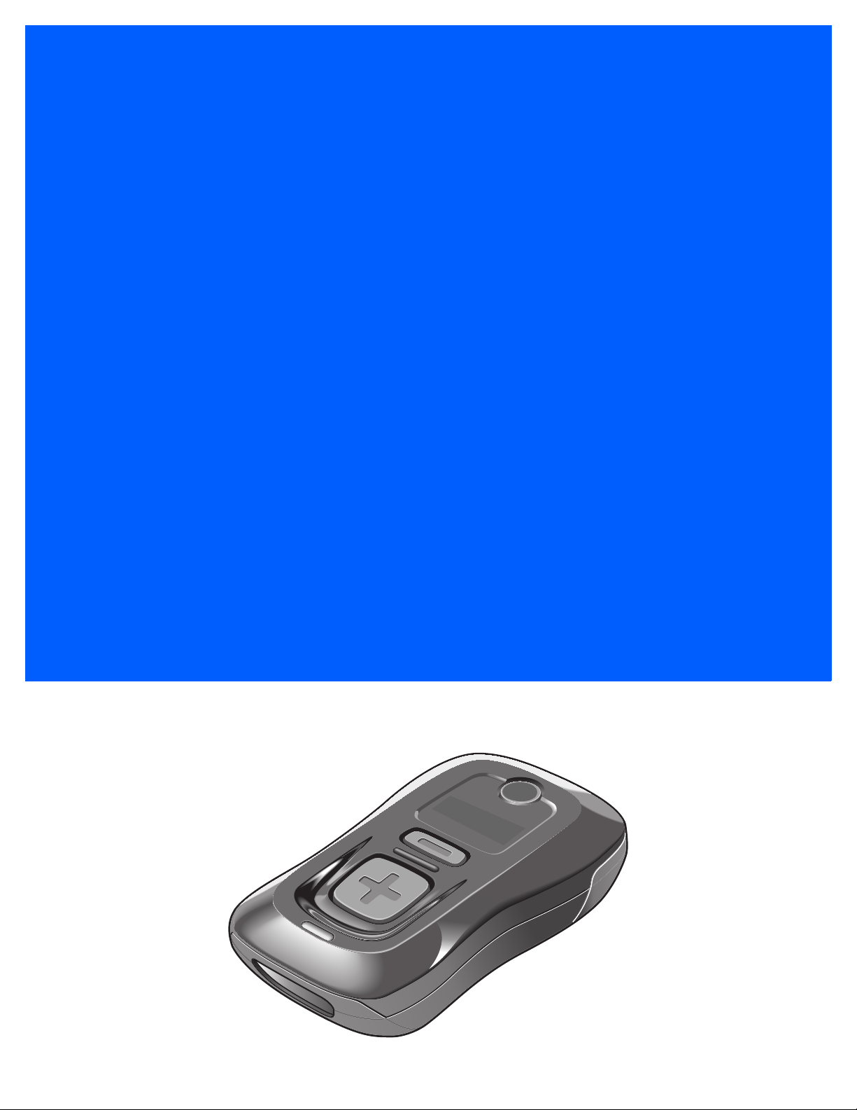
CS3000 SERIES
SCANNER
PRODUCT REFERENCE
GUIDE
Page 2

Page 3

CS3000 SERIES SCANNER
PRODUCT REFERENCE GUIDE
72E-136088-08
Revision A
May 2017
Page 4

ii CS3000 Series Scanner Product Reference Guide
No part of this publication may be reproduced or used in any form, or by any electrical or mechanical means,
without permission in writing. This includes electronic or mechanical mean s, such as ph otocop ying, re co rding,
or information storage and retrieval systems. The material in this manual is subject to chang e without notice.
The software is provided strictly on an “as is” basis. All software, including firmware, furnished to the user is on
a licensed basis. We grant to the user a non-transferable and non-exclusive license to use each software or
firmware program delivered hereunder (licensed program). Except as noted below, such license may not be
assigned, sublicensed, or otherwise transferred by the user with out our prior written consent. No right to copy a
licensed program in whole or in part is granted, except as permitted under copyright law. The user shall not
modify, merge, or incorporate any form or portion of a licensed program with other program material, create a
derivative work from a licensed program, or use a licensed program in a network without written permission.
The user agrees to maintain our copyright notice on the licensed prog rams delivered h ereunder, and to include
the same on any authorized copies it makes, in whole or in part. The user agrees not to decompile,
disassemble, decode, or reverse engineer any licensed program delivered to the user or any portion thereof.
Zebra reserves the right to make changes to any product to improve reliability, function, or design.
Zebra does not assume any product liability arising out of, or in connection with, the application or use of any
product, circuit, or application described herein. No license is granted, either expressly or by implication,
estoppel, or otherwise under any patent right or patent, covering or relating to any combination, system,
apparatus, machine, material, method, or process in which Zebra products might be used. An implied license
exists only for equipment, circuits, and subsystems contained in Zebra products.
Warranty
For the complete hardware product warranty statement, go to: http://www.zebra.com/warranty.
Page 5

Revision History
Changes to the original manual are listed below:
Change Date Description
-01 Rev A 07/2010 Initial release
-02 Rev A 10/2010 Added Motorola Droid Bluetooth connection example.
-03 Rev A 2/2012 Replaced specifications with link to specification/data sheet, added battery
-04 Rev A 2/2013 Updated out of range behavior description.
-05 Rev A 3/2015 Zebra Rebranding
iii
replacement note, add information for connecting to an iPad.
-06 Rev A 9/2015 Added items to config.ini table: Low Battery Indication and Performance,
Toggle, Maximum Bar Code Length;
Indications, Beeper Indications, and Troubleshooting tables; changed default
Beeper Volume to High; added Enable/Disable All Code Types parameter
-07 Rev A 2/2017 Updated parameter value in reference to Scan Data Transmission Format in
Setting Prefixes and Suffixes section, deleted statement after Character
Equivalents table
-08 Rev A 5/2017 Updated MOD 10/MOD 11 to MOD 11/MOD 10; GS1 DataBar-14 to GS1
DataBar Omnidirectional.
added software download issue to LED
Protect
Page 6

iv CS3000 Series Scanner Product Reference Guide
Page 7

TABLE OF CONTENTS
Warranty ......................................................................................................................................... ii
Revision History.............................................................................................................................. iii
About This Guide
Introduction..................................................................................................................................... xi
Product Reference Guide – Start Here..................................................................................... xi
Chapter Descriptions ...................................................................................................................... xi
Notational Conventions................................................................................................................... xii
Related Documents ........................................................................................................................ xiii
Service Information......................................................................................................................... xiii
Chapter 1: Getting Started
Introduction .................................................................................................................................... 1-1
Unpacking the Scanner .................................................................................................................. 1-2
The Cradle ..................................................................................................................................... 1-2
Connecting the Cradle ............................................................................................................. 1-2
Charging the Scanner Battery ........................................................................................................ 1-3
Charging via USB Host Cable .................................................................................................. 1-3
Charging via Charging Cradle .................................................................................................. 1-4
Scanner Charging LED ............................................................................................................ 1-5
Connecting to the Host Computer .................................................................................................. 1-5
Batch Connection ..................................................................................................................... 1-5
Bluetooth Connection: Development Options .......................................................................... 1-5
Bluetooth Connection Examples .............................................................................................. 1-6
Numeric Bar Codes for PIN Entry .................................................................................................. 1-24
Configuring the Scanner ................................................................................................................ 1-25
Staging Multiple Scanners ....................................................................................................... 1-25
Editing the Configuration File ................................................................................................... 1-26
Page 8

vi CS3000 Series Scanner Product Reference Guide
Chapter 2: Scanning
Introduction .................................................................................................................................... 2-1
Scanning ........................................................................................................................................ 2-1
Deleting Bar Codes .................................................................................................................. 2-2
Transmitting Bar Code Data to Host .............................................................................................. 2-2
Transferring Data from a Batch Scanner ................................................................................. 2-2
Transferring Data from an RF Scanner .................................................................................... 2-3
User Interface Definitions .............................................................................................................. 2-3
LED Indications ........................................................................................................................ 2-3
Beeper Indications ................................................................................................................... 2-6
Chapter 3: User Preferences
Introduction .................................................................................................................................... 3-1
Scanning Sequence Examples ...................................................................................................... 3-1
Errors While Scanning ................................................................................................................... 3-1
User Preferences Default Parameters ........................................................................................... 3-2
Reset ............................................................................................................................................. 3-4
Reset Factory Defaults .................................................................................................................. 3-4
Set Date and Time ......................................................................................................................... 3-5
Set Date ................................................................................................................................... 3-5
Set Time ................................................................................................................................... 3-5
Cancel Date and Time Setting ................................................................................................. 3-5
Numeric Bar Codes for Date and Time Settings ...................................................................... 3-6
Clear Data ...................................................................................................................................... 3-7
Beeper Settings ............................................................................................................................. 3-8
Beeper Volume ........................................................................................................................ 3-8
Beeper Tone ............................................................................................................................ 3-9
Mute Beeper ............................................................................................................................ 3-10
Scanner Options ............................................................................................................................ 3-11
Scan Angle ............................................................................................................................... 3-11
Transmit “No Read” Message .................................................................................................. 3-12
Bluetooth Options .......................................................................................................................... 3-13
Bluetooth Unpair ...................................................................................................................... 3-13
Bluetooth HID Profile ............................................................................................................... 3-13
Bluetooth Serial Port Profile (SPP) .......................................................................................... 3-13
Linear Code Type Security Level ................................................................................................... 3-14
Bi-directional Redundancy ............................................................................................................. 3-15
Data Options .................................................................................................................................. 3-16
Transmit Code ID Character .................................................................................................... 3-16
Prefix/Suffix Values .................................................................................................................. 3-17
Scan Data Transmission Format ............................................................................................. 3-18
Send Versions ............................................................................................................................... 3-20
Firmware Version ..................................................................................................................... 3-20
Bluetooth Version ..................................................................................................................... 3-20
Scan Engine Version ............................................................................................................... 3-20
Save Configuration ........................................................................................................................ 3-21
Page 9

Table of Contents vii
Chapter 4: Symbologies
Introduction .................................................................................................................................... 4-1
Scanning Sequence Examples ...................................................................................................... 4-1
Errors While Scanning ................................................................................................................... 4-1
Symbology Default Parameters ..................................................................................................... 4-2
Enable/Disable All Code Types ..................................................................................................... 4-5
UPC/EAN ....................................................................................................................................... 4-6
Enable/Disable UPC-A ............................................................................................................. 4-6
Enable/Disable UPC-E ............................................................................................................. 4-6
Enable/Disable UPC-E1 ........................................................................................................... 4-7
Enable/Disable EAN-8 ............................................................................................................. 4-7
Enable/Disable EAN-13 ........................................................................................................... 4-8
Enable/Disable Bookland EAN ................................................................................................ 4-8
Decode UPC/EAN Supplementals ........................................................................................... 4-9
User-Programmable Supplementals ........................................................................................ 4-13
Decode UPC/EAN Supplemental Redundancy ....................................................................... 4-13
Transmit UPC-A Check Digit ................................................................................................... 4-14
Transmit UPC-E Check Digit ................................................................................................... 4-14
Transmit UPC-E1 Check Digit ................................................................................................. 4-15
UPC-A Preamble ..................................................................................................................... 4-15
UPC-E Preamble ..................................................................................................................... 4-16
UPC-E1 Preamble ................................................................................................................... 4-17
Convert UPC-E to UPC-A ........................................................................................................ 4-18
Convert UPC-E1 to UPC-A ...................................................................................................... 4-18
EAN Zero Extend ..................................................................................................................... 4-19
Bookland ISBN Format ............................................................................................................ 4-20
UPC/EAN Security Level ......................................................................................................... 4-21
UCC Coupon Extended Code .................................................................................................. 4-22
Code 128 ....................................................................................................................................... 4-22
Enable/Disable Code 128 ........................................................................................................ 4-22
Enable/Disable GS1-128 (formerly UCC/EAN-128) ................................................................. 4-23
Enable/Disable ISBT 128 ......................................................................................................... 4-23
Lengths for Code 128 .............................................................................................................. 4-23
Code 39 ......................................................................................................................................... 4-24
Enable/Disable Code 39 .......................................................................................................... 4-24
Enable/Disable Trioptic Code 39 ............................................................................................. 4-24
Convert Code 39 to Code 32 (Italian Pharma Code) ............................................................... 4-25
Code 32 Prefix ......................................................................................................................... 4-25
Set Lengths for Code 39 .......................................................................................................... 4-26
Code 39 Check Digit Verification ............................................................................................. 4-27
Transmit Code 39 Check Digit ................................................................................................. 4-27
Enable/Disable Code 39 Full ASCII ......................................................................................... 4-28
Code 93 ......................................................................................................................................... 4-29
Enable/Disable Code 93 .......................................................................................................... 4-29
Set Lengths for Code 93 .......................................................................................................... 4-29
Code 11 ......................................................................................................................................... 4-31
Enable/Disable Code 11 .......................................................................................................... 4-31
Set Lengths for Code 11 .......................................................................................................... 4-31
Code 11 Check Digit Verification ............................................................................................. 4-33
Transmit Code 11 Check Digits ............................................................................................... 4-34
Interleaved 2 of 5 ........................................................................................................................... 4-34
Page 10

viii CS3000 Series Scanner Product Reference Guide
Enable/Disable Interleaved 2 of 5 ............................................................................................ 4-34
Set Lengths for Interleaved 2 of 5 ............................................................................................ 4-35
I 2 of 5 Check Digit Verification ................................................................................................ 4-37
Transmit I 2 of 5 Check Digit .................................................................................................... 4-37
Convert I 2 of 5 to EAN-13 ....................................................................................................... 4-38
Discrete 2 of 5 ................................................................................................................................ 4-38
Enable/Disable Discrete 2 of 5 ................................................................................................. 4-38
Set Lengths for Discrete 2 of 5 ................................................................................................ 4-39
Chinese 2 of 5 ................................................................................................................................ 4-40
Enable/Disable Chinese 2 of 5 ................................................................................................. 4-40
Codabar ......................................................................................................................................... 4-40
Enable/Disable Codabar .......................................................................................................... 4-40
Set Lengths for Codabar .......................................................................................................... 4-41
CLSI Editing ............................................................................................................................. 4-42
NOTIS Editing .......................................................................................................................... 4-42
MSI ................................................................................................................................................ 4-43
Enable/Disable MSI ................................................................................................................. 4-43
Set Lengths for MSI ................................................................................................................. 4-44
MSI Check Digits ..................................................................................................................... 4-45
Transmit MSI Check Digit ........................................................................................................ 4-45
MSI Check Digit Algorithm ....................................................................................................... 4-46
GS1 DataBar ................................................................................................................................. 4-46
Enable/Disable GS1 DataBar Omnidirectional (formerly GS1 DataBar-14) ............................ 4-46
Enable/Disable GS1 DataBar Limited ...................................................................................... 4-47
Enable/Disable GS1 DataBar Expanded ................................................................................. 4-47
Convert GS1 DataBar to UPC/EAN ......................................................................................... 4-48
Numeric Bar Codes ....................................................................................................................... 4-49
Cancel ............................................................................................................................................ 4-51
Chapter 5: Maintenance and Technical Specifications
Introduction .................................................................................................................................... 5-1
Maintenance .................................................................................................................................. 5-1
Troubleshooting ............................................................................................................................. 5-2
Technical Specifications ................................................................................................................ 5-4
Decode Zone ................................................................................................................................. 5-4
Appendix A: Standard Default Parameters
Appendix B: Programming Reference
Code Type IDs ............................................................................................................................... B-1
Symbol Code Identifiers ................................................................................................................. B-2
AIM Code Identifiers ...................................................................................................................... B-3
GS1-128 (formerly UCC/EAN-128) ................................................................................................ B-6
Setting Prefixes and Suffixes ......................................................................................................... B-7
Page 11

Table of Contents ix
Appendix C: Sample Bar Codes
UPC-A ............................................................................................................................................ C-1
UPC-E ............................................................................................................................................ C-1
UPC-E1 .......................................................................................................................................... C-2
EAN-13 .......................................................................................................................................... C-2
EAN-8 ............................................................................................................................................ C-2
Code 39 ......................................................................................................................................... C-2
Trioptic Code 39 ............................................................................................................................. C-3
Code 93 ......................................................................................................................................... C-3
Code 11 ......................................................................................................................................... C-3
Codabar ......................................................................................................................................... C-4
MSI ................................................................................................................................................. C-4
Interleaved 2 of 5 ........................................................................................................................... C-4
Index
Page 12

x CS3000 Series Scanner Product Reference Guide
Page 13

ABOUT THIS GUIDE
Introduction
The CS3000 Series Scanner Product Reference Guide provides general instructions for setting up, operating,
maintaining, and troubleshooting the scanner. The CS3000 series scanner is available in the following
configurations:
•
CS3000 - USB (batch), 0.5 GB Flash
•
CS3070 - USB (batch) and Bluetooth, 0.5 GB Flash
Each scanner includes a USB host cable. A charging cradle is also available for mounting, charging, and host
connection.
Product Reference Guide – Start Here
Go to the last page of this electronic manual and print it out. This is the Quick Start Instructions. This single page
provides links within the document to technical support for 99% of all customer questions.
Chapter Descriptions
Topics covered in this guide are as follows:
•
Chapter 1, Getting Started provides a product overview and describes how to charge, connect, and configure
the scanner.
•
Chapter 2, Scanning provides instructions for how to scan bar codes and send the data to a host, as well as
beeper and LED definitions.
•
Chapter 3, User Preferences describes each user preference feature and provides the programming bar
codes for selecting these features for the scanner. It also includes wireless communication parameters and
commonly used bar codes to customize how data is transmitted to the host device.
•
Chapter 4, Symbologies describes all symbology features and provides the programming bar codes for
selecting these features.
•
Chapter 5, Maintenance and Technical Specifications provides information on how to care for the scanner,
troubleshooting, and technical specifications.
Page 14
xii CS3000 Series Scanner Product Reference Guide
*Baud Rate 9600
Feature/Option
* Indicates Default
•
Appendix A, Standard Default Parameters provides a table of all host devices and miscellaneous
scanner defaults.
•
Appendix B, Programming Reference provides a table of AIM code identifiers, ASCII character
conversions, and keyboard maps.
•
Appendix C, Sample Bar Codes includes sample bar codes.
Notational Conventions
The following conventions are used in this document:
•
Italics are used to highlight the following:
• Chapters and sections in this and related documents
•
Bold text is used to highlight the following:
• Key names on a keypad
• Button names on a screen or window.
•
bullets (•) indicate:
• Action items
• Lists of alternatives
• Lists of required steps that are not necessarily seq ue nt ial
•
Sequential lists (e.g., those that describe step-by-step procedures) appear as numbered lists.
•
Throughout the programming bar code menus, asterisks (*) are used to denote default parameter
settings.
NOTE This symbol indicates something of special interest or importance to the reader. Failure to read the note
will not result in physical harm to the reader, equipment or data.
CAUTION This symbol indicates that if this information is ignored, the possiblity of data or material damage may
occur.
WARNING! This symbol indicates that if this information is ignored the possibility that serious personal
injury may occur.
Page 15

Related Documents
•
CS3000 Series Scanner Quick Reference Guide (p/n 72- 136598-xx) provides general information to help
the user get started with the scanner, including basic setup and operation instructions.
For the latest version of this guide and all guides, go to: http://www.zebra.com/support.
Service Information
If you have a problem using the equipment, contact your facility's technical or systems support. If there is a
problem with the equipment, they will contact the Zebra Global Customer Support Center at:
http://www.zebra.com/support.
When contacting Zebra support, please have the following information available:
•
Serial number of the unit
•
Model number or product name
•
Software type and version number
About This Guide xiii
Zebra responds to calls by e-mail, telephone or fax within the time limits set forth in service agreements.
If your problem cannot be solved by Zebra support, you may need to return your equipment for servicing and
will be given specific directions. Zebra is not responsible for any damages incurred during shipment if the
approved shipping container is not used. Shipping the units improperly can possibly void the warranty.
If you purchased your business product from a Zebra business partner, please contact that business partner
for support.
Page 16

xiv CS3000 Series Scanner Product Reference Guide
Page 17
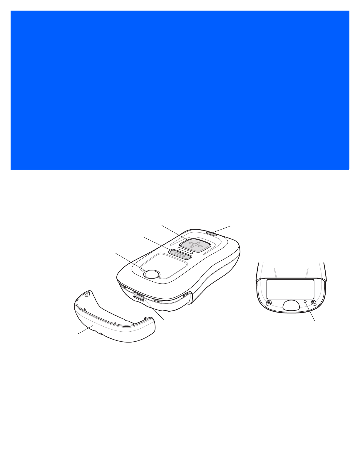
CHAPTER 1 GETTING STARTED
Mini-USB Port
Scan Button
LED
Bluetooth Button/LED
Delete Button
Protective Cover
Reset Button
Introduction
The CS3000 Series Scanner captures and stores bar codes for a variety of uses, and transmits bar code data
to a host via USB connection or Bluetooth.
Figure 1-1
This scanner supports the following host interfaces:
•
•
CS3000 Series Scanner
USB - The scanner connects to a USB host as a removable storage device, via a cradle or USB cable.
Bluetooth - The scanner supports Bluetooth HID connection to a host (the default) where the scanner
emulates a keyboard, as well as Serial Port Profile (SPP) connection where the scanner behaves as if
there is a serial connection.
Page 18
1 - 2 CS3000 Series Scanner Product Reference Guide
Unpacking the Scanner
Remove the scanner from its packing and inspect it for damage. If the scann er was damaged in tr ansit, contact
Zebra support. See page xiii for contact information. KEEP THE PACKING. It is the approved ship ping
container and should be used if the equipment ever needs to be returned for servicing.
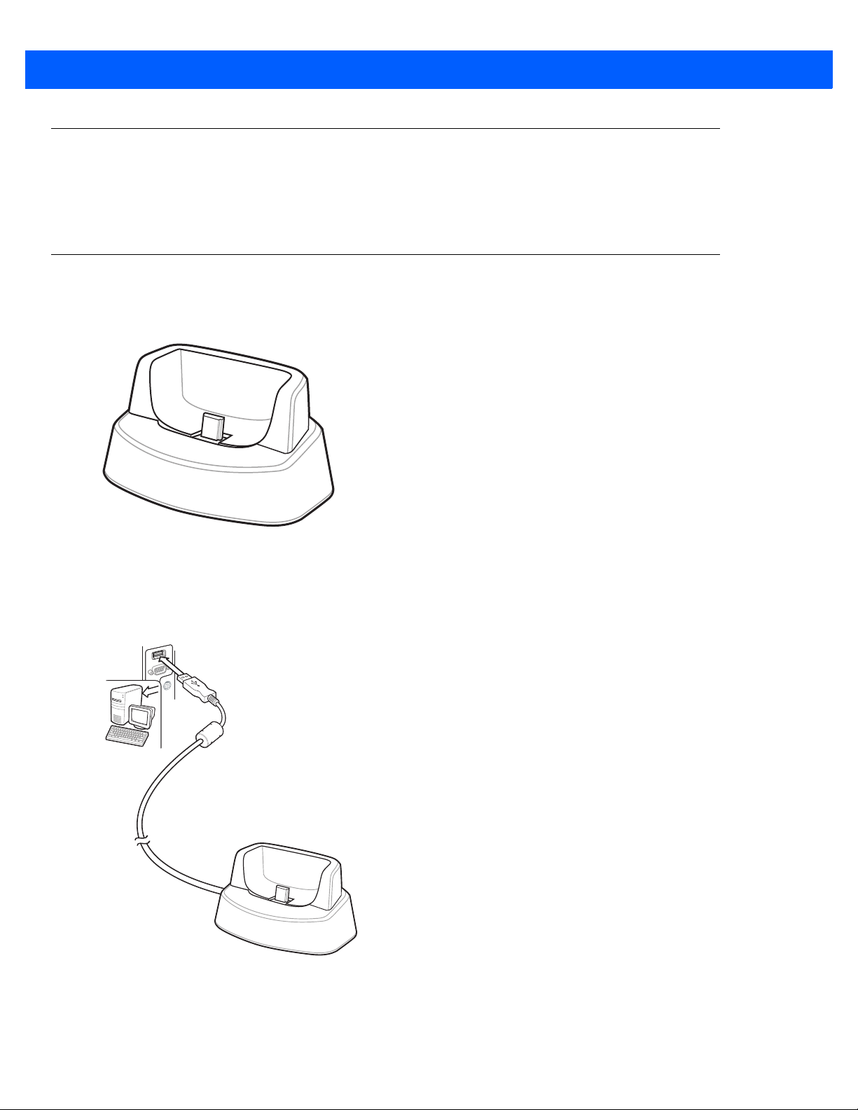
The Cradle
The cradle sits on a desktop and serves as a stand, charger, and USB communication device for the CS3000
series scanner. The cradle does not require a separate power sup ply to charge the scanner.
Figure 1-2
Cradle
Connecting the Cradle
Insert the cradle’s interface cable into a USB port on the host.
Figure 1-3
Connecting the Cables to the Cradle
Page 19
Charging the Scanner Battery
To charge the CS3000 series scanner, connect it to a host PC via the USB host cable or charging cradle. No
power supply is necessary. Charge time is approximately three hours for a fully discharged battery.
NOTE To check the battery charge status, hold the scan (+) button for 15 seconds. See Battery charge status in
Table 2-1 on page 2-3.
NOTE An authorized Zebra repair facility can replace the CS3000 battery. Changing the battery does not affect
bar code data which is stored in non-volatile memory, however the date and time is lost upon changing the
battery or if the battery completely loses charge.
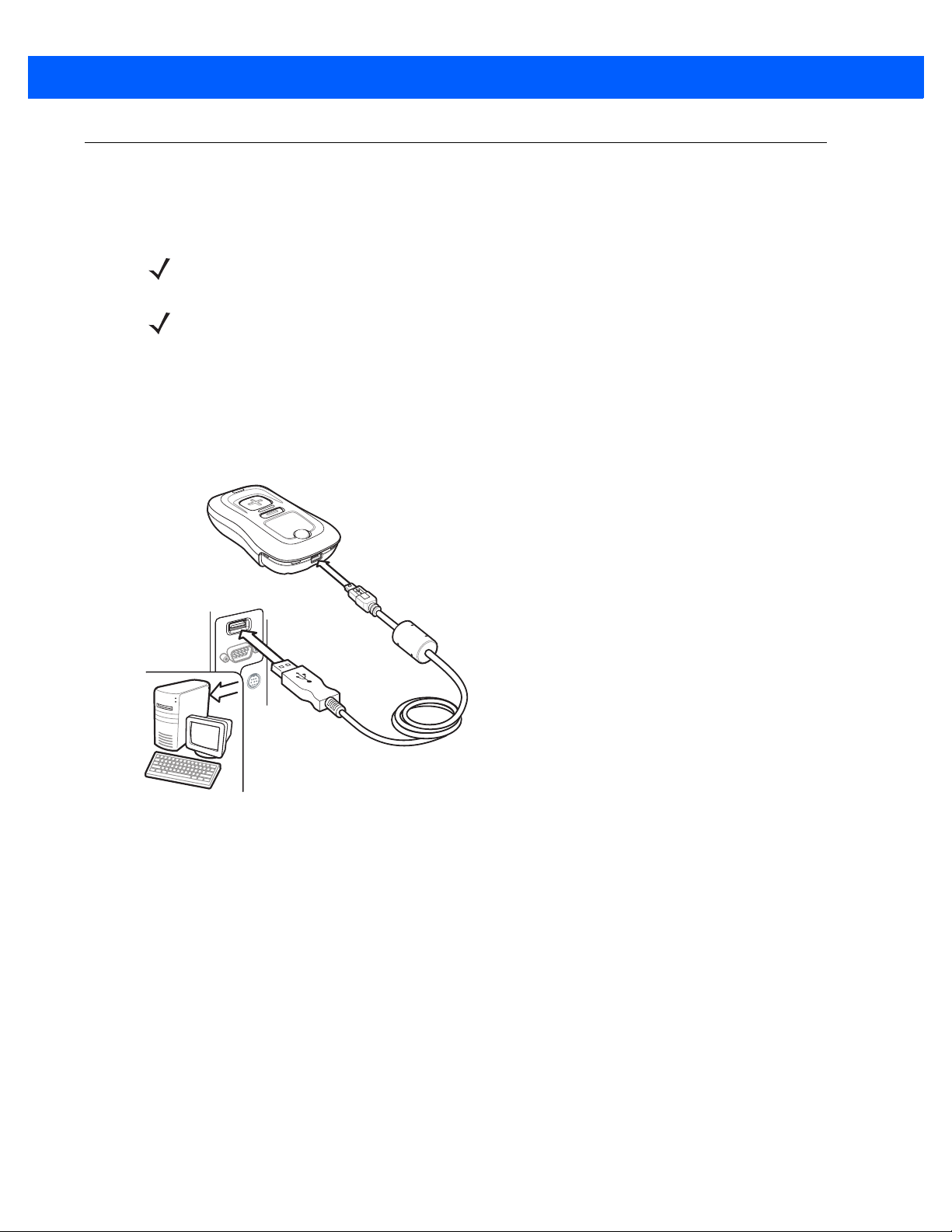
Charging via USB Host Cable
1. Insert the mini-USB connector on the host cable in the interface port on the scanner.
2. Connect the other end of the host cable to a USB port on the host PC.
Getting Started 1 - 3
Figure 1-4
The scanner begins charging. A complete charge of a fully discharged battery takes approximately three
hours. Charge within the recommended temperature of 32° to 104 ° F (0° to 40° C).
Connecting Scanner to Host PC
Page 20
1 - 4 CS3000 Series Scanner Product Reference Guide
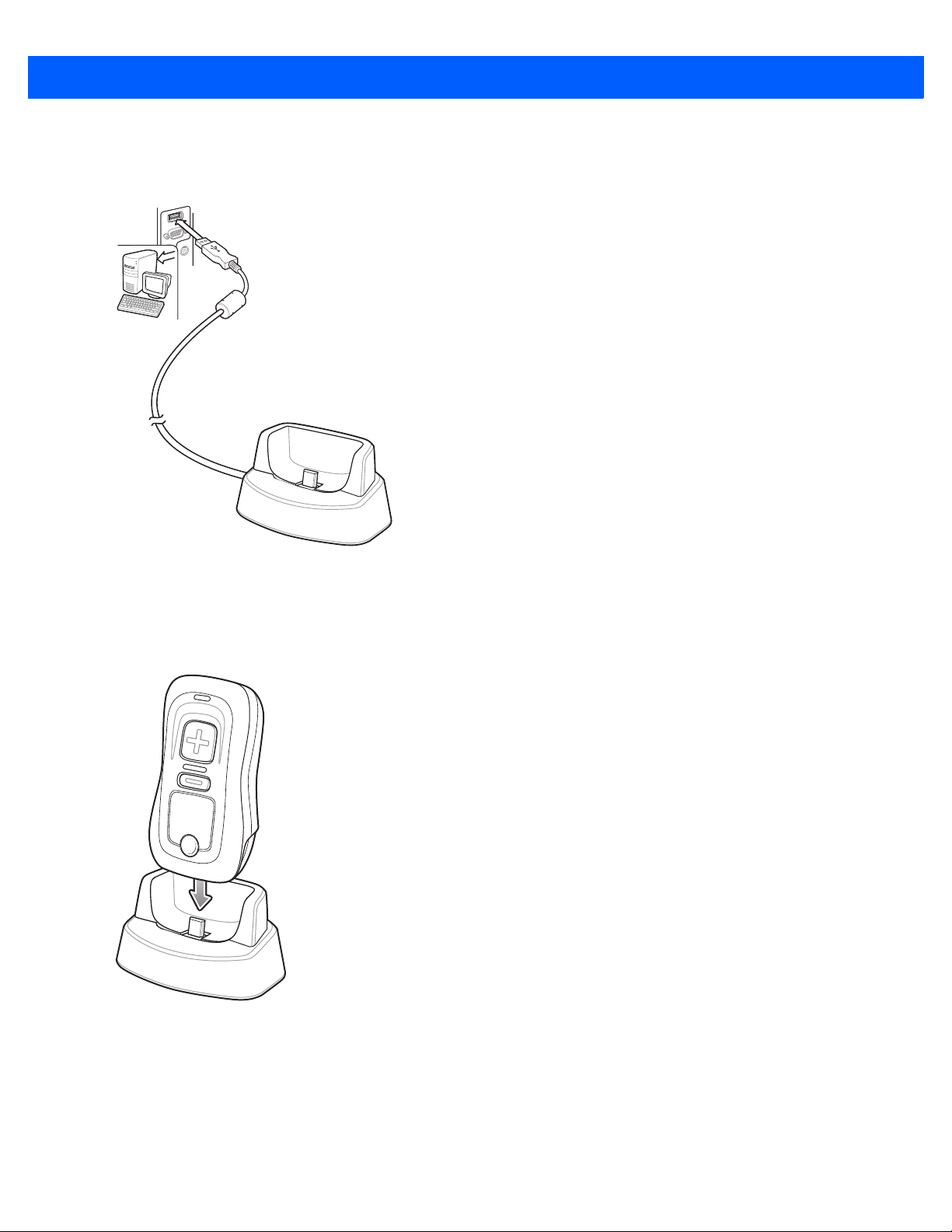
Charging via Charging Cradle
1. Insert the cradle’s USB connector into a USB port on the host PC.
Figure 1-5
2. Remove the protective cover from the scanner.
3. Place the scanner in the cradle, ensuring the mini-USB connector in the cradle inserts into the interface
port on the scanner.
Connecting Cradle to Host PC
Figure 1-6
The scanner begins charging. A complete charge of a fully discharged battery takes approximately three
hours. Charge within the recommended temperature of 32° to 104 ° F (0° to 40° C).
Inserting Scanner in Cradle
Page 21

Scanner Charging LED
The scanner’s LED indicates charging activity (see Table 2-1 on page 2-3). The amber LED blinks slowly
during charging. The scanner’s LED turns solid green when the battery is fully charged.
Connecting to the Host Computer
Batch Connection
See Charging the Scanner Battery on page 1-3 for instructions on connecting the scanner to a host PC via
USB.
NOTE To enter batch scanning mode, the scanner cannot be paired to a Bluetooth host (applies to CS3070
model only).
Bluetooth Connection: Development Options
Serial Port Profile
Getting Started 1 - 5
This Bluetooth profile emulates a serial cable to provide a simply implemented wireless replacement for
existing RS-232 based serial communications applications, including familiar control signals. It is the preferred
communication profile implementation because accidental key strokes from the keyboard or touch screen on
the host are not entered into the bar code dat a str ea m .
Human Interface Device Emulation
This Bluetooth profile is a lightweight wrapper of the Human Interface Device protocol defined for USB. Data
transmitted from the Bluetooth scanner appears as keyboard entries to the Bluetooth host (Smartphone, PC,
etc).
NOTE Wedge data appears within whichever application has input focus.
Page 22

1 - 6 CS3000 Series Scanner Product Reference Guide
Bluetooth Connection Examples
This section provides the following connection examples:
•
Droid X HID pairing Example
•
PC HID Pairing Example on page 1-7
•
PC SPP Pairing Example on page 1-10
•
Windows Mobile Device (ES400) HID Pairing Example on page 1-13
•
Windows Mobile Device (ES400) SPP Pairing Example on page 1-17
•
iPad Pairing Example on page 1-21
Overview
Pairing the CS3070 with a host device typically requires entering a pairing PIN on both the CS3070 and the
host device. To e nter th e PIN on th e CS3070, use the Numeric Bar Codes for PIN Entry on page 1-24. For the
host device, use the data entry method required for that device to enter the PIN.
Droid X HID Pairing Example
For CS3070 scanners, to pair to a Droid X via HID:
1. Press the scan button (+) to wake the scanner.
2. Press and hold the Bluetooth button (round button with logo) for five seconds. The scanner beeps and the
Bluetooth button starts blinking quickly to indicate that the scanner is discoverable by the host.
NOTE HID is the default profile for the CS3070. If this was changed, scan Bluetooth HID Profile on page 3-13.
3. On the Droid X, press the Settings button (bottom left hard button).
4. Tap Settings from the list of options that appears.
5. Tap Wireless & ne tworks.
6. Tap Bluetooth to enable Bluetooth.
7. Tap the Bluetooth settings option.
8. Tap Scan for devices. The CS3070 appears in the Bluetooth devices list, indicated by its model name and
serial number.
9. Select the CS3070 from the list. A window prompts for the PIN.
10. Tap the text box to open the soft keyboard. Enter the PIN using the keyboard and tap Ok.
11. With the CS3070, scan the PIN using the Numeric Bar Codes for PIN Entry on page 1-24 and scan Enter.
The scanner beeps to indicate it has paired with the Droid, and the Droid displays
Connected to hid below
the CS3070 device name.
To display scanned data on the Droid:
1. Tap and hold the screen to display the Add to Home screen menu.
2. Select widgets.
3. Scroll down the menu and select Sticky Note.
Page 23
Getting Started 1 - 7
4. Tap Sticky Note to display the text entry screen.
5. Tap in the text entry field and scan a bar code. The bar code contents appear in the text entry field.
PC HID Pairing Example
For CS3070 scanners, to pair to a Bluetooth-enabled PC or laptop via HID:
NOTE If the host does not support Bluetooth communication, a third-party Bluetooth adapter is required.
1. Press the scan button (+) to wake the scanner.
2. Press and hold the Bluetooth button (round button with logo) for five seconds. The scanner beeps and the
Bluetooth button starts blinking quickly to indicate that the scanner is discoverable by the host.
NOTE HID is the default profile for the CS3070. If this was changed, scan Bluetooth HID Profile on page 3-13.
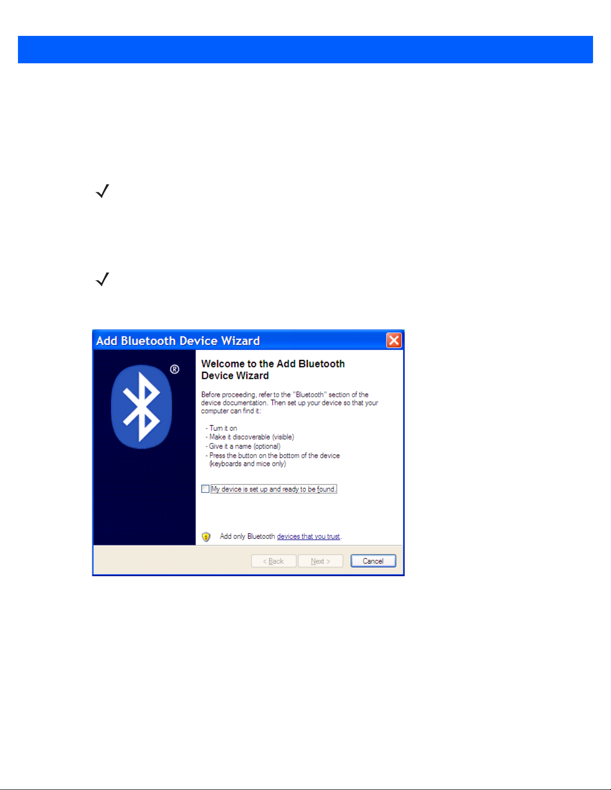
3. On the host PC, launch the third party Bluetooth pairing application. Following is a sample window of such
an application.
Figure 1-7
Sample Bluetooth Application Window
Page 24
1 - 8 CS3000 Series Scanner Product Reference Guide
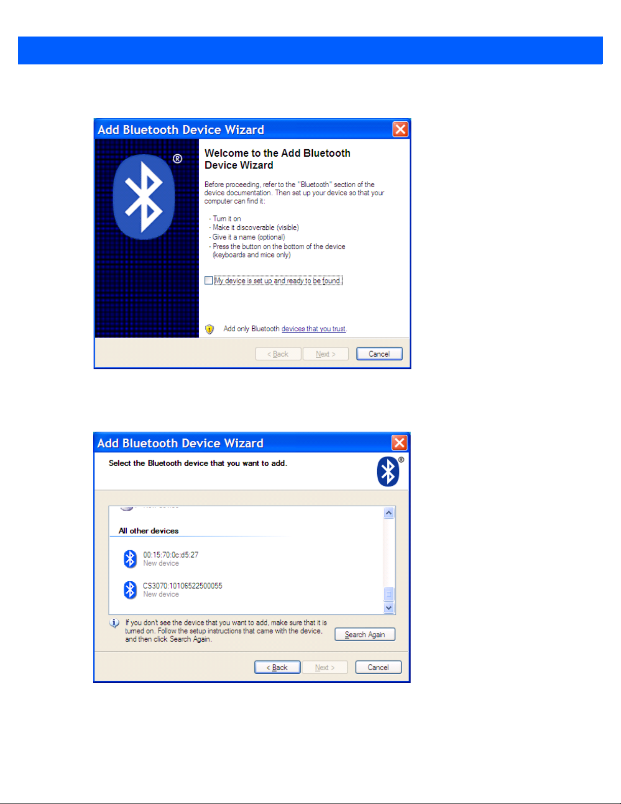
4. Place the application into discover Bluetooth device mode (in this example, select the check box), and click
Next.
Figure 1-8
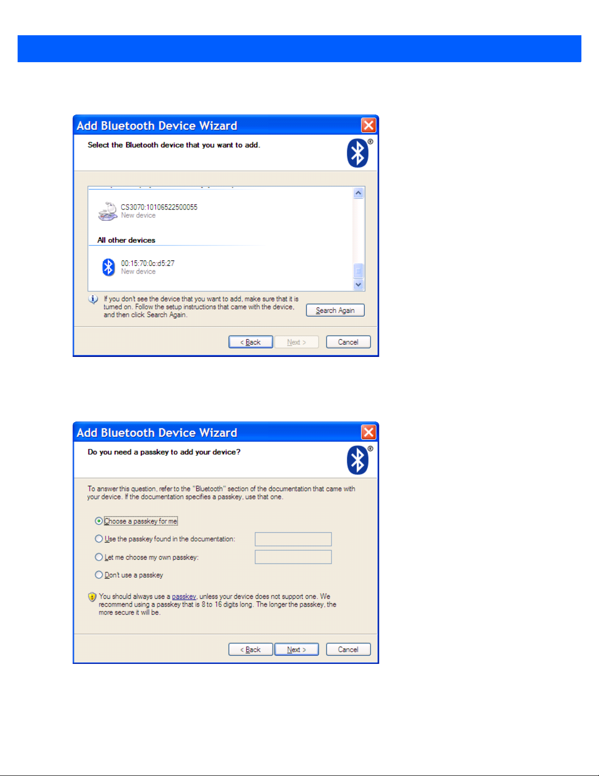
5. Select the CS3070 device from the discovered device list. The Bluetooth application may prompt you to
Sample Device Discovery Window
scan a passkey it generated, or for you to create and then scan a passkey (PIN).
Figure 1-9
Sample Passkey Option Window
Page 25
Getting Started 1 - 9
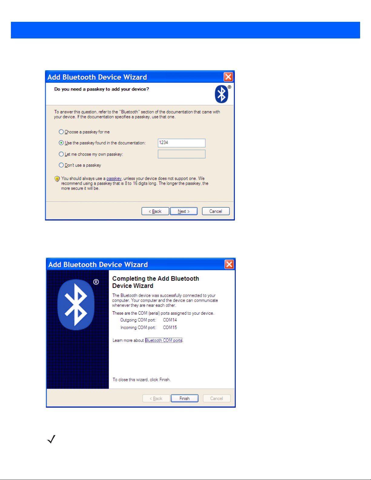
6. Select an option, then click Next:
•
If you select Choose a passkey for me, the host generates and displays a passkey.
•
If you select Use the passkey found in the documentation, enter the default 1234.
•
If you select Let me choose my own passkey, enter any passkey.
7. Scan Numeric Bar Codes for PIN Entry on page 1-24 corresponding to the passkey, then scan the Enter
bar code.
Figure 1-10
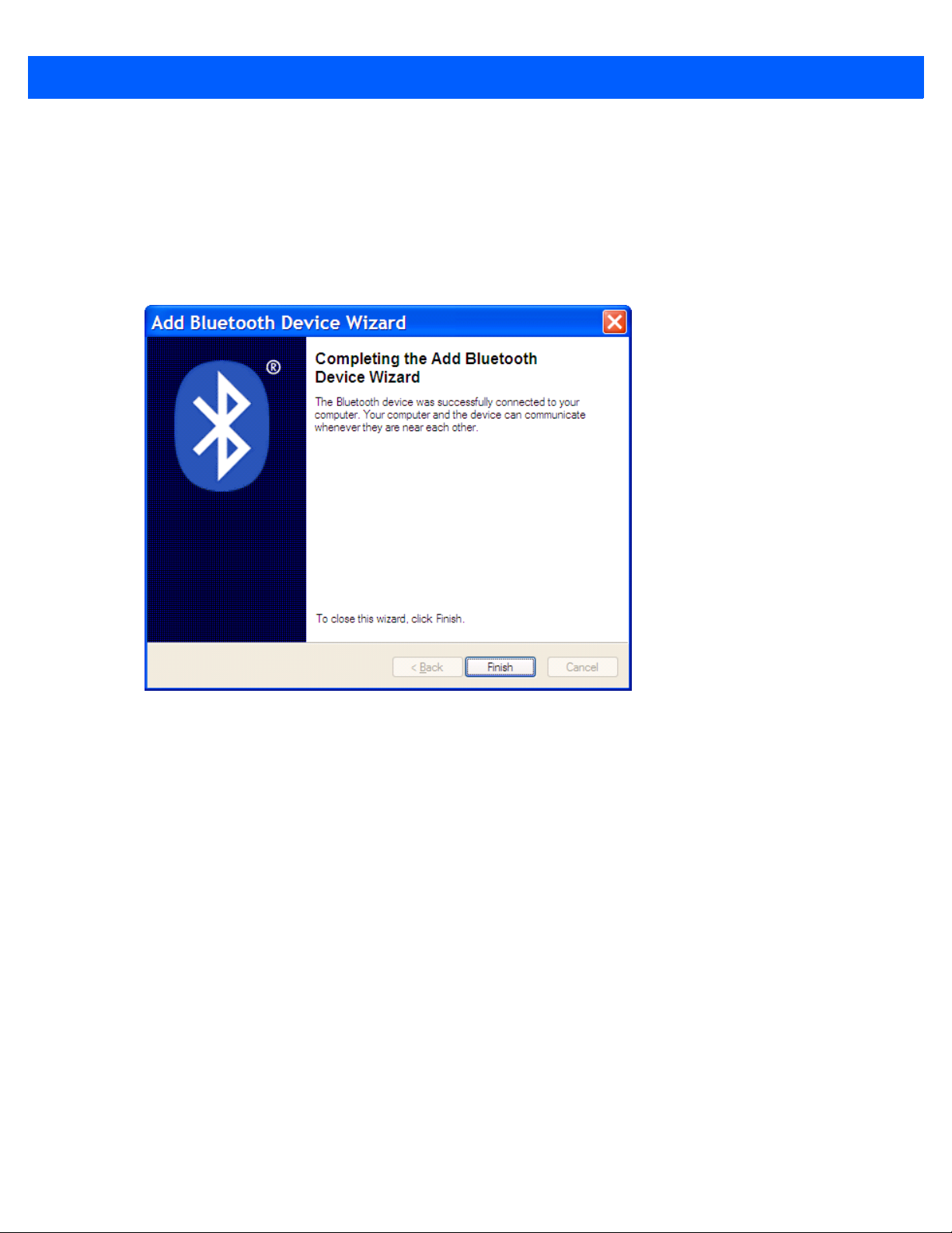
Sample Bluetooth Pairing Completion Window
Page 26
1 - 10 CS3000 Series Scanner Product Reference Guide
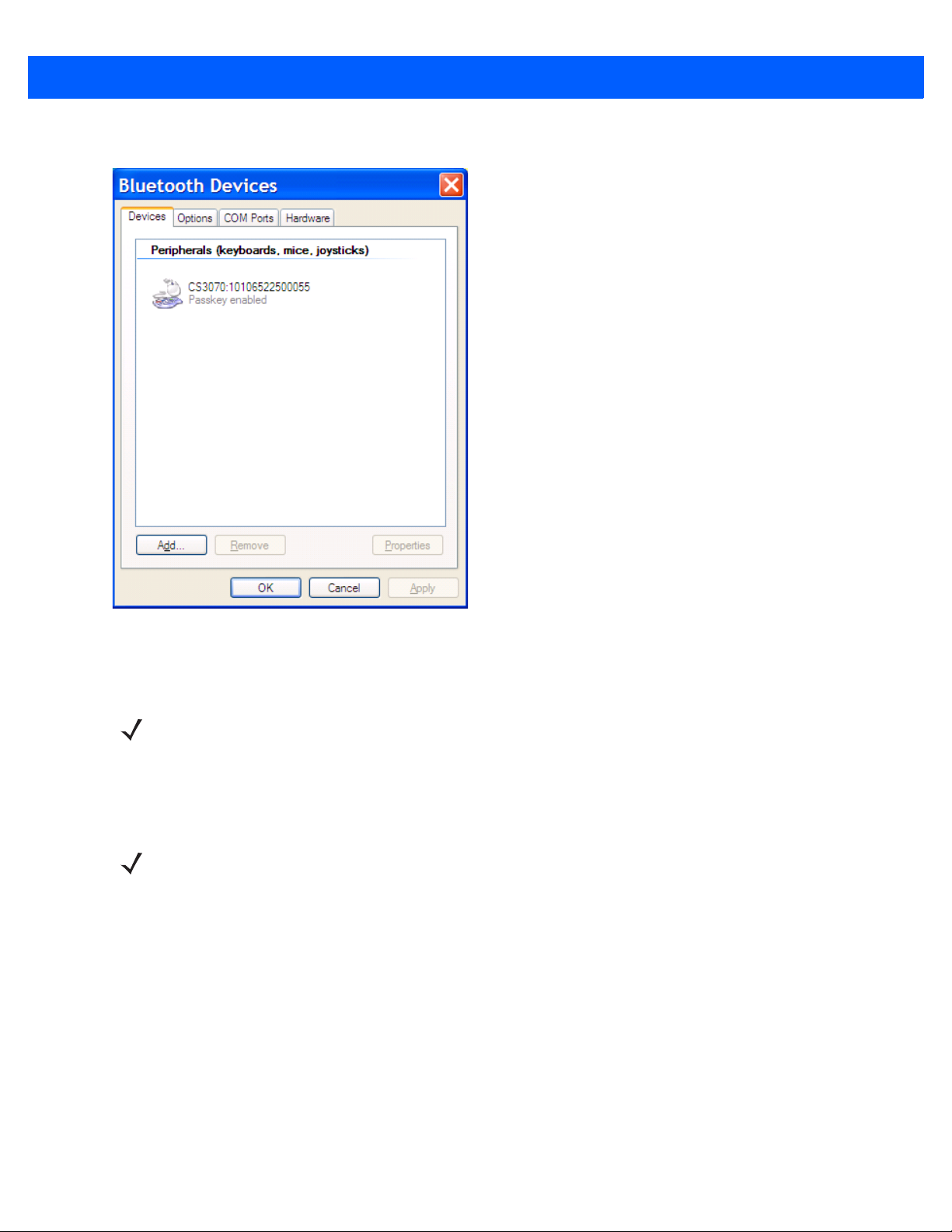
8. Click Finish to complete the pairing. The device appears in the Bluetooth Devices window.
Figure 1-11
9. Select the device, then click Add... The CS3070 issues a two-tone beep and the Bluetooth button blinks
Bluetooth Devices Window
slowly to indicate that the scanner paired with the host.
NOTE Bluetooth pairing suspends temporarily while charging via a USB cable. Disconnecting the cable
automatically re-establishes the Bluetooth pairing.
PC SPP Pairing Example
For CS3070 scanners, to pair to a Bluetooth-enabled PC or laptop via SPP:
NOTE If the host does not support Bluetooth communication, a third-party Bluetooth adapter is required.
1. Press the scan button (+) to wake the scanner.
2. Scan Bluetooth Serial Port Profile (SPP) on page 3-13. The Bluetooth button starts blinking quickly to
indicate that the scanner is discoverable by the host.
Page 27
Getting Started 1 - 11
3. On the host PC, launch the third party Bluetooth pairing application. Following is a sample window of such
an application.
Figure 1-12
4. Place the application into discover Bluetooth device mode (in this example, select the check box), and click
Next.
Sample Bluetooth Application Window
Figure 1-13
Sample Device Discovery Window
Page 28
1 - 12 CS3000 Series Scanner Product Reference Guide
5. Select the CS3070 device from the discovered device list. The Bluetooth application may prompt you to
scan a passkey it generated, or for you to create and then scan a passkey (PIN).
Figure 1-14
6. For SPP, select Use the passkey found in the documentation, then enter the default passkey 1234 in the text
box. Click
Sample Passkey Option Window
Next.
Figure 1-15
NOTE For SPP, the host requires entering a PIN, but no PIN entry is required for the CS3070.
Sample Bluetooth Pairing Completion Window
Page 29
Getting Started 1 - 13
7. Click Finish. In order to complete the pairing, open a serial input application such as HyperTerminal. The
CS3070 issues a two-tone beep and the Bluetooth button blinks slowly to indicate that the scanner paired
with the host.
NOTE Bluetooth pairing suspends temporarily while charging via a USB cable. Disconnecting the cable
automatically re-establishes the Bluetooth pairing.
Windows Mobile Device (ES400) HID Pairing Example
To pair to a ES400 Windows Mobile 6.5 device via HID:
1. Press the scan button (+) to wake the scanner.
2. Press and hold the Bluetooth button (round button with logo) for five seconds. The scanner beeps and the
Bluetooth button starts blinking quickly to indicate that the scanner is discoverable by the ES400.
NOTE HID is the default profile for the CS3070. If this was changed, scan Bluetooth HID Profile on page 3-13.
3. On the ES400, launch the third party Bluetooth pairing application. Following is a sample window of such
an application.
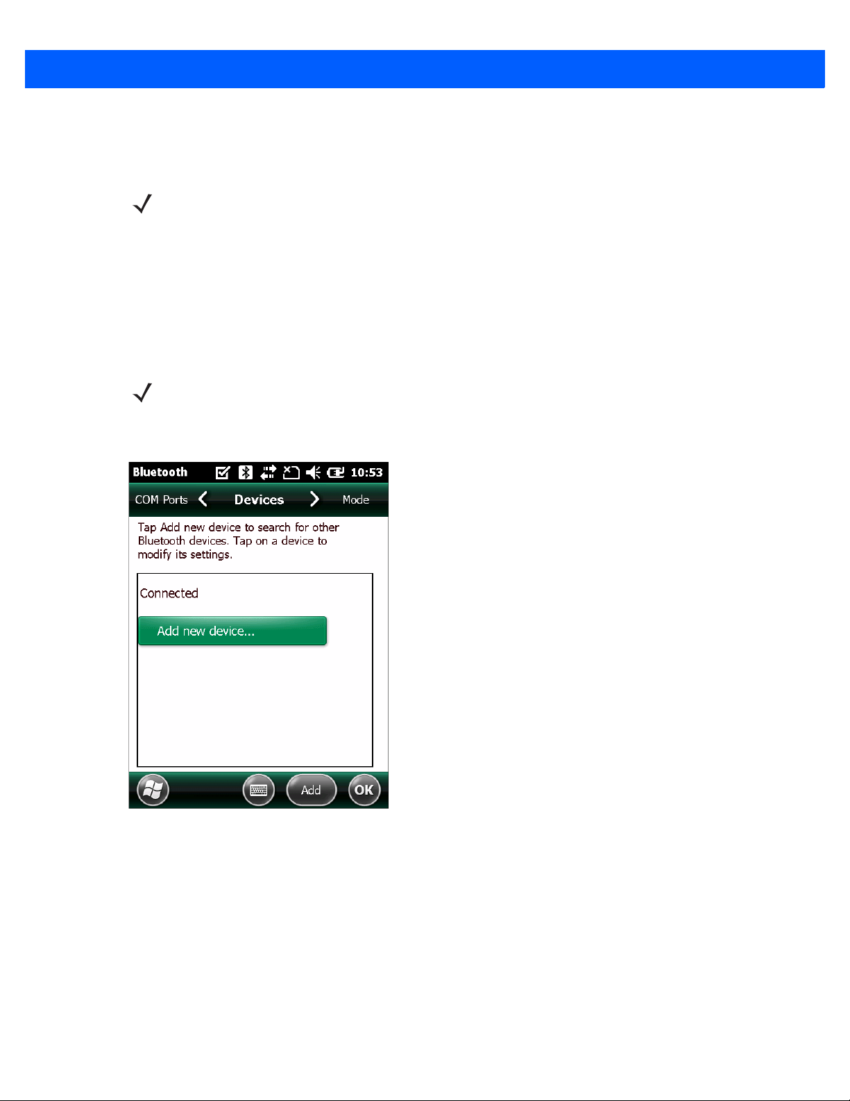
Figure 1-16
Sample Bluetooth Application - Add Device Window
Page 30
1 - 14 CS3000 Series Scanner Product Reference Guide
4. Tap Add new device.... The ES400 searches for Bluetooth devices.
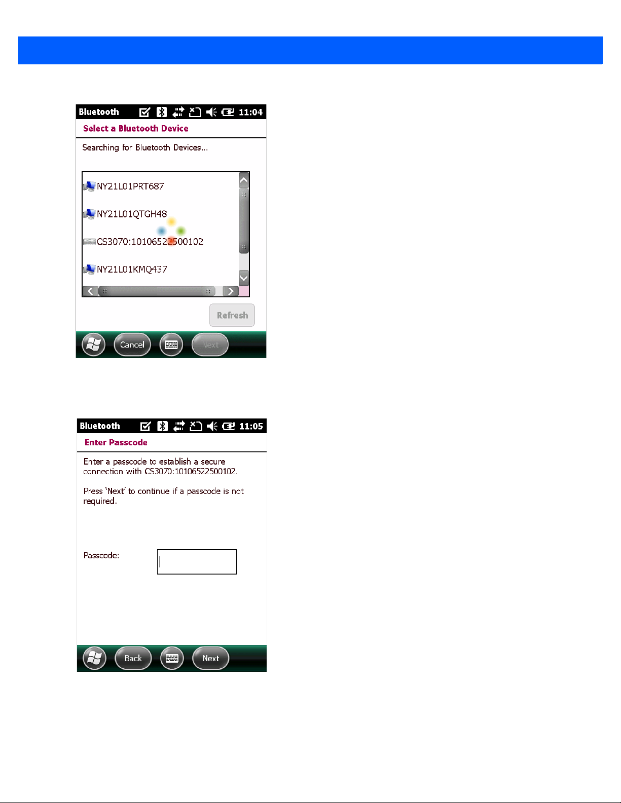
Figure 1-17
5. Select the CS3070 device from the discovered device list and tap Next. The device prompts you to enter a
Sample Device Discovery Window
passcode.
Figure 1-18
6. Tap Next if you don’t require a passcode, or enter any passcode and then tap Next.
Enter Passcode Window
Page 31

Getting Started 1 - 15
7. If you entered a passcode in Step 6, scan Numeric Bar Code s for PIN Entry on page 1-24 cor responding to
that code, then scan the
Enter bar code.
Figure 1-19
8. Select Yes on the pop-up window to add the device to the device list.
Connection Verification Window
Figure 1-20
Discovered Devices List
Page 32

1 - 16 CS3000 Series Scanner Product Reference Guide
9. Select the device and tap Connect to complete the pairing. The device appears in the Connected list, and
the CS3070 issues a two-tone beep and the Bluetooth button blinks slowly to indicate that the scanner
paired with the host.
Figure 1-21
NOTE Bluetooth pairing suspends temporarily while charging via a USB cable. Disconnecting the cable
Discovered Devices List
automatically re-establishes the Bluetooth pairing.
Page 33

Getting Started 1 - 17
Windows Mobile Device (ES400) SPP Pairing Example
For CS3070 scanners, to pair to a ES400 Windows Mobile 6.5 device via SPP:
1. Press the scan button (+) to wake the scanner.
2. Scan Bluetooth Serial Port Profile (SPP) on page 3-13. The Bluetooth button starts blinking quickly to
indicate that the scanner is discoverable by the ES400.
3. On the ES400, launch the third party Bluetooth pairing application. Following is a sample window of such
an application.
Figure 1-22
Sample Bluetooth Application Window - Add Device Window
Page 34

1 - 18 CS3000 Series Scanner Product Reference Guide
4. Tap Add new device.... The ES400 searches for Bluetooth devices.
Figure 1-23
5. Select the CS3070 device from the discovered device list and tap Next. The device prompts you to enter a
Sample Device Discovery Window
passcode.
Figure 1-24
Sample Enter Passcode Window
Page 35

6. Enter the CS3070 default PIN (1234) and tap Next.
Getting Started 1 - 19
Figure 1-25
7. Select Yes on the pop-up window to add the device to the device list.
Connection Verification Window
NOTE For SPP, on the host PC a PIN entry is required, but no PIN entry is required on the CS3070 device side.
Figure 1-26
Discovered Devices List
Page 36

1 - 20 CS3000 Series Scanner Product Reference Guide
8. Select the device and tap Connect. The Partnership Settings window appears.
Figure 1-27
9. Tap Serial Port and then Save to complete the pairing. The device appears in the Connected list, and the
Partnership Settings Window
CS3070 issues a two-tone beep and the Bluetooth button blinks slowly to indicate that the scanner paired
with the ES400.
Figure 1-28
NOTE Bluetooth pairing suspends temporarily while charging via a USB cable. Disconnecting the cable
Discovered Devices List
automatically re-establishes the Bluetooth pairing.
Page 37

Getting Started 1 - 21
iPad Pairing Example
For CS3070 scanners, to pair to an iPad:
1. Press the scan button (+) to wake the scanner.
2. Press and hold the Bluetooth button (round button with logo) for five seconds. The scanner beeps and the
Bluetooth button starts blinking quickly to indicate that the scanner is discoverable by the host.
NOTE HID is the default profile for the CS3070. If this was changed, scan Bluetooth HID Profile on page 3-13.
3. On the iPad, tap the Settings icon.
4. Tap General from the list of options that appears.
Figure 1-29
5. Tap Bluetooth. If Bluetooth is not enabled, swipe to enable it. The CS3070 appears in the Devices list,
General Menu
indicated by its model name and serial number.
Figure 1-30
Bluetooth Devices
Page 38

1 - 22 CS3000 Series Scanner Product Reference Guide
6. Select the CS3070 from the list. A window prompts for a PIN generated by the iPad.
Figure 1-31
7. With the CS3070, scan the PIN using the Numeric Bar Codes for PIN Entry on page 1-24 and scan Enter.
The scanner beeps to indicate it has paired with the iPad, and the iPad displays
Pin Prompt
Connected next to the
CS3070 device name.
To display scanned data on the iPad:
1. Tap the Notes icon to display the Notes text entry screen.
2. Scan a bar code. The bar code contents appear in the Note.
NOTE To enter keypad data with the scanned data, press the delete key ( - ) on the CS3070 to invoke the
keyboard on the iPad. Press this key again to toggle off the keyboard.
Figure 1-32
Note with Keyboard
Page 39

Getting Started 1 - 23
Unpairing
To temporarily unpair the scanner and host, press the Bluetooth button. This disables Bluetooth and the
Bluetooth button stops blinking. Pressing the Bluetooth button again re-pairs the scanner with the host.
To permanently unpair the scanner and host, scan Unpair on page 3-13. This allows the scanner to pair to a
different host device.
NOTE To enter batch scanning mode, the scanne r cannot be pai red to a Bluetooth host (applies to CS3070
model only).
Deleting the CS3070 from the Device List
To delete the device from the discovered devices list, tap and old the device and select Delete.
Figure 1-33
Deleting Device
Page 40

1 - 24 CS3000 Series Scanner Product Reference Guide
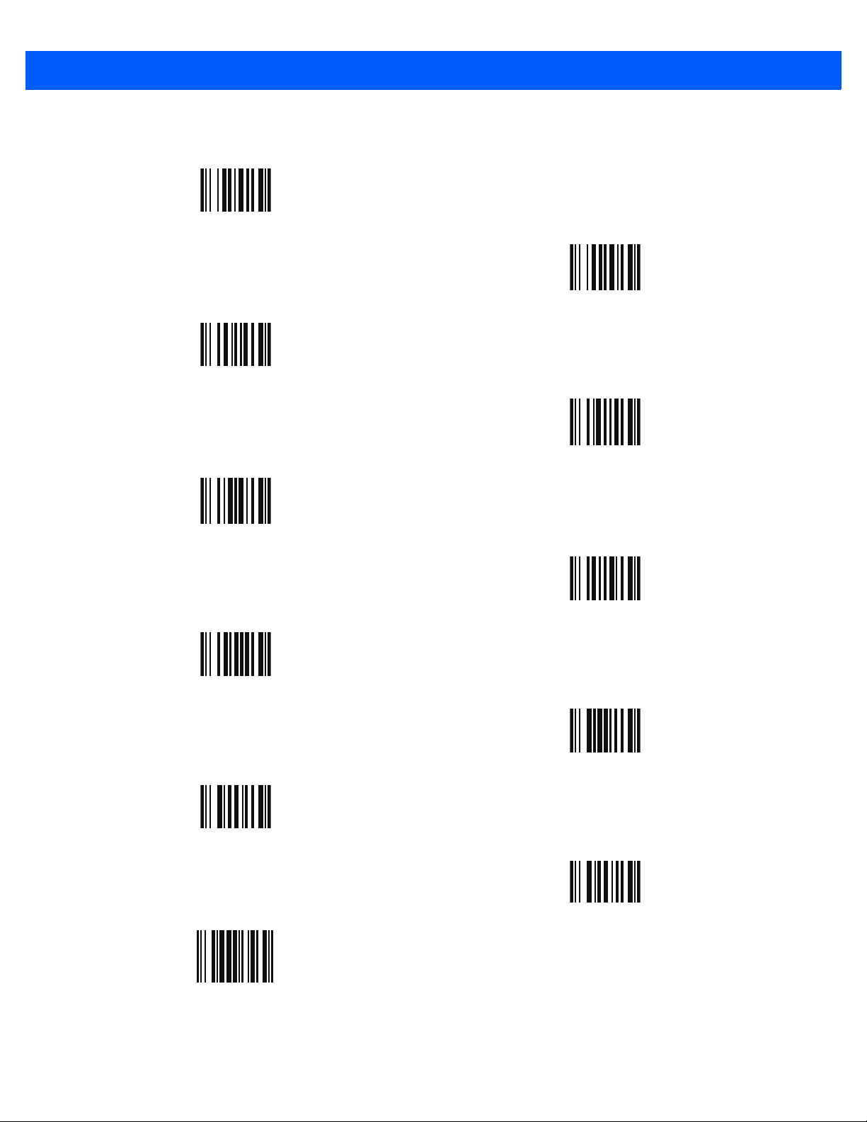
Numeric Bar Codes for PIN Entry
Use the following bar codes for pin entry for Bluetooth connection.
0
2
1
3
4
5
6
7
8
Enter
9
Page 41

Configuring the Scanner
To configure the scanner for initial use:
1. Scan the parameter bar codes in Chapter 3, User Preferences and Chapter 4, Symbologies to customize
scanner operation.
2. Scan the Save Configuration bar code on page 3-21 (also provided below).
NOTE When scanning parameter bar codes, scan each bar code within two minutes of the previous one. The
scanner enters sleep mode after two minutes of inactivity, and any parameter bar codes scanned and not
saved are ignored.
3. For additional customization, edit the Config.ini file on the scanner using the options in Editing the
Configuration File on page 1-26.
Getting Started 1 - 25
Save Configuration
4. CS3070 only: When deploying the new configuration to multiple scanners, to ensure unique CS307 0 serial
numbers appear in the host’s discovery window, edit the
Config.ini file to either remove the BTName entry
or set it to blank (“BTName=”) to ensure that each scanner uses the default BT name of
CS3070:<serial number>.
Staging Multiple Scanners
After creating a config.ini file for one “golden” scanner with all desired settings, create a copy of the file from
this scanner and copy it to other scanners via USB connection. Set the time and date on the “cloned” scanners
by scanning bar codes from Set Date and Time on page 3-5.
NOTE CS3070 only: When deploying the new configuration to multiple scanners, to ensure unique CS3070
serial numbers appear in the host’s discovery window, edit the Config.ini file to either remove the
BTName entry or set it to blank (“BTName=”) to ensure that each scanner uses the default BT name of
CS3070:<serial number>.
NOTE Before deploying the Config.ini file to multiple scanners, make the file read only to prevent users from
overwriting the file when scanning Save Configuration or Reset Factory Defaults on page 3-4.
Page 42

1 - 26 CS3000 Series Scanner Product Reference Guide
Editing the Configuration File
Use a text editor such as Notepad to set configuration values in the Config.ini editable text file in the
\Parameters folder on the CS30XX. Table 1-1 lists the programmable contents of the file.
NOTE If you make errors while editing the Config.ini file, the file LOG.TXT is created in the \Parameters folder.
Consult this log file to determine the errors and make corrections.
Table 1-1
Config.ini File Content
Parameter Values Description Default
BarcodeFile String In batch mode, the name of the batch file
BARCODES.TXT
containing bar codes scanned.
BarcodeDB String Bar code database filename. If the
DBASE.TXT
database file exists scanned bar codes are
checked against its content. If the bar
code exists within the database, the
scanner issues a positive beep, if not a
negative beep. To engage this mode,
create the BarcodeDB.txt file on the
CS30XX. Note that if this mode is
engaged, no bar code data is saved to the
scanner.
BTPin String Default SPP PIN. 1234
BTName String Bluetooth device name (address) used
during discovery.
BTProfile HID
Selected BT profile. HID
CS3070:<serial
number>
SPP
Mute On
Mute the beeper. Off
Off
Prefix Character Prefix character. <none>
Suffix Character Suffix character. 0x0D (CR)
Separator Character Separator character. ','
DateFormat MM/DD/YY
DD/MM/YY
MM/DD/YYYY
DD/MM/YYYY
TimeFormat 12h
24h
Date format for batch data. Set to enable
date stamp
. See
Set Date on page 3-5
to
set the date.
Enter no value to disable the date stamp,
for example: “
DateFormat =
“
Time format for batch data. Set to enable
time stamp
. See
Set Time on page 3-5
to
MM/DD/YY
(Enabled)
24h
(Enabled)
set the time.
Enter no value to disable the time stamp,
for example: “
Sleep Integer Time in seconds before the scanner ent ers
TimeFormat =
“
120 (2 minutes)
sleep mode when no activity is detected.
Page 43

Getting Started 1 - 27
Table 1-1
BTSleep Integer Time in seconds before the scanner ent ers
ButtonPlus Enabled
ButtonMinus Enabled
ButtonBT Enabled
WakeUpLED Enabled
LEDBlue Enabled
LEDGreen Enabled
LEDRed Enabled
Config.ini File Content (Continued)
Parameter Values Description Default
600 (10 minutes)
sleep mode while paired to another
Bluetooth device when no activity is
detected.
Enable or disable the Plus button. Enabled
Disabled
Enable or disable the Minus button. Enabled
Disabled
Enable or disable the BT button. Enabled
Disabled
Enable or disable the wake-up LEDs. Disabled
Disabled
Disabled
Disabled
Disabled
Enable or disable the blue LED for normal
operation and wake up.
Enable or disable the green LED for
normal operation and wake up
Enable or disable the red LED for normal
operation and wake up.
Enabled
Enabled
Enabled
LEDAmber Enabled
Disabled
ScanLED Enabled
Disabled
Low Battery
Indication and
Performance
Protect Toggle 0 = Disable
0 = Disable low
battery indication
and performance
1 = Disable low
battery indication,
enable
performance
2 = Enable low
battery indication,
disable
performance
3 = Enable low
battery indication
and performance
1 = Enable
Enable or disable the amber LED for
normal operation and wake up.
Enable or disable the LEDs that illuminate
while the laser scanner is active.
See
Table 2- 1
battery indications for this parameter.
See
Table 2- 1
Protection. Enable or disable the ability to
toggle the Data Protection feature on and
off.
for a description of low
under Toggle Data
Enabled
Enabled
3 = Enable low battery
indication and
performance
Disable
Page 44

1 - 28 CS3000 Series Scanner Product Reference Guide
Table 1-1
ScanParam Variable Any scan engine parameter. Multiple
CodeID Enabled
Maximum Bar
Code Length
Config.ini File Content (Continued)
Parameter Values Description Default
<none>
entries are allowed. Sent after reset or
when engine is powered.
For example:
ScanParam=0xf0,0x00,0x01
ScanParam=0xee,0x01
ScanParam=0x38,0x00
Enable or disable saving CodeID in the
Disabled
Integer Maximum length of a bar code that can be
scanned bar codes file. See
IDs on page B-1
scanned and transmitted to host.
.
Code Type
Enabled
60
Page 45

CHAPTER 2 SCANNING
012345
WRONG
012345
RIGHT
Introduction
This chapter provides instructions for how to scan bar codes and send the data to a host. Beeper and LED
definitions are also included.
Scanning
See Chapter 1, Getting Started to install and program the scanner. To scan:
1. Aim the scanner at the bar code.
2. Press the scan (+) button.
Figure 2-1
3. Ensure the scan line crosses every bar and space of the symbol.
Scanning
Page 46

2 - 2 CS3000 Series Scanner Product Reference Guide
4. The scanner beeps and the LED turns green to indicate a successful deco de. See Table 2-1 and Table 2-2
for beeper and LED definitions.
NOTE The scanner cannot scan bar codes when it is connected to the host via the USB host cable.
Deleting Bar Codes
In batch mode, to delete a bar code aim the scanner at the bar code and press the delete ( - ) button.
Figure 2-2
Deleting a Bar Code in Batch Mode
NOTE Bar codes cannot be deleted in Bluetooth mode.
Transmitting Bar Code Data to Host
Transferring Data from a Batch Scanner
The BarcodeFile.txt file within the \Scanned Barcodes directory on the scanner stores scanned bar code data.
Connect the scanner to the host PC via USB host cable or the charging cradle and use Windows Explorer to
navigate to the scanner. Copy the bar code data file to the host
To clear the bar code data, delete the BarcodeFile.txt file from the scanner, or scan the
page 3-7.
Autorun Feature
The scanner supports an autorun feature where you can build an autorun.in f file to auto matically copy the data
to the host upon connection. Autorun.inf is a text-based configuration file that defines, upon connecting the
scanner, which executable or application to run on the host, which icon represents the scanner, and which
menu commands appear when you right-click the scanner icon from Windows Explorer. For more information,
search
autorun.inf on any search engine.
Clear Data bar code on
Page 47

Transferring Data from an RF Scanner
When the scanner is paired to a host via Bluetooth, data transmits to the host after each scan and is not stored
on the device.
Out of Range Behavior
If the scanner moves out of range of the host, and does not re-pair with the host within the timeout period,
scanned data is lost and the scanner emits a 3-beep error tone.
When the radio loses connection, the Bluetooth LED stops its slow, consistent blinking and the beeper emits a
short high low beep. The Bluetooth LED blinks at a faster rate for a period of time while the device attempts to
reestablish pairing with the host, and when it returns within ra ng e the de vic e re pa irs. If repairing is
unsuccessful the Bluetooth LED stops blinking.
To manually reestablish paring when the device returns to range, press the Bluetooth LED button. Upon
Bluetooth pairing, the beeper emits a short low high beep and the Bluetooth LED starts its slow, consistent
blinking again.
User Interface Definitions
Scanning 2 - 3
The scanner uses beeper and LED sequences to indicate various system events. Table 2-1 and Table 2-2
define these sequences and events.
LED Indications
Table 2-1
Scan attempt Press scan (+) button Flashing green Laser on
Successful bar code scan Solid green Laser off
Battery charge status Hold scan (+) button 15
Delete bar code
(when in batch mode)
LED Indications
Function Performed User Action LED Feedback Other
Flashing green Full charge (for 8 hours
seconds
Press & hold delete (-)
button
Flashing amber Less than 8 hours but
Flashing red Less than 1 hour of
Flashing amber Laser on
at 6 scans per minute)
more then one of
operating time
operating time
Successful bar code deletion Solid amber Laser off
Unsuccessful deletion - item
doesn't exist (when in batch
mode)
Solid red Laser off
Page 48

2 - 4 CS3000 Series Scanner Product Reference Guide
Table 2-1
Clear all bar code data
(when delete (-) button enabled)
Successful clear all Solid amber Laser off
Charge scanner Connect scanner to a
Charge complete Solid green
Toggle data protection on or off
(when enabled)
Successful data protection setting Solid amber
Enable Bluetooth radio Hold Bluetooth button
Bluetooth radio pairing Press Bluetooth button Slowly flashing blue
LED Indications (Continued)
Function Performed User Action LED Feedback Other
Press & hold delete (-)
button 3 seconds past
scan time
host PC USB port
Press & hold both scan
(+) and delete (-)
buttons for 6 seconds
for 5 seconds
Flashing amber Laser on
Flashing amber Scanner connects in
mass storage mode,
auto-run application on
PC launches
None
Rapidly flashing blue
LED
LED
Bluetooth is enabled but
has not paired with a
host
Bluetooth radio paired with host
and in range
Bluetooth radio out of range of
host
Bluetooth radio returns to
communication range of host
Special Conditions
Memory low scan Press & hold scan (+)
Delete/Clear All Press & hold delete (-)
Memory Full Scan Press & hold scan (+)
Memory Full Delete/Clear All Press & hold delete (-)
Press any button Very slowly flashing
button
button
button
button
Very slowly flashing
blue LED
Blue LED is off Stops transmitting
beacons
Re-pairs device with
blue LED
Flashing red, then
normal operation
Normal operation
Solid red
Normal operation
host
Page 49

Scanning 2 - 5
Table 2-1
Battery low indication - Scan Delete/Clear All
Battery depleted Scan/function/dock None
Data protection (enabled and on) Scan/function/ host com Rapidly flashing red
Unexpected failure Scan/function/dock Flashing red, green
Failed software download Live software download
LED Indications (Continued)
Function Performed User Action LED Feedback Other
When enabled Normal operation Solid red, then
normal operation
When enabled and
performance disabled
When disabled and
performance enabled
When disabled and
performance disabled
Normal operation Solid red for 3
seconds
Normal operation Normal operation
Normal operation None No decode or upload
and amber for 5
seconds
Flashes red for 5
update with software
version equal or prior to
PAABCX00-011-RXX
(i.e., <= 01 1) on scanner
with Spansion flash part.
Load software greater
than or equal to
PAABCS00-012-RXX
(i.e., >= 012).
seconds after
removing the USB
cable
No decode or upload
Contact support
Scanner indicates the
download is proceeding
normally for a second or
two (i.e., LED blinks red
and green), then fails
because software
(<= 011) is not
compatible with the new
Spansion flash part.
Page 50

2 - 6 CS3000 Series Scanner Product Reference Guide
Beeper Indications
Table 2-2
Successful bar code scan Short high tone Laser off
Successful bar code deletion Short medium tone Laser off
Unsuccessful deletion - item doesn't
exist (when in batch mode)
Successful clear all 2 long medium tones Laser off
Successful data protection setting Short long short
Connect scanner to a host PC USB
port to charge scanner
Enable Bluetooth radio Short beep Hold Bluetooth button for 5 seconds
Bluetooth radio pairing Short low high
Bluetooth radio out of range of host Short high low Stops transmitting beacons
Bluetooth radio returns to
communication range of host
Attempt to scan when out of
Bluetooth radio range
Beeper Indications
Function Performed Beeper Feedback Other
Long short short Laser off
Low high
Short low high Re-pairs device with host
4 high tones No Bluetooth transmission
Memory Full Scan Long tones for 5 seconds or
until scan button released
Failed software download 5 high short beep tones after
removing the USB cable
Scanner indicates the download is
proceeding normally for a second or
two (i.e., LED blinks red and green),
then fails because software (<= 011)
is not compatible with the new
Spansion flash part.
Page 51

CHAPTER 3 USER PREFERENCES
*High Frequency
Feature/Option
* Indicates Default
Introduction
This chapter describes each user preferen ce fea tu re and provides the programming bar codes for selecting
these features for the scanner.
The scanner ships with the settings shown in the User Preferences Default Table on page 3-2 (also see
Appendix A, Standard Default Parameters for all host device and miscellaneous scanner defaults). If the
default values suit the requirements, programming is not necessary. To change these values, scan a single bar
code or a short bar code sequence. After scanning Save Configuration on page 3-21, the new settings are
stored in non-volatile memory and are preserved when the scanner powers down.
To return all features to their default values, scan the Reset Factory Defaults bar code on page 3-4. Throughou t
the programming bar code menus, default values are indicated with asterisks (
*).
Scanning Sequence Examples
Errors While Scanning
In most cases, scan only one bar code to set a parameter value. For example, to set the beeper tone to high,
scan the High Frequency (beeper tone) bar code under Beeper Tone on page 3-9. The scanner issues a fast
warble beep and the LED turns green, indicating a successful parameter entry.
Other parameters, such as Data Transmission Formats, require scanning several bar codes. See the
parameter description for this procedure.
Unless otherwise specified, if an error is made during a scanning sequence, re-scan the correct parameter.
Page 52

3 - 2 CS3000 Series Scanner Product Reference Guide
User Preferences Default Parameters
Table 3-1 lists the defaults for user preference parameters. To change any option, scan the appropriate bar
code(s) provided in this chapter.
NOTE See Appendix A, Standard Default Parameters for all default parameters.
Table 3-1
Reset N/A
Reset Factory Defaults N/A
Set Date N/A
Set Time N/A
Cancel Date and Time Settings N/A
Clear Data N/A
Beeper Volume 0x8C High
Beeper Tone 0x91 Me dium Frequency
Mute Beeper N/A Do Not Mute
Scan Angle 0xBF Wide (47°)
Transmit “No Read” Message 0x5E Disable
Bluetooth Unpair N/A
Bluetooth HID Profile N/A
User Preferences Default Table
Parameter
Parameter Number
(Hex)
Factory Default
Page
Number
3-4
3-4
3-5
3-5
3-5
3-7
3-8
3-9
3-10
3-11
3-12
3-13
3-13
Bluetooth Serial Port Profile (SPP) N/A
Linear Code Type Security Levels 0x4E 1
Bi-directional Redundancy 0x43 Disable
Data Options
Transmit Code ID Character 0x2D None
Prefix/Suffix Values
Prefix
Suffix 1
Suffix 2
Scan Data Transmission Format 0xEB Data as is
Send Firmware Version N/A
0x69
0x68
0x6A
NULL
LF
CR
3-13
3-14
3-15
3-16
3-17
3-18
3-20
Page 53

User Preferences 3 - 3
Table 3-1
Send Bluetooth Version N/A
Send Scan Engine Version N/A
Save Configuration
User Preferences Default Table (Continued)
Parameter
Parameter Number
(Hex)
N/A
Factory Default
Page
Number
3-20
3-20
3-21
Page 54

3 - 4 CS3000 Series Scanner Product Reference Guide
Reset
To reset the scanner and apply parameters from the configuration file, scan the following bar code.
Reset Factory Defaults
To reset the scanner to factory defaults, scan the following bar code. This rebuilds the configuration file from
program memory.
Reset
Reset Factory Defaults
Page 55

Set Date and Time
NOTE You must scan the configuration bar codes to set the time and date stamp on the scanner. The time and
date can not be set or edited in the config.ini file. This setting persists for three months if the scanner is
not used.
Set Date
User Preferences 3 - 5
Scan the Set Date bar code, then scan six numeric digits in the format mmddyy
Date and Time Settings on page 3-6
NOTE To change the date format fro m mmddyy, see DateFormat on page 1-26.
(first two for the month, second two for the day, third two for the year).
Set Date
from
Numeric Bar Codes for
Set Time
Scan the Set Time bar code, then scan four numeric digits in the format hhmm from Numeric Bar Codes for
Date and Time Settings on page 3-6 representing the time a ccording to the 24 hour clock (first two for the h our ,
second two for the minute).
For example, to set the time to 8:45 in the morning, scan the following bar code, then scan 0, 8, 4, 5. To set the
time to 3:07 in the afternoon, scan 1, 5, 0, 7.
NOTE To change the time format between 12h and 24h, see TimeFormat on page 1-26.
Set Time
Cancel Date and Time Setting
Scan the Cancel Set Date/Time bar code to cancel the date and time settings.
Cancel Set Date/Time
Page 56
3 - 6 CS3000 Series Scanner Product Reference Guide
Numeric Bar Codes for Date and Time Settings
0
2
1
3
4
5
6
7
8
9
Enter
Page 57

Clear Data
Scan the following bar code to clear all batch bar code data on the scanner. This deletes the BarcodeFile.txt
from the scanner.
User Preferences 3 - 7
Clear Data
Page 58

3 - 8 CS3000 Series Scanner Product Reference Guide
Beeper Settings
Beeper Volume
Parameter # 0x8C
To select a decode beep volume, scan the appropriate bar code.
Low
(0x02)
Medium
(0x01)
*High
(0x00)
Page 59

Beeper Tone
Parameter # 0x91
To select a decode beep frequency (tone), scan the appropriate bar code.
Low Frequency
(0x02)
User Preferences 3 - 9
*Medium Frequency
(0x01)
High Frequency
(0x00)
Page 60

3 - 10 CS3000 Series Scanner Product Reference Guide
Mute Beeper
Scan the Mute Beeper bar code to mute the beeper.
Mute Beeper
(0x01)
*Do Not Mute Beeper
(0x00)
Page 61

Scanner Options
Scan Angle
Parameter # 0xBF
This parameter sets the scan angle to narrow or wide.
User Preferences 3 - 11
Narrow Angle (35°)
(0x05)
*Wide Angle (47°)
(0x06)
NOTE The allowed values for this setting are different for some legacy models of scanners. These old values can
still be used and are interpreted by the scanner as follows.
0x00 - 0x05 0x06 - 0x2C 0x2D - 0x4A 0x4B - 0xFF
Narrow (0x05) Wide (0x06) Narrow (0x05) Wide (0x06)
Page 62

3 - 12 CS3000 Series Scanner Product Reference Guide
Transmit “No Read” Message
Parameter # 0x5E
Enable this option to transmit “NR” if a symbol does not decode during the timeout period or before the trigger
is released. Any enabled prefix or suffixes are appended around this message.
Disable this to send no message to the host if a symbol does not decode.
Enable No Read
(0x01)
*Disable No Read
(0x00)
Page 63

Bluetooth Options
Bluetooth Unpair
Scan the following bar code to unpair the scanner from the host.
Bluetooth HID Profile
Scan Bluetooth HID Profile to cause the scanner to emulate a keyboard.
User Preferences 3 - 13
Unpair
Bluetooth HID Profile
Bluetooth Serial Port Profile (SPP)
Scan Bluetooth SPP to cause the scanner to emulate a serial connection.
Bluetooth SPP
Page 64

3 - 14 CS3000 Series Scanner Product Reference Guide
Linear Code Type Security Level
Parameter # 0x4E
The scanner offers four levels of decode security for linear code types (e.g., Code 39, Interleaved 2 of 5).
Select higher security levels for decreasing levels of bar code quality . As security levels increase, the
scanner’s aggressiveness decreases.
Select the security level appropriate for your bar code quality.
Linear Security Level 1
The scanner must read the following code types twice before decoding:
Code Type Length
Codabar All
MSI 4 or less
D 2 of 5 8 or less
I 2 of 5 8 or less
*Linear Security Level 1
Linear Security Level 2
The scanner must read all code types twice before decoding.
Linear Security Level 2
(0x01)
(0x02)
Page 65

User Preferences 3 - 15
Linear Security Level 3
The scanner must read code types other than the following twice before decoding. It must read the following
codes three times:
Code Type Length
MSI 4 or less
D 2 of 5 8 or less
I 2 of 5 8 or less
Linear Security Level 3
(0x03)
Linear Security Level 4
The scanner must read all code types three times before decoding.
Bi-directional Redundancy
Parameter # 0x43
This parameter is only valid when a Linear Code Type Security Level is enabled. When this parameter is
enabled, the scanner must scan a bar code successfully in both directions (forward and reverse) before
decoding.
Linear Security Level 4
(0x04)
Enable Bi-directional Redundancy
(0x01)
*Disable Bi-directional Redundancy
(0x00)
Page 66

3 - 16 CS3000 Series Scanner Product Reference Guide
Data Options
Transmit Code ID Character
Parameter # 0x2D
A code ID character identifies the code type of a scanned bar code. This can be useful when decoding more
than one code type. The code ID character is inserted between the prefix character (if selected) and the
decoded symbol.
Select no code ID character, a Symbol Code ID character, or an AIM Code ID character. The Symbol Code ID
characters are listed below. See Appendix B, Programming Reference for AIM Code Identifiers.
•
A = UPC-A, UPC-E, UPC-E1, EAN-8, EAN-13
•
B = Code 39, Code 32
•
C = Codabar
•
D = Code 128, ISBT 128
•
E=Code 93
•
F = Interleaved 2 of 5
•
G = Discrete 2 of 5
•
J=MSI
•
K = GS1-DataBar
•
L = Bookland EAN
•
M = Trioptic Code 39
•
N = Coupon Code
•
R = GS1 DataBar Omnidirectional (formerly GS1 DataBar-14), GS1 DataBar Limited, GS1 DataBar
Expanded.
Symbol Code ID Character
(0x02)
Aim Code ID Character
(0x01)
*None
(0x00)
Page 67

User Preferences 3 - 17
Prefix/Suffix Values
Parameter # P = 0x69, S1 = 0x68, S2 = 0x6A
Append a prefix and/or one or two suffixes to scan data for data editing. To set these values, scan a four-digit
number (i.e., four bar codes) that corresponds to ASCII values. See Table B-6 on page B-7 and Numeric Bar
Codes on page 4-49. To change the sel ection or cancel an incorrect entry, scan Cancel on page 4-51. T o set
the Prefix/Suffix values via serial commands, see Setting Prefixes and Suffixes on page B-7.
NOTE In order to use Prefix/Suffix values, set the Scan Data Transmission Format on page 3-18.
NOTE The CS3000 series scanner does not support ADF, however it does allow setting prefix and suffix values
via parameter bar codes.
Scan Prefix
Scan Suffix 1
Scan Suffix 2
Data Format Cancel
Page 68

3 - 18 CS3000 Series Scanner Product Reference Guide
Scan Data Transmission Format
Parameter # 0xEB
To change the Scan Data Transmission Format, scan one of the following bar codes corresponding to the
desired format.
*Data As Is
(0x00)
<DATA> <SUFFIX 1>
(0x01)
<DATA> <SUFFIX 2>
(0x02)
<DATA> <SUFFIX 1> <SUFFIX 2>
(0x03)
Page 69

Scan Data Transmission Format (continued)
<PREFIX> <DATA >
<PREFIX> <DATA> <SUFFIX 1>
User Preferences 3 - 19
(0x04)
(0x05)
<PREFIX> <DATA> <SUFFIX 2>
(0x06)
<PREFIX> <DATA> <SUFFIX 1> <SUFFIX 2>
(0x07)
Page 70

3 - 20 CS3000 Series Scanner Product Reference Guide
Send Versions
Firmware Version
Scan the following bar code to send the firmware version to the host.
Firmware Version
Bluetooth Version
Scan the following bar code to send the Bluetooth version to the host.
Bluetooth Version
Scan Engine Version
Scan the following bar code to send the scan engine version to the host.
Scan Engine Version
Page 71

Save Configuration
Scan the following bar code after setting parameters to save the new configuration selections.
User Preferences 3 - 21
Save Configuration
Page 72

3 - 22 CS3000 Series Scanner Product Reference Guide
Page 73

CHAPTER 4 SYMBOLOGIES
Introduction
This chapter describes symbology features and provides th e programming bar codes for selecting these
features for the scanner. Before programming, follow the instructions in Chapter 1, Getting Started.
The scanner ships with the settings in Table 4-1 on page 4-2 (also see Appendix A, Standard Default
Parameters for all scanner defaults). If the default values suit requirements, programming is not necessary. Set
a feature value by scanning a single bar code or a short bar code sequences. To return all features to default
values, scan Reset on page 3-4.
Scanning Sequence Examples
In most cases, scan only one bar code to set a parameter value. For example, to transmit bar code data
without the UPC-A check digit, scan the
Check Digit on page 4-14. The scanner issues a fast warble beep and the LED turns green, indicating a
successful parameter entry.
Do Not Transmit UPC-A Check Digit bar code under Transmit UPC-A
Other parameters, such as Set Length(s) for D 2 of 5 require scanning several bar codes in sequence. See
the parameter description for this procedure.
Errors While Scanning
Unless otherwise specified, to correct an error during a scanning sequence, re-scan the correct parameter.
Page 74

4 - 2 CS3000 Series Scanner Product Reference Guide
Symbology Default Parameters
Table 4-1 lists the defaults for all symbologies parameters. To change any option, scan the appropriate bar
code(s) in this chapter.
NOTE See Appendix A, Standard Default Parameters for all default parameters.
Table 4-1
Enable/Disable All Code Types
UPC/EAN
Factory Default Table
Parameter
UPC-A 0x01 Enable
UPC-E 0x02 Enable
UPC-E1 0x0C Disable
EAN-8 0x04 Enable
EAN-13 0x03 Enable
Bookland EAN 0x53 Disable
Decode UPC/EAN Supplementals 0x10 Ignore
User-Programmable Supplementals
Supplemental 1:
Supplemental 2:
Decode UPC/EAN Supplemental Redundancy 0x50 7
Parameter Number
(Hex)
0xF1 0x43
0xF1 0x44
Factory Default
Page
Number
4-5
4-6
4-6
4-7
4-7
4-8
4-8
4-9
4-13
4-13
Transmit UPC-A Check Digit 0x28 Enable
Transmit UPC-E Check Digit 0x29 Enable
Transmit UPC-E1 Check Digit 0x2A Enable
UPC-A Preamble 0x22 System Character
UPC-E Preamble 0x23 System Character
UPC-E1 Preamble 0x24 System Character
Convert UPC-E to A 0x25 Disable
Convert UPC-E1 to A 0x26 Disable
EAN-8 Zero Extend 0x27 Disable
Bookland ISBN Format F1h 40h ISBN-10 4-20
UPC/EAN Security Level 0x4D 0
UCC Coupon Extended Code 0x55 Disable
4-14
4-14
4-15
4-15
4-16
4-17
4-18
4-18
4-19
4-21
4-22
Page 75

Symbologies 4 - 3
Table 4-1
Code 128
Code 39
Factory Default Table (Continued)
Parameter
Code 128 0x08 Enable
GS1-128 (formerly UCC/EAN-128) 0x0E Enable
ISBT 128 0x54 Enable
Code 39 0x00 Enable
Trioptic Code 39 0x0D Disable
Convert Code 39 to Code 32 0x56 Disable
Code 32 Prefix 0xE7 Disable
Set Length(s) for Code 39 0x12
Code 39 Check Digit Verification 0x30 Disable
Transmit Code 39 Check Digit 0x2B Disable
Parameter Number
(Hex)
0x13
Factory Default
2-55
Page
Number
4-22
4-23
4-23
4-24
4-24
4-25
4-25
4-26
4-27
4-27
Code 39 Full ASCII Conversion 0x11 Disable
Code 93
Code 93 0x09 Disable
Set Length(s) for Code 93 0x1A
0x1B
Code 11
Code 11 0x0A Disable
Set Lengths for Code 11 0x1C
0x1D
Code 11 Check Digit Verification 0x34 Disable
Transmit Code 11 Check Digit(s) 0x2F Disable
Interleaved 2 of 5
Interleaved 2 of 5 0x06 Enable
Set Length(s) for I 2 of 5 0x16
0x17
I 2 of 5 Check Digit Verification 0x31 Disable
4-55
4 to 55
14
4-28
4-29
4-29
4-31
4-31
4-33
4-34
4-34
4-35
4-37
Transmit I 2 of 5 Check Digit 0x2C Disable
Convert I 2 of 5 to EAN 13 0x52 Disable
4-37
4-38
Page 76

4 - 4 CS3000 Series Scanner Product Reference Guide
Table 4-1
Discrete 2 of 5
Chinese 2 of 5
Codabar
MSI
Factory Default Table (Continued)
Parameter
Discrete 2 of 5 0x05 Disable
Set Length(s) for D 2 of 5 0x14
Chinese 2 of 5 0xF0 0x98 Disable
Codabar 0x07 Disable
Set Lengths for Codabar 0x18
CLSI Editing 0x36 Disable
NOTIS Editing 0x37 Disable
Parameter Number
(Hex)
0x15
0x19
Factory Default
12
5-55
Page
Number
4-38
4-39
4-40
4-40
4-41
4-42
4-42
MSI 0x0B Disable
Set Length(s) for MSI 0x1E
0x1F
MSI Check Digits 0x32 One
Transmit MSI Check Digit 0x2E Disable
MSI Check Digit Algorithm 0x33 Mod 10/Mod 10
GS1 DataBar
GS1 DataBar Omnidirectional (formerly GS1
DataBar-14)
GS1 DataBar Limited 0xF0
GS1 DataBar Expanded 0xF0
Convert GS1 DataBar to UPC/EAN 0xF0
Numeric Bar Codes
0xF0
0x52
0x53
0x54
0x8D
6-55
Disable
Disable
Disable
Disable
4-43
4-44
4-45
4-45
4-46
4-46
4-47
4-47
4-48
4-49
Cancel
4-51
Page 77

Enable/Disable All Code Types
To disable all symbologies, scan Disable All Code Types below. This is useful when enabling o nly a few code
types.
Scan Enable All Code Types turn on (enable) all code types. This is useful when you want to read all codes,
or when you want to disable only a few code types.
Disable All Code T ypes
Symbologies 4 - 5
Enable All Code T ypes
Page 78

4 - 6 CS3000 Series Scanner Product Reference Guide
UPC/EAN
Enable/Disable UPC-A
Parameter # 0x01
To enable or disable UPC-A, scan the appropriate bar code below.
*Enable UPC-A
(0x01)
Disable UPC-A
(0x00)
Enable/Disable UPC-E
Parameter # 0x02
To enable or disable UPC-E, scan the appropriate bar code below.
*Enable UPC-E
(0x01)
Disable UPC-E
(0x00)
Page 79

Enable/Disable UPC-E1
Parameter # 0x0C
To enable or disable UPC-E1, scan the appropriate bar code below.
NOTE UPC-E1 is not a UCC (Uniform Code Council) approved symbology.
Enable UPC-E1
(0x01)
Symbologies 4 - 7
*Disable UPC-E1
(0x00)
Enable/Disable EAN-8
Parameter # 0x04
To enable or disable EAN-8, scan the appropriate bar code below.
*Enable EAN-8
(0x01)
Disable EAN-8
(0x00)
Page 80

4 - 8 CS3000 Series Scanner Product Reference Guide
Enable/Disable EAN-13
Parameter # 0x03
To enable or disable EAN-13, scan the appropriate bar code below.
*Enable EAN-13
(0x01)
Disable EAN-13
(0x00)
Enable/Disable Bookland EAN
Parameter # 0x53
To enable or disable EAN Bookland, scan the appropriate bar code below.
Enable Bookland EAN
(0x01)
*Disable Bookland EAN
(0x00)
NOTE If you enable Bookland EAN, select a Bookland ISBN Format on page 4-20. Also select either Decode
UPC/EAN Supplementals, Autodiscriminate UPC/EAN Supplementals, or Enable 978/979 Supplemental
Mode in Decode UPC/EAN Supplementals on page 4-9.
Page 81

Symbologies 4 - 9
Decode UPC/EAN Supplementals
Parameter # 0x10
Supplementals are bar codes appended according to specific format conventions (e.g., UPC A+2, UPC E+2,
EAN 13+2). The following options are available:
•
If you select Ign o r e U P C /E A N Supplementals, and t h e scanner is presented with a UPC/EAN plus
supplemental symbol, the scanner decodes UPC/EAN and ignores the supplemental characters.
•
If you select Decode UPC/EAN with Supplementals, the scanner only decodes UPC/EAN symbols with
supplemental characters, and ignores symbols without supplementals.
•
If you select Autodiscriminate UPC/EAN Supplementals, the scanner decodes UPC/EAN symbols
with supplemental characters immediately. If the symbol does not have a supplemental, the scanner
must decode the bar code the number of times set via Decode UPC/EAN Sup plementa l Redun dancy on
page 4-13 before transmitting its data to confirm that there is no supplemental.
•
If you select one of the following Supplemental Mode options, the scanner immediately transmits
EAN-13 bar codes starting with that prefix that have supplemental characters. If the symbol does not
have a supplemental, the scanner must decode the bar code the number of times set via Decode
UPC/EAN Supplemental Redundancy on page 4-13 before transmitting its data to confirm that there is
no supplemental. The scanner transmits UPC/EAN bar codes that do not have that prefix immediately.
• Enable 378/379 Supplemental Mode.
• Enable 978/979 Supplemental Mode.
NOTE If you select 978/979 Supplemental Mode and are scanning Bookland EAN bar codes, see
Enable/Disable Bookland EAN on page 4-8 to enable Bookland EAN, and select a format using Bookland
ISBN Format on page 4-20.
• Enable 977 Supplemental Mode.
• Enable 414/419/434/439 Supplemental Mode.
• Enable 491 Supplemental Mode.
• Enable Smart Supplemental Mode - applies to EAN-13 bar codes starting with any prefix listed
previously.
• Supplemental User-Programmable Type 1 - applies to EAN-13 bar codes starting with a 3-digit
user-defined prefix. Set this 3-digit prefix using User-Programmable Supplementals on page 4-13.
• Supplemental User-Programmable Type 1 and 2 - applies to EAN-13 bar codes starting with either
of two 3-digit user-defined prefixes. Set the 3-digit prefixes using User -Pr ogrammab le Supplementals
on page 4-13.
• Smart Supplemental Plus User-Programmable 1 - applies to EAN-13 bar codes starting with any
prefix listed previously or the user-defined prefix set using User-Programmable Supplementals on
page 4-13.
• Smart Supplemental Plus User-Programmable 1 and 2 - ap plies to EAN-13 bar co des starting with
any prefix listed previously or one of the two user-defined prefixes set using User-Programmable
Supplementals on page 4-13.
NOTE To minimize the risk of invalid data transmission, select either to decode or ignore supplemental
characters.
Page 82

4 - 10 CS3000 Series Scanner Product Reference Guide
Decode UPC/EAN Supplementals (continued)
Select the desired option by scanning one of the following bar codes.
Decode UPC/EAN Supplementals
*Ignore UPC/EAN With Supplementals
(0x01)
(0x00)
Autodiscriminate UPC/EAN Supplementals
(0x02)
Enable 378/379 Supplemental Mode
(0x04)
Enable 978/979 Supplemental Mode
(0x05)
Page 83

Decode UPC/EAN Supplementals (continued)
Enable 977 Supplemental Mode
(0x07)
Enable 414/419/434/439 Supplemental Mode
(0x06)
Symbologies 4 - 11
Enable 491 Supplemental Mode
(0x08)
Enable Smart Supplemental Mode
(0x03)
Page 84

4 - 12 CS3000 Series Scanner Product Reference Guide
Decode UPC/EAN Supplementals (continued)
Supplemental User-Programmable Type 1
Supplemental User-Programmable Type 1 and 2
(0x09)
(0x0A)
Smart Supplemental Plus User-Programmable 1
(0x0B)
Smart Supplemental Plus User-Programmable 1 and 2
(0x0C)
Page 85

Symbologies 4 - 13
User-Programmable Supplementals
Supplemental 1: Parameter # 0xF1 0x43
Supplemental 2: Parameter # 0xF1 0x44
If you selected a Supplemental User-Programmable option from Decode UPC/EAN Supplementals on page
4-9, select User-Programmable Supplemental 1 to set the 3-digit prefix. Then select the 3 digits using the
Numeric Bar Codes on page 4-49. Select User-Programmable Supplemental 2 to set a second 3-digit prefix.
Then select the 3 digits using the Numeric Bar Codes on page 4-49.
User-Programmable Supplemental 1
User-Programmable Supplemental 2
Decode UPC/EAN Supplemental Redundancy
Parameter # 0x50
With Autodiscriminate UPC/EAN Supplementals selected, this option adjusts the number of times a symbol
without supplementals are decoded before transmission. The range is from 2 to 30 times. Five or above is
recommended when decoding a mix of UPC/EAN symbols with and without supplementals, and the
autodiscriminate option is selected.
Scan the bar code below to select a decode redundancy value. Next scan two bar codes from Numeric Bar
Codes on page 4-49. Single digit numbers must have a leading zero. To change the selection or cancel an
incorrect entry, scan Cancel on page 4-51.
Decode UPC/EAN
Supplemental Redundancy
(Default: 7)
Page 86

4 - 14 CS3000 Series Scanner Product Reference Guide
Transmit UPC-A Check Digit
Parameter # 0x28
Scan the appropriate bar code below to transmit the symbol with or without the UPC-A check digit.
*Transmit UPC-A Check Digit
(0x01)
Do Not Transmit UPC-A Check Digit
(0x00)
Transmit UPC-E Check Digit
Parameter # 0x29
Scan the appropriate bar code below to transmit the symbol with or without the UPC-E check digit.
*Transmit UPC-E Check Digit
(0x01)
Do Not Tr ansmit UPC-E Check Digit
(0x00)
Page 87

Symbologies 4 - 15
Transmit UPC-E1 Check Digit
Parameter # 0x2A
Scan the appropriate bar code below to transmit the symbol with or without the UPC-E1 check digit.
*Transmit UPC-E1 Check Digit
(0x01)
Do Not Transmit UPC-E1 Check Digit
(0x00)
UPC-A Preamble
Parameter # 0x22
Preamble characters (Country Code and System Character) can be transmitted as part of a UPC-A symbol.
Select one of the following options for transmitting UPC-A preamble to the host device: transmit system
character only, transmit system character and country code (“0” for USA), or transmit no preamble.
No Preamble
(<DATA>)
(0x00)
*System Character
(<SYSTEM CHARACTER> <DATA>)
(0x01)
System Character & Country Code
(< COUNTRY CODE> <SYSTEM CHARACTER> <DATA>)
(0x02)
Page 88

4 - 16 CS3000 Series Scanner Product Reference Guide
UPC-E Preamble
Parameter # 0x23
Preamble characters (Country Code and System Character) can be transmitted as part of a UPC-E symbol.
Select one of the following options for transmitting UPC-E preamble to the host device: transmit system
character only, transmit system character and country code (“0” for USA), or transmit no preamble.
No Preamble
(<DATA>)
(0x00)
*System Character
(<SYSTEM CHARACTER> <DATA>)
(0x01)
System Character & Country Code
(< COUNTRY CODE> <SYSTEM CHARACTER> <DATA>)
(0x02)
Page 89

Symbologies 4 - 17
UPC-E1 Preamble
Parameter # 0x24
Preamble characters (Country Code and System Character) can be transmitted as part of a UPC-E1 symbol.
Select one of the following options for transmitting UPC-E1 preamble to the host device: transmit system
character only, transmit system character and country code (“0” for USA), or transmit no preamble.
No Preamble
(<DATA>)
(0x00)
*System Character
(<SYSTEM CHARACTER> <DATA>)
(0x01)
System Character & Country Code
(< COUNTRY CODE> <SYSTEM CHARACTER> <DATA>)
(0x02)
Page 90

4 - 18 CS3000 Series Scanner Product Reference Guide
Convert UPC-E to UPC-A
Parameter # 0x25
Enable this parameter to convert UPC-E (zero suppressed) decoded data to UPC-A format before
transmission. After conversion, data follows UPC-A format and is affected by UPC-A programming selections
(e.g., Preamble, Check Digit).
Scan DO NOT CONVERT UPC-E TO UPC-A to transmit UPC-E (zero suppressed) decoded data.
Convert UPC-E to UPC-A (Enable)
(0x01)
*Do Not Convert UPC-E to UPC-A (Disable)
(0x00)
Convert UPC-E1 to UPC-A
Parameter # 0x26
Enable this parameter to convert UPC-E1 (zero suppressed) decoded data to UPC-A format before
transmission. After conversion, data follows UPC-A format and is affected by UPC-A programming selections
(e.g., Preamble, Check Digit).
Scan DO NOT CONVERT UPC-E TO UPC-A to transmit UPC-E1 (zero suppressed) decoded data.
Convert UPC-E1 to UPC-A (Enable)
(0x01)
*Do Not Convert UPC-E1 to UPC-A (Disable)
(0x00)
Page 91

Symbologies 4 - 19
EAN Zero Extend
Parameter # 0x27
When enabled, this parameter adds five leading zeros to decoded EAN-8 symbols to make them compatible in
format to EAN-13 symbols.
Disable this parameter to transmit EAN-8 symbols as is.
Enable EAN Zero Extend
(0x01)
*Disable EAN Zero Extend
(0x00)
Page 92

4 - 20 CS3000 Series Scanner Product Reference Guide
Bookland ISBN Format
Parameter # 0xF1 0x40
If you enabled Bookland EAN using Enable/Disable Bookland EAN on page 4-8, select one of the following
formats for Bookland data:
•
Bookland ISBN-10 - The scanner reports Bookland data starting with 978 in traditional 10-digit format
with the special Bookland check digit for backward-compatibility. Data starting with 979 is not considered
Bookland in this mode.
•
Bookland ISBN-13 - The scanner reports Bookland data (star ting with either 978 or 979) as EAN-13 in
13-digit format to meet the 2007 ISBN-13 protocol.
*Bookland ISBN-10
(0x00)
Bookland ISBN-13
(0x01)
NOTE For Bookland EAN to function properly, first enable Bookland EAN using Enable/Disable Bookland EAN
on page 4-8, then select either Decode UPC/EAN Supplementals, Autodiscriminate UPC/EAN
Supplementals, or Enable 978/979 Supplemental Mode in Decode UPC/EAN Supplementals on page 4-9.
Page 93

Symbologies 4 - 21
UPC/EAN Security Level
Parameter # 0x4D
The CS3070 offers four levels of decode security for UPC/EAN bar codes. Increasing levels of security are
provided for decreasing levels of bar code quality. Select higher levels of security for decreasing levels of bar
code quality . Increasing security decreases the scanner’s aggressiven ess, so choose on ly that level of security
necessary for the application.
UPC/EAN Security Level 0
This default setting allows the scanner to operate in its most aggressive state, while providing sufficient
security in decoding most “in-spec” UPC/EAN bar codes.
*UPC/EAN Security Level 0
(0x00)
UPC/EAN Security Level 1
As bar code quality levels diminish, certain characters become prone to mis-decodes before others (i.e., 1, 2,
7, 8). If mis-decodes of poorly printed bar codes occur, and the mis-decodes are limited to these characters,
select this security level.
UPC/EAN Security Level 1
(0x01)
UPC/EAN Security Level 2
If mis-decodes of poorly printed bar codes occur, and the mis-decodes are not limited to characters 1, 2, 7, and
8, select this security level.
UPC/EAN Security Level 2
(0x02)
UPC/EAN Security Level 3
If misdecodes still occur after selecting Security Level 2, select this security level. Be advised, selecting this
option is an extreme measure against mis-decoding severely ou t of spec bar codes. Selection of this level of
security significantly impairs the decoding ability of the scanner. If this level of security is necessary, try to
improve the quality of the bar codes.
UPC/EAN Security Level 3
(0x03)
Page 94

4 - 22 CS3000 Series Scanner Product Reference Guide
UCC Coupon Extended Code
Parameter # 0x55
The UCC Coupon Extended Code is an additional bar code adjacent to a UCC Coupon Code. To enable or
disable UCC Coupon Extended Code, scan the appropriate bar code below.
Enable UCC Coupon Extended Code
(0x01)
Code 128
Enable/Disable Code 128
Parameter # 0x08
To enable or disable Code 128, scan the appropriate bar code below.
*Disable UCC Coupon Extended Code
(0x00)
*Enable Code 128
(0x01)
Disable Code 128
(0x00)
Page 95

Symbologies 4 - 23
Enable/Disable GS1-128 (formerly UCC/EAN-128)
Parameter # 0x0E
To enable or disable GS1-128, scan the appropriate bar code below. See Appendix B, Programming
Reference for details on GS1-128 (formerly UCC/EAN-128).
*Enable GS1-128
(0x01)
Disable GS1-128
(0x00)
Enable/Disable ISBT 128
Parameter # 0x54
To enable or disable ISBT 128, scan the appropriate bar code below.
*Enable ISBT 128
(0x01)
Disable ISBT 128
(0x00)
Lengths for Code 128
No length setting is required for Code 128.
Page 96

4 - 24 CS3000 Series Scanner Product Reference Guide
Code 39
Enable/Disable Code 39
Parameter # 0x00
To enable or disable Code 39, scan the appropriate bar code below.
*Enable Code 39
(0x01)
Disable Code 39
(0x00)
Enable/Disable Trioptic Code 39
Parameter # 0x0D
Trioptic Code 39 is a variant of Code 39 used in marking computer tape cartridges. Trioptic Code 39 symbols
always contain six characters.
To enable or disable Trioptic Code 39, scan the appropriate bar code below.
Enable Trioptic Code 39
(0x01)
*Disable Trioptic Code 39
(0x00)
NOTE Trioptic Code 39 and Code 39 Full ASCII cannot be enabled simultaneously. If an error beep sounds when
enabling Trioptic Code 39, disable Code 39 Full ASCII and try again.
Page 97

Symbologies 4 - 25
Convert Code 39 to Code 32 (Italian Pharma Code)
Parameter # 0x56
Code 32 is a variant of Code 39 used by the Italian pharmaceutical industry. Scan the appropriate bar code
below to enable or disable converting Code 39 to Code 32.
NOTE Code 39 must be enabled in order for this parameter to function.
Enable Convert Code 39 to Code 32
(0x01)
*Disable Convert Code 39 to Code 32
(0x00)
Code 32 Prefix
Parameter # 0xE7
Enable this parameter to add the prefix character A to all Code 32 bar codes. Enable Convert Code 39 to Code
32
(Italian Pharma Code) in order for this parameter to function.
Enable Code 32 Prefix
(0x01)
*Disable Code 32 Prefix
(0x00)
Page 98

4 - 26 CS3000 Series Scanner Product Reference Guide
Set Lengths for Code 39
Parameter # L1 = 0x12, L2 = 0x13
The length of a code refers to the number of characters (i.e., human readable characters), including che ck
digit(s) the code contains. Set lengths for Code 39 to any length, one or two discrete lengths, or lengths within
a specific range. If you enabled Code 39 Full ASCII, Length Within a Range or Any Length are the preferred
options.
NOTE When setting lengths, include a leading zero for single digit numbers.
One Discrete Length - This option limits decodes to Code 39 symbols containing a selected length. Select
lengths using the Numeric Bar Codes on page 4-49. For example, to decode only Code 39 symbols with 14
characters, scan Code 39 - One Discrete Length, then scan 1, then 4. To change the selection or cancel an
incorrect entry, scan the Cancel on page 4-51.
Code 39 - One Discrete Length
Two Discrete Lengths - This option limits decodes to Code 39 symbols containing either of two selected
lengths. Select lengths using the Numeric Bar Codes on page 4-49. For example, to decode only Code 39
symbols containing either 2 or 14 characters, select Code 39 - Two Di sc r et e Le n gt h s, then scan 0, 2, 1,
and then 4. To change the selection or cancel an incorrect entry, scan Cancel on page 4-51.
Code 39 - Two Discrete Lengths
Length Within Range - This option limits decodes to Code 39 symbols within a specif ied r ange . For
example, to decode Code 39 symbols containing between 4 and 12 characters, first scan Code 39 - Length
Within Range. Then scan 0, 4, 1, and 2. Select lengths using the Numeric Bar Codes on page 4-49. To
change the selection or cancel an incorrect entry, scan Cancel on page 4-51.
Code 39 - Length Within Range
Any Length - Scan this option to decode Code 39 symbols containing any number of characters.
Code 39 - Any Length
Page 99

Symbologies 4 - 27
Code 39 Check Digit Verification
Parameter # 0x30
Enable this feature to check the integrity of all Code 39 symbols to verify that the data complies with a specified
check digit algorithm. Only Code 39 symbols that include a modulo 43 check digit are decoded, so o nly enable
this if your Code 39 symbols contain a module 43 check digit.
Verify Code 39 Check Digit
(0x01)
*Do Not Verify Code 39 Check Digit
Transmit Code 39 Check Digit
Parameter # 0x2B
Scan this bar code to transmit the check digit with the data.
Transmit Code 39 Check Digit (Enable)
Scan this bar code to transmit data without the check digit.
(0x00)
(0x01)
*Do Not Transm it Code 39 Check Digit (Disable)
(0x00)
Page 100

4 - 28 CS3000 Series Scanner Product Reference Guide
Enable/Disable Code 39 Full ASCII
Parameter # 0x11
Code 39 Full ASCII is a variant of Code 39 which pairs characters to encode the full ASCII character set. To
enable or disable Code 39 Full ASCII, scan the appropriate bar code below.
See Table B-6 on page B-7 for mapping Code 39 characters to ASCII values.
Enable Code 39 Full ASCII
(0x00)
*Disable Code 39 Full ASCII
(0x00)
NOTE Y ou cannot enable T rioptic Code 39 and Code 39 Full ASCII simultaneously. If the scanner issues an error
beep when enabling Code 39 Full ASCII, disable Trioptic Code 39 and try again.
 Loading...