

Page 1

TM
CP200XLS
Commercial Series
Two-Way Radio User Guide
Manuel de l’utilisateur
de la radio bidirectionnelle
Page 2

Page 3

CONTENTS
Computer Software
Copyrights . . . . . . . . . . . . . . . . . . . . . . . . . . v
Safety . . . . . . . . . . . . . . . . . . . . . . . . . . . . . . vi
Product Safety and RF Exposure
Compliance . . . . . . . . . . . . . . . . . . . . . . . . . vi
Introduction . . . . . . . . . . . . . . . . . . . . . . . . . 1
Conventional Radio Systems . . . . . . . . . . . . 1
Trunked Radio Systems . . . . . . . . . . . . . . . . 1
LTR Trunked Systems . . . . . . . . . . . . . . . 1
CP200XLS Radio Features. . . . . . . . . . . . . . 2
Radio-Wide Features . . . . . . . . . . . . . . . . 2
LTR Trunked Features. . . . . . . . . . . . . . . 2
Conventional Signaling Features. . . . . . . 2
Radio Overview . . . . . . . . . . . . . . . . . . . . . . 3
Full Keypad Radio Overview. . . . . . . . . . . . . 3
Limited Keypad Radio Overview. . . . . . . . . . 4
Accessory Information. . . . . . . . . . . . . . . . . . 5
Attach the Battery . . . . . . . . . . . . . . . . . . 5
Remove the Battery . . . . . . . . . . . . . . . . . 5
Attach the Antenna . . . . . . . . . . . . . . . . . 6
Remove the Antenna . . . . . . . . . . . . . . . . 6
Attach the Belt Clip . . . . . . . . . . . . . . . . . 7
Remove the Belt Clip. . . . . . . . . . . . . . . . .7
Battery Information . . . . . . . . . . . . . . . . . . . . . 8
Charging Your Battery . . . . . . . . . . . . . . . . 8
Wall Charger. . . . . . . . . . . . . . . . . . . . . . . . . . 9
Desktop Chargers. . . . . . . . . . . . . . . . . . . . . . 9
Rapid Charger . . . . . . . . . . . . . . . . . . . . . . 9
Slow Charger. . . . . . . . . . . . . . . . . . . . . .10
Battery Charge Status . . . . . . . . . . . . . . . . . 11
LED Indicator . . . . . . . . . . . . . . . . . . . . . . . . 11
Display . . . . . . . . . . . . . . . . . . . . . . . . . . . . . 12
DTMF Keypad (Full Keypad
Model Only) . . . . . . . . . . . . . . . . . . . . . . . . 13
Indicator Tones. . . . . . . . . . . . . . . . . . . . . . .14
Programmable Buttons. . . . . . . . . . . . . . . . .15
Menu Buttons . . . . . . . . . . . . . . . . . . . . . . . . 19
Menu Button . . . . . . . . . . . . . . . . . . . . . . 19
Menu Scroll Buttons . . . . . . . . . . . . . . . .19
Navigate the Menu . . . . . . . . . . . . . . . . .19
Exit the Menu . . . . . . . . . . . . . . . . . . . . .19
Getting Started . . . . . . . . . . . . . . . . . . . . . . 20
Turn the Radio On or Off . . . . . . . . . . . . . . . 20
Adjust the Volume . . . . . . . . . . . . . . . . . . . . 21
Select an LTR Channel/Talkgroup . . . . . . . .21
Select a Conventional Radio Channel . . . . . 22
Receive a Conventional or LTR Call . . . . . .22
Monitor . . . . . . . . . . . . . . . . . . . . . . . . . . . . . 22
CONTENTS
i
English
Page 4

CONTENTS
Permanent Monitor . . . . . . . . . . . . . . . . .23
Transmit an LTR Call . . . . . . . . . . . . . . . . . .23
Transmit a Conventional
Call . . . . . . . . . . . . . . . . . . . . . . . . . . . . . .24
Call Light
(Trunked Operation Only). . . . . . . . . . . . . .24
Repeater or Talkaround J Mode. . . . . . . .24
Revert Memory Channel (1 & 2). . . . . . . . . .25
Store Memory Channel (1 & 2). . . . . . . . . . .25
Home Revert Autokey (1 & 2). . . . . . . . . . . .26
VOX Operation . . . . . . . . . . . . . . . . . . . . . . .26
Connecting a VOX Headset . . . . . . . . . .26
Enable or Disable VOX . . . . . . . . . . . . . .26
Enable/Disable Headset Sidetone . . . . . . . .26
VOX Headset. . . . . . . . . . . . . . . . . . . . . .26
Non-VOX Headset with
In-Line PTT. . . . . . . . . . . . . . . . . . . . . .27
Keypad Lock/Unlock L . . . . . . . . . . . . . . . .27
Program PL/DPL Codes . . . . . . . . . . . . . . . .27
Radio Calls . . . . . . . . . . . . . . . . . . . . . . . . .29
Selective Radio Inhibit . . . . . . . . . . . . . . . . .29
Receive a Selective Call F
(Conventional Operation Only) . . . . . . . . . .29
Send a Selective Call
(Conventional Operation Only) . . . . . . . . . .29
Receive a Call Alert™ Page F
(Conventional Operation Only). . . . . . . . . . . 30
Send a Call Alert Page
(Conventional Operation Only). . . . . . . . . . . 30
Repeater Access (Full
Keypad Model Only). . . . . . . . . . . . . . . . . . . 31
Radio Check (Full Keypad
Model Only) . . . . . . . . . . . . . . . . . . . . . . . . . 31
Scan. . . . . . . . . . . . . . . . . . . . . . . . . . . . . . . 32
Talkback. . . . . . . . . . . . . . . . . . . . . . . . . . . . 32
Start System Scan G. . . . . . . . . . . . . . . . 32
Stop System Scan . . . . . . . . . . . . . . . . . . . . 33
Start Auto Scan G . . . . . . . . . . . . . . . . . . 33
Stop Auto Scan . . . . . . . . . . . . . . . . . . . . . . 33
Delete a Nuisance Channel
/Talkgroup . . . . . . . . . . . . . . . . . . . . . . . . . . 34
Restore Channels/Talkgroups
to the Scan List. . . . . . . . . . . . . . . . . . . . 34
Edit a Scan List . . . . . . . . . . . . . . . . . . . . . . 35
Add or Delete Channels/Talkgroups
in a Scan List . . . . . . . . . . . . . . . . . . . . . . . . 35
Prioritize a Channel or Talkgroup
in a Scan List . . . . . . . . . . . . . . . . . . . . . . . . 36
English
ii
Page 5

Phone . . . . . . . . . . . . . . . . . . . . . . . . . . . . . 38
Access the Repeater. . . . . . . . . . . . . . . . . . 38
Receive a Phone Call D. . . . . . . . . . . . . . . 38
Disconnect a Phone Call. . . . . . . . . . . . . . . 39
Make a Phone Call D . . . . . . . . . . . . . . . . . 39
Edit the Phone List (Full Keypad
Model Only). . . . . . . . . . . . . . . . . . . . . . . . . 40
Add an Entry . . . . . . . . . . . . . . . . . . . . . 41
Delete an Entry . . . . . . . . . . . . . . . . . . . 41
Edit an Entry . . . . . . . . . . . . . . . . . . . . . 42
Edit Access/Deaccess Codes . . . . . . . . 43
Tone Preferences . . . . . . . . . . . . . . . . . . . 44
Tones On/Off. . . . . . . . . . . . . . . . . . . . . . . . 46
Keypad On/Off Tones . . . . . . . . . . . . . . . . . 46
Call Tone Tagging
(Conventional
Operation Only). . . . . . . . . . . . . . . . . . . . . . 46
Escalert
(Conventional
Operation Only). . . . . . . . . . . . . . . . . . . . . 47
User Settings. . . . . . . . . . . . . . . . . . . . . . . 48
Set Squelch Level . . . . . . . . . . . . . . . . . . . . 50
Set Power Level B. . . . . . . . . . . . . . . . . . . 50
Set the Lights . . . . . . . . . . . . . . . . . . . . . . . 51
Display the Software Version . . . . . . . . . . . 51
Warranty . . . . . . . . . . . . . . . . . . . . . . . . . . . 52
Limited Warranty
Motorola Communication
Products . . . . . . . . . . . . . . . . . . . . . . . . . . . .52
Accessories . . . . . . . . . . . . . . . . . . . . . . . . 56
Antennas . . . . . . . . . . . . . . . . . . . . . . . . . . .56
Batteries . . . . . . . . . . . . . . . . . . . . . . . . . . . .56
Carry Accessories . . . . . . . . . . . . . . . . . . . . 56
Chargers. . . . . . . . . . . . . . . . . . . . . . . . . . . . 56
Headsets . . . . . . . . . . . . . . . . . . . . . . . . . . . 57
Surveillance Accessories . . . . . . . . . . . . . . . 57
Ear Microphone Systems . . . . . . . . . . . . . . . 58
Remote Speaker Microphones. . . . . . . . . . . 58
Miscellaneous. . . . . . . . . . . . . . . . . . . . . . . . 58
CONTENTS
iii
English
Page 6

CONTENTS
Notes
English
iv
Page 7

COMPUTER SOFTWARE COPYRIGHTS
The Motorola products described in this
manual may include copyrighted Motorola
computer programs stored in semiconductor
memories or other media. Laws in the United
States and other countries preserve for
Motorola certain exclusive rights for
copyrighted computer programs, including, but
not limited to, the exclusive right to copy or
reproduce in any form the copyrighted
computer program. Accordingly, any
copyrighted Motorola computer programs
contained in the Motorola products described
in this manual may not be copied, reproduced,
modified, reverse-engineered, or distributed in
any manner without the express written
permission of Motorola.
Furthermore, the purchase of Motorola
products shall not be deemed to grant either
directly or by implication, estoppel, or
otherwise, any license under the copyrights,
patents or patent applications of Motorola,
except for the normal non-exclusive license to
use that arises by operation of law in the sale
of a product.
COMPUTER SOFTWARE
COPYRIGHTS
v
English
Page 8

SAFETY
C
n
SAFETY
PRODUCT SAFETY AND RF EXPOSURE COMPLIANCE
Before using this product, read the
operating instructions for safe usage
!
a u t i o
This radio is restricted to occupational use
only to satisfy FCC RF energy exposure
requirements. Before using this product, read
the RF energy awareness information and
operating instructions in the Quick Reference
Guide/Safety booklet enclosed with your radio
(Motorola Publication part number
68009327001_) to ensure compliance with RF
energy exposure limits.
For a list of Motorola-approved antennas,
batteries, and other accessories, visit the
following web site which lists approved
accessories:
browse the accessory section.
contained in the Product Safety and
RF Exposure booklet enclosed with
your radio.
ATTENTION!
www.motorola.com/business and
English
vi
Page 9

INTRODUCTION
Your CP200XLS™ radio can operate on both
®
LTR
trunked and conventional radio systems.
This radio combines the very latest in two-way
technology while delivering outstanding
functionality at the touch of a button.
CONVENTIONAL RADIO SYSTEMS
Conventional typically refers to radio-to-radio
communications through a single channel.
Conventional systems also allow radio users to
extend communication coverage by relaying
their messages through a repeater. To ensure
coordinated use by multiple users, each radio
user must monitor the channel or repeater
before transmitting to verify that the system is
not currently busy.
TRUNKED RADIO SYSTEMS
A trunked radio system allows a large number
of users to share a relatively small number of
frequencies or repeaters without interfering
with each other. The airtime of all the repeaters
in a trunked system is pooled, which
maximizes the amount of airtime available to
any one radio and minimizes channel/
talkgroup congestion.
Some of the benefits of trunked two-way radio
systems are:
• No channel/talkgroup monitoring required prior
to transmission
• Improved system access
• Automatic channel/talkgroup selection
• Increased privacy among members of the same
group
LTR Trunked Systems
LTR (Logic Trunked Radio) is a transmissionbased trunking protocol developed by the E. F.
Johnson Company for primarily single-site
trunking applications. In transmission trunking,
a repeater is used for only the duration of a
single transmission. Once a transmission is
completed, that repeater becomes available to
other users. This means that a conversation
comprised of many transmissions may occur
over several different channels/talkgroups
within the LTR system. This method of trunking
provides system efficiency by making
repeaters available to all users after every
transmission.
INTRODUCTION
1
English
Page 10

INTRODUCTION
When an LTR trunked radio user wants to
communicate with another radio, the user’s
radio sends a “channel/talkgroup request” to
the home repeater. The system then sends
back a “channel/talkgroup grant” to the user’s
radio. The channel/talkgroup grant message
contains the number of a “go to” repeater to tell
the radio which repeater to use. This “go to”
repeater can be the same as the radio’s home
repeater or another repeater in the system.
The radio uses the “go to” repeater for
transmission. Once the transmission has
ended, this repeater is available for other
users.
CP200XLS RADIO FEATURES
Radio-Wide Features
• 128 Conventional Channels
• Up to 10 Sites and 100 Talkgroups
• Up to 20 Repeaters per Site
• 8-Character Alphanumeric Display
• 4 Programmable Feature Buttons
• 2 Memory Channels
• Telephone Interconnect
• User-programmable Phone (Full Keypad Model
only), Scan, and TPL/DPL Lists
• Busy Channel Lockout
• High/Low Power Settings
• Transmit Time-Out Timer
• Monitor and Sticky Permanent Monitor
• System Scan with 2 Priority Levels and Revert
Scan
LTR Trunked Features
• MDC 1200 Signaling
- Selective Radio
Inhibit Decode
- Radio Check
Decode
-MDC Pre-Time
- PTT ID Encode/
Decode
-DOS
Conventional Signaling Features
• MDC 1200 Signaling
- Selective Radio
Inhibit Decode
• Quik-Call II Signaling
- Call Alert Encode/
Decode
- Selective Call
Encode/Decode
• DTMF Signaling
- DTMF PTT ID
Encode
-DTMF Call Alert
Encode
- PTT ID Encode/
Decode
-Radio Call List
-Call Tone
Tagging
-DTMF
Selective Call
Encode
English
2
Page 11
RADIO OVERVIEW
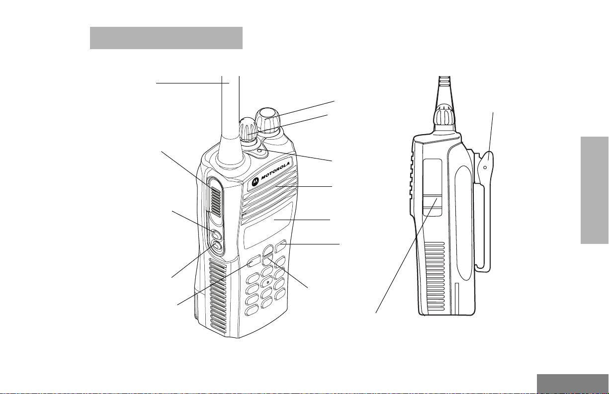
FULL KEYPAD RADIO OVERVIEW
Antenna
Push-to-Talk
(PTT) Button
Side Button 1
(programmable)
Side Button 2
(programmable)
Front Button 1
(programmable)
ON/OFF/Volume
Knob
Channel Selector
Knob
LED Indicator
Microphone/
Speaker
Display
Front Button 2
(programmable)
DTMF Keypad
Accessory Connector
with a Dust Cover
Belt
Clip
RADIO OVERVIEW
3
English
Page 12
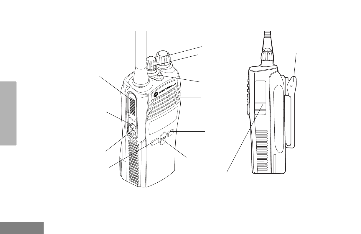
LIMITED KEYPAD RADIO OVERVIEW
RADIO OVERVIEW
Antenna
Push-to-Talk
(PTT) Button
Side Button 1
(programmable)
Side Button 2
(programmable)
Front Button 1
(programmable)
ON/OFF/Volume
Knob
Channel Selector
Knob
LED Indicator
Microphone/
Speaker
Display
Front Button 2
(programmable)
DTMF Keypad
Accessory Connector
with a Dust Cover
Belt
Clip
English
4
Page 13
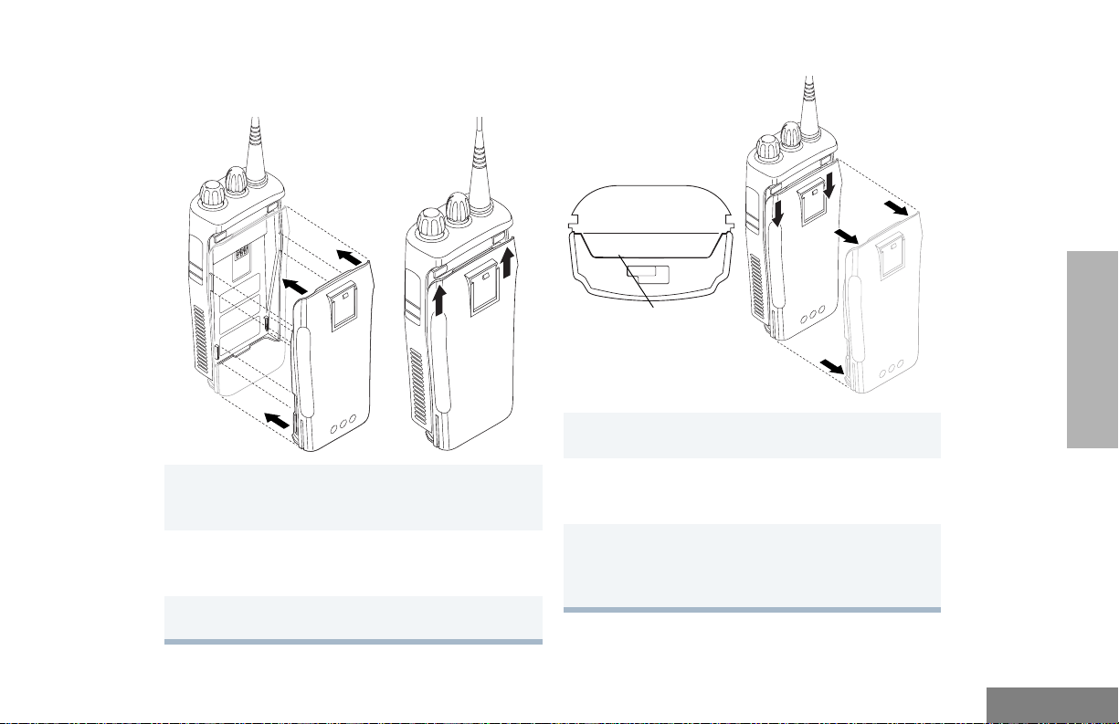
ACCESSORY INFORMATION
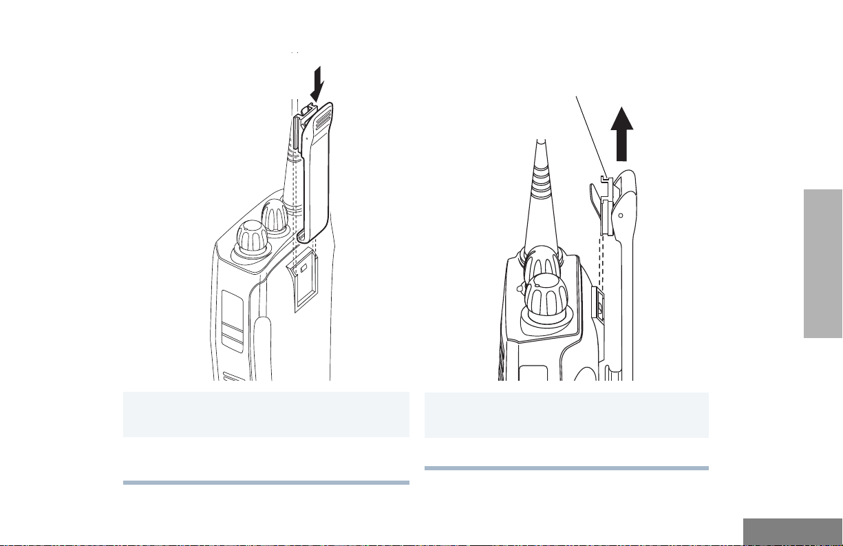
Attach the Battery
Remove the Battery
1 Align the battery to the battery rails on the
back of the radio (approximately 1/2 inch from
the top of the radio.)
2 Press the battery firmly to the radio and slide
the battery upward until the latch snaps into
place.
3 Slide the battery latch, located on radio
bottom, into the lock position.
Locked
Unlocked
Battery Latch
1 Turn OFF the radio if it is turned ON (see
page 20).
2 Slide the battery latch into the unlock position.
Disengage by pushing downward and holding
the latch towards the front of the radio.
3 With the battery latch disengaged, slide the
battery down from the top of the radio about
1/2 inch. Once the battery is free from the
battery rails, lift it directly away from the radio.
RADIO OVERVIEW
5
English
Page 14
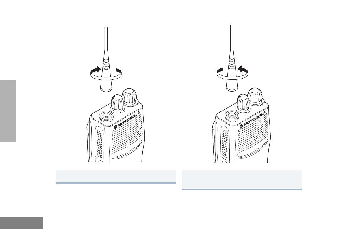
Attach the Antenna Remove the Antenna
RADIO OVERVIEW
Turn the antenna clockwise to attach it. Turn the antenna counterclockwise to remove
it.
English
6
Page 15
Attach the Belt Clip Remove the Belt Clip
Belt Clip Tab
RADIO OVERVIEW
1 Align the grooves of the belt clip with those of
the battery.
2 Press the belt clip downward until you hear a
click.
1 Use a key to press the belt clip tab away from
the battery to unlock the belt clip.
2 Slide the belt clip upward to remove it.
7
English
Page 16

BATTERY INFORMATION
Charging Your Battery
This radio is powered by a nickel-cadmium
(NICd), a nickel-metal hydride (NiMH), or a
lithium-ion (Li-lon) rechargeable battery.
Charge the battery before use to ensure
optimum capacity and performance. The
battery was designed specifically to be used
with a Motorola charger. Charging in nonMotorola equipment may lead to battery
damage and void the battery warranty.
Note: When charging a battery attached to a radio,
The battery should be at about 77°F (25°C)
(room temperature), whenever possible.
RADIO OVERVIEW
Charging a cold battery (below 50° F [10°C])
may result in leakage of electrolyte and
ultimately in failure of the battery. Charging a
hot battery (above 95°F [35°C]) results in
reduced discharge capacity, affecting the
performance of the radio. Motorola rapid-rate
battery chargers contain a temperaturesensing circuit to ensure that batteries are
charged within the temperature limits stated
above.
If a battery is new, or its charge level is very
low, you will need to charge it before you can
use it. When the battery level is low and the
radio is in transmit mode you will see the LED
indicator blink red. Upon release of the PTT
button, you will hear an alert tone.
Note: Batteries are shipped uncharged from the
factory. Always charge a new battery 14 to 16
hours before initial use, regardless of the
status indicated by the charger.
Note: Do not use the wall charger and desktop
charger at the same time when charging.
turn the radio OFF to ensure a full charge.
English
8
Page 17

WALL CHARGER
Note: Do not use the wall charger if using lithium-
ion (Li-Ion) or nickel-metal hydride (NiMH)
batteries. The wall charger is for a nickelcadmium (NiCd) battery only.
To Charge the Battery:
1 Turn the radio OFF.
2 Lift the dust cover to expose the audio
accessory connector.
5 Unplug the charger from the electrical outlet
and radio after 10 hours.
Note: After the initial charge of 14 to 16
hours, do not charge the battery more
than 10 hours.
DESKTOP CHARGERS
Rapid Charger
RADIO OVERVIEW
1 Turn the radio OFF.
3 Insert the charging adapter into the accessory
connector.
4 Plug the charging adapter into an electrical
outlet.
• The LED on the charging adapter lights
red while the charger is plugged into an
electrical outlet.
Note: Do not leave the charger connected to
the radio when it is not connected to
the electrical outlet.
2 Place the battery, with or without the radio, in
the charger pocket.
• The charger LED indicates the charging
progress.
LED color Status
No LED Indication Battery inserted incorrectly
or battery not detected.
Single Green Blink Successful charger
power-up.
Blinking Red
Steady Red Battery is in Rapid charge
a
Battery unchargeable or not
making proper contact.
mode.
9
English
Page 18
RADIO OVERVIEW
LED color Status
Blinking Yellow Battery in charger but
waiting to be charged. The
battery temperature may be
too hot or too cold. The
voltage may be lower than
the predetermined threshold
level for charging.
b
Blinking Green
Green Battery fully charged.
a. Remove the battery from the charger and
use a pencil eraser to clean the three metal
contacts at the back of the battery. Place the
battery back into the charger. If the LED
indicator continues to blink red, replace the
battery.
b. A standard battery may require 90 minutes
to charge to 90% capacity. Even though new
batteries might prematurely indicate a full
charge (steady green LED), charge the
battery for 14 to 16 hours prior to initial use
for best performance.
Battery 90% (or more)
charged. Trickle charging.
A list of Motorola authorized batteries and
battery chargers appears on page 56. The
listed chargers will charge only Motorola
authorized batteries. Other batteries may not
charge.
Slow Charger
Note: Do not use the slow charger if using lithium-
ion (Li-Ion) or nickel-metal hydride (NiMH)
batteries. The slow charger is for a nickelcadmium (NiCd) battery only.
1 Turn the radio OFF.
2 Place the battery, with or without the radio, in
the charger pocket.
• The charger LED indicates the charging
progress.
LED color Status
No LED Indication Battery inserted incorrectly
or battery not detected.
Steady Red Battery is in over night
charge mode. The battery is
fully charged after 11 hours.
English
10
Page 19
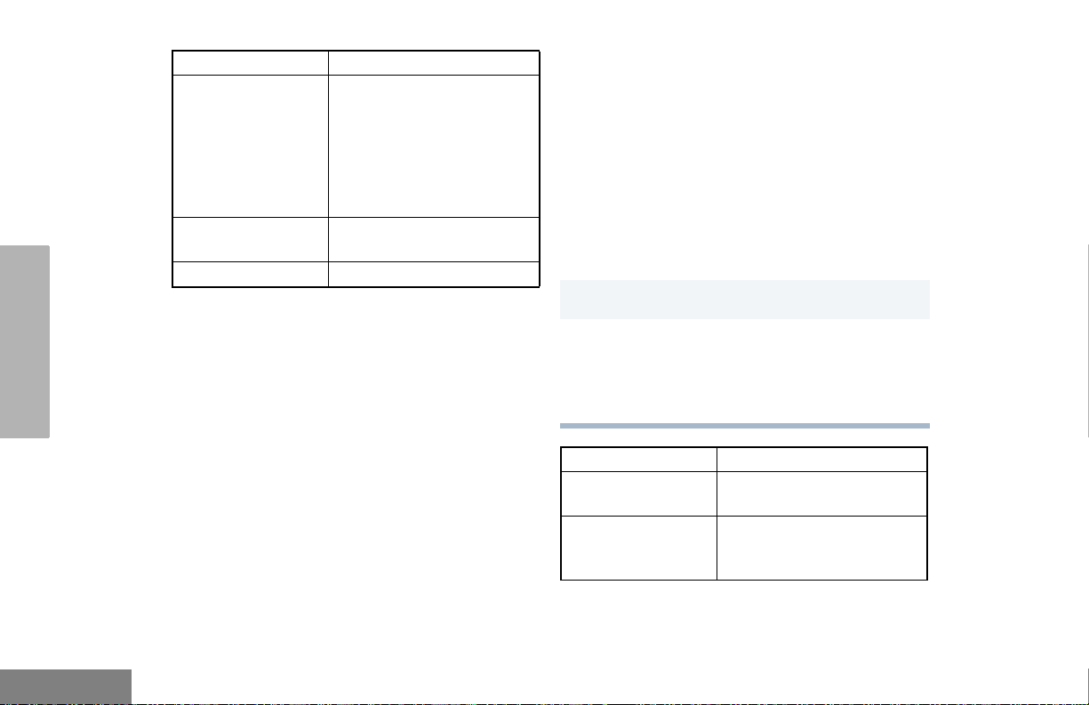
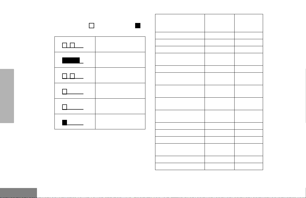
BATTERY CHARGE STATUS
You can check battery charge status if your
dealer has preprogrammed one of the
programmable buttons. Hold down the
preprogrammed Battery Indicator button. The
charge status is shown on the display.
Battery
Level
Full
Good
Fair
Low
Very Low
Display
LED INDICATOR
Indicates power-up, transmit, receive, scan
monitor status, channel/talkgroup busy, Call
Alert™ receive/transmit, Selective Call receive/
transmit, and battery status.
LED State/Color Indication
Radio Call
Red Transmitting
Blinking Red Receiving
Blinking Red Channel/Talkgroup Busy
Scan
Blinking Green Scanning for activity
Call Alert
Blinking Yellow Indicates receiving a Call Alert
Yellow Indicates sending a Call Alert
Selective Call
Blinking Yellow Indicates receiving a Selective
Call
Yellow Indicates sending a Selective
Call
Monitor/Open Squelch
Yellow While monitoring
Low Battery
Blinking Red
when transmitting
Low battery level
RADIO OVERVIEW
11
English
Page 20

DISPLAY
The top display row displays menu and radio
status information:
RADIO OVERVIEW
PERS4
Symbol Indication
I
Signal Strength
B
Power Level
C
Monitor
D
Phone
The more bars, the stronger
the signal being received by
your radio.
Low Power “R” or High Power
“S” is activated.
The selected channel is being
monitored.
Phone mode is selected.
Symbol Indication
H
•Priority 1 Scan
(
Blinking)
•
H
Priority 2 Scan
(• Steady)
J
Talkaround
F
Call Received
B
L
Keypad Lock
Indicates scan has stopped
on an active Priority 1
channel/talkgroup.
Indicates scan has stopped
on an active Priority 2
channel/talkgroup.
Bypass the repeater and talk
directly to another radio.
A Selective Call or Call Alert
has been received.
Not Used.
The keypad has been locked.
English
12
G
Scan
Indicates that the Scan
feature has been activated.
Page 21
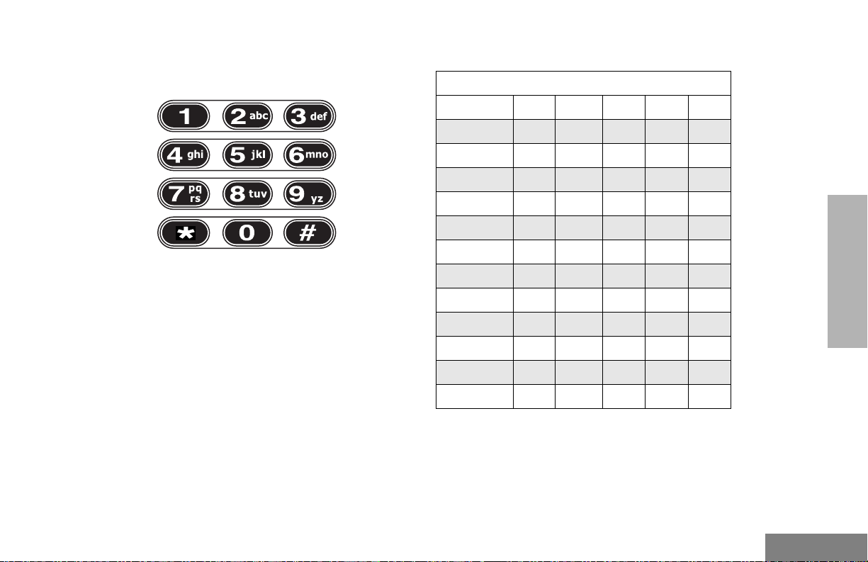
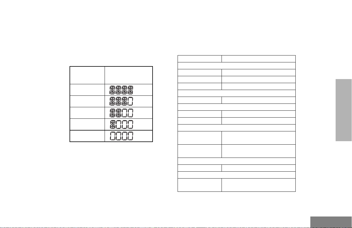
DTMF KEYPAD (FULL KEYPAD MODEL ONLY)
*
The keypad is used for:
• Dialing a phone number.
• Entering information when programming phone
lists.
• Accessing a repeater.
• Each key can generate several different
characters. For example, to enter the character
“C,” press the 2 button three times. (Refer to
the following table.)
Entering Characters Using the
DTMF Keypad
Number of Times Button is Pressed
Button 1 2 3 4 5
0 0
1 1/ \
2 A B C 2
3 DE F 3
4 G H I 4
5 JK L5
6 M N O 6
7 PQ RS7
8 T U V 8
9 WX Y Z 9
* * < >
# #+ - _
RADIO OVERVIEW
13
English
Page 22
INDICATOR TONES
High pitched tone Low pitched tone
RADIO OVERVIEW
Some programmable buttons use tones to
indicate one of two modes:
Self Test Pass Tone
Self Test Fail Tone
Positive Indicator Tone
Negative Indicator
To ne
Good Key Tone
Bad Key Tone
ProgrammableButton
s
Scan Start Stop
Power Level High Low
Squelch Tight Normal
Repeater/Talkaround Does not
VOX Enabled Disabled
Silent Monitor/Open
Squelch
Revert Memory
Channel (1&2)
Store Memory
Channel (1&2)
Home Revert AutoKey
(1&2)
Menu Mode
Radio Call — Enabled
Scan List Edit — Enabled
Speed Dial (Full
Keypad Model Only)
Phone Mode — Enabled
Escalert Enabled Disabled
J — Accessed
Positive
Indicator
Tone
use repeater
— Enabled
— Enabled
—Stored
— Enabled
— Enabled
Negative
Indicator
Tone
Uses
repeater
English
14
Page 23

PROGRAMMABLE BUTTONS
Your radio has four programmable buttons.
Your dealer can program these buttons as
shortcuts to various radio features.
Check with your dealer for a complete list of
functions your radio supports.
Programmable buttons include:
• The two side buttons (S1 and S2)
• The two front buttons (K and J)
Some buttons can access up to two features,
depending on the type of button press:
• Short Press — quickly pressing and releasing
the programmable buttons.
• Long Press — pressing and holding the
programmable buttons for a minimum of 2.5
seconds.
• Hold Down — pressing and holding down the
programmable buttons while checking status or
making adjustments.
The table on page 16 summarizes the
programmable features available and shows
the page number where the feature is
explained.
In the “Button” column, have your dealer
record the name of the programmable button
next to the feature that has been programmed
to it.
The dealer can use the abbreviations (S1, S2,
P1, or P2) shown in the radio illustration on
page 3.
Also, where appropriate, have your dealer
indicate whether the button press requires a
short press, a long press, or needs to be held
down.
RADIO OVERVIEW
15
English
Page 24
Battery
Indicator
Menu Mode — J button enters Menu Mode and
Volume Set — — — Sounds a tone
Monitor C A long press initiates Monitor. A short
RADIO OVERVIEW
Repeater/Talkaround J Toggles between using a repeater or
Revert Memory
Channel (1&2)
†
This function is activated by EITHER a short OR a long press, but not both.
Programmable Features
Feature Indicator Short Press Long Press Hold Down Page Button
— — Checks the
selects menu options. Once in Menu
K button is automatically
Mode,
re-assigned to exit Menu Mode.
press cancels Monitor.
transmitting directly to another radio.
— Allows instant
access to the
home channel/
talkgroup.
battery charge
status.
—19
†
for adjusting the
radio’s volume
level.
Monitors the
selected
channel for any
activity.
—24
†
——25
11
J
21
22
English
16
Page 25

Programmable Features (Continued)
Feature Indicator Short Press Long Press Hold Down Page Button
Store Memory
Channel (1&2)
Home Revert AutoKey
(1&2)
Voice Operated
Transmission (VOX)
Keypad Lock/Unlock L Toggle keypad
Radio Call — Directly access radio call menu.
Scan/Nuisance
Channel/Talkgroup
Delete
Edit Scan List — Add, delete, or prioritize channels/
†
This function is activated by EITHER a short OR a long press, but not both.
— Stores current
channel/talkgroup
to the home
channel/talkgroup.
— If a Revert Memory Channel is an LTR
talkgroup, the radio keys-up and
transmits an MDC PTT ID. If a Revert
Memory Channel is a conventional
channel, it does not key-up.
— Toggle VOX ON and OFF.
†
†
between locked
and unlocked.
†
G Starts or stops the
Scan operation.
Deletes a nuisance
channel/talkgroup
while scanning.
talkgroups.
†
—25
—26
RADIO OVERVIEW
—26
27
— 29,30
— 32,33
—35
17
English
Page 26
Phone D Directly access phone mode.
Speed Dial (Full
Keypad Model Only)
Escalert — Toggle escalert ON and OFF.
Squelch — Toggle squelch level between tight and
Power Level
Lights — Toggle keypad and display backlights
†
This function is activated by EITHER a short OR a long press, but not both.
RADIO OVERVIEW
Programmable Features (Continued)
Feature Indicator Short Press Long Press Hold Down Page Button
†
D Quickly access speed dial phone list.
†
†
†
†
B
normal squelch.
Toggle transmit power level between
High and Low power.
ON and OFF.
†
— 38,39
—40
—47
—50
—50
—51
English
18
Page 27

MENU BUTTONS
Menu Button
If preprogrammed by your dealer, the two front
buttons (
conjunction with other programmable features,
to access and select menu options (
exit menu mode (
The
dealer to either a short or long press to access
the Menu Mode.
Menu Scroll Buttons
Navigate the Menu
K and J) can be used, in
J); and
K).
J button can be preprogrammed by your
Used to scroll while in Menu Mode.
Refer to the menu navigation chart for
menu selectable features at the back of
this manual.
L or M to scroll through the menu
options. If you scroll past the last option, the
selection wraps around and starts again.
When you reach the required option, a short
press of the
enters the sub-menu.
J button selects that option and
L or M to scroll through the sub-menu
options. Select the option with a short press of
the
J button.
Exit the Menu
While in Menu Mode, the
automatically assigned to completely exit the
Menu Mode by a long press, or by a series of
short presses to exit from a sub-level of the
menu hierarchy.
The radio also exits the menu mode if there
have been no inputs via the navigation buttons
for the default “Inactivity Time” or after a
selection has been made.
Once you have exited Menu Mode, the
K button is
K and
J buttons return to normal programmable
condition.
RADIO OVERVIEW
19
English
Page 28

GETTING STARTED
ON OFF
TURN THE RADIO ON OR OFF
Rotate the ON/OFF/
Volume knob
clockwise. If power-up
is successful, you will
hear the Self-Test
Pass Tone
( ) and see
the display icons light
momentarily and the
LED blink green.
If the radio fails to
power up, you will
hear the Self Test Fail
Tone ( ).
The radio will need to
be returned for
reprogramming.
Rotate the ON/OFF/
Vol ume knob
counterclockwise until you
hear a click and both the
display and LED indicator
turn OFF.
GETTING STARTED
English
20
Page 29

ADJUST THE VOLUME
To select an LTR Channel/Talkgroup:
Turn the ON/OFF/Volume Control knob
clockwise to increase the volume, or
counterclockwise to decrease the volume.
–or–
Note: Your dealer can preprogram one of the
programmable buttons to Volume Set.
1 Hold down the Volume Set button (see
page 16).
• You will hear a continuous tone.
2 Turn the ON/OFF/Volume knob to the desired
volume level.
3 Release the Volum e S e t button.
SELECT AN LTR CHANNEL/ TALKGROUP
Your CP200XLS display radio can be
programmed with up to 10 LTR sites and a
maximum of 100 talkgroups, in total, across
one or more sites (up to a total of 10 sites).
Turn the Channel Selector knob to select
1
the appropriate LTR channel/talkgroup.
–or–
L or M to select the appropriate LTR
channel/talkgroup.
–or–
Press any of the programmable buttons to
access a preprogrammed talkgroup. Then
use either the Channel Selector knob or
L and M to select the appropriate LTR
channel/talkgroup.
Note: The third option is available only if
your radio has been programmed
with a specified LTR channel/
talkgroup.
Note: Site/talkgroup settings are programmed
by your dealer.
GETTING STARTED
21
English
Page 30

SELECT A CONVENTIONAL RADIO CHANNEL
Your radio offers 128 conventional channels.
To select a channel, turn the Channel
Selector knob clockwise or counterclockwise
until you reach the desired channel.
RECEIVE A CONVENTIONAL OR LTR CALL
1 Turn your radio on.
2 Adjust the radio’s volume (see page 21).
3 Turn the Channel Selector knob to select the
desired conventional channel or LTR
talkgroup,
–or–
L or M to select the desired
conventional channel or LTR talkgroup.
• Make sure the PTT button is released.
4 Listen for voice activity.
• The LED indicator blinks red while your
radio is receiving.
5 To respond, hold the radio vertically 1 to 2
inches (2.5 to 5cm) from your mouth. Press
the PTT button to talk; release it to listen.
MONITOR
It is important to monitor for traffic before
transmitting to ensure that you do not “talk
over” someone who is already transmitting.
1 Press and hold the preprogrammed Monitor
button to access channel traffic.
• If no activity is present, you will hear “white
noise.”
2 Once channel traffic has cleared, proceed
with your call by pressing the PTT button.
GETTING STARTED
English
22
Page 31

Permanent Monitor
1 A long press of the preprogrammed Monitor
button places the radio in Permanent Monitor
mode.
• You hear a good key tone.
2 A short press of the Monitor button cancels
Permanent Monitor mode and returns the
radio to normal operation.
TRANSMIT AN LTR CALL
Turn the Channel Selector knob to select the
1
appropriate LTR channel/talkgroup.
–or–
L or M to select the appropriate LTR
channel/talkgroup.
Hold the microphone in a vertical position at a
2
distance of about 1 to 2 inches
(2.5 to 5 cm) from your mouth.
Press and hold the PTT button.
3
–or–
Press and release the PTT button and wait 3
seconds.
• If access to the trunked system was
successful, the red LED indicator lights
steady.
• If access to the trunked system was
unsuccessful, the red LED indicator blinks,
indicating that the system was busy or outof-range.
With the PTT button depressed, speak clearly
4
into the microphone.
Release the PTT button to listen.
5
GETTING STARTED
23
English
Page 32

TRANSMIT A CONVENTIONAL CALL
1 Turn your radio on.
2 Use the Channel Selector knob to select the
desired channel.
Note: Monitor for traffic before transmitting to
ensure that you do not “talk over”
someone who is already transmitting
3 Hold the radio vertically 1 to 2 inches (2.5 to
5cm) from your mouth. Press the PTT button
to talk.
• The LED indicator lights steady red while
the call is being sent.
CALL LIGHT
(TRUNKED OPERATION ONLY)
The Call Light indicator informs you that you
have received a call from a specified LTR
talkgroup (as programmed by your dealer).
The yellow LED indicator will blink
continuously, indicating that a call has been
received.
To turn the call light OFF:
• turn the radio OFF, then ON again, or
• change the channel/talkgroup, or
• press the PTT button, or
• press any valid button.
®
GETTING STARTED
English
4 Release the PTT to listen.
24
REPEATER OR TALKAROUND J MODE
Talkaround Mode enables you to communicate
with another radio when either:
• The repeater is not operating.
–or–
• Your radio is out of the repeater’s range but
within communicating distance of another radio.
Page 33

Note: The J symbol appears on the display when
Talkaround Mode is selected.
To Select either Repeater Mode or
Talkaround Mode
Press the preprogrammed Repeater/
Talkaround button (see page 16) to toggle
between Repeater Mode and Talkaround Mode.
– or –
REVERT MEMORY CHANNEL (1 & 2)
The Revert Memory Channel feature allows
you to instantly access up to two of your
favorite channels/talkgroups at the touch of a
button.
Press the preprogrammed Revert Memory
Channel 1 button or Revert Memory Channel
2 button (see page 16).
J to enter menu mode.
1
L or M until
2
J to select the current setting.
3
L or M until
4
-or- until
J to select the current setting.
5
TALKARND
TALKARND
REPEATER
STORE MEMORY CHANNEL (1 & 2)
The Store Memory Channel (1 & 2) feature
allows you to store a channel/talkgroup for the
Revert Memory Channel feature.
Use the Channel Selector knob to select the
desired channel/talkgroup. Press the
preprogrammed Store Memory Channel 1
button or Store Memory Channel 2 button to
store that channel/talkgroup (see page 16).
25
GETTING STARTED
English
Page 34

HOME REVERT AUTOKEY (1 & 2)
If a Revert Memory Channel is an LTR
talkgroup, the Home Revert AutoKey feature
automatically keys-up and transmits an MDC
PTT ID. If a Revert Memory Channel is
programmed as a Conventional channel, the
radio will not key-up (see page 17).
VOX OPERATION
When hands-free operation is desired, your
radio can transmit by voice alone using the
VOX feature when you speak through an
accessory that is connected to your radio.
Connecting a VOX Headset
You can select channels/talkgroups to enable
or disable VOX as preprogrammed by your
dealer/programmer.
1 Select a channel/talkgroup that has been
preprogrammed by your dealer to enable
VOX.
Note: Pressing the PTT button disables
VOX.
2 Select a channel/talkgroup that has not been
preprogrammed by your dealer to disable
VOX.
ENABLE/DISABLE HEADSET SIDETONE
GETTING STARTED
English
1 Turn OFF your radio.
2 Connect the VOX accessory to your radio and
turn the radio ON.
Enable or Disable VOX
To enable or disable VOX operation, press the
preprogrammed VOX button (see page 17).
Note: Pressing the PTT button disables VOX.
– or –
26
Your dealer can program your radio so you can
hear your voice through a headset while you
speak.
VOX Headset
1 To enable the headset sidetone, turn OFF
your radio.
2 Connect the VOX headset accessory to your
radio.
Page 35

3 Turn the radio ON. During transmit, you will
hear your voice through the headset while
you speak.
4 To disable the headset sidetone, turn OFF
your radio and turn the radio ON again.
Non-VOX Headset with In-Line PTT
1 To enable the headset sidetone, turn OFF
your radio.
2 Connect the non-VOX accessory to your
radio.
KEYPAD LOCK/UNLOCK L
To lock or unlock the keypad, long press the
preprogrammed Keypad Lock/Unlock button
(see page 17).
Note: The L symbol appears on the display when
the keypad is locked.
PROGRAM PL/DPL CODES
Use this feature to edit the Private-Line/Digital
Private-Line codes for a selected channel/
talkgroup.
J to enter menu mode.
1
3 Press and hold the In-line PTT on your
headset.
4 Turn the radio ON and release the PTT once
the radio has completed start-up. During
transmit, you will hear your voice through the
headset while you speak.
5 To disable the headset sidetone, turn OFF
your radio and turn the radio ON again.
L or M until
2
J to select
3
L or M until
4
- or - until
J to select the current setting.
5
EDIT PL
EDIT PL
RX XXX.X
TX XXX.X
GETTING STARTED
27
English
Page 36

L or M to scroll through the standard
6
TPL frequencies or DPL codes.
- or -
Enter a non-standard or standard 4-digit TPL
frequency or the 3-digit octal (numbers 0 –7
only) code for DPL via the DTMF microphone
keypad (Full Keypad Model only).
J to confirm selection.
7
K until you exit menu mode.
8
GETTING STARTED
English
28
Page 37

RADIO CALLS
SELECTIVE RADIO INHIBIT
• The LED indicator blinks yellow, if programmed
by your dealer/programmer.
• You hear two high-pitched tones.
RADIO CALLS
Your radio is equipped with a security feature
that can temporarily render the unit inoperative
when an inhibit signal is sent from the base
station.
This feature is commonly used to disable
radios:
• In case of theft
• For system control reasons
When your radio has been rendered
inoperative by the base station, all controls will
be inoperative except for the ON/OFF button
and the display shows INHIBIT.
RECEIVE A SELECTIVE CALL F
(CONVENTIONAL OPERATION ONLY)
When you receive a selective call:
• The display shows F and the preprogrammed
name or ID (MDC1200) of the calling radio, or
you will hear a Call Alert tone (QCII) of the
calling radio.
1 To acknowledge the call, press and release the
PTT button.
2 Press and hold the PTT button to talk; release
to listen.
SEND A SELECTIVE CALL
(CONVENTIONAL OPERATION ONLY)
You can send a Selective Call to a particular
radio or to a group of radios, as programmed
by your dealer.
Press the preprogrammed Radio Call button
(see page 17), and proceed to step 4.
–
or –
29
English
Page 38

RADIO CALLS
1 J to enter menu mode
2 L or M until
3 J to select
4 L or M until
5 J to select
6 L or M to locate the desired ID in the
Radio Call List.
- or Enter a valid DTMF digit (0 – 9) to move to that
location in the list (Full Keypad Model only).
7 Press the PTT button to send the call.
8 Press and hold the PTT button to talk; release
to listen.
9 When the call is completed,
RAD CALL
RAD CALL
SEL CALL
SEL CALL
K until you exit menu mode.
RECEIVE A CALL ALERT™ PAGE F
(CONVENTIONAL OPERATION ONLY)
When you receive a Call Alert page:
• The display shows F and the preprogrammed
name or ID of the calling radio.
• The LED indicator blinks yellow, if programmed
by your dealer/programmer.
• You hear four high-pitched tones.
To acknowledge the page, press and release
the PTT button; to cancel the page, press any
other key.
SEND A CALL ALERT PAGE
(CONVENTIONAL OPERATION ONLY)
You can alert another person by sending a Call
Alert page.
Press the preprogrammed Radio Call button
(see page 17) and proceed to step 4.
–
or –
English
30
Page 39

1 J to enter menu mode
2 L or M until
3 J to select
4 L or M until
RAD CALL
RAD CALL
CALL ALT
REPEATER ACCESS (FULL KEYPAD MODEL ONLY)
Use this feature to send DTMF tones to a
repeater.
1 Press and hold the PTT button and enter your
access code using the DTMF keypad.
RADIO CALLS
5 J to select
6 L or M to locate the desired ID in the
Radio Call List.
- or Enter a valid DTMF digit (0 – 9) to move to that
location in the list (Full Keypad Model only).
7 Press the PTT button to send the page.
8 When the page is completed,
CALL ALT
K until you exit menu mode.
2 Press and release the required DTMF buttons.
3 Release the PTT button.
RADIO CHECK (FULL KEYPAD MODEL ONLY)
Radio Check allows you to determine if a radio
is within the range of the trunked system and
turned ON, without disturbing the user of that
radio. This feature can also be used when
attempts with Selective Call and Call Alert fail.
31
English
Page 40

SCAN
SCAN
Your radio is equipped with the Scan feature,
which allows you to monitor multiple channels/
talkgroups for voice activity. The radio will stop
on a channel/talkgroup when it detects activity
on it.
Scan lists are assigned per channel/talkgroup,
by your dealer/programmer. Your radio
automatically switches to a channel/talkgroup,
within that scan list, when it detects activity.
You can edit these lists through your radio’s
menu (see page 35).
• The LED indicator blinks green during scan
mode; it stops blinking when the radio switches
to an active channel/talkgroup.
•The Gsymbol appears on the display while in
scan mode.
There are two ways that your radio scans:
• System Scan (manual)
• Auto Scan (automatic)
TALKBACK
The Talkback feature allows you to respond to
a transmission while scanning. If transmission
is detected on a channel/talkgroup while
scanning, the radio will stop on that channel/
talkgroup for a default period of time after
activity has ceased. This is referred to as
“hangtime”. During this hangtime you may
respond by pressing the PTT button.
Note: The LED scan indicator stops blinking while
the radio is in hangtime. If the PTT button is
not pressed after the preprogrammed
hangtime, the radio returns to scanning
channels/talkgroups.
START SYSTEM SCAN G
Press the preprogrammed Scan button to start
scanning channels/talkgroups in your scan list
(if Auto Scan is not enabled) (see page 17).
– or –
1 Select a channel or talkgroup that contains a
Scan list.
English
32
J to enter menu mode.
2
Page 41

3 L or M until
SYS SCAN
4 L or M until
SCAN OFF
4 J to select
The display shows the current scan status.
5 L or M until
6 J to select the current setting.
SYS SCAN
SCAN ON
STOP SYSTEM SCAN
Press the preprogrammed Scan button to stop
System Scan (see page 17).
– or –
1 J to enter menu mode.
L or M until
2
3 J to select
The display shows the current scan status.
SYS SCAN
SYS SCAN
5 J to select the current setting.
•The Gsymbol disappears from the dis-
play.
Note: Your dealer/programmer can preprogram
your radio when exiting System Scan to
automatically revert to the last scan channel/
talkgroup that had activity on it or to
automatically revert to the channel/talkgroup
where scan was initiated.
START AUTO SCAN G
Auto Scan automatically starts scanning once
a channel/talkgroup with Auto Scan enabled is
selected.
Select a channel/talkgroup that has been
preprogrammed for Auto Scan by your dealer/
programmer.
STOP AUTO SCAN
Select a channel/talkgroup that has not been
preprogrammed for Auto Scan by your dealer/
programmer.
• The Gsymbol disappears from the display.
SCAN
33
English
Page 42

DELETE A NUISANCE CHANNEL/ TALKGROUP
Restore Channels/Talkgroups to the Scan List
SCAN
Note: Your dealer/programmer must preprogram a
button to access this feature (see page 17).
If a channel or talkgroup continually generates
unwanted calls or noise (a “nuisance” channel/
talkgroup), you can temporarily remove it from
the scan list:
1 While the radio is on the nuisance channel/
talkgroup, press the preprogrammed
Nuisance Channel Delete button until you
hear a tone.
2 Release the Nuisance Channel Delete
button. The nuisance channel/talkgroup is
deleted.
Note: You cannot temporarily delete the
channel/talkgroup that has been
preprogrammed by your dealer/
programmer as your designated scan
channel/talkgroup, a priority channel/
talkgroup, or the last remaining
channel/talkgroup in the scan list.
1 Power OFF the radio. Once the radio is
powered on again, the deleted nuisance
channels/talkgroups are restored to the scan
list.
or –
–
Press the preprogrammed Scan button to stop
the scan.
2 Press the preprogrammed Scan button again
to start scanning again. The deleted nuisance
channels/talkgroups are restored to the scan
list.
or –
–
Select a channel/talkgroup that has not been
preprogrammed for scan by your dealer/
programmer to stop Scan. Once you return to
the original channel/talkgroup, the deleted
nuisance channels/talkgroups are restored to
the scan list.
English
34
Page 43

EDIT A SCAN LIST
Your radio can support up to 16 Scan lists.
Each Scan list can contain up to 16 channels/
talkgroups. The same channel/talkgroup can
be included in several Scan lists, and the same
Scan list can be assigned to several channels/
talkgroups. Scan lists are assigned per
channel/talkgroup, by your dealer/programmer.
When you edit a Scan list, you can either add,
delete, or prioritize channels/talkgroups.
Note: Your radio cannot receive calls while you are
editing a Scan list.
ADD OR DELETE CHANNELS/ TALKGROUPS IN A SCAN LIST
1 Select a channel/talkgroup that contains a
Scan list you want to edit.
J to enter menu mode.
2
3 L or M until
PROG LST
Note: One Scan list per channel/talkgroup is
available.
J to select
6
7 L or M until
– or – until
8 J to select the current setting.
9 L or M until you see the channel/
talkgroup
J to confirm your selection.
10
11 If you added a channel/talkgroup,
you see:
– or –
If you delete a channel/talkgroup,
you see:
you want to add or delete.
SCAN LST
ADD ITEM
DELETE
ADDED
DELETE
SCAN
4 J to select
5 L or M until
PROG LST
SCAN LST
12 J to confirm the deletion.
you see:
DELETED
35
English
Page 44

13 K to return to
– or –
ADD ITEM
DELETE
Priority
Channel/
Talkgroup
Scanning Sequence
SCAN
English
14 K until you exit menu mode.
PRIORITIZE A CHANNEL OR TALKGROUP IN A SCAN LIST
You may want to check the activity on one or
two channels/talkgroups more frequently than
others. You can do this by prioritizing them:
36
None
specified
Channel/
Talkgroup 2
(Priority 1)
Channel/
Talkgroup 2
(Priority 1) and
Channel/
Talkgroup 8
(Priority 2)
Note: If you are receiving on a non-priority
channel/talkgroup and traffic becomes
active on a priority channel/talkgroup, your
radio will automatically switch to that priority
channel/talkgroup and indicate the activity
with a short tone.
Ch1-->Ch2-->Ch3-->
Ch4-->...Ch1
Ch2-->Ch1-->Ch2 -->Ch3--> Ch2
-->Ch4-->Ch2-->...Ch1
Ch2-->Ch1-->Ch8-->Ch3
-->Ch2--->Ch4--->
Ch8--->...Ch1
Page 45

Set Priority Channels/Talkgroups
Note: You cannot assign the same priority to two
different channels/talkgroups.
1 J to enter menu mode.
L or M until
2
PROG LST
10 L or M until you see the channel/
talkgroup you want to prioritize.
– or – until
to select the current
channel/talkgroup the
radio is ON
SELECTED
3 J to select
4 L or M until
5 J to select
6 L or M until
7 J to select
8 L or M until
– or – until
9 J to select the desired priority level.
You see the current priority channel/talkgroup.
PROG LST
SCAN LST
SCAN LST
EDIT PRI
EDIT PRI
PRI #1
PRI #2
– or – until
to de-prioritize the
current channel/
talkgroup the radio is
ON.
11 J to prioritize that channel/talkgroup.
you see:
12 K to return to
13 K until you exit menu mode.
DISABLED
SAVED
EDIT PRI
SCAN
37
English
Page 46

PHONE
PHONE
Your radio allows you to place and receive
telephone calls through a repeater (depending
on phone line availability). You can edit the
phone list through your radio’s menu (see
page 40).
The phone feature is available in both
conventional and LTR systems.
• D appears on the display when you are in
Phone mode.
ACCESS THE REPEATER
Your dealer/programmer can preprogram your
radio in one of three ways to enter your
access/deaccess code to the repeater.
Immediate Auto – your radio will transmit the
access/deaccess code automatically upon
entering phone mode or disconnecting a
phone call. You will hear a series of tones, and
see your access/deaccess code on the display,
indicating that an access/deaccess code is
being sent automatically.
Delayed Auto – your radio will transmit the
access code upon a PTT button press. The
deaccess code is sent automatically when you
exit phone mode.
Manual – Enter your access/deaccess code
using the DTMF keypad (Full Keypad Model
only).
RECEIVE A PHONE CALL D
When a phone call is received, a ringing tone
sounds, alerting you to answer the phone call.
Press the preprogrammed Phone button (see
page 18), and skip to step 6.
– or –
1 Select a channel/talkgroup that has been
programmed for telephone.
J to enter menu mode.
2
3 L or Muntil
4 J to select
Note: The D appears on the display.
PHONE
PHONE
English
38
Page 47

5 Enter your repeater access code, if necessary
(Full Keypad Model only) (see page 38).
6 Press and hold the PTT button to talk. Hold
the radio in a vertical position with the
microphone 1 to 2 inches (2.5 cm to 5 cm)
away from your mouth. Release the PTT
button when the other party wants to talk, both
parties will need to speak in turn.
1 To disconnect a phone call, do one of the
following:
If your radio has Immediate Auto or Delayed
Auto programmed, go to step 2.
– or –
Enter the deaccess code using the DTMF
keypad and press the PTT button (Full
Keypad Model only)
.
7 Disconnect the phone call when the
conversation is completed.
DISCONNECT A PHONE CALL
MAKE A PHONE CALL D
Note: Only the first 8 digits of the phone number will
be displayed on your radio's display.
Press the preprogrammed Phone button (see
page 14), and skip to step 6.
– or –
1 Select a channel/talkgroup that has been
programmed for telephone.
J to enter menu mode.
2
3 L or M until
PHONE
2 To exit Phone Mode:
Press the preprogrammed Phone button (see
page 18).
– or –
Press and hold K to disconnect the call.
Note: D disappears from the display.
J to select
4
5 Enter your repeater access code, if necessary
(Full Keypad Model only) (see page 38).
PHONE
39
PHONE
English
Page 48

PHONE
6 When you hear a dial tone:
Enter the phone
number using the
DTMF keypad (Full
Keypad Model Only).
– or –
L or M to
select a number from
the phone list.
– or –
a. Press and release the preprogrammed
Speed Dial button.
b. Press the key (0 to 9) corresponding to
the number you want to call (Full Keypad
Model Only).
Note: To redial the last number dialed (if not
using Speed Dial), press and release
the PTT button immediately after the
access code is sent. The radio sends
the last number dialed.
XXXXXXX
XXXXXXXX
7 – or –
If you entered your access code
using the DTMF keypad, press
once to access the last number
dialed; then press and release the
PTT button.
8 Press and release the PTT button, if required
for your radio.
9 When your party answers, press and hold the
PTT button to talk. Hold the radio in a vertical
position with the microphone 1 to 2 inches
(2.5 to 5 cm) away from your mouth. Release
the PTT button when the other party wants to
talk, both parties will need to speak in turn.
10 Disconnect the phone call when the
conversation is completed (see page 39).
L
EDIT THE PHONE LIST (FULL KEYPAD MODEL ONLY)
Your radio contains a Phone list that holds up
to 25 phone numbers. You can edit the Phone
list in three ways through your radio’s menu:
• Add an entry
English
40
Page 49

• Delete an entry
• Edit an existing entry
Add an Entry
10 Use the DTMF keypad to enter the phone
number. You can also add a Pause Indicator by
holding # until ‘P’ appears on the display.
1 J to enter menu mode.
2 L or M until
3 J to select
4 L or M until
5 J to select
6 L or M until
7 J to select,
you see:
8 Use the DTMF keypad to enter the name (see
Entering Characters Using the DTMF Keypad
on page 13.)
9 J to store the name,
you see:
PROG LST
PROG LST
PHN LST
PHN LST
ADD ITEM
ADD ITEM
NAME
NUMBER
11 J to store the phone number.
you see:
12 L or M until you see the location in the
list where you want to store the phone number.
13 J to store the phone number,
you see:
14 K to return to
– or –
LOC XX
SAVED
ADD ITEM
K until you exit menu mode.
Delete an Entry
1 J to enter menu mode.
2 L or M until
3 J to select
PROG LST
PROG LST
PHONE
41
English
Page 50

4 L or M until
PHN LST
3 J to select
PROG LST
PHONE
5 J to select
6 L or M until
7 J to select
8 L or M until you see the entry you want
to delete.
9 J to select the entry,
you see:
10 J again to confirm the deletion,
you see:
11 K to return to
– or –
PHN LST
DELETE
DELETE
DELETE
DELETED
DELETE
K until you exit menu mode.
Edit an Entry
1 J to enter menu mode.
2 L or M until
PROG LST
4 L or M until
5 J to select
6 L or M until
7 J to select
8 L or M until you see the entry you want
to edit.
9 J to select the entry.
10 L or M u n t i l
(to edit the name),
– or – until
(to edit the phone
number),
– or – until
(to edit the location in
the phone list).
11 J to confirm your selection.
PHN LST
PHN LST
EDIT
EDIT
NAME
NUMBER
LOC
English
42
Page 51

Use the DTMF keypad to edit the entry (see
12
Entering Characters Using the DTMF Keypad
on page 13.)
– or –
L or M until you see the location where
you want to store the phone number.
13 J to store the information.
14 you see:
15 K to return to
– or –
SAVED
EDIT
4 L or M until
5 J to select
6 L or M until
7 J to select
8 L or M until
– or – until
9 J to select the current setting.
PHN LST
PHN LST
EDT CODE
EDT CODE
ACCESS
DEACCESS
K until you exit menu mode.
Edit Access/Deaccess Codes
You can edit the access/deaccess codes that
are used to connect or disconnect you from a
repeater.
1 J to enter menu mode.
2 L or M until
3 J to select
PROG LST
PROG LST
10 Enter the number using the DTMF keypad.
11 J to select the entry.
12 you see:
13 L or M to edit another code.
14 K until you exit menu mode.
SAVED
PHONE
43
English
Page 52

TONE PREFERENCES
You can use the radio’s menu to access useradjustable settings to customize the tones on
your radio.
1 J to enter menu mode.
TONE PREFERENCES
English
2 L or M until
3 J to select
4 L or M until you see the feature you
want to change (see the table on page 45).
5 J to select the feature. You see the feature’s
current setting.
6 L or M to see a list of available
settings.
7 J to select the desired setting.
K until you exit the menu mode.
8
44
TONES
TONES
Page 53

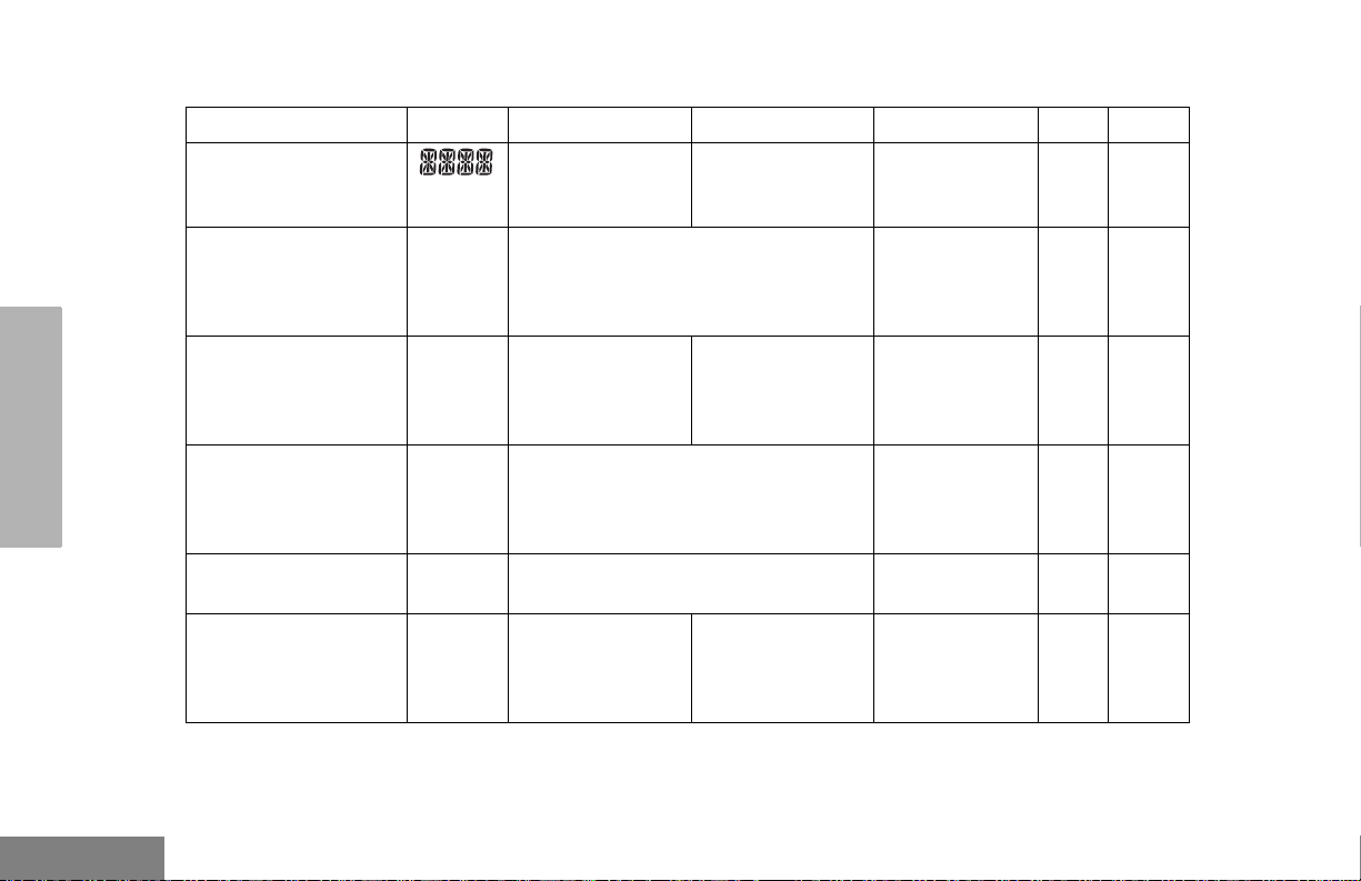
Tone Settings
Feature What it Does Settings
TONE PREFERENCES
TONE
KPD TONE
TONE TAG
ESCALERT
Turns all alert tones ON or OFF.
Turns the keypad tones ON or OFF.
Assigns a specific tone when receiving a specific type of
radio call.
Increases the volume of the alarm tones when a radio call
is not answered.
ON
OFF
ON
OFF
STANDARD
ALERT 1 – 6
ON
OFF
45
English
Page 54

TONE PREFERENCES
TONES ON/OFF
You can program your radio to enable or
disable all alert tones.
1 J to enter Menu mode.
2 L or M until
3 J to select
4 L or M until
5 J to select
6 L or M until
– or – until
7 J to select the desired setting.
TONES
TONES
TONE
TONE
ON
OFF
Note: Tones for the programmable buttons K, J,
and Side Buttons 1 and 2 can not be
disabled.
1 J to enter Menu mode.
2 L or M until
3 J to select
4 L or M until
5 J to select
6 L or M until
– or – until
7 J to select the desired setting.
TONES
TONES
KPD TONE
KPD TONE
ON
OFF
English
KEYPAD ON/OFF TONES
You can program your radio to enable or
disable all keypad tones.
46
CALL TONE TAGGING
(CONVENTIONAL OPERATION ONLY)
You can program your radio to sound a
particular alert tone when receiving Selective
Call or Call Alert (call tone tagging).
Page 55

Note: Seven alert tones are available to select from
in the list.
ESCALERT
(CONVENTIONAL OPERATION ONLY)
TONE PREFERENCES
1 J to enter menu mode.
2 L or M until
3 J to select
4 L or M until
5 J to select
6 L or M until
– or – until
7 J to select the desired setting.
8 L or M until you see and hear the tone
you want to use for this type of call.
9 J to select the desired setting.
10 you see:
11 K to return to
12 K until you exit the menu mode.
TONES
TONES
TONE TAG
TONE TAG
CALL ALT
SEL CALL
TONE SET
TONE TAG
You can program your radio to increase the
volume of the alarm tones when a radio call is
not answered.
Press the preprogrammed Escalert button
(see page 18) and proceed to step 5.
– or –
1 J to enter menu mode.
2 L or M until
3 J to select
4 L or M until
5 J to select
6 L or M until
or until
7 J to select the desired setting.
TONES
TONES
ESCALERT
ESCALERT
ON
OFF
47
English
Page 56

USER SETTINGS
You can use the radio’s menu to access useradjustable settings to customize some of your
radio features.
1 J to enter menu mode.
USER SETTINGS
English
2 L or M until
3 J to select
4 L or M until you see the feature you
want to change (see table on page 49).
5 J to select the feature. You see the feature’s
current setting.
6 L or M for available settings.
7 J to select the desired setting.
48
UTILITY
UTILITY
Page 57

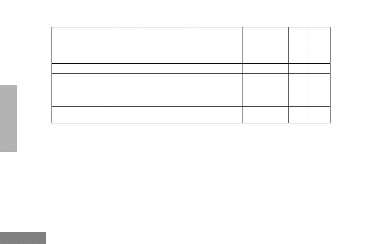
Utilities Features
Feature What it Does Settings
SQUELCH
PWR LVL
OPT BRD
LIGHT
SOFTWARE
Changes the squelch of the radio to tight or normal.
Changes the power level of the radio to high or low.
Enables or disables an option board.
Enables or disables the radio’s keypad and display
backlight.
Displays the radio’s software version number.
TIGHT
NORMAL
HIGH
LOW
ON
OFF
ON
OFF
XX’XX’XX
USER SETTINGS
49
English
Page 58

SET SQUELCH LEVEL
SET POWER LEVEL B
USER SETTINGS
Use this feature to filter out (unwanted) calls
and/or background noise. However, tightening
squelch could cause calls from remote
locations to be filtered out as well. In this case,
normal squelch may be more desirable.
Press the preprogrammed Squelch button
(see page 18) to toggle between tight and
normal squelch.
– or –
1 J to enter menu mode.
2 L or M until
3 J to select
4 L or M until
5 J to select
6 L or M until
– or – until
7 J to select the current setting.
UTILITY
UTILITY
SQUELCH
SQUELCH
NORMAL
TIGHT
Each channel/talkgroup in your radio has a
predefined transmit power level that can be
changed.
• High power (S) allows you to reach a radio that
is farther away.
• Low power (R) to conserve the battery.
Note: The R or S symbol appears on the display
when High/Low Power Level is selected.
To set the power level, press the
preprogrammed Power Level button (see
page 18) to toggle between low and high
power.
– or –
1 J to enter menu mode.
2 L or M until
3 J to select
4 L or M until
5 J to select
UTILITY
UTILITY
PWR LVL
PWR LVL
English
50
Page 59

6 L or M until
– or – until
7 J to select the current setting.
HIGH
LOW
DISPLAY THE SOFTWARE VERSION
Use this feature to view the current software
version of your radio.
SET THE LIGHTS
Use this feature to enable or disable the radio’s
keypad and display backlight.
1 J to enter menu mode.
2 L or M until
3 J to select
4 L or M until
5 J to select
6 L or M until
– or –until
7 J to select the current setting.
UTILITY
UTILITY
LIGHT
LIGHT
ON
OFF
1 J to enter menu mode.
2 L or M until
3 J to select
4 L or M until
5 J to view the software version.
K until you exit menu mode.
6
UTILITY
UTILITY
SOFTWARE
USER SETTINGS
51
English
Page 60

WARRANTY
WARRANTY
LIMITED WARRANTY
MOTOROLA COMMUNICATION
PRODUCTS
I. WHAT THIS WARRANTY COVERS AND FOR
HOW LONG:
MOTOROLA INC. (“MOTOROLA”) warrants the
MOTOROLA manufactured Communication
Products listed below (“Product”) against defects
in material and workmanship under normal use
and service for a period of time from the date of
purchase as scheduled below:
CP200XLS Portable Units Two (2) Years
Product Accessories One (1) Year
MOTOROLA, at its option, will at no charge either
repair the Product (with new or reconditioned
parts), replace it (with a new or reconditioned
Product), or refund the purchase price of the
Product during the warranty period provided it is
returned in accordance with the terms of this
warranty. Replaced parts or boards are warranted
for the balance of the original applicable warranty
period. All replaced parts of Product shall become
the property of MOTOROLA.
This express limited warranty is extended by
MOTOROLA to the original end user purchaser
only and is not assignable or transferable to any
other party. This is the complete warranty for the
Product manufactured by MOTOROLA.
MOTOROLA assumes no obligations or liability
for additions or modifications to this warranty
unless made in writing and signed by an officer of
MOTOROLA. Unless made in a separate
agreement between MOTOROLA and the original
end user purchaser, MOTOROLA does not
warrant the installation, maintenance or service of
the Product.
MOTOROLA cannot be responsible in any way
for any ancillary equipment not furnished by
MOTOROLA which is attached to or used in
connection with the Product, or for operation of
the Product with any ancillary equipment, and all
such equipment is expressly excluded from this
warranty. Because each system which may use
the Product is unique, MOTOROLA disclaims
liability for range, coverage, or operation of the
system as a whole under this warranty.
English
52
Page 61

II. GENERAL PROVISIONS:
III. STATE LAW RIGHTS:
This warranty sets forth the full extent of
MOTOROLA'S responsibilities regarding the
Product. Repair, replacement or refund of the
purchase price, at MOTOROLA’s option, is the
exclusive remedy. THIS WARRANTY IS GIVEN
IN LIEU OF ALL OTHER EXPRESS
WARRANTIES. IMPLIED WARRANTIES,
INCLUDING WITHOUT LIMITATION, IMPLIED
WARRANTIES OF MERCHANTABILITY AND
FITNESS FOR A PARTICULAR PURPOSE, ARE
LIMITED TO THE DURATION OF THIS LIMITED
WARRANTY. IN NO EVENT SHALL
MOTOROLA BE LIABLE FOR DAMAGES IN
EXCESS OF THE PURCHASE PRICE OF THE
PRODUCT, FOR ANY LOSS OF USE, LOSS OF
TIME, INCONVENIENCE, COMMERCIAL LOSS,
LOST PROFITS OR SAVINGS OR OTHER
INCIDENTAL, SPECIAL OR CONSEQUENTIAL
DAMAGES ARISING OUT OF THE USE OR
INABILITY TO USE SUCH PRODUCT, TO THE
FULL EXTENT SUCH MAY BE DISCLAIMED BY
LAW.
SOME STATES DO NOT ALLOW THE
EXCLUSION OR LIMITATION OF INCIDENTAL
OR CONSEQUENTIAL DAMAGES OR
LIMITATION ON HOW LONG AN IMPLIED
WARRANTY LASTS, SO THE ABOVE
LIMITATION OR EXCLUSIONS MAY NOT
APPLY.
This warranty gives specific legal rights, and there
may be other rights which may vary from state to
state.
IV. HOW TO GET WARRANTY SERVICE:
You must provide proof of purchase (bearing the
date of purchase and Product item serial number)
in order to receive warranty service and, also,
deliver or send the Product item, transportation
and insurance prepaid, to an authorized warranty
service location. Warranty service will be provided
by MOTOROLA through one of its authorized
warranty service locations. If you first contact the
company which sold you the Product (e.g., dealer
or communication service provider), it can
facilitate your obtaining warranty service. You can
also call MOTOROLA at 1-800-927-2744 US/
Canada.
WARRANTY
53
English
Page 62

WARRANTY
V. WHAT THIS WARRANTY DOES NOT COVER:
A) Defects or damage resulting from use of the
Product in other than its normal and
customary manner.
B) Defects or damage from misuse, accident,
water, or neglect.
C) Defects or damage from improper testing,
operation, maintenance, installation, alteration,
modification, or adjustment.
D) Breakage or damage to antennas unless
caused directly by defects in material
workmanship.
E) A Product subjected to unauthorized Product
modifications, disassembles or repairs
(including, without limitation, the addition to the
Product of non-MOTOROLA supplied
equipment) which adversely affect performance
of the Product or interfere with MOTOROLA's
normal warranty inspection and testing of the
Product to verify any warranty claim.
F) Product which has had the serial number
removed or made illegible.
G)Rechargeable batteries if:
1) any of the seals on the battery enclosure of
cells are broken or show evidence of
tampering.
2) the damage or defect is caused by charging
or using the battery in equipment or service
other than the Product for which it is
specified.
H) Freight costs to the repair depot.
I) A Product which, due to illegal or unauthorized
alteration of the software/firmware in the
Product, does not function in accordance with
MOTOROLA’s published specifications or the
FCC type acceptance labeling in effect for the
Product at the time the Product was initially
distributed from MOTOROLA.
J) Scratches or other cosmetic damage to
Product surfaces that does not affect the
operation of the Product.
K) Normal and customary wear and tear.
VI. PATENT AND SOFTWARE PROVISIONS:
MOTOROLA will defend, at its own expense, any
suit brought against the end user purchaser to the
extent that it is based on a claim that the Product
or parts infringe a United States patent, and
MOTOROLA will pay those costs and damages
finally awarded against the end user purchaser in
any such suit which are attributable to any such
claim, but such defense and payments are
conditioned on the following:
English
54
Page 63

A) that MOTOROLA will be notified promptly in
writing by such purchaser of any notice of such
claim;
B) that MOTOROLA will have sole control of the
defense of such suit and all negotiations for its
settlement or compromise; and
C) should the Product or parts become, or in
MOTOROLA’s opinion be likely to become, the
subject of a claim of infringement of a United
States patent, that such purchaser will permit
MOTOROLA, at its option and expense, either
to procure for such purchaser the right to
continue using the Product or parts or to
replace or modify the same so that it becomes
non-infringing or to grant such purchaser a
credit for the Product or parts as depreciated
and accept its return. The depreciation will be
an equal amount per year over the lifetime of
the Product or parts as established by
MOTOROLA.
MOTOROLA will have no liability with respect to
any claim of patent infringement which is based
upon the combination of the Product or parts
furnished hereunder with software, apparatus or
devices not furnished by MOTOROLA, nor will
MOTOROLA have any liability for the use of
ancillary equipment or software not furnished by
MOTOROLA which is attached to or used in
connection with the Product. The foregoing states
the entire liability of MOTOROLA with respect to
infringement of patents by the Product or any
parts thereof.
Laws in the United States and other countries
preserve for MOTOROLA certain exclusive rights
for copyrighted MOTOROLA software such as the
exclusive rights to reproduce in copies and
distribute copies of such MOTOROLA software.
MOTOROLA software may be used in only the
Product in which the software was originally
embodied and such software in such Product may
not be replaced, copied, distributed, modified in
any way, or used to produce any derivative
thereof. No other use including, without limitation,
alteration, modification, reproduction, distribution,
or reverse engineering of such MOTOROLA
software or exercise of rights in such
MOTOROLA software is permitted. No license is
granted by implication, estoppel or otherwise
under MOTOROLA patent rights or copyrights.
VII.GOVERNING LAW:
This Warranty is governed by the laws of the
State of Illinois, USA.
WARRANTY
55
English
Page 64

ACCESSORIES
ACCESSORIES
Motorola offers a number of accessories to
enhance the productivity of your two-way
radio. Many of the available accessories are
listed below.
ANTENNAS
NAD6502_R VHF Heliflex Antenna 14cm,
146 –174 MHz
HAD9742 VHF Stubby Antenna, 9cm,
146 –162 MHz
HAD9743 VHF Stubby Antenna, 9cm,
162 –174 MHz
NAE6522_R UHF Heliflex Stubby Antenna 9cm,
438 – 470 MHz
NAE6483_R Flexible Whip Antenna, 403 – 520
MHz
8505816K26 UHF Heliflex Stubby, 470 – 520 MHz
BATTERIES
NNTN4496_R NiCd, 1100 mAH
NNTN4497_R Li-lon, 1800 mAH
NNTN4851 NiMH, 1400 mAH
NNTN4970 Slim Li-Ion, 1600 mAH
CARRY ACCESSORIES
HLN8255 3 inch Spring Action Belt Clip
RLN5644 2 inch Spring Action Belt Clip
NTN5243 Shoulder Strap for Hard Leather
Cases (attaches to D-Shaped Rings
on case)
HLN6602 Universal Chest Pack
RLN4815 Universal Radio Pak
RLN4570 Break-A-Way Chest Pack
1505596Z02 Replacement Strap for HLN6602
Universal Chest Pack
4280384F89 Belt Lengthener for RLN4815
Universal Radio Pak
HLN9985 Waterproof Bag
CHARGERS
EPNN7997_ (2589354G01) Slowrate Power
Supply US Plug
EPNN9288_ 90 – 134 V, Switch Mode Power
Supply with NALA Plug
HLN9293_ Wall Mount Bracket for
WPLN4161_R
WPLN4137_R Desktop Rapid 90 minute Charger
Base only
WPLN4138_R 90 Min. Rapid Desktop Charger with
US NA Plug
WPLN4154_R Desktop Slowrate Single Unit
Charger Base only
WPLN4155_R 10 Hr. Desktop Charger with US NA
Plug
WPLN4161_R Multi-Unit Rapid Charger with US NA
Plug
WPLN4172_ Desktop Slowrate Single Unit
Charger Base only with North
American Manual
English
56
Page 65

HEADSETS
RLN5411 Ultra-Lite Behind the Head Headset
PMMN4001 Earset with Flexible Boom
Microphone
HMN9013 Lightweight Headset without In-line
PTT
RMN4016 Lightweight Headset with In-line PTT
RLN5238 Lightweight Headset with In-line PTT,
NFL Style
HMN9021 Medium Weight Over the Head Dual
Muff Headset
HMN9022 Medium Weight Behind the Head
Dual Muff Headset
BDN6647 Medium Weight Single Speaker
Headset
BDN6648 Heavy Duty Dual Muff Headset with
Noise Canceling Microphone
RMN5015 Heavy Duty Dual Muff Racing
Headset (requires RKN4090
Headset Adapter Cable)
RKN4090 Adapter Cable for use with RMN5015
Racing Headset
RMN4051 2-Way Hard Hat Mount, Black, Noise
Reduction Rating (22db) (requires
RKN4094 Adapter Cable)
RMN4054 Receive-Only Hard Hat Mount
Headset with 3.5 mm Right Angle
Plug
RMN4055 Receive-Only Headband Style
Headset with 3.5 mm Right Angle
Plug
RKN4094 In-Line PTT Adapter for use with
headset RMN4051 only
REX4648 Replacement Foam Ear Pad and
Windscreen Kit for use with headsets
HMN9013 & RMN4016
7580376E34 Replacement Ear Seals for use with
headsets HMN9021 & HMN9022
5080371E66 Replacement Ear Pad for use with
headset BDN6647
3580371E59 Replacement Windscreen for use
with headset BDN6647
SURVEILLANCE ACCESSORIES
HMN9752 Earpiece with Volume Control,
1-Wire (plastic earloop) (Beige)
HMN9727 Earpiece without Volume Control,
1-Wire (plastic earloop) (Beige)
RLN4894 Earpiece without Volume Control,
1-Wire (plastic earloop) (Black)
HMN9754 Earpiece with Microphone & PTT
Combined, 2-Wire (Beige)
RLN4895 Earpiece with Microphone & PTT
Combined, 2-Wire (Black)
RLN5198_P Earpiece with Microphone & PTT
Combined (Black) including Low
Noise Kit, 2-Wire Surveillance Kit
with Clear Comfortable Acoustic
Tube (includes NTN8371)
RLN5317 2-Wire Comfort Earpiece with
Microphone & PTT for use with
HMN9754 & NTN8371 (Beige)
ACCESSORIES
57
English
Page 66

ACCESSORIES
RLN5318 2-Wire Comfort Earpiece with
Microphone & PTT for use with
RLN4894 & NTN8371 (Black)
BDN6720 Flexible Ear Receiver (receive only)
HMN9036 Earbud with Microphone & PTT
Combined, 2-Wire (Black)
HLN9132 Earbud Single Wire Receive Only
(Black)
NTN8370 Extreme Noise Kit
NTN8371 Low Noise Kit
RLN4760 Small Custom Clear Earpiece,
Right Ear
RLN4761 Medium Custom Clear Earpiece,
Right Ear
RLN4762 Large Custom Clear Earpiece,
Right Ear
RLN4763 Small Custom Clear Earpiece,
Left Ear
RLN4764 Medium Custom Clear Earpiece,
Left Ear
RLN4765 Large Custom Clear Earpiece,
Left Ear
5080384F72 Replacement Noise Attenuating Plug
for NTN8370
5080371E73 Replacement Ear Tip for use with low
noise kit NTN8371 (Beige)
5080371E75 Replacement Ear Tip for use with low
noise kit NTN8371 (Black)
7580372E11 Replacement Ear Cushion for use
with earpiece BDN6720
EAR MICROPHONE SYSTEMS
BDN6646 Standard 95 dB Ear Microphone with
PTT Interface Module
BDN6706 Standard 95 dB Ear Microphone with
VOX & PTT Interface Module
0180358B38 Ring Push-to-Talk Switch for Ear
Microphone Systems BDN6646 &
BDN6706
0180300E83 Body Push-to-Talk Switch for Ear
Microphone Systems BDN6646 &
BDN6706
0180300E25 Ear Guard with Adjustable Loop
0180358B32 Ear Holder, Small (Black)
0180358B33 Ear Holder, Medium (Black)
0180358B34 Ear Holder, Large (Black)
0180358B35 Ear Holder, Small (Clear)
0180358B36 Ear Holder, Medium (Clear)
0180358B37 Ear Holder, Large (Clear)
REMOTE SPEAKER MICROPHONES
HMN9030 Remote Speaker Microphone
HKN9094 Replacement Cord for HMN9030
MISCELLANEOUS
RLN5500 Accessory Retainer Kit (for use with
any audio accessory that needs to be
secured to the radio due to
demanding customer environments)
English
58
Page 67

Menu Navigation Chart
(Refer to Menu Navigation guidelines—
lower, left-hand corner of this page)
L
J
M
Rptr/
Radio Call
(p. 35)
L
M
Selective
Call
select/enter
ID
Talkarnd
(p. 24)
L
M
repeater mode/
talkarnd mode
Call Alert
select/enter
ID
Menu Navigation
J to enter menu mode
L or M to scroll through the list
J to select menu item
K to return to previous menu level
—or—
Hold down
K to exit menu mode
System
Scan
(p. 32)
L
ON/OFF
Edit PL/
DPL Codes
(p. 27)
M
L
M
Tx/Rx
L or M to scroll through sub-list
J to select sub-menu item
Program
Lists
L
M
Phone List
(p. 40)
add/delete/
edit/edit code
entry
add/delete
entry
priority
Scan List
(p. 35)
Phone
(p. 38)
L
Ton es
ONOFF
Keypad
ON/OFF
Ton e Tag
standard/alert
#1 - #6
Escalert
ON/OFF
Ton es
(p. 44)
M
Squelch
normal/
tight
Power Level
high/low
Lights
ON/OFF
Software
Ver#
L
Utility
(p. 48)
M
Page 68

TABLE DES MATIÉRES
Droit d'auteur et copie
du logiciel . . . . . . . . . . . . . . . . . . . . . . . . . . v
Sécurité . . . . . . . . . . . . . . . . . . . . . . . . . . . . vi
Sécurité du produit et conformité
aux normes d’exposition à l’énergie
radiofréquence (RF) . . . . . . . . . . . . . . . . . . vi
Introduction . . . . . . . . . . . . . . . . . . . . . . . . . 1
Systèmes de radio
conventionnels . . . . . . . . . . . . . . . . . . . . . . 1
Sysètmes de radio à partage
de canaux . . . . . . . . . . . . . . . . . . . . . . . . . . 1
Système à partage de canaux
LTR . . . . . . . . . . . . . . . . . . . . . . . . . . . . 1
Fonctions de la radio
CP200XLS . . . . . . . . . . . . . . . . . . . . . . . . . 2
Fonctions générales
de la radio . . . . . . . . . . . . . . . . . . . . . . . 2
Caractéristiques de partage
de canaux LTR . . . . . . . . . . . . . . . . . . . 3
Caractéristiques de signalisation
conventionnelle. . . . . . . . . . . . . . . . . . . 3
Description générale . . . . . . . . . . . . . . . . . . 4
Description générale Modèle
avec Clavier Limité . . . . . . . . . . . . . . . . . . . 5
Informations relatives aux
accessoires. . . . . . . . . . . . . . . . . . . . . . . . . . 6
Installation de la batterie . . . . . . . . . . . . . . 6
Dépose de la batterie . . . . . . . . . . . . . . . .6
Installation de l’antenne. . . . . . . . . . . . . . . 7
Dépose de l’antenne . . . . . . . . . . . . . . . . . 7
Installation de la pince de ceinture . . . . . . 8
Dépose de la pince de ceinture. . . . . . . . .8
Informations relatives à la batterie . . . . . . . . . 9
Chargement de la batterie . . . . . . . . . . . . . 9
Chargeur mural. . . . . . . . . . . . . . . . . . . . . . . 10
Chargeurs de table . . . . . . . . . . . . . . . . . . . . 11
Chargeur rapide . . . . . . . . . . . . . . . . . . . 11
Chargeur lent. . . . . . . . . . . . . . . . . . . . . . 12
État de charge de la batterie . . . . . . . . . . . .13
Voyant à DEL . . . . . . . . . . . . . . . . . . . . . . .13
Écran . . . . . . . . . . . . . . . . . . . . . . . . . . . . . . 14
Clavier DTMF (Modèle avec Clavier
Complet Seulement) . . . . . . . . . . . . . . . . .15
Tonalités indicatrices . . . . . . . . . . . . . . . . . . 16
Boutons programmables . . . . . . . . . . . . . . .17
Boutons de menu . . . . . . . . . . . . . . . . . . . . . 23
Bouton de menu . . . . . . . . . . . . . . . . . . . 23
TABLE DES
MATIÉRES
i
Français
Canadien
Page 69

MATIÉRES
TABLE DES
Boutons de défilement
dans le menu . . . . . . . . . . . . . . . . . . . .23
Naviguer dans le menu . . . . . . . . . . . . . .23
Quitter le menu . . . . . . . . . . . . . . . . . . . .23
Mise en route. . . . . . . . . . . . . . . . . . . . . . . .24
Mise sous tension et hors tension
de la radio. . . . . . . . . . . . . . . . . . . . . . . . . .24
Rélage du volume. . . . . . . . . . . . . . . . . . . . . 24
Sélection d’un canal/groupe d’appel
LTR. . . . . . . . . . . . . . . . . . . . . . . . . . . . . . .25
Sélection d’un canal radio
conventionnel . . . . . . . . . . . . . . . . . . . . . . .25
Réception d’un appel conventionnel
ou LTR . . . . . . . . . . . . . . . . . . . . . . . . . . . .25
Surveillance . . . . . . . . . . . . . . . . . . . . . . . . .26
Surveillance permanente. . . . . . . . . . . . .26
Transmission d’un appel LTR. . . . . . . . . . . .27
Transmission d’un appel radio
conventionnel . . . . . . . . . . . . . . . . . . . . . .27
Témoin d’appel
(fonctionnement avec partage
de canaux uniquement) . . . . . . . . . . . . . . .28
Mode Répéteur ou Conversation
directe J . . . . . . . . . . . . . . . . . . . . . . . . .28
Retour à canal
préprogrammé (1 et 2). . . . . . . . . . . . . . . .29
Mémorisation d’un canal
(1 et 2). . . . . . . . . . . . . . . . . . . . . . . . . . . . 29
Touche automatique retour à
canal préprogrammé (1 et 2). . . . . . . . . . . 30
Fonctionnement de la fonction
VOX (transmission commande
par la voix) . . . . . . . . . . . . . . . . . . . . . . . . . 30
Connexion d’un casque VOX.. . . . . . . . . 30
Activation ou dé sactivation
de la fonction VOX. . . . . . . . . . . . . . . . 30
Activation/Désactivation de l’effet
local du casque . . . . . . . . . . . . . . . . . . . . . 31
Casque VOX . . . . . . . . . . . . . . . . . . . . . . 31
Casque autre que VOX avec
PTT en ligne. . . . . . . . . . . . . . . . . . . . . 31
Verrouillage/
Déverrouillage du clavier L . . . . . . . . . . . 31
Programmation des codes
PL/DPL. . . . . . . . . . . . . . . . . . . . . . . . . . . . 31
Appels radio . . . . . . . . . . . . . . . . . . . . . . . . 33
Blocage sélectif de la
radio . . . . . . . . . . . . . . . . . . . . . . . . . . . . . . 33
Réception d’un appel
sélectif F (fonctionnement
conventionnel uniquement) . . . . . . . . . . . . 33
Français
Canadien
ii
Page 70

Émission dun appel sélectif
(fonctionnement conventionnel
uniquement) . . . . . . . . . . . . . . . . . . . . . . . 33
Réception d’un signal Call Alert™ F
(fonctionnement conventionnel
uniquement) . . . . . . . . . . . . . . . . . . . . . . . 34
Envoi d’un signal d’avis d’appel
(fonctionnement conventionnel
uniquement) . . . . . . . . . . . . . . . . . . . . . . . 34
Accès au répéteur (Modèle avec
Clavier Complet Seulement) . . . . . . . . . . . 35
Vérification de la radio (Modèle avec
Clavier Complet Seulement) . . . . . . . . . . . 35
Balayage . . . . . . . . . . . . . . . . . . . . . . . . . . 36
Réponse . . . . . . . . . . . . . . . . . . . . . . . . . . . 36
Lancement du balayage
système G . . . . . . . . . . . . . . . . . . . . . . 36
Arrêt du balayage système . . . . . . . . . . . . . 37
Lancement du balayage
automatique G . . . . . . . . . . . . . . . . . . . 38
Arrêt du balayage automatique. . . . . . . . . . 38
Suppression d’un canal/groupe
d’appel parasite. . . . . . . . . . . . . . . . . . . . . 38
Rétablissement de canaux/
groupes d’appel dans la liste de
balayage . . . . . . . . . . . . . . . . . . . . . . . 39
Modification d’une liste de
balayage. . . . . . . . . . . . . . . . . . . . . . . . . . .39
Addition ou suppression de
canaux/groupes d’appel dans
une liste de balayage . . . . . . . . . . . . . . . . .40
Classement d’un canal ou groupe
d’appel par ordre de priorité dans
une liste de balayage . . . . . . . . . . . . . . . . .41
Téléphone . . . . . . . . . . . . . . . . . . . . . . . . . . 43
Accés au répéteur . . . . . . . . . . . . . . . . . . . . 43
Réception d’un appel
téléphonique D . . . . . . . . . . . . . . . . . . . . . 43
Déconnexion d’un appel
téléphonique. . . . . . . . . . . . . . . . . . . . . . . .44
Transmission d’un appel
téléphonique D . . . . . . . . . . . . . . . . . . . . . 45
Modification de la liste
téléphonique (Modèle avec
Clavier Complet Seulement). . . . . . . . . . . . 47
Addition d’une entrée . . . . . . . . . . . . . . . 47
Suppression d’une entrée . . . . . . . . . . . . 48
Modification d’une entrée . . . . . . . . . . . .48
Modification des codes d’accès
et de fin d’accès . . . . . . . . . . . . . . . . . . 49
TABLE DES
MATIÉRES
iii
Français
Canadien
Page 71

MATIÉRES
TABLE DES
Tonalités – Préférences . . . . . . . . . . . . . . .51
Activation et désactivation des
tonalités . . . . . . . . . . . . . . . . . . . . . . . . . . .53
Activation et désactivation des
tonalités du clavier . . . . . . . . . . . . . . . . . . .53
Identification d’appel par la tonalité
(Mode conventionnel uniquement) . . . . . . .54
Escalert
(Mode conventionnel uniquement) . . . . . . .55
Paramètres de l’utilisateur. . . . . . . . . . . . .56
Définition du réglage silencieux . . . . . . . . . .58
Sélection du niveau de
puissance B . . . . . . . . . . . . . . . . . . . . . . .58
Réglage de l’éclairage . . . . . . . . . . . . . . . . .59
Affichage de la version du
logiciel. . . . . . . . . . . . . . . . . . . . . . . . . . . . .59
Garantie . . . . . . . . . . . . . . . . . . . . . . . . . . . .60
Garantie Limitée
Produits De Communication
Motorola . . . . . . . . . . . . . . . . . . . . . . . . . . .60
Accessoires . . . . . . . . . . . . . . . . . . . . . . . . 65
Antennes . . . . . . . . . . . . . . . . . . . . . . . . . . . 65
Batteries. . . . . . . . . . . . . . . . . . . . . . . . . . . . 65
Accessoires de transport . . . . . . . . . . . . . . . 65
Chargeurs . . . . . . . . . . . . . . . . . . . . . . . . . . 65
Casques. . . . . . . . . . . . . . . . . . . . . . . . . . . . 66
Accessoires de surveillance. . . . . . . . . . . . . 67
Systèmes microphone-
écouteur . . . . . . . . . . . . . . . . . . . . . . . . . . . 68
Microphones/hauts-parleurs à distance . . . . 68
Divers. . . . . . . . . . . . . . . . . . . . . . . . . . . . . . 68
Français
Canadien
iv
Page 72

DROIT D'AUTEUR ET COPIE DU LOGICIEL
Les produits Motorola décrits dans le présent
guide peuvent inclure des logiciels Motorola
protégés en vertu de la loi sur le droit d'auteur
enregistrés dans des mémoires à semiconducteurs ou dans d'autres supports. Les lois du
Canada, des États-Unis et d'autres pays
protègent, au nom de Motorola, certains droits
exclusifs visant les logiciels, y compris mais non
de façon limitative, les droits exclusifs de copie et
de reproduction sous toute forme des logiciels
protégés par la loi sur le droit d'auteur. Par
conséquent, la loi sur le droit d'auteur protégeant
tous les logiciels inclus avec les produits décrits
dans le présent guide interdit toute copie,
reproduction, modification, ingénierie à rebours ou
distribution de ces logiciels sans l'autorisation
écrite expresse de Motorola.
Par surcroît, aucune licence n'est accordée
directement, par inférence, estoppel ou autre en
vertu des droits d'auteur, des droits de brevets ou
d'une demande de brevet pour tout achat d'un
produit Motorola,à l'exception d'une licence
d'utilisation normale et non exclusive délivrée par
l'exécution d'une loi lors de la vente d'un produit.
DROIT D'AUTEUR ET
COPIE DU LOGICIEL
v
Français
Canadien
Page 73

SÉCURITÉ
!
SÉCURITÉ
SÉCURITÉ DU PRODUIT ET CONFORMITÉ AUX NORMES D’EXPOSITION À L’ÉNERGIE RADIOFRÉQUENCE (RF)
Avant d’utiliser ce produit, lisez les
instructions du mode d’emploi
Précaution
L’usage de cette radio doit être
exclusivement professionnel, conformé
ment au règlement de la FCC (Commission
fé dé rale amé ricaine des communications)
relatif à l’exposition à l’énergie
radiofréquence. Avant d’utiliser ce produit,
lisez les informations relatives à l’exposition à
l’énergie radiofréquence, ainsi que le mode
d’emploi contenus dans la brochure sur la
sécurité du produit et sur l’exposition à
l’énergie radiofréquence fournie avec la radio
(numé ro de ré fé rence de publication
sécuritaire dans la brochure sur la
sécurité du produit et l’exposition à
l’énergie radiofréquence fournie avec
votre radio.
ATTENTION !
Motorola 68009327001) afin d’assurer sa
conformité aux limites d’exposition à l’énergie
radiofréquence.
Pour obtenir une liste des antennes, batteries
et autres accessoires agréé s Motorola,
rendez-vous sur le site Web suivant sur lequel
sont ré pertorié s les accessoires agréés:
http://www.motorola.com/business.
Français
Canadien
vi
Page 74

INTRODUCTION
SYSÈTMES DE RADIO À PARTAGE DE CANAUX
INTRODUCTION
Votre radio CP200XLS™ peut fonctionner sur
les systèmes radio conventionnels et LTR
partage de canaux. Cette radio combine les
toutes dernières technologies bidirectionnelles
tout en offrant une fonctionnalité
exceptionnelle au toucher d’un bouton.
®
à
SYSTÈMES DE RADIO CONVENTIONNELS
Les systèmes conventionnels se rapportent
généralement aux communications radio-à radio au travers d’un canal unique. Les
systèmes conventionnels permettent
également aux utilisateurs de radio d’étendre
la portée de communication en transmettant
leurs messages par un répéteur servant de
relais. Pour assurer une utilisation coordonnée
entre plusieurs utilisateurs, chacun d’eux doit
surveiller le canal ou le répéteur avant de
transmettre, afin de vérifier que le système
nèest pas occupé.
Un système de radio à partage de canaux
permet à un grand nombre d’utilisateurs de
partager un nombre relativement faible de
fréquences ou de répéteurs sans interférer les
uns avec les autres. Le temps d’utilisation du
réseau de tous les répéteurs d’un système à
partage de canaux est partagé, ce qui
maximise le temps d’utilisation disponible pour
une radio quelconque et minimise la
congestion de canaux et de groupes d’appel.
Les systèmes de radios bidirectionnelles à
partage de canaux présentent les avantages
suivants:
- Aucune surveillance de canal et de groupe
d’appel n’est nécessaire avant la
transmission.
- Accès au système amélioré
- Sélection automatique de canal ou de
groupe d’appel
- Augmente la confidentialité entre les
membres du même groupe.
Système à partage de canaux LTR
LTR (Logic Trunked Radio, ou Radio à partage
logique de canaux) est un protocole de
1
Français
Canadien
Page 75

partage de canaux à base de transmission
développé par E. F. Johnson Company
essentiellement pour les applications de
partage de canaux à site unique. Dans le
partage de canaux de transmission, un
répéteur est utilisé uniquement pendant la
durée d’une seule transmission. Une fois la
INTRODUCTION
transmission complétée, le répéteur devient
disponible pour les autres utilisateurs. Ceci
signifie qu’une conversation composée de
répéteur spécifié peut être le même que le
répéteur de base de la radio ou être un autre
répéteur du système.
La radio utilise ce répéteur spécifié pour la
transmission. Une fois la transmission
terminée, ce répéteur est disponible pour
d’autres utilisateurs.
FONCTIONS DE LA RADIO CP200XLS
nombreuses transmissions peut se dérouler
sur plusieurs canaux ou groupes d’appel
différents dans le système LTR. Cette méthode
de partage de canaux permet une grande
efficacité du système en permettant aux
répéteurs d’être disponibles pour tous les
utilisateurs après chaque transmission.
Lorsqu’un utilisateur de radio à partage de
canaux LTR veut communiquer avec une autre
radio, la radio de l’utilisateur envoie une
«demande de canal/groupe d’appel» au
répéteur de base. Le système renvoie alors
une «autorisation de canal/groupe d’appel» à
la radio de l’utilisateur. Le message
d’autorisation de canal/groupe d’appel contient
le numéro du répéteur auquel accéder pour
indiquer à la radio le répéteur à utiliser. Le
Fonctions générales de la radio
- 128 canaux conventionnels
- Jusqu’à 10 sites et 100 groupes d’appel
- Jusqu’à 20 répéteurs par site
- Écran à 8 caractères alphanumériques
- 4 boutons de fonction programmables
- 2 canaux de mémoire
- Interconnexion téléphonique
- Listes Téléphoniques (Modèle avec Clavier Complet seulement), listes de balayage et listes TPL/
DPL programmables par l’utilisateur
- Verrouillage d’un canal occupé
- Réglage de puissance Haute/Basse
- Temporisateur de délai de transmission
- Surveillance et surveillance permanente
- Balayage du sysètme avec 2 niveaux de priorité
et balayage inversé
Français
Canadien
2
Page 76

Caractéristiques de partage de canaux LTR
- Signalisation MDC 1200
- Décodage du
blocage sélectif
de la radio
- Décodage du
contrôle de radio
- Pré-minutage
MDC
- Encodage/
Décodage de
l'identification de
transmission
-DOS
Caractéristiques de signalisation conventionnelle
- Signalisation MDC 1200
- Décodage du
blocage sélectif
de la radio
- Encodage/
Décodage de
l'identification de
transmission
- Signalisation Quik-Call II
- Encodage/
Décodage d’avis
d’appel
- Encodage/
Décodage
d’appel sélectif
- Signalisation DTMF
- Encodage de
l'identification de
transmission
DTMF
- Encodage DTMF
d’avis d’appel
- Liste d’appels
radio
- Identification
d'appel par la
tonalité
- Encodage DTMF
d’appel sélectif
INTRODUCTION
3
Français
Canadien
Page 77

DESCRIPTION GÉNÉRALE
GÉNÉRALE
DESCRIPTION
MODÈLE AVEC CLAVIER COMPLET
Antenne
Bouton de
transmission (PTT)
Bouton latéral
(programmable)
Bouton latéral
(programmable)
Bouton du
panneau avant P1
(programmable)
Clavier DTMF
Bouton de marche/
arrêt/volume
Bouton sélecteur
de canal
Voyant
à DEL
Microphone/
Haut-parleur
Écran
Bouton du
panneau avant P2
(programmable)
Boutons de
défilement
dans le menu
Connecteur
d’aaccesoires
avec capot antipoussière
Pince de
ceinture
Français
Canadien
4
Page 78

DESCRIPTION GÉNÉRALE MODÈLE AVEC CLAVIER LIMITÉ
Antenne
Bouton de
transmission (PTT)
Bouton de marche/
arrêt/volume
Bouton sélecteur
de canal
Pince de
ceinture
Bouton latéral
(programmable)
Bouton latéral
(programmable)
Bouton du
panneau avant P1
(programmable)
Voyant
à DEL
Microphone/
Haut-parleur
Écran
Bouton du
panneau avant P2
(programmable)
Boutons de
défilement
dans le menu
Connecteur
d’aaccesoires
avec capot antipoussière
DESCRIPTION
GÉNÉRALE
5
Français
Canadien
Page 79

INFORMATIONS RELATIVES AUX ACCESSOIRES
Installation de la batterie
Dépose de la batterie
Locked
Unlocked
le loquet de la batterie
GÉNÉRALE
DESCRIPTION
Français
Canadien
1 Disposez la batterie dans l’axe des rails situés
au dos de la radio (à environ 13 mm de la
partie supérieure de la radio).
2 Appuyez fermement la batterie contre la radio et
faites coulisser la batterie vers le haut jusqu’au
déclic du loquet.
3 Faites glisser le loquet de la batterie situé au bas
de la radio en position de verrouillage.
6
1 Si la radio est allumée, éteignez-la (reportez-
vous à la page 24).
2 Faites glisser le loquet de la batterie en
position de déverrouillage. Dégagez la
batterie en la poussant vers le bas tout en
maintenant le loquet vers la partie avant de la
radio.
3 Une fois le loquet de la batterie déverrouillé,
faites coulisser la batterie du haut vers le bas
de la radio d’environ 13 mm. Une fois la
batterie dégagée des rails, sortez-la de la
radio.
Page 80

Installation de l’antenne Dépose de l’antenne
DESCRIPTION
GÉNÉRALE
Tournez l’antenne dans le sens des aiguilles
d’une montre pour la fixer.
Tournez l’antenne dans le sens inverse des
aiguilles d’une montre pour la retirer.
7
Français
Canadien
Page 81

GÉNÉRALE
DESCRIPTION
Installation de la pince de ceinture Dépose de la pince de ceinture
Taquet de d’egagement de
la pince de ceinture
Français
Canadien
1 Alignez les rainures de la pince de ceinture
sur celles de la batterie.
2 Appuyez sur le clip de ceinture jusqu’à ce que
vous entendiez un déclic.
8
1 À l’aide d’une clé, appuyez sur le taquet de
dégagement de la pince en direction
opposée à la batterie pour libérer la pince de
ceinture.
2 Faites coulisser la pince vers le haut pour la
retirer.
Page 82

INFORMATIONS RELATIVES À LA BATTERIE
Chargement de la batterie
Cette radio fonctionne avec une batterie
rechargeable au nickel-cadmium (NICd), à
hydrure métallique de nickel (NiMH), ou ionlithium (Li-Ion). Pour une capacité et une
performance optimales de la batterie, chargezla avant de l’utiliser. La batterie a été
spécialement conçue pour être utilisée avec un
chargeur Motorola. Charger la batterie dans un
appareil autre que Motorola peut endommager
la batterie et en annuler la garantie.
Remarque : Lors de la charge d’une batterie fixée à
une radio, coupez la radio pour assurer
une charge complète.
Dans la mesure du possible, la batterie doit
être conservée à environ 25°C (77°F)
(température de la pièce). Charger une
batterie froide (en dessous de 10°C [50°F])
peut provoquer une fuite d’électrolyte et
finalement entraîner une défaillance de la
batterie. Charger une batterie chaude (audessus de 35°C [95°F]) réduit la capacité de
décharge de la batterie, ce qui affecte le
fonctionnement de la radio. Les chargeurs de
batterie rapides Motorola contiennent un circuit
de détection de température permettant de
contrôler que les batteries sont bien chargées
dans les limites de température mentionnées
plus haut.
Si la batterie est neuve ou que son niveau de
charge est très faible, vous devez la charger
avant de pouvoir l’utiliser. Lorsque le niveau de
la batterie est bas et que la radio est en mode
de transmission, le voyant à DEL rouge
clignote. Dès que vous relâchez le bouton
PTT, une tonalité d’alerte se fait entendre.
Remarque :Les batteries sont expédiées non-
chargées depuis l’usine. Quel que soit
l’état de la batterie indiqué par le
chargeur, il est toujours préférable de
charger une nouvelle batterie pendant 14
à 16 heures, avant sa première
utilisation.
Remarque :N’utilisez pas le chargeur mural en même
temps que le chargeur de table.
DESCRIPTION
GÉNÉRALE
9
Français
Canadien
Page 83

CHARGEUR MURAL
Remarque :N’utilisez pas le chargeur mural si vous
utilisez des batteries ion-lithium (Li-Ion)
ou à hydrure métallique de nickel
(NiMH). Le chargeur mural est
exclusivement réservé aux batteries au
nickel-cadmium (NiCd).
Pour charger la batterie:
1 Éteignez la radio.
4 Branchez l’adaptateur de charge dans une
prise èlectrique.
- Le voyant à DEL rouge de l’adaptateur
de charge reste allumé tant que le
chargeur est branché dans une prise
électrique.
Remarque : Ne laissez pas le chargeur
connecté
branché dans une prise
électrique.
à la radio s’il n’est pas
GÉNÉRALE
DESCRIPTION
Français
Canadien
2 Soulevez le capot antipoussière afin
d’exposer le connecteur d’accessoire audio.
3 Insèrez l’adaptateur de charge dans le
connecteur d’accessoire.
10
5 Débranchez le chargeur de la prise électrique
et de la radio au bout de 10 heures.
Remarque : Après la charge initiale de 14 à 16
heures, ne chargez pas la batterie
plus de 10 heures.
Page 84

CHARGEURS DE TABLE
Chargeur rapide
1 Éteignez la radio.
2 Placez la batterie, avec ou sans la radio,
dans le logement du chargeur.
- Le voyant à DEL du chargeur
indique la progression de la charge.
Couleur du voyant
à DEL
Aucune indication
du voyant à DEL
Clignotement vert
unique
Rouge clignotant
Rouge fixe La batterie est en mode de
Batterie mal insérée ou
batterie non détectée.
Mise sous tension
réussie du chargeur.
a
La batterie ne se charge
pas ou il y a un mauvais
contact.
charge rapide.
État
Couleur du voyant
à DEL
Jaune clignotant La batterie est dans le
chargeur mais en attente
dêtre chargée. La
temérature de la batterie est
trop élevée ou trop basse. Il
se peut que la tension
électrique soit inférieure au
niveau-seuil prédéterminé
pour la charge.
Vert clignotant
Vert Batterie complètement
a. Sortez la batterie du chargeur et utilisez la
gomme d’un crayon pour nettoyer les trois
contacts métalliques se trouvant à l’arrière
de la batterie. Replacez la batterie dans le
chargeur. Si le voyant à DEL rouge continue
de clignoter, remplacez la batterie.
b
Batterie chargée à 90 %
(ou plus). Chargement en
ré gime d’entretien.
chargée.
État
DESCRIPTION
GÉNÉRALE
11
Français
Canadien
Page 85

GÉNÉRALE
DESCRIPTION
b. Une batterie standard peut mettre 90
minutes à se charger à 90 % de sa capacité.
Même si les batteries neuves indiquent
prématurément une pleine charge (voyant à
DEL vert fixe), chargez la batterie pendant 14
à 16 heures avant une première utilisation
afin d’en optimiser les performances.
Une liste des batteries et des chargeurs de
batterie agr
Les chargeurs r
chargent que les batteries agr
éés Motorola figure à la page 65.
épertoriés dans cette liste ne
éés Motorola. Il
est possible que des batteries d’autres types
ne puissent pas être charg
ées.
Chargeur lent
Remarque : N’utilisez pas le chargeur lent si vous
utilisez des batteries ion-lithium (Li-Ion)
ou à hydrure métallique de nickel
(NiMH). Le chargeur lent est
exclusivement réservé aux batteries au
nickel-cadmium (NiCd).
1 Éteignez la radio.
2 Placez la batterie, avec ou sans la radio,
dans le logement du chargeur.
- Le voyant à DEL du chargeur indique
la progression de la charge.
Couleur du voyant
à DEL
Aucune indication
du voyant à DEL
Rouge fixe La batterie est en mode de
Batterie mal insérée ou
batterie non détectée.
charge nocturne. La batterie
est complètement chargée
au bout de 11 heures.
État
Français
Canadien
12
Page 86

ÉTAT DE CHARGE DE LA BATTERIE
Vous pouvez vérifier l’état de charge de la
batterie si le dépositaire a préprogrammé un
des boutons programmables. Appuyez sur le
bouton préprogrammé Indicateur de batterie
et maintenez-le enfoncé. L’état de charge
s’affiche à l’écran.
Niveau de
batterie
Maximum
Correct
Passable
Faible
Tr ès faible
Affichage
VOYANT À DEL
Indique l’état de mise sous tension, de
transmission, de réception, l'état de
surveillance du balayage, l’activité de canal/
groupe d’appel, la réception et la transmission
d’avis d’appel Call Alert™, la réception et la
transmission d’appels sélectifs et l’état de la
batterie.
État/couleur de
la DEL
Appel Radio
Rouge En cours de transmission
Rouge clignotant En cours de réception
Rouge clignotant Canal/groupe d’appel occupé
Balayage
Vert clignotant Recherche d’activités en cours
Avis d’appel
Indique la réception d’un avis
Jaune clignotant
Jaune
Appel Sélectif
Jaune clignotant Indique la réception d’un appel
d’appel
Indique l’émission d’un avis
d’appel
sélectif
Indication
DESCRIPTION
GÉNÉRALE
13
Français
Canadien
Page 87

GÉNÉRALE
DESCRIPTION
État/couleur de
la DEL
Jaune Indique l’émission d’un appel
sélectif
Surveillance/Réglage silencieux ouvert
Jaune Pendant la surveillance
Batterie faible
Rouge clignotant
pendant la
transmission
Niveau de batterie faible
Indication
ÉCRAN
PERS4
La ligne supérieure de l’é cran affiche les
informations relatives au menu et à l’état de la
radio:
Symbole Indication
B
Niveau de
puissance
C
Surveillance
D
Téléphone
G
Balayage
H
- Balayage de
priorit
é 1
La puissance basse « R» ou
haute « S » est activée.
Le canal sélectionné est
surveillé.
Le mode Téléphone est
sélectionné.
Indique que la fonction
Balayage a été activée.
Indique que le balayage s’est
arrêté sur un canal/groupe
d’appel actif de priorité 1.
(clignotant)
Français
Canadien
Symbole Indication
I
Intensité du
signal
14
Le nombre de barres est
fonction de l’intensité du
signal reçu par la radio.
H
- Balayage de
priorit
é 2
( fixe)
Indique que le balayage s’est
arrêté sur un canal/groupe
d’appel actif de priorité 2.
Page 88

Symbole Indication
CLAVIER COMPLET SEULEMENT)
J
Conversation
directe
F
Appel Reçu
B
L
Verrouillage du
clavier
Communique directement
avec une autre radio, sans
passer par le répé teur.
Un appel sé lectif ou un avis
d’appel a été reçu.
Non utilisé
Le clavier a été verrouilé.
CLAVIER DTMF (MODÈLE AVEC
*
Le clavier sert à:
- composer un numéro de téléphone;
- entrer des donné es lors de la
programmation de listes téléphoniques;
- accéder à un répéteur.
- Chaque touche peut générer plusieurs
caractères différents. Par exemple, pour
entrer la lettre «C», appuyez trois fois sur la
touche 2. (Consultez le tableau suivant).
DESCRIPTION
GÉNÉRALE
15
Français
Canadien
Page 89

Saisie des caractères à l’aide du
clavier DTMF
Nombre de pressions sur une touche
TONALITÉS INDICATRICES
Tonalité aiguë Tonalité grave
GÉNÉRALE
DESCRIPTION
Touche 1 2 3 4 5
0
1
2
3
4
5
6
7
8
9
*
#
0
1/ \
A B C 2
DEF3
G H I 4
JKL5
M N O 6
PQRS7
T U V 8
WX YZ9
* < >
#+ -_
Tonalité de succès du
diagnostic
Tonalité d’échec du
diagnostic
Tonalité indicatrice
positive
Tonalité indicatrice
négative
Tonalité de touche
correcte
Tonalité de touche
incorrecte
Certains boutons programmables utilisent des
tonalit
és pour différentier entre deux modes:
Français
Canadien
16
Page 90

Boutons
programmables
Balayage Début Arrêt
Niveau de puissance Haut Bas
Réglage silencieux Fermé Normal
Répéteur/
Conversation directe
VOX (transmission
commandée par la
voix)
Surveillance
silencieuse/Réglage
silencieux ouvert
Retour à canal
préprogrammé
(1 et 2)
Mémorisation d’un
canal (1 et 2)
Touche automatique
Retour à canal
préprogrammé
(1 et 2)
Mode Menu
J
Tonalité
indicatrice
positive
Communique
sans
répéteur
Activée Déactivée
– Activé
– Activé
– Mémorisé
– Activé
Tonalité
indicatrice
négative
Utilise le
répéteur
Activée
Boutons
programmables
Appel Radio – Activé
Modification de la
liste de balayage
Composition
abrégée (Modèle
avec Clavier
Complet Seulement)
Mode Tè lèphone – Activé
Escalert Activé Désactivé
Tonalité
indicatrice
positive
– Activée
– Activée
Tonalité
indicatrice
négative
BOUTONS PROGRAMMABLES
Votre radio présente quatre boutons
programmables. Le dépositaire de radio peut
programmer ces boutons comme des
raccourcis vers plusieurs fonctions de la radio.
Consultez le dépositaire de radio pour obtenir
une liste complète des fonctions prises en
charge par la radio.
Les boutons programmables comprennent :
- les deux boutons latéraux (S1 et S2)
- les deux boutons du panneau avant (
K et
DESCRIPTION
GÉNÉRALE
17
Français
Canadien
Page 91

GÉNÉRALE
DESCRIPTION
J)
Certains boutons donnent accès à deux
fonctions selon le type de pression exercée sur
le bouton:
- Pression brève: les boutons
programmables sont brièvement enfoncès
puis relâchés.
- Pression longue: la pression sur les
boutons programmables est maintenue
pendant au moins 2,5 secondes.
- Pression continue : les boutons
programmables sont maintenus enfoncés
pendant la vérification d’un état ou
l’exécution de réglages.
Le tableau de la page 19 résume les fonctions
programmables disponibles et indique le
numéro de page correspondant à l’explication
de la fonction.
Demandez au dépositaire de radios d’inscrire
dans la colonne «Bouton» le nom du bouton
programmable à côté de la fonction qui lui est
assignée.
Le dépositaire peut utiliser les abréviations
(S1, S2, P1 ou P2) indiquées sur l’illustration
de la radio page 4.
S’il y a lieu, demandez-lui d’inscrire également
le mode de pression requis sur le bouton
(pression brève, pression longue, pression
continue).
Français
Canadien
18
Page 92

Fonctions programmables
Fonction Voyant Pression brève Pression longue
Voyant de
batterie
Mode Menu – Le bouton
mode Menu et de sélectionner les
options du menu. Une fois en mode
Menu, le bouton
automatiquement réaffecté à la
commande de sortie du mode Menu.
Réglage du
volume
Surveillance
Répéteur/
Conversation
directe
– – – Émet une
Une pression longue lance la
surveillance. Une pression brève
C
annule la surveillance.
J Alterne entre l’utilisation d’un répéteur
et la transmission directe vers une
autre radio.
– – Contrôle l’état de
J permet d’accéder au
K est
†
Pression
continue
charge de la
batterie.
†
tonalité pour le
réglage du
volume de la
radio.
Surveille le canal
sélectionné en
recherchant une
activité
quelconque.
Page Bouton
13
–23
24
26
–28
J
DESCRIPTION
GÉNÉRALE
19
Français
Canadien
Page 93

Fonctions programmables (suite)
GÉNÉRALE
DESCRIPTION
Fonction Voyant Pression brève Pression longue
Retour à canal
préprogrammé
(1 et 2)
Mémorisation
d’un canal
(1 et 2)
Touche
automatique
Retour à canal
préprogrammé
(1 et 2)
Transmission
commandée par
la voix (VOX)
†
Cette fonction est activée SOIT par une pression brève SOIT par une pression longue, mais ne peut pas
être activée par les deux.
– Permet l’accès
instantané au
canal/groupe
d’appel
préprogrammé.
– Enregistre le
canal/groupe
d’appel actuel
comme canal/
groupe d’appel
préprogrammé.
Si un canal de retour préprogrammé
est un groupe d'appel LTR, la radio
active son émetteur et transmet une
identification de transmission MDC. Si
un canal de retour préprogrammé est
un canal conventionnel, il n'active pas
l'émetteur.
– Active et désactive la fonction VOX.
––29
†
Pression
continue
–29
–30
Page Bouton
30
Français
Canadien
20
Page 94

Fonctions programmables (suite)
Fonction Voyant Pression brève Pression longue
Verrouillage/
Déverrouillage
du clavier
L Change l’état du
clavier entre
verrouillé et
déverrouillé.
Appel Radio – Accède directement au menu d’appel
†
radio.
Balayage/
Suppression
canal/groupe
d’appel parasite
G Lance ou arrête le
processus de
balayage.
Supprime un
canal/groupe
d’appel parasite
au cours du
balayage.
Modification de
la liste de
balayage
– Ajoute ou supprime des canaux/
groupes d’appel, ou les classe par
ordre de priorité.
†
Téléphone D Accde directement au mode
†
Composition
abrégée
Téléphone.
D Accède rapidement à la liste
téléphonique à composition abrégée.
(Modèle avec
Clavier Complet
Seulement)
†
Pression
continue
Page Bouton
31
– 34,35
– 36,38
–39
– 43,45
–46
DESCRIPTION
GÉNÉRALE
21
Français
Canadien
Page 95

Fonctions programmables (suite)
GÉNÉRALE
DESCRIPTION
Fonction Voyant Pression brève Pression longue
Escalert
Réglage
silencieux
Niveau de
puissance
B Alterne entre les niveaux de puissance
Active et désactive la fonction
–
Escalert.
†
– Alterne entre le niveau de réglage
silencieux Fermé et Normal.
d’émission Haut et Bas.
†
†
Éclairage – Active et désactive le réroéclairage de
l’écran et du clavier.
†
Pression
continue
Page Bouton
–55
–58
–58
–59
Touche
automatique
Retour à canal
préprogrammé
(1 et 2)
†
Cette fonction est activée SOIT par une pression brève SOIT par une pression longue, mais ne peut pas
être activée par les deux.
Français
Canadien
22
Page 96

BOUTONS DE MENU
Bouton de menu
S’ils ont ét é préprogrammés par le
d’ épositaire, les deux boutons (
panneau avant peuvent être utilisês
conjointement avec d’autres fonctions
programmables pour accéder aux options du
menu et les sélectionner (
mode Menu (
Le bouton
dépositaire avec une pression brève ou longue
pour accéder au mode Menu.
Boutons de défilement dans le menu
Utilisés pour faire défiler lorsque vous
êtes en mode Menu.
Pour obtenir les fonctions
sélectionnables, reportez-vous au
diagramme de navigation dans les menus
situês à la fin de ce manuel.
Naviguer dans le menu
K).
J peut être préprogrammé par le
K et J) du
J); et pour quitter le
L ou M pour faire défiler les options du
menu. Si vous faites défiler au-delà de la
dernière option, la sélection reprend depuis le
début.
Lorsque vous atteignez l’option souhaitée, une
pression brève sur le bouton
sélectionner cette option et d’accéder au sousmenu.
J permet de
L ou M pour faire défiler les options du
sous-menu. Sèlectionnez l’option par une
pression brève sur le bouton
Quitter le menu
En mode Menu, le bouton
automatiquement attribuè à la sortie complète
du mode Menu en exerçant une longue
pression sur ce bouton, ou à la sortie d’un
niveau inférieur de l’arborescence du menu,
par une succession de pressions brèves.
La radio quitte aussi le mode Menu si aucune
entrée n’a été faite à l’aide des boutons de
navigation pendant le «temps d’inactivité» par
défaut ou après une sélection.
Une fois le mode Menu quitté, les boutons
et
J reviennent à leur état de programmation
normal.
J.
K est
K
DESCRIPTION
GÉNÉRALE
23
Français
Canadien
Page 97

MISE EN ROUTE
MISE EN ROUTE
MISE SOUS TENSION ET HORS TENSION DE LA RADIO
MARCHE (ON) ARRÊT (OFF)
Tournez le bouton de
marche/arrêt/volume
dans le sens des
aiguilles d’une montre.
Si la mise sous tension
s’effectue normalement,
une tonalitê de sucès du
diagnostic se fait
entendre ( ),
les icônes de l’é cran
s’illuminent momentané
ment et le voyant à DEL
vert clignote.
Si la mise sous tension
de la radio é choue, la
Tournez le bouton de
marche/arrêt/volume
dans le sens contraire
des aiguilles d’une
montre jusqu’à ce que
vous entendiez un dé
clic et que le voyant à
DEL et l’é cran s’é
teignent.
tonalité d’é chec du
diagnostic retentit
( ). La radio
doit alors être retourné
e pour être
reprogrammée.
RÉLAGE DU VOLUME
Tournez le bouton de marche/arrêt/volume
dans le sens des aiguilles d’une montre pour
augmenter le volume ou dans le sens contraire
pour le ré duire.
–ou–
Remarque : Le dé positaire de radios peut pré
rogrammer un des boutons
programmables pour le Réglage du
volume.
1 Maintenez le bouton Réglage du volume
enfoncé (reportez-vous à la page 19).
- Une tonalité continue retentit.
2 Tournez le bouton de marche/arrêt/
volume jusqu’au niveau de volume souhaitê.
3 Relàchez le bouton Réglage du volume.
Français
Canadien
24
Page 98

SÉLECTION D’UN CANAL/GROUPE D’APPEL LTR
La radio CP200XLS peut être programmé e
avec 10 sites LTR et 100 groupes d’appel, sur
un ou plusieurs sites (jusqu’à un total de 10
sites).
Pour sé lectionner un canal/groupe d’appel
LTR :
Tournez le bouton Sé lecteur de canal
1
pour sélectionner le canal/groupe d’appel LTR
approprié.
–ou–
L ou M pour sé lectionner le canal/
groupe d’appel LTR approprié.
–ou–
Appuyez sur n’importe lequel des boutons
programmables pour accéder à un groupe
d’appel préprogrammé. Puis utilisez soit
bouton
Sé lecteur de canal soit L et
le
M pour sé lectionner le canal/groupe
d’appel LTR approprié.
Remarque : La troisiè me option est
offerte uniquement si la radio
a êtê programmé e avec un
canal/groupe d’appel LTR
spécifié.
Remarque : Les réglages de site/groupe
d’appel sont programmé s par le
dépositaire.
SÉLECTION D’UN CANAL RADIO CONVENTIONNEL
La radio offre 128 canaux conventionnels.
Pour sé lectionner un canal, tournez le bouton
Sélecteur de canal dans le sens des aiguilles
d’une montre ou en sens inverse jusqu’à ce
que vous atteigniez le canal souhaité .
RÉCEPTION D’UN APPEL CONVENTIONNEL OU LTR
1 Allumez la radio.
2 Réglez le volume de la radio (reportez-vous à
la page 24).
MISE EN ROUTE
25
Français
Canadien
Page 99

3 Tournez le bouton sélecteur de canal pour
sélectionner le canal conventionnel ou
groupe d’appel LTR désiré.
–ou–
L ou M pour sélectionner le canal
conventionnel ou groupe d’appel LTR désiré,
- Vérifiez que le bouton de transmission
PTT n’est pas enfoncé.
4 Écoutez pour essayer de dé tecter une
activité vocale quelconque.
- Le voyant à DEL rouge clignote pendant
la réception.
5 Pour ré pondre, tenez la radio verticalement
à une distance de 2,5 à 5 centimètres (1 à 2
po) des lè vres. Appuyez sur le bouton de
transmission PTT pour parler; relâchez ce
bouton pour écouter.
SURVEILLANCE
Il est important de surveiller le trafic avant de
transmettre afin de vé rifier que vous ne
« couvrez » pas la voix d’une transmission
déjà en cours.
1 Appuyez sur le bouton pré programmé
Surveillance en le maintenant enfoncé pour
accéder au trafic de canaux.
- Si aucune activité n’est détectée, vous
entendrez du « bruit blanc»
2 Une fois le trafic éclairci sur les canaux,
transmettez votre appel en appuyant sur le
bouton de transmission PTT.
.
Surveillance permanente
1 Une pression longue sur le bouton pré
programmé Surveillance place la radio en
mode de surveillance permanente.
- Vous entendez une tonalité de touche
correcte.
2 Une pression brè ve sur le bouton pré
programmé Surveillance annule le mode de
surveillance permanente et la radio revient en
mode de fonctionnement normal.
MISE EN ROUTE
Français
Canadien
26
Page 100

TRANSMISSION D’UN APPEL LTR
Tournez le bouton Sé lecteur de canal pour
1
sé lectionner le canal/groupe d’appel LTR
approprié.
–ou–
L ou M pour sélectionner le canal/
groupe d’appel LTR approprié .
Maintenez le micro en position verticale à
2
une distance de 2,5 à 5 cm (1 à 2 po) des
lèvres.
Tout en appuyant sur le bouton de
4
transmission PTT, parlez clairement dans le
micro.
Relâchez le bouton de transmission PTT pour
5
écouter.
TRANSMISSION D’UN APPEL RADIO CONVENTIONNEL
1 Allumez la radio.
Maintenez le bouton de transmission PTT
3
enfoncé.
–ou–
Appuyez sur le bouton PTT et relâchez-le,
puis attendez 3 secondes.
- Si l’accès au système de partage de
canaux est r
rouge reste allum
é ussi, le té moin à DEL
é en continu.
- Si l’accès au système de partage de
canaux n’est pas r
é ussi, le témoin à
DEL rouge clignote, indiquant que le
système est occup
port
ée.
é ou hors de
2 Utilisez le bouton Sélecteur de canal pour
slectionner le canal souhaité.
Remarque : Il est important de surveiller le
trafic avant de transmettre afin de
vé rifier que vous ne « couvrez »
pas la voix d’une transmission
déjà en cours.
27
MISE EN ROUTE
Français
Canadien
 Loading...