

Page 1
Level III Service Manual
Product Family C21
Wireless Telephones
Motorola T193
GSM 1900 MHz & GPRS Technologies
Page 2

Page 3

1 and 2
B95 and C21
Level III Service Manual Table of Contents
6881038B70
Table of Contents
Table of Contents
Introduction . . . . . . . . . . . . . . . . . . . . . . . . . . . . . . . . . . . . . . . . . . . . . . . . . . . . . . . . . . . . . . . . . . . . . . . . . . . . . . 1
Product Identification . . . . . . . . . . . . . . . . . . . . . . . . . . . . . . . . . . . . . . . . . . . . . . . . . . . . . . . . . . . . . . . . 1
Product Names . . . . . . . . . . . . . . . . . . . . . . . . . . . . . . . . . . . . . . . . . . . . . . . . . . . . . . . . . . . . . . . . . . . . . 1
Product Changes . . . . . . . . . . . . . . . . . . . . . . . . . . . . . . . . . . . . . . . . . . . . . . . . . . . . . . . . . . . . . . . . . . . . 1
Regulatory Agency Compliance . . . . . . . . . . . . . . . . . . . . . . . . . . . . . . . . . . . . . . . . . . . . . . . . . . . . . . . . 1
Computer Program Copyrights . . . . . . . . . . . . . . . . . . . . . . . . . . . . . . . . . . . . . . . . . . . . . . . . . . . . . . . . 2
About This Service Manual . . . . . . . . . . . . . . . . . . . . . . . . . . . . . . . . . . . . . . . . . . . . . . . . . . . . . . . . . . . 2
Warranty Service Policy . . . . . . . . . . . . . . . . . . . . . . . . . . . . . . . . . . . . . . . . . . . . . . . . . . . . . . . . . . . . . . 3
Parts Replacement . . . . . . . . . . . . . . . . . . . . . . . . . . . . . . . . . . . . . . . . . . . . . . . . . . . . . . . . . . . . . . . . . . 4
Specifications . . . . . . . . . . . . . . . . . . . . . . . . . . . . . . . . . . . . . . . . . . . . . . . . . . . . . . . . . . . . . . . . . . . . . . . . . . . 5
Product Overview . . . . . . . . . . . . . . . . . . . . . . . . . . . . . . . . . . . . . . . . . . . . . . . . . . . . . . . . . . . . . . . . . . . . . . . . . 7
Features . . . . . . . . . . . . . . . . . . . . . . . . . . . . . . . . . . . . . . . . . . . . . . . . . . . . . . . . . . . . . . . . . . . . . . . . . . . 7
General Operation . . . . . . . . . . . . . . . . . . . . . . . . . . . . . . . . . . . . . . . . . . . . . . . . . . . . . . . . . . . . . . . . . . . . . . . . 10
Controls, Indicators, and Input / Output (I/O) Connectors . . . . . . . . . . . . . . . . . . . . . . . . . . . . . . . . . 10
User Interface Menu Structure . . . . . . . . . . . . . . . . . . . . . . . . . . . . . . . . . . . . . . . . . . . . . . . . . . . . . . . 12
Alert Settings . . . . . . . . . . . . . . . . . . . . . . . . . . . . . . . . . . . . . . . . . . . . . . . . . . . . . . . . . . . . . . . . . . . . . 12
Battery Function . . . . . . . . . . . . . . . . . . . . . . . . . . . . . . . . . . . . . . . . . . . . . . . . . . . . . . . . . . . . . . . . . . . 13
Operation . . . . . . . . . . . . . . . . . . . . . . . . . . . . . . . . . . . . . . . . . . . . . . . . . . . . . . . . . . . . . . . . . . . . . . . . . 13
Tools and Test Equipment . . . . . . . . . . . . . . . . . . . . . . . . . . . . . . . . . . . . . . . . . . . . . . . . . . . . . . . . . . . . . . . . . 15
Disassembly . . . . . . . . . . . . . . . . . . . . . . . . . . . . . . . . . . . . . . . . . . . . . . . . . . . . . . . . . . . . . . . . . . . . . . . . . . . . . 16
Removing and Replacing the Battery Cover and Battery . . . . . . . . . . . . . . . . . . . . . . . . . . . . . . . . . . 16
Removing and Replacing the Subscriber Identity Module (SIM) . . . . . . . . . . . . . . . . . . . . . . . . . . . . . 18
Removing and Replacing the Front Cover (Convertible Cover) . . . . . . . . . . . . . . . . . . . . . . . . . . . . . . 19
Removing and Replacing the Keypad . . . . . . . . . . . . . . . . . . . . . . . . . . . . . . . . . . . . . . . . . . . . . . . . . . 20
Removing and Replacing the Transceiver Board Assembly . . . . . . . . . . . . . . . . . . . . . . . . . . . . . . . . . 21
Removing and Replacing the Cover Plate . . . . . . . . . . . . . . . . . . . . . . . . . . . . . . . . . . . . . . . . . . . . . . . 22
Removing and Replacing the Display Module . . . . . . . . . . . . . . . . . . . . . . . . . . . . . . . . . . . . . . . . . . 23
Removing and Replacing the Alert Grommet . . . . . . . . . . . . . . . . . . . . . . . . . . . . . . . . . . . . . . . . . . . . 25
Removing and Replacing the Microphone Grommet and Microphone . . . . . . . . . . . . . . . . . . . . . . . . . 26
Removing and Replacing the Vibrator . . . . . . . . . . . . . . . . . . . . . . . . . . . . . . . . . . . . . . . . . . . . . . . . . . 27
Subscriber Identity Module (SIM) and Identification . . . . . . . . . . . . . . . . . . . . . . . . . . . . . . . . . . . . . . . . . . . . 28
SIM . . . . . . . . . . . . . . . . . . . . . . . . . . . . . . . . . . . . . . . . . . . . . . . . . . . . . . . . . . . . . . . . . . . . . . . . . . . . . 28
Identification . . . . . . . . . . . . . . . . . . . . . . . . . . . . . . . . . . . . . . . . . . . . . . . . . . . . . . . . . . . . . . . . . . . . . . 28
Troubleshooting . . . . . . . . . . . . . . . . . . . . . . . . . . . . . . . . . . . . . . . . . . . . . . . . . . . . . . . . . . . . . . . . . . . . . . . . . 30
Manual Test Mode . . . . . . . . . . . . . . . . . . . . . . . . . . . . . . . . . . . . . . . . . . . . . . . . . . . . . . . . . . . . . . . . . 30
Manual Test Mode Commands . . . . . . . . . . . . . . . . . . . . . . . . . . . . . . . . . . . . . . . . . . . . . . . . . . . . . . . . 30
Troubleshooting Chart . . . . . . . . . . . . . . . . . . . . . . . . . . . . . . . . . . . . . . . . . . . . . . . . . . . . . . . . . . . . . . 31
Programming: Software Upgrade and Flexing . . . . . . . . . . . . . . . . . . . . . . . . . . . . . . . . . . . . . . . . . . . 3 3
Part Number Charts . . . . . . . . . . . . . . . . . . . . . . . . . . . . . . . . . . . . . . . . . . . . . . . . . . . . . . . . . . . . . . . . . . . . . . . 34
Related Publications . . . . . . . . . . . . . . . . . . . . . . . . . . . . . . . . . . . . . . . . . . . . . . . . . . . . . . . . . . . . . . . . 34
Exploded View Diagram . . . . . . . . . . . . . . . . . . . . . . . . . . . . . . . . . . . . . . . . . . . . . . . . . . . . . . . . . . . . . 35
Exploded View Parts List . . . . . . . . . . . . . . . . . . . . . . . . . . . . . . . . . . . . . . . . . . . . . . . . . . . . . . . . . . . . 36
Model-Specific Part Numbers . . . . . . . . . . . . . . . . . . . . . . . . . . . . . . . . . . . . . . . . . . . . . . . . . . . . . . . . . 36
Accessories . . . . . . . . . . . . . . . . . . . . . . . . . . . . . . . . . . . . . . . . . . . . . . . . . . . . . . . . . . . . . . . . . . . . . . . . 37
Index . . . . . . . . . . . . . . . . . . . . . . . . . . . . . . . . . . . . . . . . . . . . . . . . . . . . . . . . . . . . . . . . . . . . . . . . . . . . . . . Index-1
6881038B70 July 27, 2001 i
Page 4

1 and 2
B95 and C21
Table of Contents Product Family C21
6881038B70
Table of Contents
ii July 27, 2001 6881038B70
Page 5

1 and 2
B95 and C21
Level III Service Manual Introduction
6881038B70
Introduction
Motorola® Inc. maintains a worldwide organization that is dedicated to provide
responsive, full-service customer support. Motorola products are serviced by an
international network of company-operated product care centers as well as authorized independent service firms.
Available on a contract basis, Motorola Inc. offers comprehensive maintenance and
installation programs which enable customers to meet requirements for reliable,
continuous communications.
To learn more about the wide range of Motorola service programs, contact your local
Motorola products representative or the nearest Customer Service Manager.
Product Identification
Motorola products are identified by the model number on t he housing. Use the entire
model number when inquiring about the product. Numbers are also assigned to
chassis and kits. Use these numbers when requesting in formation or ordering
replacement parts.
Product Names
Product names included in Product Families B95 and C21 (PF B95 and C21)
telephones are listed on the front cover. Product na mes are subject to change
without notice. Some product names, as well as some frequency bands, are available
only in certain markets.
Product Changes
When electrical, mecha nical or pro duction chang es are incorpor ated into Mo torola
products, a revision letter is assigned to the chassis or kit affected, for example; A, -B, or -C, and so on.
The chassis or kit number, complete with revision number is imprinted during
production. The revision letter is an integral part of the chassis or kit number and
is also listed on schematic diagrams and printed circuit board layouts.
Regulatory Agency Compliance
This device complies with Part 15 of the FCC Rules. Operation is subject to the
following conditions:
1. This device may not cause any harmful interference, and
2. this device must accept interference received, including interference that may
cause undesired operation.
This class B device also complies with all requirements of the Canadian Interference-Causing Equipment Regulations (ICES-003).
Cet appareil numérique de la cla ss e B res pecte t outes le s e xigence s du Rè gl ement
sur le matériel brouilleur du Canada.
6881038B70 July 27, 2001 1
Page 6

6881038B70
B95 and C21
Introduction Product Family C21
1 and 2
Computer Program Copyrights
The Motorola products described in this manual may include Motorola computer
programs stored in semiconductor memories or other media that are copyrighted
with all rights reserved worldwide to Motorola. Laws in the United States and other
countries preserve for Motorola, Inc. certain exclusive rights to the copyrighted
computer programs, including the exclusive right to copy, reproduce, modify,
decompile, disassemble, and re verse- engineer t he Motorol a compute r programs in
any manner or form without Motorola's prior written consent. Furthermore, the
purchase of Motorola products shall not be deemed to grant either directly or by
implication, estoppel, or otherwise, any license or rights under the copyrights,
patents, or patent applications of Motorola, except for a nonexclusive license to use
the Motorola product and the Motorola computer programs with the Motorola
product.
About This Service Manual
Using this service manual and the suggestions contained in it assures proper
installation, operation, and maintenance of PF B95 and C21 telephones. Refer
questions about this manual to the nearest Customer Service Manager.
A product family is the group of products having the same Account Product Code
(APC). To locate the APC on a device, refer to “Mechanical Serial Number (MSN)”
later in this manual.
Audience
This document aids service personnel in testing and repairing PF B95 and C21
telephones. Service personnel should be familiar with electronic assembly, testing,
and troubleshooting methods, and with the operation and use of associated test
equipment.
Use of this document assures proper installation, operation, and maintenance of
Motorola products and equipment. It contains all servi ce infor mati on requi red for
the equipment described and is current as of the printing date.
Scope
The scope of this document is to provide the reader with basic information relating
to PF B95 and C21 telephones, and also to provide procedures and processes for
repairing the units at Level 1 and 2 service centers including:
• Unit swap out
• Repairing of mechanical faults
• Basic modular troubleshooting
• Testing and verification of unit functionality
• Initiate warranty claims and send faulty modules to Level 3 or 4 repair
centers.
2 July 27, 2001 6881038B70
Page 7

Level III Service Manual Introduction
Conventions
Special characters and typefaces, listed and described below, are used in this
publication to emphasize certain types of information.
➧
G
E
E
Revisions
Any changes that occur after manuals are printed are described in publication
revision bulletins (PMRs). These bulletins provide change information that can
include new parts listing data, schematic diagrams, and printed board layouts.
Warranty Service Policy
Note: Emphasizes additional information pertinent to the subject
matter.
Caution: Emphasizes information about actions which may result in
equipment damage.
Warning: Emphasizes information about actions which may result
in personal injury.
Key s to be pressed are represented graphi cally. For e xample , instead of “Press
the Enter Key”, you will see “Press
Information from a screen is shown in text as similar as possible to what
appears in the display. For example, ALERTS or ALERTS or ALERTS.
Information that you need to type is printed in boldface type
E”.
The product will be sold with the standard 12 months warranty terms and conditions. Accidental damage, misuse, and extended warranties offered by retailers are
not supported under warranty. Non warranty repairs are available at agreed fixed
repair prices.
Out of Box Failure Policy
The standard out of box failure criteria applies. Customer units that fail very early
on after the date of sale, are to be returned to Manufacturing for root cause analysis,
to guard against epidemic criteria. Manufacturing to bear the costs of early life
failure.
Product Support
Customer’s original units will be repaired but not refurbished as standard. Appointed Motorola Service Hubs will perform warranty and non-warranty field service for
level 2 (assemblies) and level 3 (limited PCB component). The Motorola HTC centers
will perform level 4 (full component) repairs.
6881038B70 July 27, 2001 3
Page 8

Introduction Product Family C21
Customer Support
Customer support is available through dedicated Call Centers and in-country help
desks. Product Service training should be arrange d through the local Motorola
Support Center.
Parts Replacement
When ordering replacement parts or equipment, include the Motorola part number
and description used in the service manual or supplement.
When ordering crystals or channel elements, specify the Motorola part number,
description, crystal frequency , and operating frequency desired.
When the Motorola part number of a component is not known, use the product model
number or other related major assembly along with a description of the related
major assembly and of the component in question.
In the U.S.A., to contact Motorola, Inc. on your TTY, call: 800-793-7834
Accessories and Aftermarket Division (AAD)
Replacement parts, test equipment, and manuals can be ordered from AAD.
U.S.A Outside U.S.A.
Phone: 800-422-4210 Phone: 847-538-8023
FAX: 800-622-6210 FAX: 847-576-3023
4 July 27, 2001 6881038B70
Page 9
Level III Service Manual Specifications
Specifications
General Function
Frequenc y R ang e GSM
Frequenc y R ang e DCS
Frequenc y R ang e PCS —
Channel Spacing 200 kHz 200 kHz
Channels
Modulation GMSK at BT = 0.3 GMSK at BT = 0.3
Transmitter Phase Accuracy
Duplex Spacing 45 MHz GSM, 95 MHz DCS 80 MHz PCS
Frequenc y Stab ility
Operating Voltage
Average Transmit Current 300 mA max 300 mA max
Average Stand-by Current 7 mA max 7 mA max
Dimensions
Size (Volume) 93 cc (5.7 in
Weight 117 gm (4.06 oz) 117 gm (4.06 oz)
Temperature Range
Battery Life, 600 mAh NiMH Battery
880-915 MHz Tx (with EGSM)
925-960 MHZ Rx
1710-1785 MHz Tx
1805-1880 MHz Rx
174 EGSM, 374 DCS carriers
with 8 ch. per carrier
5 Degrees RMS, 20 Degrees
peak
± 0.10 ppm of the downlink
frequency (Rx)
+3.0V dc to +5.1V dc (battery)
+4.4V dc to +6.5V dc (e xt ernal
connector)
118 mm x 46.8 mm x 22 mm
(3.3 inches X 1.7 inches X 0.8
inches)
-10° C to +55° C (+15° F to
+130° F)
Talk time up to 300 minutes
Standby time up to 180 hours
All talk and standby times are approximate and depend on
network configuration, signal strength, and features selected.
Standby times are quoted as a range from DRX=2 to DRX=9.
Talk times are quoted as a range from DTX off to DTX on.
B95 C21
3
) 93 cc (5.7 in3)
Specification
—
—
1850-1910 MHz Tx
1930-1990 MHz Rx
299 PCS carriers with 8 ch.
per carrier
5 Degrees RMS, 20 Degrees
peak
± 0.10 ppm of the downlink
frequency (Rx)
+3.0V dc to +5.1V dc (battery)
+4.4V dc to +6.5V dc (e xte rnal
connector)
118 mm x 46.8 mm x 22 mm
(3.3 inches X 1.7 inches X 0.8
inches)
-10° C to +55° C (+15° F to
+130° F)
Talk time 200-300 minutes
PS0-PS10
Standby time 80-150 hrs
Transmitter Function B95 C21
RF Power Output
Output Impedance 50 ohms nominal 50 ohms nominal
Spurious Emissions
Receiver Function B95 C21
Receive Sensitivity
RX bit error rate (100k bits) Type II < 2% < 2%
Channel Hop Time 500 microseconds 500 microseconds
Time to Camp Approximately 5-10 seconds Approximately 5-10 seconds
33 dBm nominal GSM
30 dBm nominal DCS
-36 dBm from 0.1 to 1 GHz,
-30 dBm from 1 to 4 GHz
-107 dBm GSM, -105 dBm
DCS
29 dBm nominal GSM
-36 dBm from 0.1 to 1 GHz,
-30 dBm from 1 to 4 GHz
-105 dBm GSM
6881038B70 July 27, 2001 5
Page 10

Specifications Product Family C21
Speech Coding Function Specification
Speech Codi ng Type
Bit Rate 13.0 kbps
Frame Duration 20 ms
Block Length 260 bits
Classes Class 1 bits = 182 bits; Class 2 bits = 78 bits
Bit Rate with FEC Encoding 22.8 kbps
Regular pulse excitation / linear predictive coding with long
term prediction (RPE LPC with LTP)
6 July 27, 2001 6881038B70
Page 11

Level III Service Manual Product Overview
Product Overview
Motorola PF B95 and C21 mobile telephones feature global system for mobile
communications (GSM) air interface, general packet radio service (GPRS) transport
technology, and wireless application protocol (WAP) Internet browser. PF B95 and
C21 incorporate a simplified icon and list-based user interface (UI) for easier
operation, allow short message service (SMS) text messaging, and include clock,
alarm, datebook, calculator, and caller profiling personal management tools. The
PF B95 is a dual band phone that allows roaming within the GSM 900 MHz and
digital cellular system (DCS) 1800 MHz bands. The PF C21 is a single band phone
operating in the personal communications services (PCS) 1900 MHz band.
PF B95 and C21 telephones support GPRS and SMS in additi on to traditional circuit
switched transport technologies. GPRS, where available, provides substantial
increases in mobile data communications performance and the efficie nt use of radio
spectrum. Data transmission rates for GSM networks can potentially increase fro m
the current rate of 9.6 kbps up to a theoretical maximum of 171.2 kbps. An increased
data rate is by no means the only ben efit provided by GPRS. A key advantage is
the provision of a permanent virtual connection to the network. This “always on”
connection is possible because GPRS uses packet data transfer so that, for example,
email can be downloaded in “background mode.” There is no need for the user to reconnect before requesting a service, eliminating connection set-up delays and
adding convenience and immediacy to data services access. The “virtual” nature of
this connection means that network resources are not consumed during periods
when a user is not actually sending or receiving data.
The telephones are made of polycarbonate pla stic. The display and speaker, as well
as the 16-key keypad, transceiver printed circuit board (PCB), microphone, charger
and headphone connectors, and power button are con tained within the J form-factor
housing. The user-replaceable 600 mAh nickel metal hydride (NiMH) battery
provides up to 300 minutes of talk time with up to 180 hours of standby time
phone accepts 3V mini subscriber identity module (SIM) cards which fit into the
SIM holder underneath the battery. These telephones feature a 96 x 64 pixel 800
square millimeter high-resolution graphics display and an internal antenna.
1
. The
Features
PF B95 and C21 telephones use advanced, self-contained, seal ed, custom integrated
circuits to perform the complex funct ions required for GSM GPRS communication.
Aside from the space and weight advantage, microcircuits enhance basic reliability,
simplify maintenance, and provide a wide variety of operational functions.
Features available in this family of telephones include:
• Lower voltage technology that provides increased standby and talk times
• Extended GSM (EGSM) channels (PF B95 only)
• Tri-coder/decoder (CODEC) that allows full rate, half rate, and enhanced full
rate modes of transmission
• Supports SMS, concatenated SMS, and cell broadcast messages
• Supports GPRS, circuit switched, and SMS networks
• WAP 1.1 compliant
1. All talk and standby times are approximate and depend on network configuration, signal strength, and features selected. Standby
times are quoted as a range from DRX=2 to DRX=9. Talk times are quoted as a range from DTX off to DTX on.
2. Network, subscription and SIM card or service provider dependent feature. Not available in all areas.
2
2
6881038B70 July 27, 2001 7
2
Page 12

Product Overview Product Family C21
• 96 X 64 pixel 800 square millimeter graphical display with 4 lines of English
text and 1 line of icons
• Display zoom
• Display animation
• VibraCall® vibrating alert
• Downloadable ring tones
• Voice activati on for phone book entries
• Simplified text entry using iTAP™ predictive text entry
• Calling line identification
• Supports call diverting for incoming voice calls
• Supports 3V SIM cards
• SIM Toolkit™ Class 2 (STK)
• Personal management tools calculator with currency converter, real time clock
with date, reminders, and caller profiling
• Phase II Unstructured Supplementary Service Data (USSD)
• Hearing Aid Telephone Interconnection System (HATIS) support
• Chat messaging via WAP over GPRS
3
3
3
3
3
3
➧
➧
➧
Speaker Dependant Voice Activation
The voice dialing fea ture a l lows the use r to reca ll p re-p rogra mmed v oice numbers
simply by pressing the Voice/Ok key and speaking the desired voice tag. Up to 10
voice tags can be stored.
The user cannot place or receive calls while adding voice tags to the phone’s memory.
Because the GSM standard does not provide the option to store voice tags onto the
SIM card, voice tags are added to the phone’s memory.
Wireless Access Protocol (WAP) 1.1 Compliancy
In the WAP environment, access to the Internet is initiated in wireless markup
language (WML), which is derived from hypertext marku p language (HTML). The
request is passed to a WAP gateway which retrieves the information from the server
in standard HTML (subsequently filtered to WML) or directly in WML if available.
The information is then passed to the mobile subscriber via the mobile network.
The PF B95 and C21’s microbrowser can be configured for baud, idle timeout, line
type, phone number, and connection type.
Bitmap image data will download as text. If the image is larger than the screen,
only part of the image will display.
➧
3. Network, subscription and SIM card or service provider dependent feature. Not available in all areas.
8 July 27, 2001 6881038B70
If the user receives a call while in browser mode, the browser will pause and allow
the user to resume after completing the call.
Page 13

Level III Service Manual Product Overview
Simplified Text Entry
iTAP™ predictive text entry. Press a key to generate a character and a dynamic
dictionary uses this to build and display a set of word or name options. The iTAP™
feature may not be available on the phone in all languages.
Caller Line Identification
Upon receipt of a call, the calling party’s phone number is compared to the phone
book. If the number matches a phone book entry, that name will be displayed. If
there is no phone book entry, the incoming pho ne number will be displ ayed. In the
event that no caller identification information is available, an incoming call message
is displayed.
➧
User must subscribe to a caller line identification service through their service
provider.
SIM Toolkit™ - Class 2
SIM Application Toolkit is a value-added service delivery mechanism that allows
GSM operators to customiz e the services they offer their customers, from the
occasional user who requests sports news and traffic alerts, to a high call time
business user who re ceives stock a lerts and checks flight times. Operators can now
create their own value- added services menu quickly and easily in the phone. The
customized menu will appear as the first menu and may be updated over-the-air
with new services when customers request them.
Network Based Chat Messaging
The chat messaging feature p rovides a constant WAP co nnection through GPRS t o
carrier, service center, or factory flexed WAP site. The specific site can also be
entered by the user. Chat messaging is a carrier option.
Other Features
Detailed descriptio ns of these and the other features can be found in t he appropriate
PF B95 and C21 telephone user guides listed in the Related Publications section
toward the end of this manual.
6881038B70 July 27, 2001 9
Page 14
General Operation Product Family C21
General Operati on
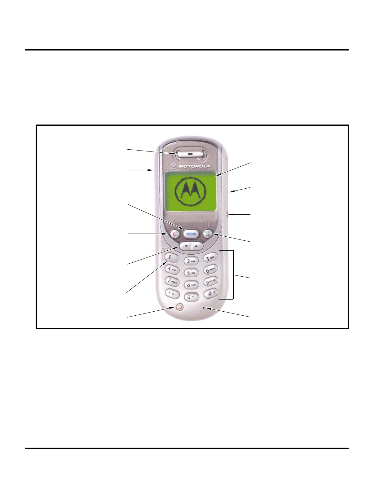
Controls, Indicators, and Input / Output (I/O) Connectors
The PF B95 and C21 telephones’ controls are located on the front and side of the
device, and on the keyboard as shown in Figure 1. Indicators, in the form of icons,
are displayed on the LCD (see Figure 2).
EARPIECE
GRAPHIC DISPLAY
96 x 64 display, 4 lines of text,
INTERNAL ANTENNA
1 line of icons
MENU KEY
Press to access menu
options, press and hold to
enter the Quick Access
menu
CLEAR KEY
Reject call, erase text,
or exit the current screen
Function as navigation keys
when not in idle or call session,
functions as volume during
SCROLL KEY
idle and call session
VOICEMAIL
Press and hold 1 to
retrieve voice messages
POWER BUTTON
Figure 1. PF B95 and C21 Telephone Controls and Indicators Locations
Menu Navigation
PF B95 and C21 telephones are equipped with a simplified icon and list-based user
interface. The phone also features a user-definable Quick Access menu that is
accessed by holding down the MENU key. See Figure 3 for details of the PF B95
and C21 menu structure.
POWER JACK
HEADSET JACK
OK / RECORD KEY
Accept call, setting, option. Press
and hold to access phonebook
KEYPAD
Preset favorite phone numbers for
one-touch dialing.
Preset favorite sites for one-touch
dialing during a WAP session
MICROPHONE
010502o
Liquid Crystal Display (LCD)
The LCD provides an 800 square millimeter green backlit display having useradjustable contrast for optimum readability in all light conditions. The large bitmapped 96 x 64 pixel display includes up to 4 lines of text, use r-adjustable to 2 li nes
with the zoom feature, and 1 line of icons.
10 July 27, 2001 6881038B70
Page 15
Level III Service Manual General Operation
Display animation makes the phone’s icon menu move smooth ly as the user scrol ls
up and down.
Whether a phone displays all indicators depends on the programming and services
➧
to which the user subscribes.
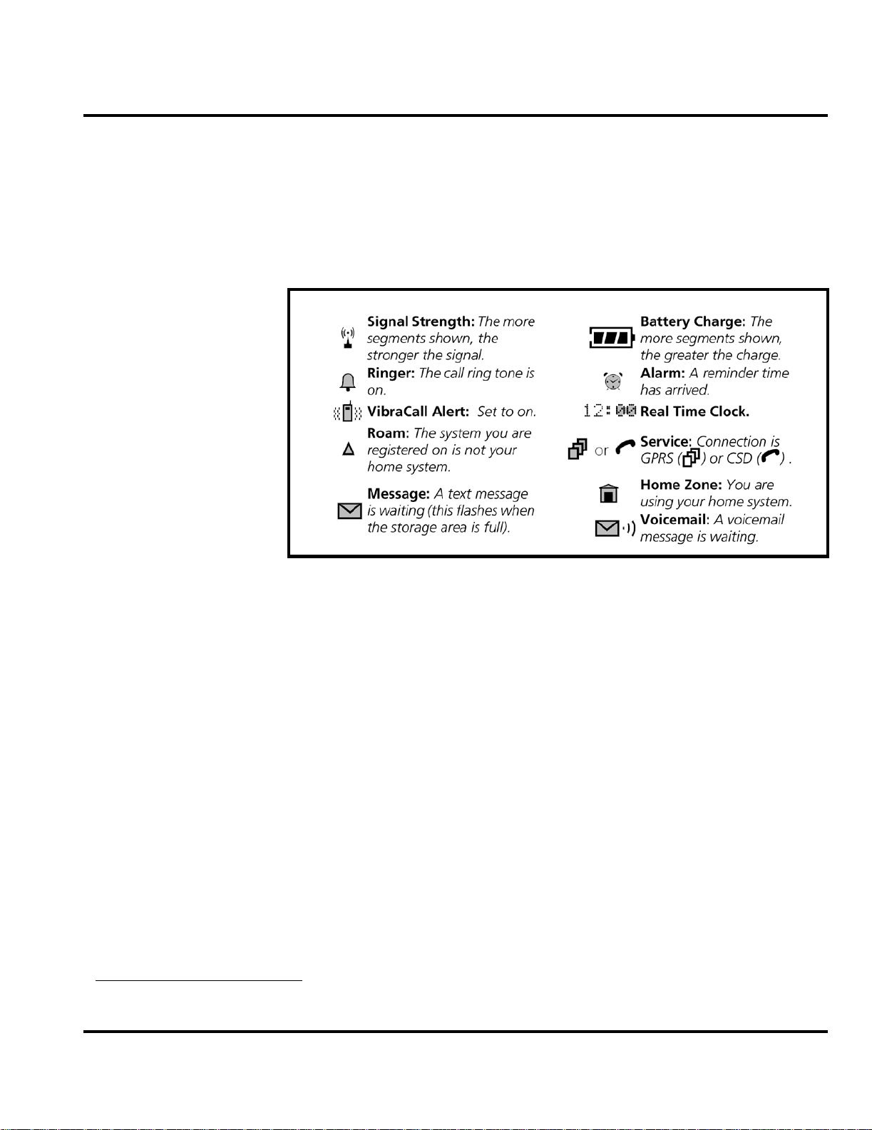
Figure 2 shows some common icons displayed on the LCD.
010503o
Figure 2. T193 Icon Indicators
1. Signal Strength shows the strength of the phone’s connection with the
network. Calls cannot be sent or received when the “no signal” indicator is
displayed.
2. Ringer indicates whether the phone’s ringer is enabled or disabled.
3. Vibrate shows whether the phone’s vibrator alert is enabled or disabled.
4. Roam icon appears when the phon e uses another network system outside th e
user’s home network. When le aving the home network area, the phone roams,
or seeks, anoth e r network.
5. Message
6. Battery Charge Indicator shows the amount of charge left in the battery.
7. Alarm indicates whether the phone’s alarm is on or off.
8. Real Time Clock shows the current time.
9. Service
in CSD mode.
10. Home Zone icon is on when the phone is registered in the user’s ho m e area .
11. Voicemail
4
indicator appears when the phone receives a text message.
4
icon shows phone is currently functioning in either GPRS mode or
4
icon indicates a voicemail message has been received.
4. Network, subscription and SIM card or service provider dependent feature. Not available in all areas.
6881038B70 July 27, 2001 11
Page 16
General Operation Product Family C21
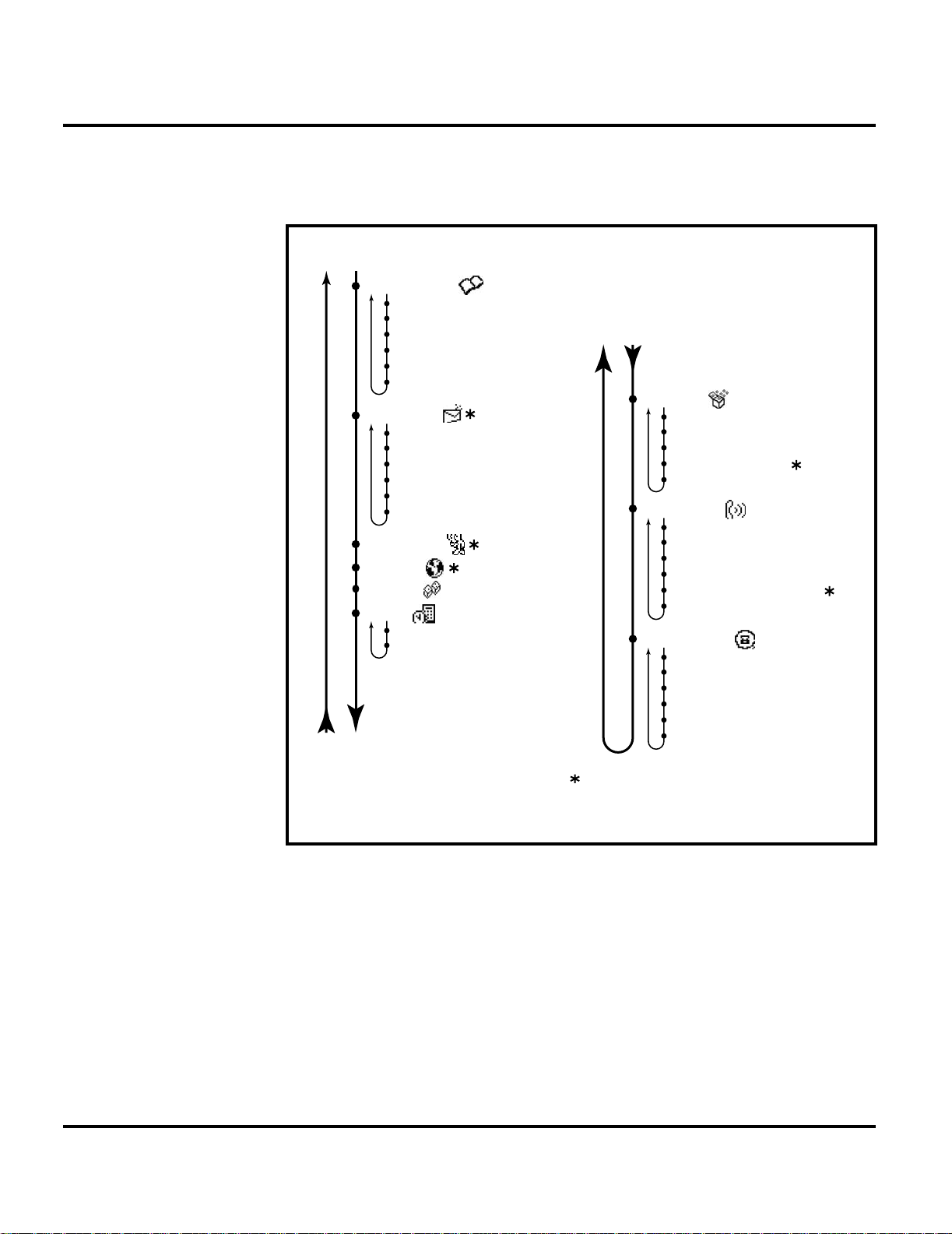
User Interface Menu Structure
Figure 3 shows the T193 telephone menu structure.
User Menu
Phone Book
Personal Numbers
Voice Dialing
My Phone Number(s)
Copy Between SIM & Phone
One-Touch Dial Setting
Show Services
Settings
Messages
Create Messages
Received Messages
Outgoing Messages
Call Voicemail
Cell Broadcast
Message Settings
Chat Room
Internet
Game
Tools
Reminder
Calculator
Phone Setup
Time / Date
Security
Network Selection
Accessory Setup
Ring T ones
Adjust Ring Volume
Ring or Vibrate
Set Ringer Tone
Set Ringer Tone 2
Set Message Alert Tone
Call Groups
Recent Calls
Last Ten Calls
Show Call Charges
Show Call Timers
Set In-Call Display
Call Charge Settings
Lifetime Timer
Feature is network, subscription, or
service provider dependent and may
not be available in all areas. Refer to
User Guide for further information.
010504o
Figure 3. T193 Menu Structure
Alert Settings
In addition to 11 preset ring tones, PF B95 and C21 telephon es allow the user to
download 2 additional ring tones via SMS to your PC. (Availability is carrier and
Network dependant).
Motorola PF B95 and C21 phones incorporate the VibraCall® discreet vibrating
alert that helps to avoid disturbing others when a ringing phone is unacceptable.
Alerts can be set to ring only, vibrate only, vibrate then ring, or no ring or vibrate
Additionally, the profiling feature allows users to identify incoming calls by a
specific ringer tone.
12 July 27, 2001 6881038B70
Page 17

Level III Service Manual General Operation
Battery Fu nction
Battery Charge Indicator
The telephone displays a battery charge indicator icon in the idle screen to indicate
the battery charge level. The gauge shows four levels: 100%, 66%, 33%, and Low
Battery.
Battery Removal
Removing the battery causes the device t o immediately shut down and any pending
work (partially entered phone book entries or outgoing messages, for example) is
lost.
All batteries can cause property damage and/or bodily injury such as burns if a
conductive material such as jewelry, keys, or beaded chains touch exposed terminals.
E
The conductive material may complete an electrical circuit (short circuit) and
become quite hot. Exercise care in handling any charged battery, particularly when
placing it inside a pocket, purse, or other container with metal objects.
Operation
G
➧
If the battery is removed while receiving a message, the message will be lost.
To ensure proper memory retention, turn the phone OFF before removing the
battery. Immediately replace the old battery with a fresh battery.
For detailed operating instructions, refer to the appropriate User Guide listed in
the Related Publications section toward the end of this manual.
6881038B70 July 27, 2001 13
Page 18

General Operation Product Family C21
14 July 27, 2001 6881038B70
Page 19

1 and 2
Level III Service Manual Tools and Test Equipment
6881038B70
B95 and C21
Tools and Test Equipmen t
The following tables list the tools and test equipment used on PF B95 and C21
telephones. Use either the listed items or equivalents.
Table 1. General Test Equipment and Tools
Motorola
Part Number
See Table 6 Charger Used to charge battery and to power device
0180386A82
8102430Z04 GSM / DCS / PCS Test SIM Used to enable manual test mode
6680388B67 Disassembly tool, plastic with flat and pointed
6680388B01 Tweezers, plastic Used during assembly/disassembly
RSX4043-A Torque Driver Used to remove and replace screws
HP34401A
1. To order in North America, contact Motorola Aftermarket and Accessories Division (AAD) by phone at (800) 422-4210 or
FAX (800) 622-6210; Internationally, AAD can be reached by calling (847) 538-8023 or faxing (847) 576-3023.
2. Not available from Motorola. To order, contact Hewlett Packard at (800) 452-4844.
—
1
Antistatic Mat Kit (include s 66-80387A 95 antis tatic
mat, 66-80334B36 groun d cord, and 42- 80385A59
wrist band)
ends (manual opening tool)
Torque Driver Bit T-6 Plus, Apex 440-6 IP Torx Plus
or equivalent
2
Digital Multimeter Used to measure battery voltage
Description Application
Provides protect ion from damage to de vice caused
by electrostatic discharge (ESD)
Used during assembly/di s assembly of device
Used with torque driver
6881038B70 July 27, 2001 15
Page 20

Disassembly Product Family C21
Disassembly
The procedures in this section p rovide inst ructions for t he disassembl y of a PF B95
or C21 telephone. Tools and equipment used are listed in Table 1, preceding.
Many of the integrated devices used in this equipment are vulnerable to damage
G
G
Removing and Replacing the Battery Cover and Battery
E
from electrostatic discharge (ESD). Ensure adequate static protection is in place
when handling, shipping, and servicing the internal components of this equipment.
Avoid stressing the plastic in any way to avoid damage to either the plastic or
internal components.
All batteries can cause property damage and/or bodily injury such as burns if a
conductive material such as jewelry, keys, or beaded chains touch exposed terminals.
The conductive material may complete an electrical circuit (short circuit) and
become quite hot. Exercise care in handling any charged battery, particularly when
placing it inside a pocket, purse, or other container with metal objects.
1. Ensure the phone is turned off.
2. Depress the battery cover release, slide the battery cover in the direction of the
arrow, and lift completely off the phone (see Figure 4).
BATTERY COVER
BATTERY
COVER
RELEASE
REAR HOUSING
010505o
Figure 4. Removing the battery cover
16 July 27, 2001 6881038B70
Page 21

Level III Service Manual Disassembly
BATTERY
REAR HOUSING
E
010506o
Figure 5. Removing the battery
3. Remove the battery by lifting its bottom end from the battery compartment
and sliding it down and away from the compartment as shown in Figure 5.
There is a danger of explosion if the Nickel Metal Hydride battery is replaced
incorrectly. Replace only with the same type of battery or equivalent as recommended
by the battery manufacturer. Dispose of used batteries according to the manufacturer’s instructions.
4. To replace, align the battery with the battery compartment so the terminals
on the battery match the battery contacts in the phone.
5. Slide the top of the battery into the receptacle molded into the housing, then
press the bottom end of the battery securely into the battery compartment.
6. Line up the battery cover with the rear housing then slide it forward until it
snaps into place.
6881038B70 July 27, 2001 17
Page 22

Disassembly Product Family C21
Removing and Replacing the Subscriber Identity Module (SIM)
1. Remove the battery cover and battery as described in the procedures.
2. As shown in Figure 6, slide the SIM retaining clip in the d irection of the arrow
to unlock.
3. Rotate the SIM upward and slide it out.
SIM RETAINING CLIP
SIM
REAR HOUSING
010507o
Figure 6. Removing the SIM
4. To replace, carefully insert the SIM into its socket. Be sure the SIM is correctly
positioned to contact the terminals in the phone.
5. While holding the SIM in its socket, slide the SIM retaining clip to lock in place.
6. Replace the battery and battery cover as described in the procedures.
18 July 27, 2001 6881038B70
Page 23

Level III Service Manual Disassembly
Removing and Replacing the Front Cover (Convertible Cover)
1. Remove the battery cover and battery as described in the procedures.
2. Using the flat end of t he di sas sembl y to ol in t he i nden tati o n on the bott om of
the phone, carefully separate the front cover from the rear housing. See
Figure 7.
FRONT COVER
REAR HOUSING
010508o
Figure 7. Removing the front cover
3. Lift the front cover upward and slide as show n to release its top edge from the
rear housing. Lift the front cover completely off the phone.
4. To replace, hook the top of the front co ver ont o the rea r housi ng and press on
the front cover’s bottom edge until it snaps into place.
5. Replace the battery and battery cover as described in the procedures.
6881038B70 July 27, 2001 19
Page 24

Disassembly Product Family C21
Removing and Replacing the Keypad
1. Remove the battery cover, battery, and front cover as described in the procedures
.
2. Lift the keypad from the front cover as shown in Figure 8.
KEYPAD
FRONT COVER
DISASSEMBLY TOOL
010509o
Figure 8. Removing the keypad
3. To replace, insert the keypad into the front cover. Ensure the keys align
properly with the openings and the keypad is fully seated in the front cover.
4. Replace the front cover, battery, and battery cover as described in the procedures.
20 July 27, 2001 6881038B70
Page 25

Level III Service Manual Disassembly
Removing and Replacing the Transceiver Board Assembly
1. Remove the battery cover, battery, and front cover as described in the procedures
.
This product contains static-sensitive devices. Use anti-static handling procedures
G
to prevent electrostatic discharge (ESD) and component damage.
2. Using the Torx driver and T-6 bit, remove the 6 screws shown in Figure 9. Set
the screws aside for reuse.
T-6 SCREW, 6 PLACES
TRANSCEIVER
BOARD ASSEMBLY
REAR HOUSING
DISASSEMBLY TOOL
010510o
Figure 9. Removing the transceiver board assembly
3. Using the flat e nd of the disa ssembl y tool, ca reful ly pry the transc eiver boa rd
assembly from the rear housing. The board assembly should separate easily
from the rear housing.
4. Lift the transceiver board assem bly completely away from the rear housing.
5. To replace, align the transceiver board assembly with the rear housing and
press into place.
6881038B70 July 27, 2001 21
Page 26

Disassembly Product Family C21
6. After ensuring the transceiver board assembly is properly seated in the rear
housing, insert and tighten the 6 screws. Do not overtighten.
7. Replace the front cover, battery, and battery cover as described in the procedures.
Removing and Replacing the Cover Plate
1. Remove the battery cover, battery, front cover, and transceiver board assembly
G
as described in the procedures
This product contains static-sensitive devices. Use anti-static handling procedures
to prevent electrostatic discharge (ESD) and component damage.
2. Using the flat end of the disassembly tool, care fully disengage the 2 cover pl ate
catches from the transceiver board.
.
G
The cover plate is reusable. Do not bend the catches permanently.
COVER PLATE
COVER PLATE
CATCH, 2 PLACES
Figure 10. Removing the cover plate
3. Carefully lift the cover plate from the transceiver board assembly as shown in
Figure 10.
4. To replace, align the cover plate with the transceiver board assembly and press
together until the catches snap into place. Ensure the cover plate is properly
aligned and flat against the transceiver board assembly.
5. Replace the transceiver board assembly, front cover, battery, and battery cover
as described in the procedures.
BOARD ASSEMBLY
DISASSEMBLY TOOL
TRANSCEIVER
010512o
22 July 27, 2001 6881038B70
Page 27

Level III Service Manual Disassembly
Removing and Replacing the Display Module
The flexible printed cable (FPC or flex) connecting the display module to the
G
transceiver board is easily damaged. Exercise extreme care when handling.
1. Remove the battery cover, battery, front cover, transceiver board assembly,
and cover plate as described in the procedures
2. Locate the 2 display module mounting tabs shown in Figure 11.
.
DISPLAY MODULE
MOUNTING TAB, 2 PLACES
G
DISASSEMBLY TOOL
DISPLAY MODULE
TRANSCEIVER
BOARD
DISPLAY FLEX
010513o
Figure 11. Removing the display module
The display module is attached to the transceiver board with the flex. Do not attempt
to separate the module from the board until the flex has been disconnected as
described in the following steps.
6881038B70 July 27, 2001 23
Page 28

Disassembly Product Family C21
3. Using the flat end of the disassembly tool, gently pry the tabs away from the
transceiver board to release the display module.
LOCKING TAB
FLEX
TRANSCEIVER
BOARD
DISASSEMBLY TOOL
FLEX
CONNECTOR
DISPLAY
MODULE
010514o
Figure 12. Removing the display module assembly
4. While holding the display module slightly away from the transceiver board,
use the pointed end of the disassembly tool to disengage the 2 flex connector
locking tabs as shown in Figure 12.
5. Pull the flex straight out of the connector, then lift the display module
completely away from the transceiver board.
6. To replace, insert the end of the di splay module fl ex into the conn ector on the
transceiver board. After ensuring the flex is straight and fully seated in the
connector, use the disassembly tool to push the locking tabs until completely
engaged.
7. Line up the display modul e mounti ng tabs with t he co rresp onding no tch es in
the transceiver board , then press together until the displ ay module snaps into
place.
8. Replace the cover plate, transceiver board assembly, front cover, battery, and
battery cover as described in the procedures.
24 July 27, 2001 6881038B70
Page 29

Level III Service Manual Disassembly
Removing and Replacing the Alert Grommet
1. Remove the battery cover, battery, front cover, transceiver board assembly,
cover plate, and display module as des cribed in the procedures
2. Using the flat end of t he disassembly tool, carefully pry the alert grommet from
the alert transducer. The grommet should come away easily. See Figure 13.
ALERT GROMMET
DISASSEMBLY TOOL
TRANSCEIVER BOARD
.
010515o
Figure 13. Removing the alert grommet
3. To replace, stretc h the grommet over the alert transducer until it is in place.
4. Replace the display module, cover plate, transceiver board assembly, front
cover, battery, and battery cover as described in the procedures.
6881038B70 July 27, 2001 25
Page 30

Disassembly Product Family C21
Removing and Replacing the Microphone Grommet and Microphone
1. Remove the battery cover, battery, front cover, transceiver board assembly,
and cover plate as described in the procedures
2. Using the flat end of the disassembly tool, carefully pry the microphone
grommet from the microphone as shown in Figure 14. The grommet sho u ld
come away easily.
.
TRANSCEIVER BOARD
MICROPHONE
GROMMET
G
DISASSEMBLY
TOOL
MICROPHONE
PLASTIC
TWEEZERS
010516o
Figure 14. Removing the microphone grommet and microphone
3. Using the plastic tweezers to grasp the microphone, pull the microphone
straight out of its socket.
The microphone leads are easily bent or broken. Use care to prevent damage when
handling. The microphone is keyed to fit on the board only one way and will prevent
proper board mounting if installed incorrectly.
4. To replace, inser t the microphone leads into the socket on th e transceiver board
and carefully press straight down until fully seated.
5. Replace the cover plate, transceiver board assembly, front cover, battery, and
battery cover as described in the procedures.
26 July 27, 2001 6881038B70
Page 31

Level III Service Manual Disassembly
Removing and Replacing the Vibrator
1. Remove the battery cover, battery, front cover, and transceiver board assembly
as described in the procedures
2. Using the flat end of the disassembly tool, carefully pry the vibrator from its
cavity in the rear housing. The vib rator should come away easily from th e rear
housing. See Figure 15.
.
VIBRATOR
REAR HOUSING
DISASSEMBLY TOOL
010517o
Figure 15. Removing the vibrator
3. To replace, insert the vibrator into the rear housing. Ensure the vibrator
terminals are properly aligned to contact the corresponding pads on the
transceiver board.
4. Replace the transceiver board assembly, front cover, battery, and battery cover
as described in the procedures.
6881038B70 July 27, 2001 27
Page 32

Subscriber Identity Module (SIM) and Identification Product Family C21
Subscriber Identity Module (SIM) and Identification
SIM
A SIM is required to access the existing local GSM network, or remote networks
when traveling (if a roaming agreement has been made with the provider).
The SIM card contains:
• All the data necessary to access GSM services
• The ability to store user information such as phone numbers.
• All information required by the network provider to provide access to the net-
work.
Identification
Each Motorola GSM device is labelled with a variety of identifying numbers. The
following information describes the current identifying labels.
Mechanical Serial Number (MSN)
The Mechanical Serial Number (MSN) is an individual unit identity number and
remains with the unit throughout the life of the unit.
The MSN can be used to log and track a unit on Motorola's Service Ce nter Database.
The MSN is divided into 4 sections as shown in Figure 16.
MSN 10 Digits
3 Digits 1 Digit 2 Digits 4 Digits
APC DC DC SNR
Account Product Code
i.e. StarTAC Phone130
TM
Distribution Center
i.e. Easter Inch
Date Code: Year and
Month of Shipment
Unit's individual serial
number
000807a
Figure 16. MSN label breakdown
28 July 27, 2001 6881038B70
Page 33

Level III Service Manual Subscriber Identity Module (SIM) and Identification
International Mobile Station Equipment Identity (IMEI)
The International Mobile station Equipment Identity (IMEI) number is an individual number unique to the PCB and is s tored within the unit's memory. The following
diagram illustrates the various parts of this number.
IMEI 16 Digits
6 Digits 2 Digits 6 Digits 2 Digits
TAC FAC SNR IU
Type Approval Code Distribution Center
factory code
Individual PCB Serial
Number
Internal Use - spare
digits
000808o
Figure 17. IMEI label breakdown
Other label number configurations present are:
• TRANSCEIVER NUMBER: Identifies the product type. Normally the SWF
number. (i.e. V100).
• PACKAGE NUMBER: Identifies the equipment type, mode, and language in
which the product is shipped.
6881038B70 July 27, 2001 29
Page 34

Troubleshooting Product Family C21
Troubleshooting
Manual Test Mode
Motorola PF B95 and C21 telephones are equipped with a manual test mode
capability. This allows service personnel to verify functionality and perform fault
isolation by entering keypad commands.
To enter the manual test command mode, a GSM / DCS / PCS test SIM must be used.
1. Press , to turn the phone OFF.
2. Remove the battery as described in the procedures.
3. Remove the customer’s SIM card from the phone as described in the procedures.
4. Insert the test SIM into the SIM slot.
5. Replace the battery as described in the procedures.
6. Press , to turn the phone ON.
Press and hold the # button for approximately 3 seconds until TEST displays on the
screen. The phone may now be issued test commands listed in T able 2.
Manual Test Mode Commands
Table 2. Test Commands
Test Command Test Function/Name
Press and hold # for 2 seconds Enter manual test mode
01# Exit manual test mode
07x# Mute RX audio path
08# Unmute RX audio path
09# Mute TX audio path
10# Unmute TX audio path
15x# Generate tone
1590# Vibrate Mode
1591# Ringer Mode
16# Mute tone generator
19# Displ ay so ftware version number of Call Processor
20# Displ ay so ftware version number of Modem
36# Initiate acoustic loopback
360# Full Rate
361# Enhanced Full Rate
362# Half Rate
37# Stop test
38# Activate Mini SIM
39# Deactivate Mini SIM
43x# Change audio path
47x# Set audio volume
51# Enable sidetone
30 July 27, 2001 6881038B70
Page 35

Level III Service Manual Troubleshooting
Table 2. Test Commands (Continued)
Test Command Test Function/Name
52# Disable sidetone
54# Show service indicator LED (0 - Off, 1 - Red, 2 - Green, 3 - Amber) (flip must be closed)
57# Initialize non-volatile memory
58# Display security code
58xxxxxx# Modify secur ity code
59# Displ ay lo ck code
59xxx# Modify lock code
60# Displ ay IMEI
980# DCS Mode (PF B95 only)
981# GSM Mode (PF B95 only)
962# PCS Mode (PF C21 only)
99# Displ ay all pixels
Troubleshooting Chart
Table 3. PF B95 and C21 Telephone: Level II Troubleshooting Chart
SYMPTOM PROBABLE CAUSE VERIFICATION AND REMEDY
1. Telephone will not turn on or stay on. a) Battery either discharged or
2. Telephone exhibits poor reception or
erratic operation such as calls frequently
dropping or weak or distorted audio.
3. Display is erratic, or provides partial or
no display.
defective.
b) Battery terminals open or
misaligned.
c) Transceiver board assembly
defective.
Transceiver board assembly defective. Replace the transceiver board assembly (refer
a) Mating connections to or from
transceiver board faulty.
b) Transceiver board assembly
defective.
Measure battery voltage across a 50 ohm (>1
Watt) load. If the battery voltage is <3.25 Vdc,
recharge the battery using the appropriate
battery charger. If the battery will not recharge,
replace the battery. If battery is not at fault,
proceed to b.
Visually inspect the battery terminals on both
the battery and the telephone. Realign and, if
necessary, either replace the battery or refer to
a Level 3 Service Center for the battery
connector replacement. If battery terminals are
not at fault, proceed to c.
Remove the transceiver board assembly.
Substitute a known good assembly and
temporarily reassemble the unit. Depress the
PWR button; if unit turns on and stays on,
disconnect the dc po wer s ource and reas sembl e
the telephone with the new transceiver board
assembly. Verify that the f aul t ha s be en c le are d.
to 1c). Verify that the fault has been cleared and
reassemble the unit with the new transceiver
board assembly.
Check general condition of flex and flex
connector if the flex and connector are good,
check that the connector locking tabs are fully
engaged. If faulty connector, replace the
transceiver board assembly. If connector is not
at fault, proceed to b.
Replace the transceiver board assembly (refer
to 1c). Verify that the fault has been cleared and
reassemble the unit with the new transceiver
board assembly.
6881038B70 July 27, 2001 31
Page 36

Troubleshooting Product Family C21
Table 3. PF B95 and C21 Telephone: Level III Troubleshooting Chart (Continued)
SYMPTOM PROBABLE CAUSE VERIFICATION AND REMEDY
4. Incoming call alert transducer audio
distorted or volume is too low.
5. Telephone transmit audio is weak.
(usually indicated by called parties
complaining of difficulty in hearing voice).
6. Receive audio from earpiece speaker is
weak or distorted.
7. Telephone will not recognize or accept
SIM card.
8. Vibrator feature not functioning. a) Vibrator defective. Replace vibrator as described in the
9. Internal Charger not working. Faulty charger circuit on transceiver
10. No or weak audio when using headset. a) Headset plug not pushed fully
Faulty transceiver board assembly. Replace the transceiver board assembly (refer
a) Microphone defective. Replace the microphone as described in the
b) Transceiver board assembly
defective.
a) Connections to or from transceiver
board assembly defective.
b) Earpiece speaker defective. Temporarily replace the LCD speaker assembly
c) Transceiver board assembly
defective.
a) SIM card defective. Check the SIM card contacts for dirt. Clean if
b) Transceiver board assembly
defective.
b) Transceiver board assembly
defective.
board assembly.
home.
b) Faulty jack on transceiver board
assembly.
to 1c). Verify that the fault has been cleared and
reassemble the unit with the new transceiver
board assembly.
procedures. If fault is not cleared, pro ceed to b.
Replace the transceiver board assembly (refer
to 1c). Verify that the fault has been cleared and
reassemble the unit with the new transceiver
board assembly.
Check connection from the earpiece to the
transceiver board assembly. If connection is not
at fault, proceed to b.
with a known good assembly. Ensure good
connection. Place a c all an d verify improvement
in earpiece audio . If fault is cleared, reassemble
the phone with the good assembly. If fault is not
cleared, proceed to c.
Replace the transceiver board assembly (refer
to 1c). Verify that the fault has been cleared and
reassemble with the new transceiv er boa rd
assembly.
necessary, and check if fault has been cleared.
If the contacts are clean, insert a known good
SIM card into the telephone. Power up the unit
and confirm that the card has been accepted. If
the fault no longer exists, replace the defective
SIM card. If the SIM card is no t at fault, proceed
to b.
Replace the transceiver board assembly (refer
to 1c). Verify that the fault has been cleared and
reassemble the unit with the new transceiver
board assembly.
procedures. If the fault has not been cleared,
proceed to b.
Replace the transceiver board assembly (refer
to 1c). Verify that the fault has been cleared and
reassemble the unit with the new transceiver
board assembly.
Test a selection of batteries in the rear pocket of
the desktop charger. Check LED display for the
charging indications. If these are charging
properly, then the internal charger is at fault.
Replace the transceiver board assembly (refer
to 1c). Verify that the fault has been cleared and
reassemble the unit with the new transceiver
board assembly.
Ensure the headset plug is fully seated in the
jack.
Replace the transceiver board assembly (refer
to 1c). Verify that the fault has been cleared and
reassemble the unit with the new transceiver
board assembly.
32 July 27, 2001 6881038B70
Page 37

Level III Service Manual Troubleshooting
Programming: Software Upgrade and Flexing
Contact your local technica l support engineer for i nformation about equipment and
procedures for flashing and flexing.
6881038B70 July 27, 2001 33
Page 38

Part Number Charts Product Family C21
Part Number Charts
The following charts are provided as a reference for the parts associated with PF
B95 and C21 telephones.
Related Publications
Motorola T192 Wireless Phone User Guide, English 9870290Fxx
Motorola T193 Wireless Phone User Guide, English 9888164K95
Motorola T193 Wireless Phone User Guide, Spanish 9889883L01
34 July 27, 2001 6881038B70
Page 39

Level III Service Manual Part Number Charts
Exploded View Diagram
1
2
9
3
10
4
11
5
6
7
8 15
12
13
14
010448o
Figure 18. Exploded View Diagram
6881038B70 July 27, 2001 35
Page 40

Part Number Charts Product Family C21
Exploded View Parts List
Table 4. Exploded View Parts List
Item
Number
1 See Table 5 Front housing kit 9 See Table 5 Keypad
2 02093158B07 Screw, mounting, 6 places 10 0104119F76 Cover plate assembly
3 0104119F79 LCD speaker assembly 11 0586501P01 G rommet, microphone
4 0586500P01 Grommet, transducer 12 5009135L07 Microphone
5 Note 1 Antenna assembly, internal 13 See Table 5 Transceiver board
6 0186475P01 Rear housing assembly 14 0186497P01 Vibrator assembly
7 0586470P01 RF plug 15 See Table 6 Battery
8 AAHN5385 Battery cover, Gray
Notes: 1. Order next higher assembly, item 13.
Motorola Part
Number
Description
Item
Number
Motorola Part
Number
Description
There is a danger of explosion if the Nickel Metal Hydride battery pack is replaced
incorrectly. Replace only with the same type of battery or equivalent as recommended
E
by the battery manufacturer. Dispose of used batteries according to the manufacturer’s instructions.
Model-Specific Part Numbers
Table 5. Model-Specific Part Numbers
Item
Number
1 Front co ver kit, Magic Green AAHN5383
1 Front cover kit, Silver Mist AAHN5398
1 Front co ver kit, Graphite Gray AAHN5399
9 Keypad, Generic 7586482P01
9 Keypad, Stroke 7586482P02
9 Keypad, BoPoMoFo 7586482P03
13 Transceiver board, GSM / DCS (PF B95) 8486506P01
13 Transceiver board, PCS (PF C21) 8486506P02
Part Description Part Number
36 July 27, 2001 6881038B70
Page 41

Level III Service Manual Part Number Charts
Accessories
Table 6. Accessories
Item
Number
1 Front cover kit, Limewash SYN9309
1 Front cover kit, Nordic Teal SYN9310
1 Front co ver kit, Orange Glow SYN9311
15 Battery, 600 mAh NiMH, English label AANN4106
15 Battery, 600 mAh NiMH, Chinese label SNN5628
— Travel charger, 300 mAh economy with fixed plugs, UK SPN4680
— Travel charger, 300 mAh economy with fixed plugs, US SPN4681
— Travel charger, 300 mAh economy with fixed plugs, Euro 220 SPN4682
— Travel charger, 300 mAh economy with fixed plugs, Australia SPN4683
— Travel charger, 300 mAh economy with fixed plugs, India 5 Amp SPN4684
— Travel charger, mid-rate switching with fixed plugs, Brazil SPN4835
— Vehicle power adapter (VPA) SYN8087
— Hands free car kit, easy install SYN8543
— Headset, Translucent Blue AAYN4207
— Headset, Translucent Gray AAYN4208
— Headset, Neon Green AAYN4262
— Headset, Neon Blue AAYN4263
— Headset, mono with boom microphone SYN8146
— Headset, mono, retractable SYN8284
— Headset, ear bud, silver AAYN4264
Part Description Part Number
6881038B70 July 27, 2001 37
Page 42

Part Number Charts Product Family C21
38 July 27, 2001 6881038B70
Page 43

1 and 2
Index
Level III Service Manual Index
B95 and C21
6881038B70
Index
A
alert grommet, removing and replacing 25
alert settings
B
battery
charge indicator
function
battery cover, removing and rep lac in g
battery, removing and replacing
C
caller ID 9
Canadian Interference-Causing Equipment regulations
changes
product
commands, manual test mode
copyrights
computer software
cover plate, removing and replacing
D
disassembly 16
display flex, disconnecting
display module, removing and replacing
E
exploded view diagram 35
exploded view parts list
F
FCC rules 1
features
caller ID
chat messaging
SIM Toolkit
text entry
voice recognition
Wireless Access Protocol (WAP)
front cover, removing and rep laci ng
I
identification
international mobile stati on equ ipm ent ide nti ty
12
13
13
16
16
1
30
2
22
23
23
36
9
9
9
9
8
8
19
29
mechanical serial number
product
identification, labels
IMEI
29
Introduction
1
28
1
28
K
keypad, removing and replacing 20
L
LCD 10
liquid crystal display (LCD)
10
M
manual test mode 30
menu structure
1
microphone grommet, removing and replacing
microphone, removing and replacing
model-specific part numbers
MSN
28
12
36
N
names
product
1
O
operation 10
alert settings
battery
controls, indicators, and I/O connectors
icons
11
alarm
battery charge indicator
home zone
message
real time clock
ringer
roam
service
signal strength
vibrate
voicemail
LCD
10
menu navigation
menu structure
overview, product
12
13
11
11
11
11
11
11
11
11
11
11
10
12
7
26
26
10
11
6881038B70 July 27, 2001 Index-1
Page 44

Index Product Family C21
P
parts
exploded view diagram
exploded view parts list
model-specific part numbers
replacement
product
changes
identification
names
product overview
features
publications, related
34
1
1
1
7
7
34
35
36
R
regulatory agency compliance 1
related publication s
removing
alert grommet
battery
battery cover
cover plate
display module
front cover
keypad
microphone
microphone grommet
SIM
transceiver board
vibrator
replacement parts
ordering
replacing
alert grommet
battery
battery cover
cover plate
display module
front cover
keypad
microphone
microphone grommet
SIM
transceiver board
vibrator
revisions
service manual
13, 16
20
18
27
4
16
20
18
27
34
25
16
22
23
19
26
26
21
25
16
22
23
19
26
26
21
3
36
S
serial number
mechanical
service manual
about
audience
conventions
revisions
scope
service policy
customer support
out of box failure
product support
shut down
upon battery removal
SIM Toolkit
SIM, description
SIM, removing and replacing
specifications
subscriber identity module (SIM)
support
customer
product
28
2
2
3
3
2
3
4
3
3
13
9
28
18
5
28
4
3
T
test equipment 15
text entry
tools, disassembly
transceiver board, removing and replacing
troubleshooting
9
15
30
manual test mode
manual test mode commands
troubleshooting chart
30
31
30
V
vibrator, removing and repla cing 27
voice recognition
8
W
WAP (Wireless Access Protocol) 8
warranty service
3
21
Index-2 July 27, 2001 6881038B70
Page 45

Page 46

MOTOROLA, the Stylized M Logo, and all other trademarks indicated as such herein are trademarks of Motorola, Inc.
® Reg. U.S. Pat. & Tm. Off.
2001 Motorola, Inc.
All rights reserved.
Personal Communications Sector,
1500 Gateway Blvd.
Boynton Beach, FL 33426-8292
Printed in U.S.A. 07/01
@6881038B70@
6881038B70-A
Page 47

T193 - RF BACK END SCHEMATIC
Page 48

T193 - RX FRONT END SCHEMATIC
Page 49

T193 - AL SCHEMATICS
Page 50

T193 - BOARD LAYOUT PAGE 1/2
Page 51

T193 - BOARD LAYOUT PAGE 2/2
Page 52

T193 - ANTENNA SWITCH SCHEMATIC
Page 53

T193 - SWITCHING CONTROL SCHEMATIC
Page 54

T193 - TRANSCEIVER SCHEMATIC
Page 55

T193 - TRANSMIT AMPLIFIER SCHEMATIC
Page 56

T193 - TRANSMIT / RECEIVE VCO SCHEMATIC
Page 57

"
6
T
,
,
,
,
,
,
,
,
,
,
9
4
6
4
g
8
3
8
-
-
8
8
8
T193 Level 3 Parts List
Part Designator Part Number Part Description Part Type Part Designator Part Number Part Description Part Type
CR248 4809877C10 dio1_60x0_80 Q314 4809939C27 sot2_00x1_25 UMB4NTN,
CR249 4809641F02 sod1_70x1_25 Q490 4809527E41
CR911 4813830M74 sot23-rb Q505 4809939C03 sot2_00x1_25 UMD3NTR,
CR912DNP 4813830M74 sot23-rb Q506 4809939C05 sot1_25x2_00-5pin-lb UMC5NTL,
D101 5102834Y83 dio5_4x4_0_12pin LMSP54, Q804 4809939C23 sot2_00x1_25 UMX1N,
D900 4809653F02 dio1_90x1_90 MBRM120T3 Q900 4813824B11 sot223-rb MMJT9435,
D901 "4809606E02" sc90-rt DAN222T, Q901 "4809579E1
D902 4809653F07 dio1_90x1_90 MBRM120E
DS600 4809496B11 led1_60x0_80 QSMG-H799
DS601 4809496B11 led1_60x0_80 QSMG-H799
DS602 4809496B11 led1_60x0_80 QSMG-H799
DS603 4809496B11 led1_60x0_80 QSMG-H799
DS606 4809496B11 led1_60x0_80 QSMG-H799
DS607 4809496B11 led1_60x0_80 QSMG-H799
DS608 4809496B11 led1_60x0_80 QSMG-H799
DS609 4809496B11 led1_60x0_80 QSMG-H799
DS610 4809496B11 led1_60x0_80 QSMG-H799
DS611 4809496B11 led1_60x0_80 QSMG-H799
FL472 9109674L10 fltr4_45x4_30-7pin 74L10 SH5 2686487P01 shield2686487p01 SHIELD,
FL480DNP 9109450C06 fltr3_0x3_0-6pin 50C06, U200 "510989E78" bga8_00x8_00p80 79E78,
FL490 9109487U02 fltr5_00x3_00-8pin 400MHz, U201 5162852A64 ssop8-sz2_0x2_3 TC7W04FK,
J100 0987378K01 mech0987378k01 SWITCH, U300 4809283D82 osc9_00x8_00_16pin 83D82
J900 "0909195E01" conn0909195e01 CONN_J, U302 "5109731C2
J901 0987850K03 conn0987850k03_
J902 0170297V01 mech0170297v01_
J903 0985882K01 conn0985882k01_
J908 "0909195E01" connpt09pnga19_2
LS900 5002811Y27 acous5085873j01 SPKR, U801 5164824E01 bga6_964x7_286p48 28F320B,
M901 3986492P01 mech3986492p01 CONTACT, U802 5109509A40 bga8_50x7_00p48 CY62147V,
M903 3986491P01 mech3986491p01 CONTACT, U804 "5109522E5
M904 3986491P01 mech3986491p01 CONTACT, U900 "5109879E5
Q101 4809939C07 sotum5-rb-po12346 UMA4N, U903 5109923D52 msoic8 23D52,
Q102 4809939C05 sot1_25x2_00-5pin
Q104 4809939C05 sot1_25x2_00-5pin
Q105 "4809579E48" sot2_90x1_60-6pin FDC6306P, VR901 4809788E06"sod1_70x1_25 UDZTE-176.
Q201 "4809579E48" sot2_90x1_60-6pin FDC6306P, VR902 "4809788E06sod1_70x1_25 UDZTE-176.
Q203 "4809527E41" sotem3-rb 27E41, VR903DNP 4813832P75 sc59-6pin-rb MMQA6V8T3
Q310 4809939C07 sotum5-rb-po12346 UMA4N, Y200 4809612J22 xtal6_00x3_50-po1234 12J22,
Q311 4809939C09 sot2_00x1_25 UMH4N, Y900 4809995L03
Q312 4809939C27 sot2_00x1_25 UMB4NTN,
Q313 4809939C09 sot2_00x1_25 UMH4N,
CONN_J, U432 5109944C43 tqfp4x4p25 MC13748,
CONTACT, U501 5109923D50 lcc21-sz4_00x4_00 23D50,
CONN_J, U506 5102834Y86 lcc17-sz9_1x11_6 PA2001_2G,
CONN_J, U800 5102834Y81 bga15_00x15_00p196 SC56685VH
UMC5NTL, U904 4809939C06 sot2_00x1_25 UMZ2NTR,
UMC5NTL, VR900 4809788E06"sod1_70x1_25 UDZTE-176.
Q902 "4809579E16to236-rb TN0200T,
Q903 4880048M03 sotem3-rt DTC144EE,
Q904 "4809579E29tsop3_00x1_50p6 SI3443,
Q912 "4809579E02sc90-rb 2SK1830,
Q913 "4809579E39sc70-6pin-rb FDG6323L,
Q914 4870370A14 sotem3-rt 70A14,
RT900 0687802K01 res0805 THERM,
SH1 2686483P01 shield2686483p01 SHIELD,
SH2 2686484P01 shield2686484p01 SHIELD,
SH3 2686485P01 shield2686485p01 SHIELD,
SH4 2686486P01 shield2686486p01 SHIELD,
sotem3-rb 27E41,
to236-rb TN0200T,
sot23-5-rb MAX4250,
sot1_25x2_00-5pin-rb NC7SZ125,
bga10_00x10_00p100 79E58,
 Loading...