

Page 1
02AZD880C User Manual
Product U-WAVE-T Buzzer type
Model 02AZD880C
FCC ID VXU-02AZD880C
IC 4396B-02AZD880C
Page 2
U-WAVE-T
Introduction
The U-WAVE-T is a wireless com munication tool for transmit ting measurement data to t he Mitutoyo
U-WAVE-R (option) by connect ing to a Digimatic-output interf aced tool with the supplied connectin g
cable.
The U-WAVE-T is also categorized into two types: IP67 type and buzzer type. To obtain the
highest performance and t he longest service life from the U-W AVE-T, carefull y read this User’s Manual
thoroughly prior to use.
specifications of the U-WAVE-T and descriptions in this manual are subject to change without prior
notification.
Safety Precautions
Use the U-WAVE-T in conformanc e with the specifications, functio ns and precautions for use given in thi s
manual. If the U-WAVE-T is use d in other way, it may jeopardize saf ety.
• Do not use the U-WAVE-T near a medical devic e that has a possibility of causing a
malfunction due to radio waves.
• The U-WAVE-T using an electric wave has a possibility that communication is interrupted
!
WARNING
Notes on Export Regulations
WARNING
Precautions for the Wireless Law
The country (region) that can use The U-WAVE-T (IP67 type and buzzer type) by the code No. and
Use excluding the country (region) specified by the certification number is prohibited by the law.
WARNING
Precaution for 02AZD730C, 02AZD880C ( U.S.A and Canada type)
Notes
Precautions on Wireless Communication En viron ments
under the influence of exter nal noises, etc., even within the distance of communication of the
electric wave. In this case take s ufficient failure preventio n action (security measures).
• In the ev ent the U-WAVE-T sh ould fail, take suffici ent failure prevention act ion (security
measures).
• Do not disa ssemble, short, modi fy, or heat the supplie d battery. The leaked contents may get
into your eyes. Also, heat generat ion or explosion may result.
• The battery used in the U-WAVE-T contains an irritating substance.
Should this liquid substanc e be applied to your eyes or skin by accide nt, immediately rinse it
away in clean water.
• Should the batte ry be swallowed by accident, im mediately rinse the mout h out and induce
vomiting the battery while drin king a large amount of water. Af ter then consult a doctor.
The U-WAVE-T falls int o the Catch-All-Contr olled Goods or Program under the Category 16 of
!
the Separate Table 1 of the E xport Trade Control Order or t he Category 16 of the Separat e
Table of the Foreign Excha nge Control Order, based on th e Foreign Exchange and Forei gn
Trade Law of Japan.
Further, this User's Manual als o falls into the Catch-All-Contr olled Technology for use of th e
Catch-All-Controll ed Goods or Program, under the Cat egory 16 of the Separate Table of the
Foreign Exchange Control Order.
If you intend re-exporting or re-providing the product or technology to any party other than
yourself, please consult with Mitutoyo prior to such re-exporting or re-providing.
certification number i s different. Please confi rm U-WAVE-T must be in th e country (region) that uses it in
the table below before it uses it.
Country Japan , EU U.S.A , Canada
Model IP67 type Buzzer type IP67 type Buzzer type
Code No. 02AZD730A 02AZD880A 02AZD730C 02AZD880C
Certification
number
・ The U-WAVE-T must follow th e corresponding regul ation which is specified in the country
!
・ The U-WAVE-T for Japan and Europe (02A ZD730A, 02AZD880A) ca nnot be used
・ The U-WAVE-T for U.S.A and Canada (02AZD730C, 02AZD880C) cannot be used
• Do not disassemble or modify an y part of the U-WAVE-T.
• Do not peel off the certificati on label stuck on the U-WAVE-T.
• Remove the battery before taking an airpla ne and do not use the U-WAVE-T
in the airplane. The use of a wir eless equipment in th e airplane is prohibit ed.
This device complies with Par t 15 of the FC C R ule s and RSS- Gen of IC Rul es.
Operation is subje ct to the following tw o co nditions:
(1) This device may not ca use h arm ful inter fer en ce, and
(2) This device must acce pt an y int erf ere nc e rec eived , incl ud i ng int erf ere nc e that m ay cau s e
undesired operation.
This Class B digital apparatu s com p lie s wit h Can adi an ICE S-0 03.
Cet appareil numérique de l a clas s B es t co nfor me à l a norm e NM B-00 3 du Canad a.
Changes or modifications not expressly approved by the party responsible for compliance
could void the user’s auth ority to operate the equipmen t.
This equipment has been tested and found to comply with the limits for a Class B digital device,
pursuant to Part 15 of the FCC Rules. These limits are designed to provide reasonable
protection against har mf ul int erfer en c e in a re side nti al in sta l latio n. This equ ipmen t gen er a tes,
uses and can radiate radio frequency energy and, if not installed and used in accordance with
the instructions, may ca us e harm fu l inter f ere nce t o radio co mmu ni cati ons, However, there is no
guarantee that interfer enc e will not oc cur in a p art icul ar i nst all atio n. If this equ ipm ent d oe s
cause harmful interference to radio or television reception, which can be determined by turning
the equipment off and on , th e us er is en co ur aged to tr y to corre ct the i nter fe ren ce b y on e or
more of the following measures:
-- Incr eas e the separ at ion bet w een th e equi pm ent an d re cei v er.
Notice that performance of the U-WAVE-T may not be fully delivered depending on the environment
such as a midway obstruction.
For the items of obstruct ion factors refer to t he following table.
Concrete wall
Metallic partition, etc.
Wireless LAN, Bluetoot h
ZigBee, microwave ov en,
and other communicati on
devices
Medical device
After reading this manual, keep it near the U-WAVE-T for quick reference. The
005NYCA0474
(Japan)
to use an electric wave.
in countries other than Japan and Europe.
in countries other than U.S.A and Canada.
The use of any U-WAVE-T without the label is prohibited.
Item Description
005NYCA0476
(Japan)
Disables communication if the U-WAVE-T is complet ely enclosed
with a concrete wall.
Have the possibility of reducin g the communication speed or
blocking communication.
Have the possibility of reducin g the communication speed or
blocking communication. Separate the communication channel
(band ID) and installation sit e of each device as far as possible
from those of the U-WAVE-T.
Do not use the U-WAVE-T near a medical device such as a laser
surgical knife and a bathroom scale.
VXU-02AZD730C
4396B-02AZD730C
VXU-02AZD880C
4396B-02AZD880C
User’s Manual
Precautions for Dust and Water Resistance
To obtain the highest perform ance from the IP67 type U-WAV E-T, be sure to observe the followi ng
precautions.
IMPORTANT
• The dust and water resistance of the U-WAVE-T is assured under the condition where the connecting
cable is connected and the battery cover is mounted.
If the U-WAVE-T is not used for an extended period, store it with each cover mounted to prevent from
water and oil.
• To deliver the maxim um performance of protecti on against water and dust (IP67) , mount the battery
cover tightly with screws after setting the battery. Also, do not remove the packing from the cover.
• If the c onnecting cable sheath is broken, a liquid will i nfiltrate into the U -WAVE-T and a Meas uring
tool due to capillary phenomenon, resulting in trouble. Immediately replace the cable.
• Use the U-WAVE -T with sufficient care so that the pa cking on each part may not be dam aged with
cutting chips, dirt, etc. Shoul d any packing be damaged, the d ust and water resistance will be
impaired. Immediately repla ce the packing or have the U-WAVE -T repaired by a service center .
• Rubber a nd other materials us ed for rubber caps and s ealing portions are n ot fully effective for
diversified coolants, chemi cals, etc. If these materials bec ome deteriorated markedl y, consult the
nearest Mitutoyo sales office.
• The U-WAVE-T i s provided with such a structure that cannot be disassembled by appl ying seals to
individual parts.
If any sealed part is disassembled, then a predetermined performance will not be delivered.
• Do not use the U-W AVE-T at sites which might be submer ged. The U-WAVE-T cannot prev ent liquids
such as a coolant from infiltrating.
TIP
IP67 protection level (For details refer to IEC 60529.)
• Protection ag ainst foreign matters (Level 6): Pr otects an object against the ingr ess of dust and dirt,
and against a full contact with it.
• Protection against water (Level 7): No causing harmful effects when submerged in water for 30
minutes with its bottom end at a depth of 1 m below the surface o f water.
Other Precautions
The following deeds and situatio ns will cause a failure or malfunction in the U-WAVE-T.
Care should be exercise d.
IMPORTANT
• Do not give a sudden shock such as a drop or apply an excessive force to the U-WAVE-T.
• If the U-WAVE-T is not used more than 3 months, rem ove the battery from the U-W AVE-T and store it
in a safe place. Otherwise, leak s from the battery may damage t he U-WAVE-T.
• Avoid using or stor ing the U-WAVE-T at sites which are ex posed to direct sunlight, excessi vely high
or low temperature.
• Avoid using or stor ing the U-WAVE-T at sites where it ma y be subject to the adhesion of soluti on
such as acid and alkali or organic solvent.
• If a high-voltag e device such as an electro-spark engraving pen is used for the U-W AVE-T, the
internal electronic part s may be damaged.
• Exercise care so as not to apply an undue force or curvature to the connecting cable.
• If the battery vol tage has come down, replace th e battery ahead of time befor e the operation
becomes unstable.
Warranty
In the event that the U-WAVE-T should pro ve defective in workma nship or material, withi n one year
from the date of original purchase for use, it will be repaired or replaced, at our option, free of charge
upon its prepaid ret urn to us.
This warranty is effective only where the U-WAVE-T is properly installed and operated in conformance
with the instructions in this manual.
Disposal of Old Electrical & Electro nic Equipment (Applicable in the European Union
and other European countries with separate collection systems)
This symbol on the U-WAVE-T or on its packaging indicates that the U-W AVE-T shall not be treated
as household waste. To reduc e the environmental impact of WEEE (Waste Electrical and E lectronic
Equipment) and minimi ze the volume of W EEE entering landfills, ple ase reuse and recycle.
For further information, pl ease contact your local dealer or distributors.
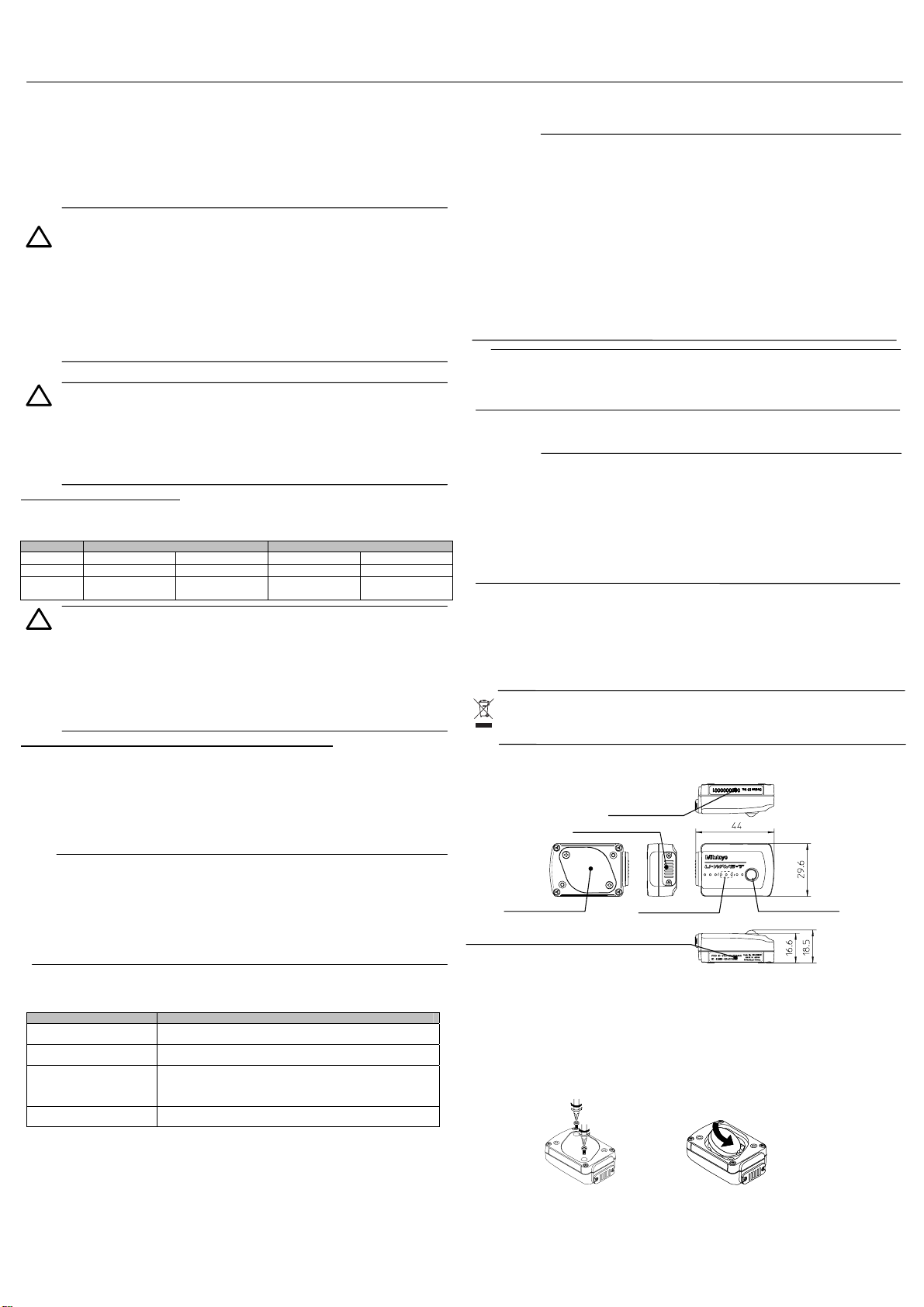
[1] Name of Each Part and External Dimensions (Unit : mm)
1. LED display (green, red, orange) 2. Battery cover 3. Connector cover
4. Device ID label 5. Buzzer holes (for th e buzzer type only) 6. Certificati on label
2. Battery cover
5. Certification label
(This label is different according to the country(region).)
[2] Replacing the Battery
1) Setting the battery
No battery has been set before shipping. After unpacking the U-WAVE-T, set the battery with the
following procedure. W hen screwing or unscrewing the screw s, always use the size 0 screwdriver (No.
05CZA619) of the st andard accessory and tig hten or loosen them wit h a torque of 5 to 8 N •cm.
(1) Remove the two mounting screws (M2.5X0.45X3/No. A115-2515C) with the size 0 screwdriver.
(2) Dismount the batt ery cover.
(3) Orientate the battery pl us side toward the cover, slide i ts one end into the “+” terminal on th e
U-WAVE-T, and then insert the other end into the battery ret aining claw.
(4) Check that the packing (No. 02AZD734) has been attached correctly to the specified position.
(5) Mount the battery cov er.
(6) Tighten the mounting scr ews with the size 0 screwdriver to fix th e cover.
(7) Make sure that no part of the packing is detached.
(1),(6) (3)
2) Removing the battery
To remove the battery, use a small flat-blade screwdriver, etc. Inse rt the screwdriver between the
battery retaining claw and th e battery, and then remove the bat tery by using the screwdrive r as
leverage.
4. Device ID label
3. Connector cover
6. Buzzer holes
(for the Buzzer type)
No.99MAL108B2
1. LED display
Page 3

3) Low battery alarm
If the battery voltage becomes considerably low, the LED display blinks red and the U-WAVE-T sends
a low battery alarm error to the U-WAVE-R. Immediately replace the battery.
(The buzzer type alarms a low bat tery voltage with a buzzer sound al ong with a blinking LED.)
IMPORTANT
•
Always use the CR2032 battery (lithium batter y).
• The battery supplied at the time of purchase is to check the functi ons and performance of the
U-WAVE-T. The predetermi ned length of life may not be met.
• Even for the used CR2032 batt ery, its voltage may recover in a sho rt time after it is removed from
the U-WAVE-T. However, do n ot continue to use the old battery. Be sur e to replace the battery
with a new one.
• Upon disposal of the battery comply with the related ordinance, regulation, etc.
• When removing or setting the battery, exercises car e so as not to break or bend the batt ery terminal
by applying an undue force to it.
[3] Connect the Connecting cable to U-WAVE-T
• After loaded with the battery, connect the connecting cable (option, details see section 8)
IMPORTANT
When installing the U -WAVE-T using the c onnecting cable (02A ZD791A, B), particularl y
pay attention to the cable orientation. If the cable is connected in the reverse orientation,
data cannot be transmitted.
Black-marked side => U-WAVE-T
Gray-marked side => Measuring tool
DATA switch
• Set up the connecting cable with the following procedure.
When screwing or unscrewing the scr ews, always use the size 0 screwdri ver of the
standard accessory and tight en or loosen them with a torque of 5 to 8 N• cm.
(1) Remove the two mounting screws (M1.7X0.35X2.5/No.A115-1712C) of the connector cover with
the size 0 screwdriver.
(2) Dismount the connect or cover.
(3) Check that the packing (No. 09GAA 374) has been attached correctl y to the specified position.
(4) Connect the connecti ng cable with the U-W AVE-T.
(5) While pressing the connecting ca ble end with fingers, tighten the cable fixing screws so that no gap
appears between the c able connector and the U-WAVE-T.
(6) Make sure that no part of the packi ng is detached.
(1) (5)
[4] Register the setting information of U-WAVE-R
After loaded with the battery and connected to a connecting cable, the U-WAVE-T needs to register the
setting information of U-WAVE-R.
Please read the “U-WAVEP AK User’s Manual“ in “PDF_Manual” folder of the CD supplied as a standard
accessory of U-WAV E-R for a detailed registeri ng method and content .
“Adobe Reader” of Adobe Systems INC. is necessary to read.
IMPORTANT
• “Registering the setting information” should be performed by DATA switch of the connecting
cable before connecting to the Measuring tool.
• The registered information is stored after changing battery.
[5] Connecting to Measuring tool
• After registering the setting information, connect the U-WAVE-T to the Measuring tool.
• Clamp the cable leading to a Measuring tool using th e supplied cable clamp or a Velcro f astener so
that measurement is not interfered and the LED display of the U-WAVE-T can be easily viewed.
[6] Functions
1) Data communication
The U-WAVE-T performs data communication with DATA switch as shown below.
Transmits measurement data. t ≤ 2sec None
Transmits the Cancel command. 2 sec < t ≤ 5 sec
Executes U-WAVE-R search. 5 sec < t ≤ 10 sec
NOTE
• The Cancel command is a command t o inform a U-WAVE-R of data error when wrong
measurement data is transmitted to the U-WAVE-R due to an operating error. However, the
wrong measurement data is not canceled by the command. It is to inform that the previous
data is different from measuring value.
• When the U-WAVE-R search is executed, U-WAVE-T is connected with U-WAVE-R that
can be registered.
• If the DATA switch is held down for more tha n 10 seconds, the orange LED stops blink ing
and nothing will function.
The U-WAVE-T can check whether to have performed normal com munication with a
U-WAVE-R by a specific LED display (and buzzer sound).
However, buzzer sounds are av ailable only for the buzzer type U-W AVE-T.
2) Initializing the setting information
IMPORTANT
Once initialization is perform ed, the setting information used u ntil then is all cleared.
Description of state LED Buzzer sound
Wireless communication has been
properly completed.
• Wireless communicatio n has failed.
• An error has occurred.
If communication is disabled while using the U-WAVE-T, firs t refer to Troubleshooting
In U-WAVE-R User’s Manual , if communication is still disabled, initialize the setting informati on
registered in section 4 to defa ult settings, and then retry com munication.
Initialize the setting informati on with the following procedure.
(1) Remove the battery being loaded. For information about how to remove the battery, refer to
section 2.
(2) While holding down the DATA switch on the connecting cable connector, reload the battery in
place. The setting informati on is initialized.
(3) Remount the batt ery cover, and set up the U-WAVE-T.
Black
Measuring tool side
U-WAVE-T side
Operations DATA switch push-down time t LED
(The connector shape and color differs depending on the
Measuring tool to be used. )
Green LED blinking Short 2 times
Red LED blinking Long 1 time
Orange blinking
0.1 sec interval
Orange blinking
0.3 sec interval
Mitutoyo Corporation
20-1, Sakado 1-Chome, Takatsu-ku, Kawasaki-shi, Kanagawa 213-8533, Japan
[7] Specifications
1) U-WAVE-T for Japan and EU (02AZD730A , 02AZD880A)
Country Japan, Europe
Model IP67 type Buzzer type
Code No. 02AZD730A 02AZD880A
Certification number 005NYCA0474(Japan) 005NYCA0476(Japan)
Protection class IP67 With/without buzzer Without With
Transmission output Less than 1 mW (0 dBm)
Distance of communication Approx. 20 m (line-of-sight di stance under office environm ents)
A Conformity standard
2) U-WAVE-T for U.S.A and Canada (02AZD730C , 02AZD880C)
Country U.S.A, Canada
Model IP67 type Buzzer type
Code No. 02AZD730C 02AZD880C
Certification number
Protection class IP67 With/without buzzer Without With
Transmission output Less than 0.5 mW (-3 dBm)
Distance of communication Approx. 14 m (line-of-sight di stance under office environm ents)
A Conformity standard
3) Common Specifications
Wireless communication pr otocol IEEE802.15.4 compatible
Wireless communication sp eed 250 Kbps
Operating temperature (h umidity) 0 to 40°C (20 to 80%RH, with no condensation)
Storage temperature (hum idity) -10 to 60°C (20 to 80%RH, with n o condensation)
4) Standard accessories
・User’s manual (this manual) No. 99MAL108B2 ・Size 0 screw driver No. 05CZA619
・Lithium battery CR20 32C(B)N ・Warranty card
5) Optional accessories No. 02AZD790A to G: Connecting ca bles (For details see section 8. )
[8] Connecting Cables
As for connecting cables, i t is necessary to selec t a cable compatible with a Measuring tool to be us ed.
Use an appropriate connecti ng cable from among those in the fol lowing table.
02AZD790A
Water-resistant type
with data out switch type
Color: Light gray
02AZD790B
Water-resistant type with
data out switch type
Color: Light gray
02AZD790C
With data out switch type
02AZD790D
10 pins type
02AZD790E
6 pins type
02AZD790F
A frat form straight type
Item Description
Communication frequenc y 2. 405 to 2.475 GHz
Used band 15 chan nels (at intervals of 5 MHz)
Modulation method DSSS (Direct Sequence Spread S pectrum)
LED display Green/orange/red: 3 discrete color display
Battery CR2032 (3V): 1 piece
Battery life 400,000 times
External dimensions 44 X 29.6 X 18.5 (mm)
U-WAVE-T mass Approx. 23 g
Parts No. Model Series No, Product Name
02AZD790G
Water-resistant type with
frat form straight type
ARIB STD-T66
Japan
Europe
EN 50371:2002
EN 300 440- 1 V1.3.1 and EN 300 440-2 V1.1.2
EN 301 489-01 V1.6.1 and EN 301 489-03 V1.4.1
VXU-02AZD730C (U.S.A)
4396B-02AZD730C (Ca nada)
・47 CFR Part 15.247:(Subpart :C) ・47 CFR Part 15,(Subpart :B)
U.S.A
・RSS-210 (Issue 7) and RSS-Gen (Issue 2) ・ ICES 003 (Issue 4)
Canada
500
ABS Coolant Pro of Caliper CD-PMX/PM/GM
500
Super Caliper C D-SPM
571
ABS Coolant Proof Depth Gage VDS-PMX
572
ABS Coolant Proof Digimatic Scale U nits SD-G
573
ABS Coolant Proof Exclusiv e Caliper NTD-P MX/PM
Coolant Proof Micrometer MDC-MJ/MJT
293
Coolant Proof Micromet er MDE-MJ
293
Coolant Proof Exclusive Micrometer (The end of the mark is –MJ)
--Depth Micrometer DMC-M
329
Coolant Proof Digimatic Micrometer Heads MHN-M/MJ/MJN
350
---
Digimatic Exclusive Micrometer (The end of the mark is –M/PM)
468
Digimatic Holtest HTD-R
ABS Digimatic Caliper CD-CX/C
500
ABS Digimatic Depth Gage VDS-/DCX/DC
571
ABS Digimatic Scale Units SD-D/SDV-D
572
ABS Digimatic Caliper CD-SC
573
---
ABS Digimatic Exclusive Caliper (The end of the mark is –CX/C)
178
Surftest SJ-201/301/401/402
179
Digi-Derm DGE
318
Litematic VL-A/AS/AH
515
CERA Height Master HMD-C
518
QM-Height QMH-S
519
Digital Mu-Checker M
542
Display Unit EB/EC-D/EF
543
Digimatic Indicator ID-H/ID-F
544
Laser Scan Micrometer LSM-9506
544
Laser Scan Micr ometer LSM-6200/6900
(It applies when using Digimati c Codeout unit.(02AGC840))
572
Difference/Sum Unit SD-U1
574
Heightmatic HDF
164
Digimatic Micrometer Heads MHD-M
227
Digimatic Micrometer Heads CLM-MH
227
Soft-Touch Micromet er CLM
293
Quickmike MDQ
293
Exclusive Quickmike (The end of the mark is –Q M)
Digimatic Micrometer MDC-M
---
Digimatic Exclusive Mic rometer (The end of the mar k i s -DM)
339
Digimatic Tubular Inside Microm eter IMJ-M
337
Digimatic Tubular Inside Micrometer IMZ-M
468
Digimatic Holtest HTD
515
Digital Height Master HME-DM
568
ABS Borematic SBM-C
810
Hardness Testing Machine HM-100/200/HV-100/HH-411
810
Rockwell Type Hardness Testing Machines HR-500
192
Digimatic Height Gage HDM-A/HD-A
500
Digimatic Caliper CD
511
ABS Digimatic Bore Gage CG-D
543
ABS Digimatic Indicator ID-S
543
ABS Digimatic Indicator ID-C
550
Digimatic Caliper CD
551
Digimatic Caliper CD
552
Digimatic Carbon Fiber Caliper CFC
570
ABS Digimatic Height Gage HDS-HC/C
547
ABS Digimatic Depth Gag e
572
ABS Digimatic Scale Units SD-E/SDV-E/SD-V/SDV-F
574
Heightmatic HDF-N
575
ABS Digimatic Indicator ID-U
811
Hardness Testing Units HH-300
543 ABS Digimatic Indicator ID-N/ID-B
VXU-02AZD880C (U.S.A)
4396B-02AZD880C (Ca nada)
KAWASAKI, JAPAN
 Loading...