

Page 1
A_ MITSUBISHI
THE BIG SCREEN COMPANY TM
Owner's Guide
Page 2
RISK OF ELECTRIC SHOCK
DO NOT OPEN
CAUTION: TO REDUCE THE RISK OF ELECTRIC SHOCK, DO NOT REMOVE COVER (OR
BACK). NO USER SERVICEABLE PARTS INSIDE. REFER SERVICING TO QUALIFIED
SERVICE PERSONNEL.
_k The lightning flash with arrowhead symbol within an equilateral triangle is intended to alert the user of
the presence of uninsulated "dangerous voltage" within the product's enclosure that may be sufficient
magnitude to constitute a risk of electric shock.
The exclamation point within an equilateral triangle is intended to alert the user to the presence of important
operating and maintenance (servicing) instructions in the literature accompanying the appliance.
Warning: To avoid permanently imprinting a fixed image onto your TV screen, please do not display the same
stationary images on the screen for more than 15% of your total TV viewing in one week. Examples of stationary
images are letterbox top/bottom bars from DVD disc or other video sources, side bars when showing standard TV
pictures on widescreen TVs, stock market reports, video game patterns, black or bright Closed Caption backgrounds,
station Iogos, web sites or stationary computer images. Such patterns can unevenly age the picture tubes causing
permanent damage to the TV. Please see pages 14 and 72 for a detailed explanation.
Note: This equipment has been tested and found to comply with the limits for a Class B digital device, pursuant to
part 15 of the FCC Rules. These limits are designed to provide reasonable protection against harmful interference in
a residential installation. This equipment generates, uses and can radiate radio frequency energy and, if not installed
and used in accordance with the instructions, may cause harmful interference to radio communications. However,
there is no guarantee that interference will not occur in a particular installation. If this equipment does cause harmful
interference to radio or television reception, which can be determined by turning the equipment off and on, the user is
encouraged to try to correct the interference by one or more of the following measures:
• Reorient or relocate the receiving antenna.
• Increase the separation between the equipment and the receiver.
• Connect the equipment into an outlet on a circuit different from that to which the receiver is connected.
• Consult the dealer or an experienced radio/TV technician for help.
Changes or modifications not expressly approved by Mitsubishi could void the user's authority to operate this
equipment.
WARNING: TO REDUCE THE RISK OF FIRE OR ELECTRIC SHOCK, DO NOT EXPOSE THIS APPLIANCE TO RAIN OR
MOISTURE.
CAUTION: TO PREVENT ELECTRIC SHOCK, MATCH WIDE BLADE OF PLUG TO WIDE SLOT, FULLY INSERT.
NOTE TO CATV SYSTEM INSTALLER: THIS REMINDER IS PROVIDED TO CALL THE CATV SYSTEM INSTALLER'S
ATTENTION TO ARTICLE 820-40 OF THE NEC THAT PROVIDES GUIDELINES FOR THE PROPER GROUNDING AND,
IN PARTICULAR, SPECIFIES THAT THE CABLE GROUND SHALL BE CONNECTED TO THE GROUNDING SYSTEM OF
THE BUILDING, AS CLOSE TO THE POINT OF CABLE ENTRY AS PRACTICAL.
This TV is very heavy! Exercise extreme care when moving TV as foreign material may become
embedded in the castor wheels which could damage wood or other delicate flooring.
Page 3
Contents
Chapter I Television Overview
Chapter 2 Connecting
Chapter 3 Basic Functions including NetCommand ® Setup and Editing
Thank You ........................................................................................................................................................ 8
Unpacking your New TV ................................................................................................................................... 9
Special Features ............................................................................................................................................... 9
Front Control Panel ......................................................................................................................................... 10
Back Panel ..................................................................................................................................................... 12
Important Notes .............................................................................................................................................. 14
External Devices and NetCommand Setup (Overview) ................................................................................. 16
NetCommand Pre-Memorized Devices ......................................................................................................... 17
Antenna or Wall Outlet Cable for Digital Broadcasts ..................................................................................... 18
Separate UHF and VHF Antennas for Analog Broadcasts ............................................................................ 18
Single Analog Antenna, Wall Outlet Cable ..................................................................................................... 19
Cable Box ........................................................................................................................................................ 19
Analog VCR ..................................................................................................................................................... 20
Analog VCR to a Cable Box ............................................................................................................................ 20
Analog VCR with Composite Video or S-Video and Audio Connections ...................................................... 21
Audio/Video Surround Sound Receiver or Stereo System ............................................................................ 21
DVD Player with Component Video ................................................................................................................ 22
Satellite Receiver with S-Video ....................................................................................................................... 22
External Digital TV (DTV or HDTV) Receiver ................................................................................................. 23
MonitorLink TM with MonitorLink Control or DVI .............................................................................................. 25
Computer with a VGA Monitor ........................................................................................................................ 25
IR Emitter NetCommand® or IR Emitter Repeater ........................................................................................ 25
Remote Control Functions: Overview ............................................................................................................. 28
Remote Control Functions: Operation and Care............................................................................................ 29
Programming the Remote Control to Control NetCommand A!V Products ................................................. 30
3D Graphical Viewpoint Menu System ........................................................................................................... 31
Using the Remote Control with NetCommand@ Setup ................................................................................. 32
NetCommand Initial Setup Guide ................................................................................................................... 33
NetCommand Editing Guide ........................................................................................................................... 34
NetCommand Initial Setup .............................................................................................................................. 35
Edit NetCommand ......................................................................................................................................... 37
Connecting IEEE 1394 Devices ...................................................................................................................... 45
Adding IEEE 1394 Devices Automatically ...................................................................................................... 47
Chapter 4 Device Selection
Device Selection Menu ................................................................................................................................... 50
PiP Device Selection Menu ............................................................................................................................. 51
Transport Menu ............................................................................................................................................... 51
Channel Selection, Sleep Timer, Audio and Video Buttons ........................................................................... 52
NetCommand Controlled Recordings ............................................................................................................ 53
Chapter 5 TV Menu Screen Operations
Chapter 6 Special Features
Main Menu Choices ........................................................................................................................................ 56
Setup Menu ..................................................................................................................................................... 57
Antenna Menu ................................................................................................................................................. 58
Time Menu ....................................................................................................................................................... 60
Captions Menu ................................................................................................................................................ 62
V-Chip Lock Menu .......................................................................................................................................... 64
A/V Settings Menu .......................................................................................................................................... 67
A/V Settings Descriptions .............................................................................................................................. 68
Advanced Menu: Reset Factory Defaults, Convergence .............................................................................. 70
Important Notes .............................................................................................................................................. 72
NetCommand Controlled Peer-to-Peer Connections .................................................................................... 74
NetCommand Remote Control Buttons: Device Menu, Guide ...................................................................... 75
Recording on a Net Command® Traditional VCR, A/V Disc Search, Track List Screen .............................. 76
Memory Card Playback .................................................................................................................................. 77
Device Menu with NetCommand .................................................................................................................... 79
Operation of PIP and POP .............................................................................................................................. 81
Display Formats ............................................................................................................................................. 82
Software Updates ........................................................................................................................................... 84
Appendixes ..................................................................................................................................................... 85
Troubleshooting .............................................................................................................................................. 100
Index ................................................................................................................................................................ 104
Warranty ......................................................................................................................................................... 107
Page 4
IMPORTANT SAFEGUARDS
Please read the following safeguards for your TV and retain for future reference. Always follow all
warnings and instructions marked on the television.
1. Read, Retain and Follow All Instructions
Read all safety and operating instructions before operating the "IV. Retain the safety and operating instructions
for future reference. Follow all operating and use instructions.
2. Heed Warnings
Adhere to all warnings on the appliance and in the operating instructions.
3. Cleaning
Unplug the TV from the wall outlet before cleaning. Do not use liquid, abrasive, or aerosol cleaners. Cleaners
can permanently damage the cabinet and screen. Use a lightly dampened cloth for cleaning.
4. Attachments and Equipment
Never add any attachments and/or equipment without approval of the manufacturer as such additions may result
in the risk of fire, electric shock or other personal injury.
5. Water and Moisture
Do not use the "IV where contact with or immersion in water is possible. Do not use near bath tubs, wash bowls,
kitchen sinks, laundry tubs, swimming pools, etc.
6. Accessories
Do not place the TV on an unstable cart, stand, tripod, or table. The TV may fall, causing seri-
ous injury to a child or adult and serious damage to the "IV. Use only with a cart, stand, tripod,
bracket, or table recommended by the manufacturer, or sold with the TV. Any mounting of
the TV should follow the manufacturer's instructions, and should use mounting accessories
recommended by the manufacturer.
An appliance and cart combination should be moved with care. Quick stops, excessive force,
and uneven surfaces may cause the appliance and cart combination to overturn.
7. Ventilation
Slots and openings in the cabinet are provided for ventilation and to ensure reliable operation of the "IV and to
protect it from overheating. Do not block these openings or allow them to be obstructed by placing the TV on a
bed, sofa, rug, or other similar surface. Nor should it be placed over a radiator or heat register. If the TV is to be
placed in a rack or bookcase, ensure that there is adequate ventilation and that the manufacturer's instructions
have been adhered to.
8. Power Source
This IV should be operated only from the type of power source indicated on the marking label. If you are not sure
of the type of power supplied to your home, consult your appliance dealer or local power company.
9. Grounding or Polarization
This IV is equipped with a polarized alternating current line plug having one blade wider than the other. This plug
will fit into the power outlet only one way. If you are unable to insert the plug fully into the outlet, try reversing the
plug. If the plug should still fail to fit, contact your electrician to replace your obsolete outlet. Do not defeat the
safety purpose of the polarized plug.
10. Power-Cord Protection
Power-supply cords should be routed so that they are not likely to be walked on or pinched by items placed
upon or against them, paying particular attention to cords at plugs, convenience receptacles, and the point
where they exit from the TV.
11. Lightning
For added protection for this "IV during a lightning storm, or when it is left unattended and unused for long
period of time, unplug it from the wall outlet and disconnect the antenna or cable system. This will prevent
damage to the "IV due to lightning and power-line surges.
4
Page 5
IMPORTANT SAFEGUARDS, cont'd.
12. Power Lines
An outside antenna system should not be located in the vicinity of overhead power lines or other electric light or
power circuits, or where it can fall into such power lines or circuits. When installing an outside antenna system,
extreme care should be taken to keep from touching such power lines or circuits as contact with them might be
fatal.
13. Overloading
Do not overload wall outlets and extension cords as this can result in a risk of fire or electric shock.
14. Object and Liquid Entry
Never push objects of any kind into this -IV through openings as they may touch dangerous voltage points or
short-out parts that could result in fire or electric shock. Never spill liquid of any kind on or into the TV.
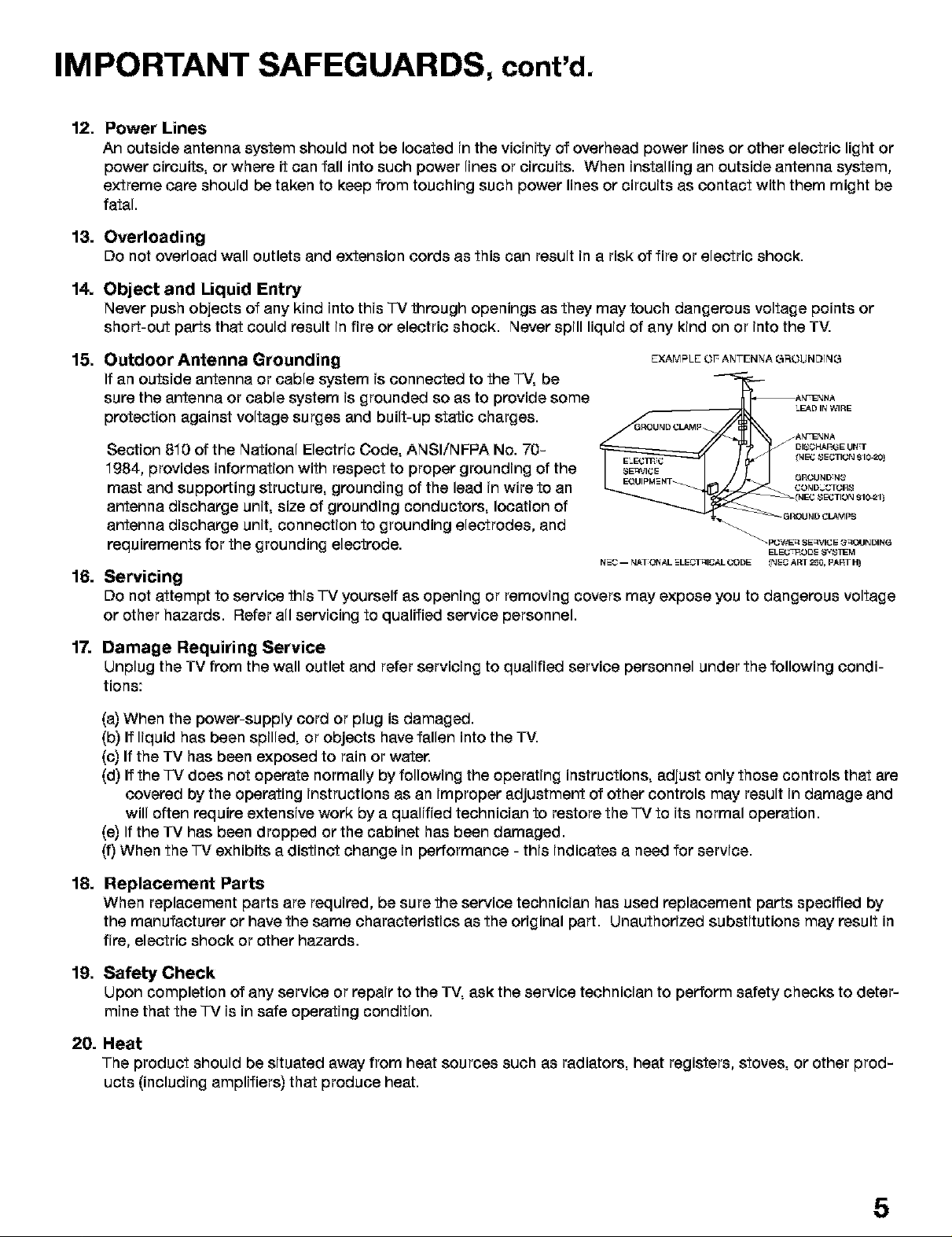
15. Outdoor Antenna Grounding
EXAMPLE OF ANTENNA GROUNDING
If an outside antenna or cable system is connected to the "I-V,be
sure the antenna or cable system is grounded so as to provide some
protection against voltage surges and built-up static charges.
Section 810 of the National Electric Code, ANSI/NFPA No. 70-
_'_ _At, NENNA
GROUNDGL.e,J_p
LEAD IN WIRE
At,£qENNA
I_1E42SECTION 910-20)
1984, provides information with respect to proper grounding of the
mast and supporting structure, grounding of the lead in wire to an
_20_1D_C3 OR8
antenna discharge unit, size of grounding conductors, location of
antenna discharge unit, connection to grounding electrodes, and
requirements for the grounding electrode.
N2-C-- tt&TONAL _LECTqlCAL CODE INEC Am 2_0, P&PT _
_ P_WEq SE_',_I_2E G_tlNDING
16. Servicing
Do not attempt to service this TV yourself as opening or removing covers may expose you to dangerous voltage
or other hazards. Refer all servicing to qualified service personnel.
17. Damage Requiring Service
Unplug the TV from the wall outlet and refer servicing to qualified service personnel under the following condi-
tions:
(a) When the power-supply cord or plug is damaged.
(b) If liquid has been spilled, or objects have fallen into the TV.
(c) If the TV has been exposed to rain or water.
(d) If the "IV does not operate normally by following the operating instructions, adjust only those controls that are
covered by the operating instructions as an improper adjustment of other controls may result in damage and
will often require extensive work by a qualified technician to restore the TV to its normal operation.
(e) If the TV has been dropped or the cabinet has been damaged.
(f) When the "IV exhibits a distinct change in performance - this indicates a need for service.
18. Replacement Parts
When replacement parts are required, be sure the service technician has used replacement parts specified by
the manufacturer or have the same characteristics as the original part. Unauthorized substitutions may result in
fire, electric shock or other hazards.
19. Safety Check
Upon completion of any service or repair to the TV, ask the service technician to perform safety checks to deter-
mine that the TV is in safe operating condition.
20. Heat
The product should be situated away from heat sources such as radiators, heat registers, stoves, or other prod-
ucts (including amplifiers) that produce heat.
5
Page 6

6
Page 7
Page 8
Our Thanks...
Thank you for choosing Mitsubishi as your premier Home Entertainment provider.
This Owner's Guide describes the features and functions of your Mitsubishi
widescreen, high definition TV. We urge you to examine this Owner's Guide to
become familiar with the innovative features and operations this unique television
offers.
The very core of our corporate philosophy is to provide our customers with the
very best. Our development team at Mitsubishi has worked to provide you with a
television that defines "state-of-the-art," with the capability to meet your needs now
and in the future.
Whether this is your first Mitsubishi electronic product, or an addition to your
Mitsubishi collection, we believe you and your family will continue to enjoy your
Mitsubishi home theater for many years.
Thank you,
Mitsubishi Digital Electronics America, Inc.
8
Page 9

Unpacking Your New TV
Special Features
Please take a moment to review the following
list of items to ensure that you have received
everything including:
1. Remote Control
2. (Two)AA Batteries
3. (One) Digital Audio Cable
Your new High Definition bigscreen television has
many special features that make it the perfect
center of your home entertainment system.
These special features include:
Fully Integrated HDTV
Your Mitsubishi bigscreen TV can receive all approved
terrestrial broadcast digital signals, non-scrambled
digital cable signals, terrestrial analog signals and non-
scrambled analog cable signals that use a standard
offset carrier system. Further, your -IV will display all High
Definition signals as 1380i True HDTV rMand all standard
definition signals will be displayed as 480p.
NetCommand ® Home Network Control
System
Your Mitsubishi bigscreen HDTV offers a new level of
networking to combine selected older products with
new and future digital products. NetCommand supports
IEEE 1394 connections, HAVi (Home Audio Video
Interoperability) Control system, Audio Video Control
system (AV/C), 5C copy protection and IR control of
selected older products such as VCRs, DVD players,
cable boxes or satellite receivers. NetCommand includes
the ability to learn remote control signals directly
from many devices, allowing you to customize the
NetCommand system in a way that works best for your
viewing.
4. (One) Double fR Emitter Cable
5. (One) Quadruple fR Emitter Cable
6. Product Registration Card (not pictured)
Z Owner's Guide (notpictured)
8. Quick Reference Card (not pictured)
Wide Screen Picture Format
Enjoy a full theatrical experience inthe comfort of your
home. View pictures as film directors intended them.
Both digital -IV broadcasts and DVDs support the
widescreen format well-suited for your new TV.
PIP/POP Viewing Option
Using Picture-in-Picture and Picture-outside-Picture
will give you exciting options for viewing your favorite
programs.
V-Chip Technology
Your Mitsubishi bigscreen will allow you to restrict viewing
of programming by general content, category contents, or
even by time.
Memory Card
You can display a slideshow of your favorite JPEG pictures
or listen to Audio selections that have been recorded on
compatible Memory Cards.
9
Page 10
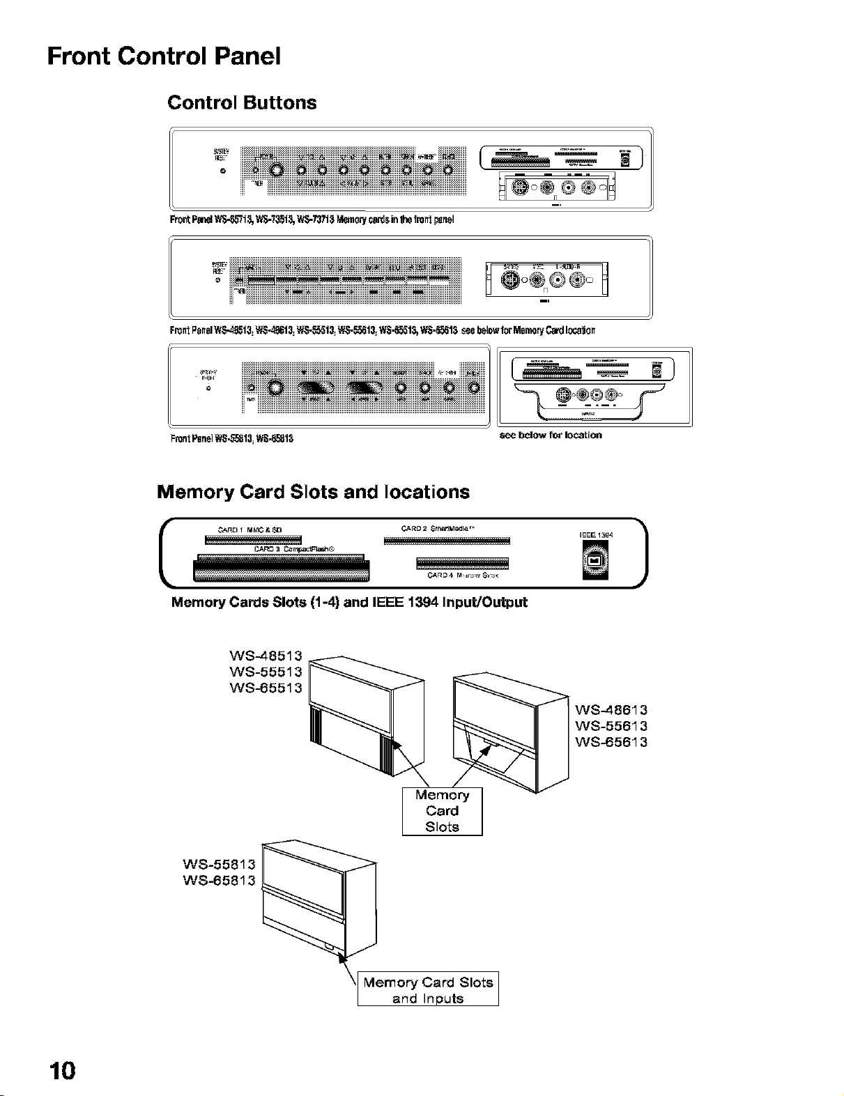
Front Control Panel
Control Buttons
o iiiiii@iiiii@iiii@iiiii@iiii@iiiii@iiii@iiiii@iiii@iiiiii
......_iiiiiiiiiiiiii_iiiiiii_!!!!!_!!!!!!_!!!_!!!!!!!!!!!!!!!
FrontF_ WS-_I_, 'A_-7_1_,t_TJ718 _o_ ca_sin_ front_nel
o iii_i) iiiii) 0 0
ii__ iiiiiiiiiiiiiiiiiii_i_i_iiiiiiii_i_ii))iiiiiii_iiiiiii_iiiii_iiiiiiiiiiiiiiiiiii
FrontI_nelW_hgSl3=WS._I 3=WS-._13=WS-55513=WS-55513,WS-55513seebelcw1orMemoryC_ local)on
o
_roniP_n_lWS-55813_W_-55813
H
_ '_)
Memory Card Slots and locations
L3A_C 3 _rnpactFla_ ®
Memory Cards Slots (1-4) and IEEE 1394 Input/Output
WS-48513
WS-55513
WS-65513
Memory
Card
Slots
W8-55813
WS-65813
WS-48613
WS-55613
WS-65613
10
Memory Card Slots
and Inputs
Page 11
Front Control Panel
The buttons (previous page) on the Front Control Panel highlighted fn gray are duplicated on the remote control. The
top row of labels show the control functions when there are no TV menus displayed on the screen. The bottom row of
labels show the control functions when the TV menus are displayed on the screen or when a special function has been
activated. See Remote Control Overview page 28, for further details on the functions of these buttons.
System Reset
If the TV will not respond to either the remote control or the front panel controls and wfll not power off_ press the
SYSTEM RESET button with a pointed item like the end point of a paperolfp. The TV will turn Off and the TIMER light
will flash quickly for about one minute. When the TIMER light stops flashing, you may turn on the TV again. The
changes you made while the "IV was On before you used the SYSTEM RESET button may be lost, however, the
changes you made previously are not lost.
Power/Timer Indicator
The green Ifght is a multi-functfon indfcator. Each time the TV fs plugged into the wall electrfcal outlet_ when power fs
restored after a power failure, after powering On from the Low Energy Mode, or using the SYSTEM RESET button, this
light wfll flash rapfdly for about one minute. Do not attempt to turn on the TV durfng thfs period. Waft for the flashing to
stop before attemptfng to turn the TV on. While the "IV is powered on, the Ifght illumfnates steadily. If the TV has been
programmed to turn on automatfcally using the Timer feature, this light wfll flash slowly while the TV is powered off.
A/V Reset
Press this button to reset all A/V memories to the factory default settfngs.
Input 3
This input can be used for convenient connectfon of a camcorder or other video devfce to the TV. If you connect
to the S-VIDEO terminal, the VIDEO termfnal fs deactfvated. The VIDEO terminal is active when there is no S-Vfdeo
connectfon.
Memory Card Slots (1-4) and IEEE 1394 Input/Output
There are four card slots behind the front panel of the "IV that allow the playback of JPEG pfctures from many dfgftal
cameras, MP3 or WMA audio files recorded from computers or other digital recording devices.
The card slots are designed for specific types of cards and other cards or objects should not be inserted into the
slots as thfs may damage the TV. CARD 1 slot is for both MultiMedfaCard rM(MMC) and Secure Dfgftal (SD) cards.
CARD 2 slot is for SmartMedia ]r'_cards. CARD 3 slot fsfor CompactFlash® cards and CARD 4 is compatfble wfth
MEMORYSTIcK]r`_cards. See Memory Card (slideshow, playlist) setup, page 77 for detafls about JPEG, MP3 and WMA7
file types that are compatfble wfth the TV.
The IEEE 1394 input/output allows for temporaryconnectfon of IEEE 1394 devices such as some camcorders, to the
front of the TV. This connection works the same way as the two rear IEEE 1394 connections.
11
Page 12
Back Panel
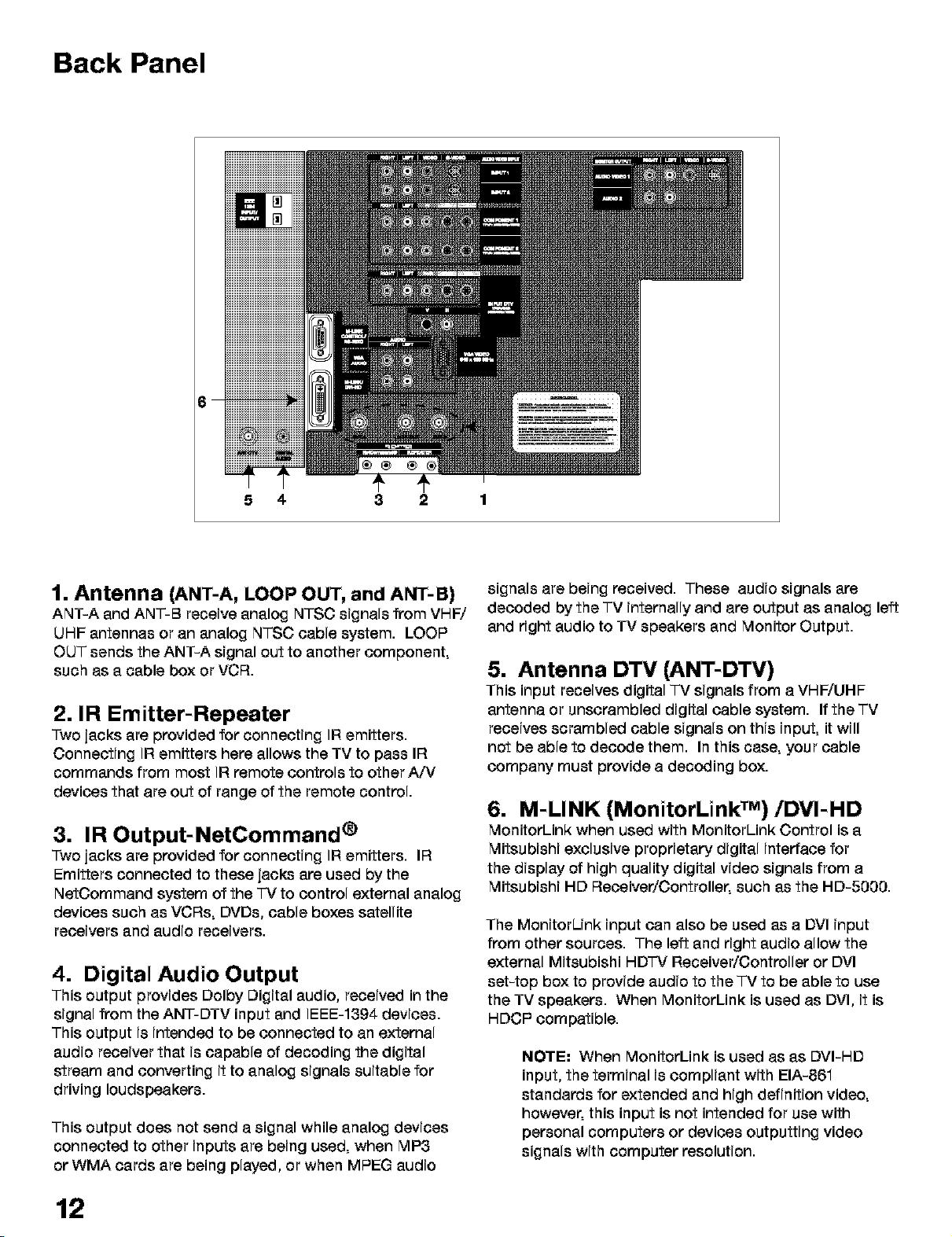
5 4 3 2 1
1. Antenna (ANT-A, LOOP OUT, and ANT-B)
ANT-A and ANT-B receive analog NTSC signals from VHW
UHF antennas or an analog NTSC cable system. LOOP
OUT sends the ANT-A signal out to another component,
such as a cable box or VCR.
2. IR Emitter-Repeater
Two jacks are provided for connecting IR emitters.
Connecting IR emitters here allows the TV to pass IR
commands from most IF{remote controls to other A/V
devices that are out of range of the remote control.
3. IR Output-NetCommand ®
Two jacks are provided for connecting IR emitters. IR
Emitters connected to these jacks are used by the
NetOommand system of the "IV to control external analog
devices such as VCRs, DVDs, cable boxes satellite
receivers and audio receivers.
4. Digital Audio Output
This output provides Dolby Digital audio, received in the
signal from the ANT-DTV input and IEEE-1394 devices.
This output is intended to be connected to an external
audio receiver that is capable of decoding the digital
stream and converting it to analog signals suitable for
driving loudspeakers.
This output does not send a signal while analog devices
connected to other inputs are being used, when MP3
or WMA cards are being played, or when MPEG audio
signals are being received. These audio signals are
decoded by the TV internally and are output as analog left
and right audio to TV speakers and Monitor Output.
5. Antenna DTV (ANT-DTV)
This input receives digital TV signals from a VHF/UHF
antenna or unscrambled digital cable system. If the TV
receives scrambled cable signals on this input, it will
not be able to decode them. In this case, your cable
company must provide a decoding box.
6. M-LINK (MonitorLink TM)/DVI-HD
MonitorLink when used with MonitorLink Control is a
Mitsubishi exclusive proprietary digital interface for
the display of high quality digital video signals from a
Mitsubishi HD Receiver/Controller, such as the HD-5000.
The MonitorUnk input can also be used as a DVI input
from other sources. The left and right audio allow the
external Mitsubishi HD']-V Receiver/Controller or DVI
set-top box to provide audio to the TV to be able to use
the TV speakers. When MonitorLink is used as DVl, it is
HDCP compatible.
NOTE: When MonitorLink is used as as DVI-HD
input, the terminal is compliant with EIA-861
standards for extended and high definition video,
however, this input is not intended for use with
personal computers or devices outputting video
signals with computer resolution.
12
Page 13
Back Panel
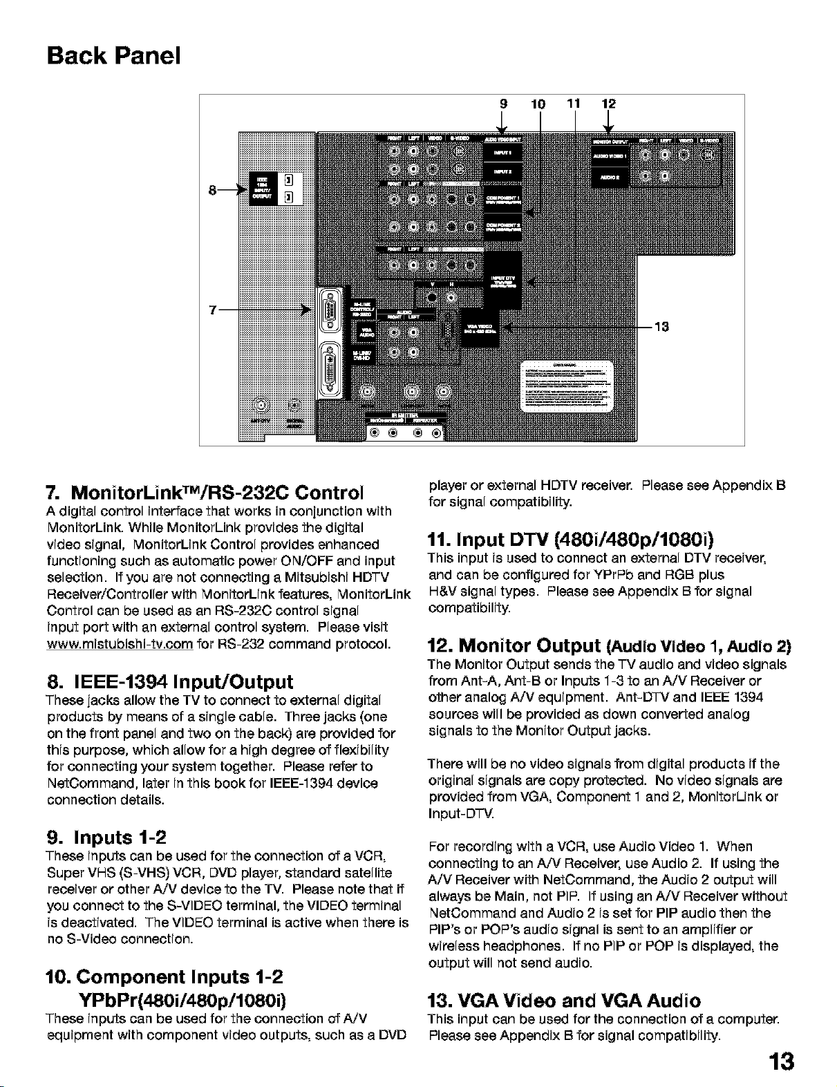
9 10 11 12
® ® ®
7. MonitorLinkTM/RS-232C Control
A digital control interface that works in conjunction with
MonitorLink. While MonitorLink provides the digital
video signal, MonitorLink Control provides enhanced
functioning such as automatic power ON/OFF and input
selection. If you are not connecting a Mitsubishi HD']'V
Receiver/Controller with MonitorLink features, MonitorLink
Control can be used as an RS-232C control signal
input port with an external control system. Please visit
www.mistubishi-tv.com for RS-232 command protocol.
8. IEEE-1394 Input/Output
These jacks allow the TV to connect to external digital
products by means of a single cable. Three jacks (one
on the front panel and two on the back) are provided for
this purpose, which allow for a high degree of flexibility
for connecting your system together. Please refer to
NetOommand, later in this book for IEEE-1394 device
connection details.
9. Inputs 1-2
These inputs can be used for the connection of a VCR,
Super VHS (S-VHS) VCR, DVD player, standard satellite
receiver or other A,_ device to the TV. Please note that if
you connect to the S-VIDEO terminal, the VIDEO terminal
is deactivated. The VIDEO terminal is active when there is
no S-Video connection.
10. Component Inputs 1-2
YPbPr(480i/480p/1080i)
These inputs can be used for the connection of A/V
equipment with component video outputs, such as a DVD
player or external HDTV receiver. Please see Appendix B
for signal compatibility.
11. Input DTV (480i/480p/1080i)
This input is used to connect an external DTV receiver,
and can be configured for YPrPb and RGB plus
H&V signal types. Please see Appendix B for signal
compatibility.
12. Monitor Output (Audio Video 1, Audio 2)
The Monitor Output sends the TV audio and video signals
from Ant-A, Ant-B or Inputs 1-3 to an A/V Receiver or
other analog A/V equipment. Ant-D'I-V and IEEE 1394
sources will be provided as down converted analog
signals to the Monitor Output jacks.
There will be no video signals from digital products if the
original signals are copy protected. No video signals are
provided from VGA, Component 1 and 2, MonitorUnk or
Input-D'l-V.
For recording with a VCR, use Audio Video 1. When
connecting to an A,_ Receiver, use Audio 2. If using the
A/V Receiver with NetOommand, the Audio 2 output will
always be Main, not PIP. If using an A/V Receiver without
NetCommand and Audio 2 is set for PIP audio then the
PIP's or POP's audio signal is sent to an amplifier or
wireless headphones. If no PIP or POP is displayed, the
output will not send audio.
13. VGA Video and VGA Audio
This input can be used for the connection of a computer.
Please see Appendix Bfor signal compatibility.
13
Page 14
IMPORTANT NOTES
Warning: Do not leave stationary PIP/POP, or letterbox images on the screen
for extended periods of time. Mix the types of pictures shown.
Uneven picture tube aging is NOT covered by your warranty.
The normal use of a "]-Vshould include a mixture of "]-V
picture types. The most frequently used picture types
should fill the screen with constantly moving images
rather than stationary images or patterns. Displaying the
same stationary patterns over extended periods of time
or displaying the same stationary pattern frequently can
leave subtle but permanent ghost images. To avoid this,
mix your viewing patterns. Reducing the initial contrast
level can help slow the aging process. Do not show
the same stationary image for more than 15% of your
total TV viewing in any given week. Display constantly
moving and changing images that fill the screen whenever
possible.
This projection TV uses picture tubes to project the image
to the screen. All picture tubes age with use. As they
age, their light output is gradually reduced. Normal TV
pictures fill the screen with constantly changing images.
Under these conditions, picture tubes age at an even
rate across the entire screen. This maintains a TV picture
that is evenly bright over the whole screen. Stationary
images or images that only partially fill the screen Cleaving
black or colored bars to fill the screen), when used over
extended periods of time or when viewed repeatedly, can
cause uneven aging of the phosphors and leave subtle
ghosts from the stationary images in the picture.
Examples of these types of images can be, but
are not limited to the following:
_.. Letterboxtop/bottom black bars:
shown at the top and bottom of the TV screen when you
watch a widescreen (16:9) movie on a standard (4:3) TV.
Side bar images:
solid bars shown on each side of an image when
watching a standard (4:3) program on a widescreen
(16:9) TV.
News and stock-market report bars:
ticker running at the bottom of the TV screen.
Shopping channel Iogos & pricing displays:
bright graphics that are shown constantly or repeatedly in
the same location.
Still or stationary images may be received from
broadcasters, cable channels, satellite channels, DVD
discs, video tapes, laser discs, on-line services, web/
Internet searching devices, video games, and digital TV
tuner/converter boxes.
When using a computer or similar device through a VGA
input, be sure to turn on the Screen Saver feature and set
the activation time to 5 minutes or less. If your computer
program allows, you should also set your toolbars to the
hidden mode.
14
Video game patterns and scoreboards
Bright station Iogos:
moving or low-contrast graphics are less likely to cause
uneven aging of the picture tubes.
Online (Internet) websites:
or any other stationary or repetitive computer style
images, including digital photos.
Closed Captioning
Mitsubishi recommends using a gray background rather
than black or a bright color if you frequently use closed
captioning.
Page 15
Page 16
Connecting External Devices & NetCommand® Setup
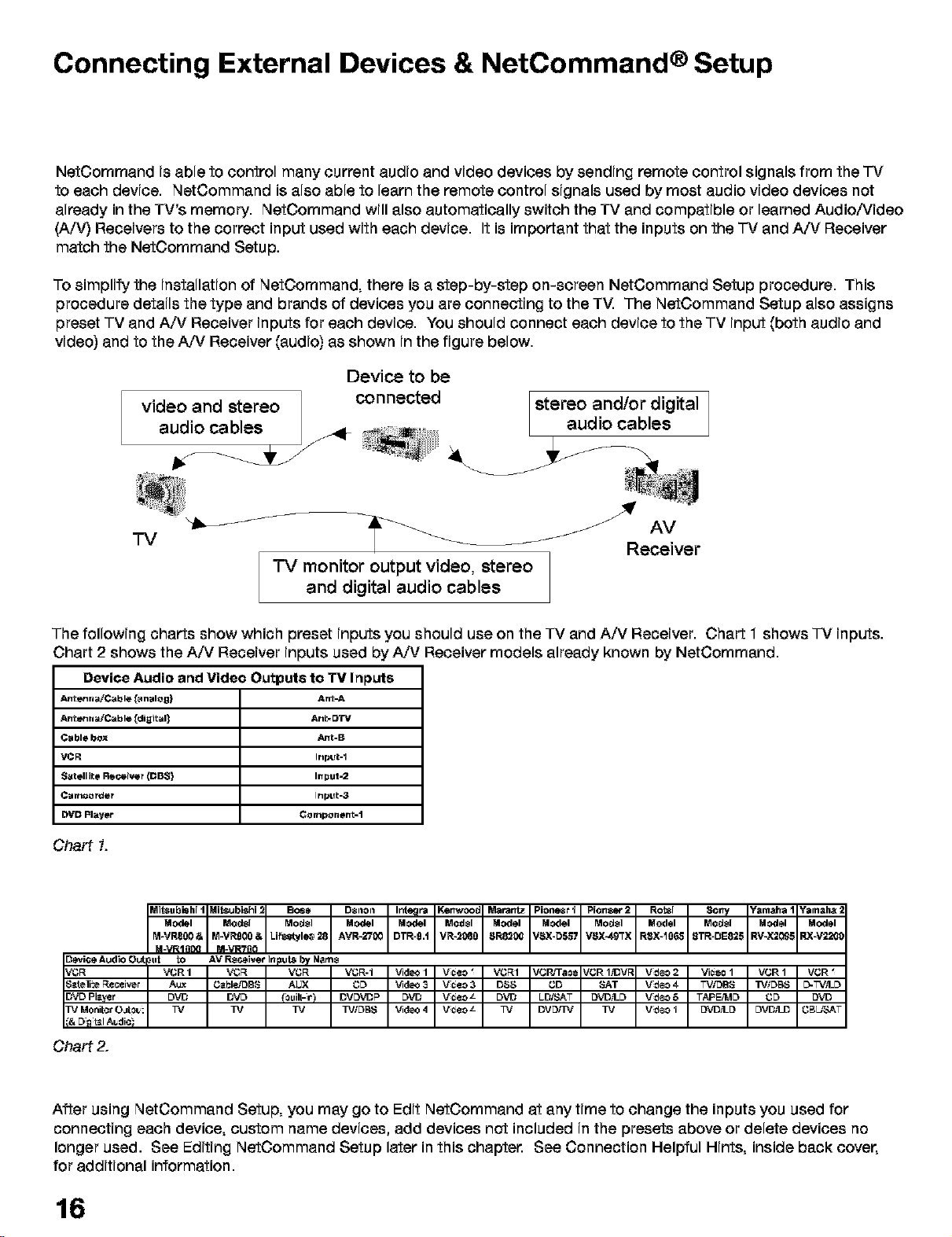
NetOommand is able to control many current audio and video devices by sending remote control signals from the "IV
to each device. NetCommand is also able to learn the remote control signals used by most audio video devices not
already in the TV's memory. NetOommand will also automatically switch the TV and compatible or learned Audio/Video
(A/V) Receivers to the correct input used with each device. It is important that the inputs on the "IV and A/V Receiver
match the NetOommand Setup.
To simpfify the installation of NetOommand, there is a step-by-step on-screen NetCommand Setup procedure. This
procedure details the type and brands of devices you are connecting to the TV. The NetOommand Setup also assigns
preset TV and AN Receiver inputs for each device. You should connect each device to the TV input (both audio and
video) and to the AN Receiver (audio) as shown in the figure below.
Device to be
video and stereo ]
audio cables
connected
/
stereo and/or digital
audio cables
"IV
"IV monitor output video, stereo
and digital audio cables
The following charts show which preset inputs you should use on the TV and A/V Receiver. Chart 1 shows "IV inputs.
Chart 2 shows the A/V Receiver inputs used by AN Receiver models already known by NetCommand.
Device Audio and Video Outputs to TV Inputs
Antenna/Cable [_nalog) Ar_-A
Antenna/Cable [digital] Ant= DW
Cable bOX ,&nt-B
VCR Input-I
Satellite Receiver (DBS) Input=2
Can1_order Input-3
DVD Player Component=1
Chart 1.
MO_I ModsI ModsI MO_I MO_I ModsI Model Model ModsI Model ModsI Model Model
M-VRS00& M-VRg00 & Lif_style_ 28 AVR-2700 DTR-9,t VR-2080 _R82,0_ VSX-D_7 V_X-49TX RSX-106,8 STR-DE825 RV-X209_ RX-V22C_
3_vice Audio Out
$_teli:e Receiver
3VD Player
B] Monitor0_o_:
M_VRIn0Q M-VR?n0
_ut _ AV _iver InFu_ by M_8
VCR I Vt3F_ Vt3F_ Vt3F_-I _d_ I V_¢eo_ Vt3F%I VCWTaOe JCR 1_V1_ V_deo2 Viceo 1 VCR 1 VGR
A_ G_bI_'DBS AUX t3D _d_3 V_¢eo3 D_S GD SAT V_deo4 TVIDBS TV/DBS D-TV,_D
DVD DVD {0uilt-_r) DVDVDP DVD V_¢eo_ DVD LD,%'AT DVD_I_D V_deo5 TAPE#_ID t3D DVD
TV TV TV TV/DBS _d_ 4 V_¢eo_ TV DV[_'IV TV V_deoI DVD_I_D DVDILD t3Bb_AT
Chart 2.
After using NetCommand Setup, you may go to Edit NetOommand at any time to change the inputs you used for
connecting each device, custom name devices, add devices not included in the presets above or delete devices no
longer used. See Editing NetOommand Setup later in this chapter. See Connection Helpful Hints, inside back cover,
for additional information.
16
Page 17
NetCommand ® Pre-Memorized Devices
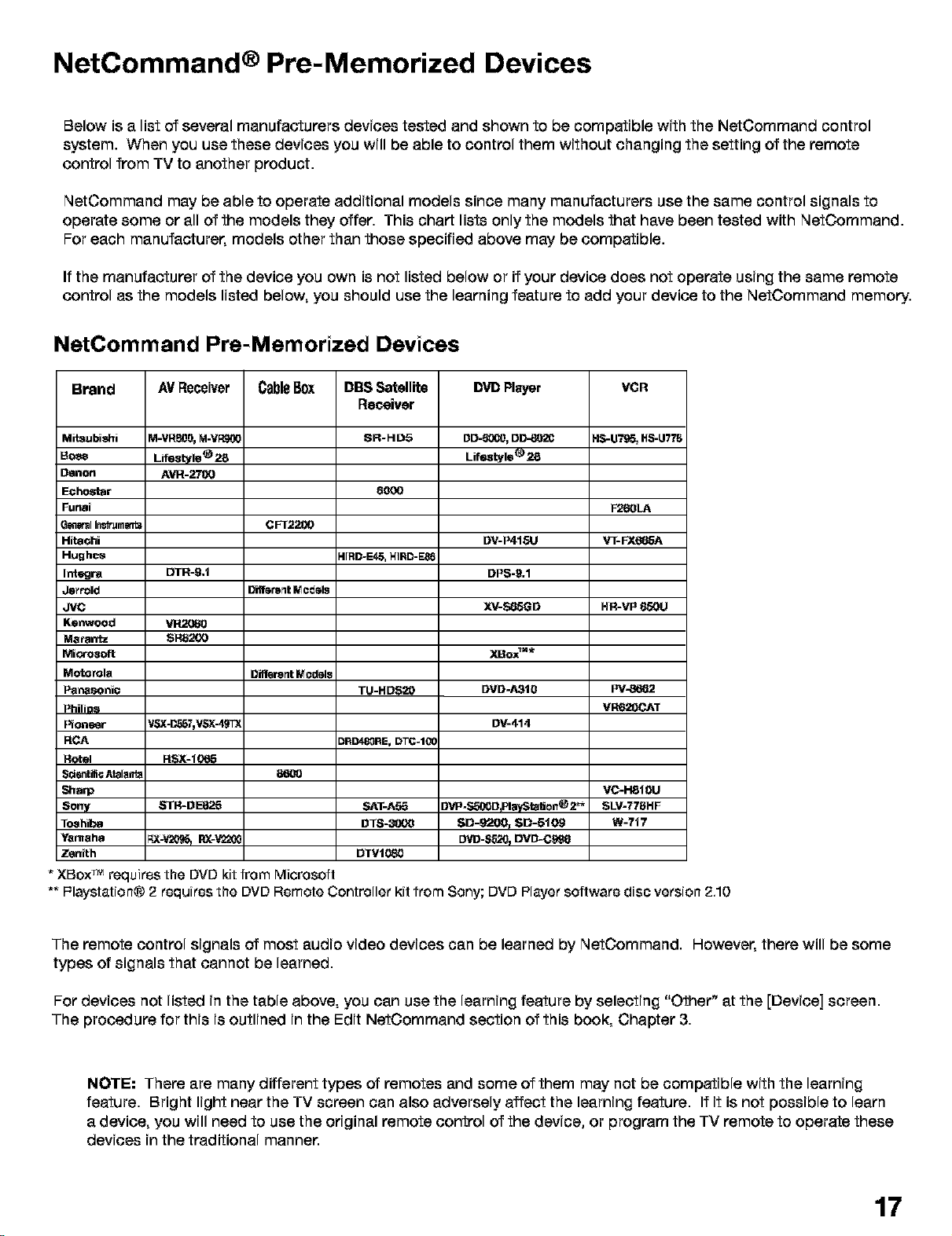
Below is a list of several manufacturers devices tested and shown to be compatible with the NetCommand control
system. When you use these devices you will be able to control them without changing the setting of the remote
control from TV to another product.
NetCommand may be able to operate additional models since many manufacturers use the same control signals to
operate some or all of the models they offer. This chart lists only the models that have been tested with NetCommand.
For each manufacturer, models other than those specified above may be compatible.
If the manufacturer of the device you own isnot listed below or if your device does not operate using the same remote
control as the models listed below, you should use the learning feature to add your device to the NetCommand memory.
NetCommand Pre-Memorized Devices
Brand
AVReceiver
CableBox
DBS Satellite
DVD Player
Receiver
Mitsubishi
Boe_
Oenon
Echostar
Funai
G_I In_+umtmt_
Hitaohi
Hughes
Integra
Jsrrold
JVC
Kenwoocl
Matantz
Mi_-osoft
Motorola
Panasoni¢
PhiliD_
I_on_tJr
RCA
Rotel
Scsntifi_ Atalar_
_arp
Sony
T_shil_a
Yamaha
Zenith
M-VRB0O,M-V_
Lif_le® _
A_-_
CFT2200
DTR-9,1
Different Models
vn2oe0
SR8200
Different Models
86_
STR-DE825
* XBoxTM requires the DVD kit from Microsoft
** F=laystation® 2 requires the DVD Remote Controller kit from Sony; DVD Player software disc version 2,10
SR-HD5
6000
41RD-E4_, HIFID-E_
SAT-AS5
OTS-_t)l)O
DTVIO80
DD-_, DD_02O
Lif_tyle_ _
DV-P415U
DPS-9.1
XV-S85GD
XBox_"*
DVD-A31e
DV-414
evP-Sro00OplayStaUon®2_
SD-9200_ SD=5109
DVD-SBL_pDVD-Cg_
HR-VP 650U
Pv-_
VRB20(_J_T
VC-H81OU
SLV-778HF
W-717
The remote control signals of most audio video devices can be learned by NetCommand. However, there will be some
types of signals that cannot be learned.
For devices not listed in the table above, you can use the learning feature by selecting "Other" at the [Device] screen.
The procedure for this is outlined in the Edit NetCommand section of this book, Chapter 3.
NOTE: There are many different types of remotes and some of them may not be compatible with the learning
feature. Bright light near the TV screen can also adversely affect the learning feature. If it is not possible to learn
a device, you will need to use the original remote control of the device, or program the TV remote to operate these
devices in the traditional manner.
17
Page 18
Connecting Antenna or Wall Outlet Cable for Digital Broadcasts
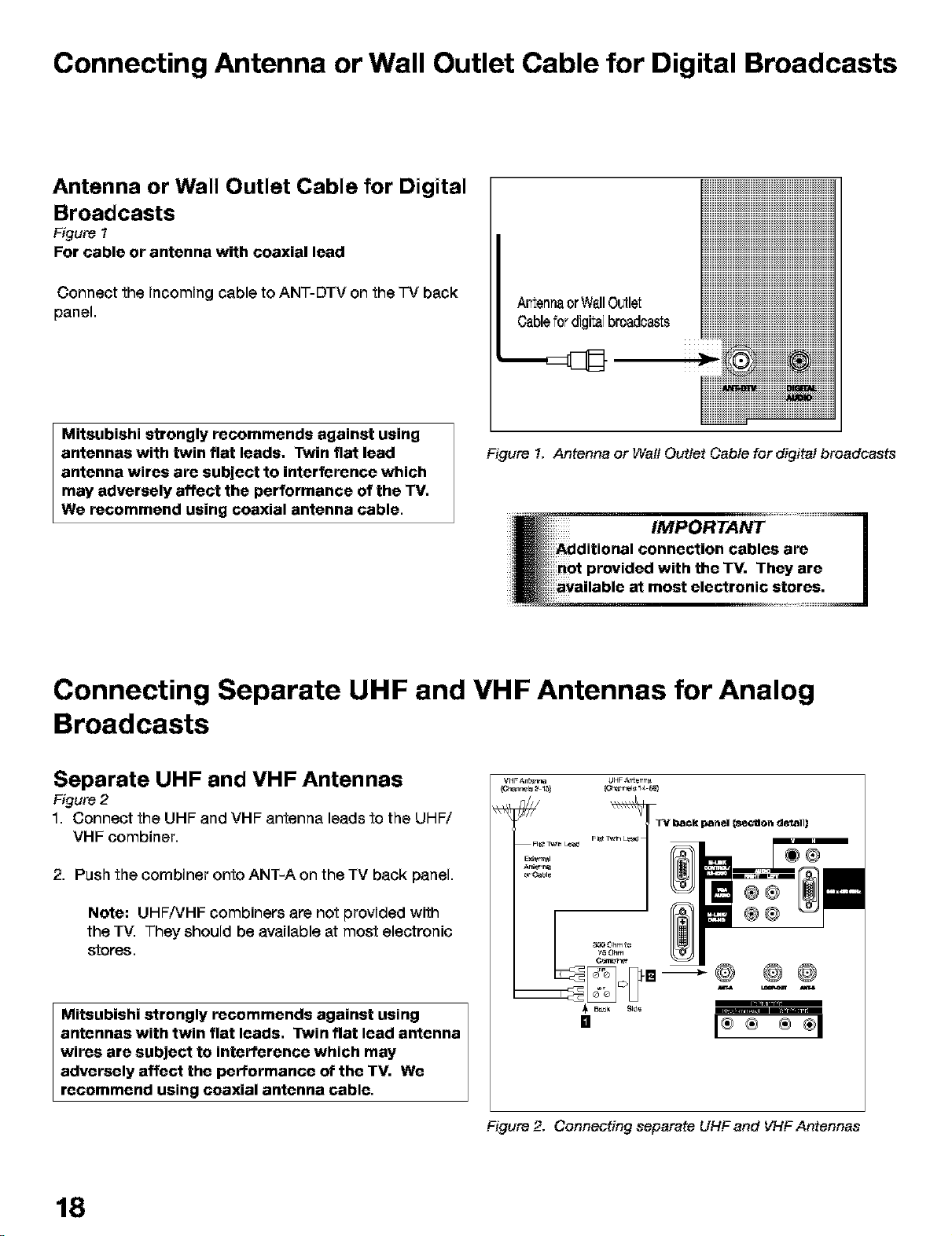
Antenna or Wall Outlet Cable for Digital
Broadcasts
Figure t
For cable or antenna with coaxial lead
Connect the incoming cable to ANT-DTV on the "FVback
panel.
Mitsubishi strongly recommends against using
antennas with twin flat leads, Twin flat lead
antenna wires are subject to interference which
may adversely affect the performance of the TV,
We recommend using coaxial antenna cable.
ArtennaorWallOutlet
Cablefor digitalbroadcasts
Figure 1. Antenna or WattOuttet Cable for digital broadcasts
Connecting Separate UHF and VHF Antennas for Analog
Broadcasts
Separate UHF and VHF Antennas
Figure 2
1. Connect the UHF and VHF antenna leads to the UHF/
VHF combiner.
2. Push the combiner onto ANT-A on the TV back panel.
Note: UHF/VHF combiners are not provided with
the TV. They should be available at most electronic
stores.
Mitsubishi strongly recommends against using
antennas with twin flat leads, Twin flat lead antenna
wires are subject to interference which may
adversely affect the performance of the TV. We
recommend using coaxial antenna cable.
18
_____@
mm
I®÷ ®÷I
ure 2. Connecting separete UHF and VHFAntennas
Page 19
Connecting a Single Analog Antenna, Wall Outlet Cable
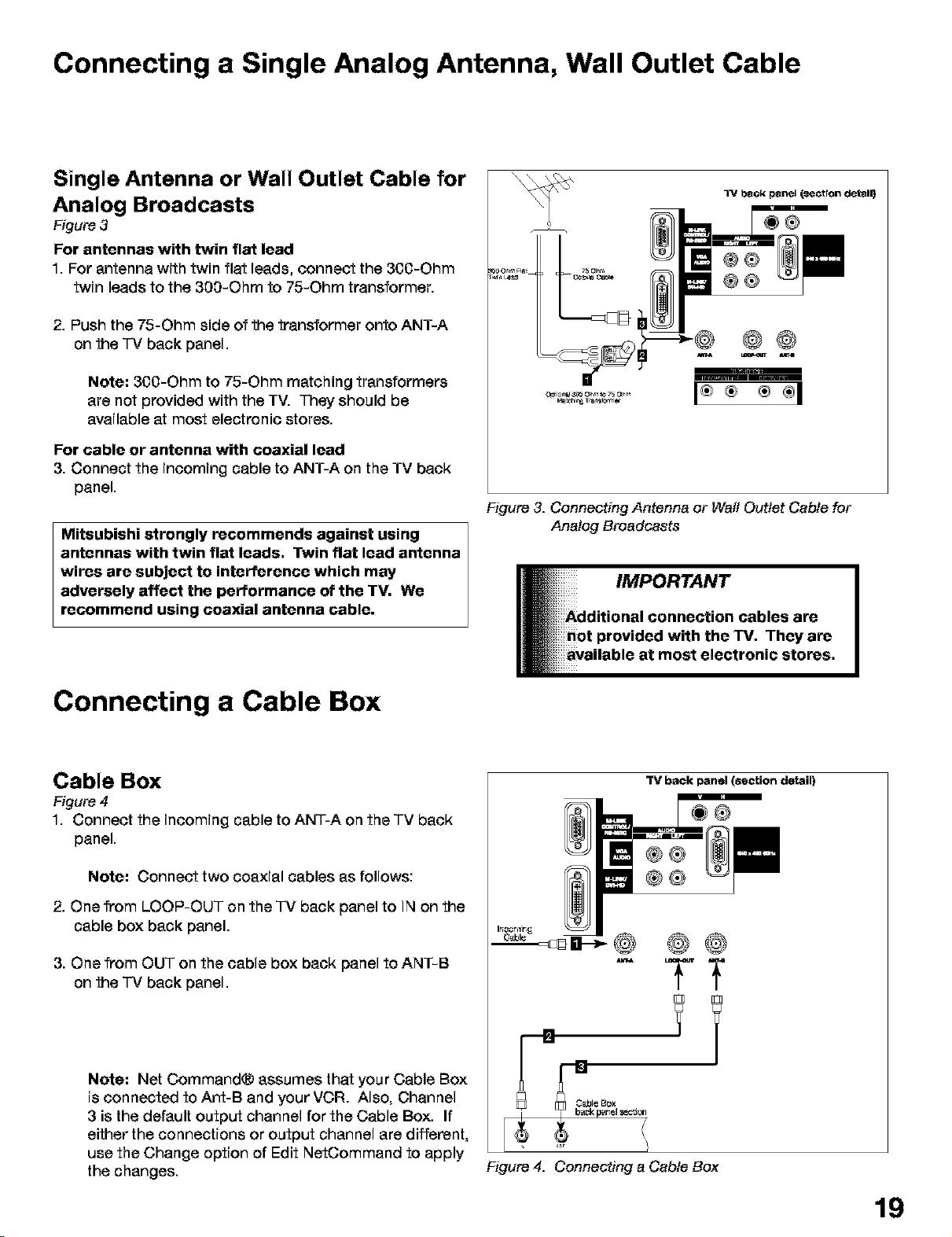
Single Antenna or Wall Outlet Cable for
Analog Broadcasts
Figure 3
For antennas with twin flat lead
1 For antenna with twin flat leads, connect the 300-Ohm
twin leads to the 300-Ohm to 75-Ohm transformer
2. Push the 75-Ohm side of the transformer onto ANT-A
on the -IV back panel.
Note; 300-Ohm to 75-Ohm matching transformers
are not provided with the TV. They should be
available at most electronic stores.
For cable or antenna with coaxial lead
3. Connect the incoming cable to ANT-A on the TV back
panel.
Mitsubishi strongly recommends against using
antennas with twin flat leads. Twin flat lead antenna
wires are subject to interference which may
adversely affect the performance of the TV. We
recommend using coaxial antenna cable.
Figure 3. Connecting Antenna or Wail Outlet Cable for
Analog Broadcasts
®@
®@
@@
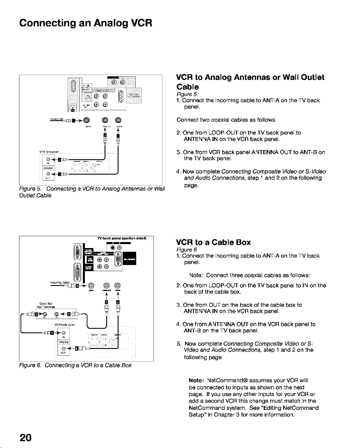
Connecting a Cable Box
Cable Box
Figure 4
1. Connect the incoming cable to ANT-A on the TV back
panel.
Note; Connect two coaxial cables as follows:
2. One from LOOP-OUT on the -IV back panel to IN on the
cable box back panel.
3. One from OUT on the cable box back panel to ANT-B
on the -IV back panel.
Note; Net Command® assumes that your Cable Box
is connected to Ant-B and your VCR. Also, Channel
3 is the default output channel for the Cable Box. If
either the connections or output channel are different,
use the Change option of Edit NetOommand to apply
the changes.
"13/back panel (section detail)
Figure 4. Connecting a Cable Box
19
Page 20
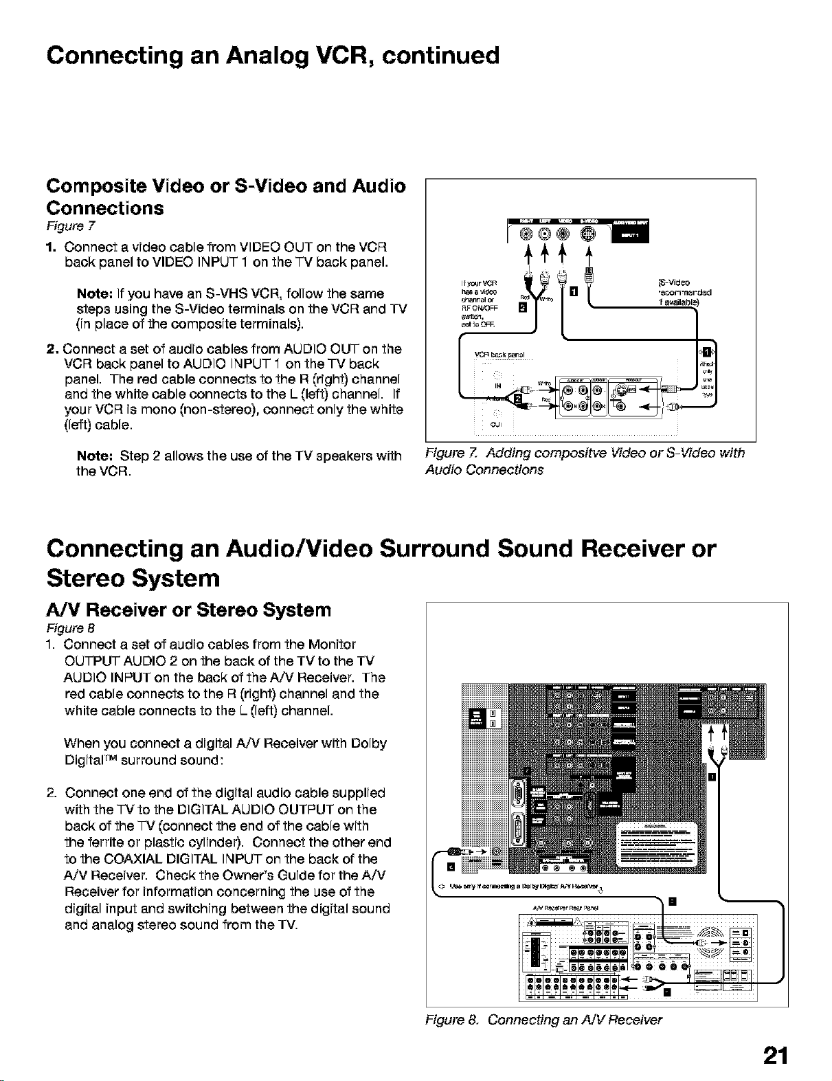
Connecting an Analog VCR
Figure 5. Connecting a VCR to Analog Antennas or Waff
Outlet Cable
VCR to Analog Antennas or Wall Outlet
Cable
Figure 5
1. Connect the incoming cable to ANT-A on the TV back
panel.
Connect two coaxial cables as follows
2. One from LOOP-OUT on the TV back panel to
ANTENNA IN on the VCR back panel.
3. One from VCR back panel ANTENNA OUT to ANT-B on
the TV back panel.
4. Now complete Connecting Composite Video or S-Video
andAudio Connections, step 1 and 2 on the following
page.
Re&r Ten_ik_z_$
Figure 6. Connecting a VCR to a Cable Box
VCR to a Cable Box
Figure 6
1. Connect the incoming cable to ANT-A on the TV back
panel.
Note: Connect three coaxial cables as follows:
2. One from LOOP-OUT on the TV back panel to IN on the
back of the cable box.
3. One from OUT on the back of the cable box to
ANTENNA IN on the VCR back panel.
4. One from ANTENNA OUT on the VCR back panel to
ANT-B on the "]-Vback panel.
5. Now complete Connecting Composite Video orS-
Video andAudio Connections, step 1 and 2 on the
following page.
Note: NetCommand® assumes your VCR will
be connected to inputs as shown on the next
page. If you use any other inputs for your VCR or
add a second VCR this change must match in the
NetCommand system. See "Editing NetOommand
Setup" in Chapter 3 for more information.
20
Page 21
Connecting an Analog VCR, continued
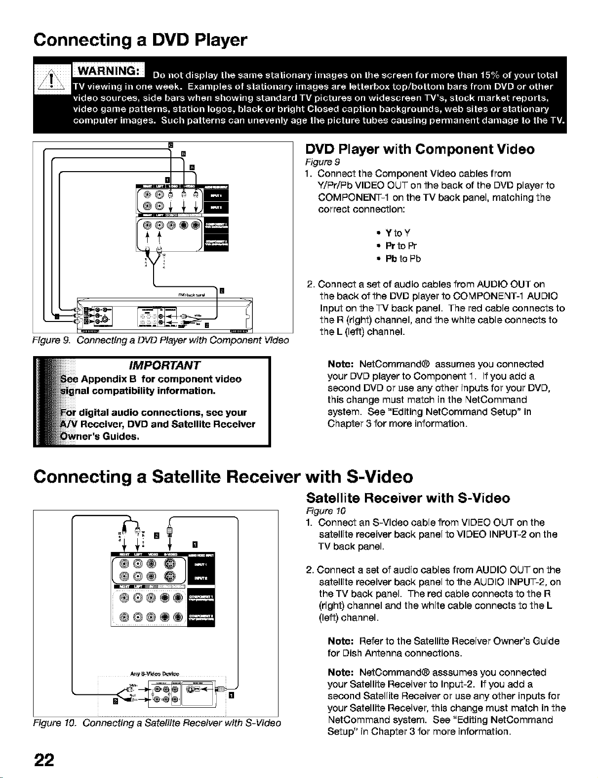
Composite Video or S-Video and Audio
Connections
Figure 7
1. Connect a video cable from VIDEO OUT on the VCR
back panel to VIDEO INPUT 1 on the TV back panel.
Note: If you have an S-VHS VCR, follow the same
steps using the S-Video terminals on the VCR and TV
(in place of the composite terminals).
2. Connect a set of audio cables from AUDIO OUT on the
VCR back panel to AUDIO INPUT 1 on the TV back
panel. The red cable connects to the R (right) channel
and the white cable connects to the L (left) channel. If
your VCR is mono (non-stereo), connect only the white
(left) cable.
Note: Step 2 allows the use of the TV speakers with
the VCR.
Figure Z Adding compoaitve Video or S-Video with
Audio Connections
Connecting an Audio/Video Surround Sound Receiver or
Stereo System
A/V Receiver or Stereo System
Figure 8
1. Connect a set of audio cables from the Monitor
OUTPUT AUDIO 2 on the back of the TV to the TV
AUDIO INPUT on the back of the A/V Receiver. The
red cable connects to the R (right) channel and the
white cable connects to the L (left) channel.
When you connect a digital A/V Receiver with Dolby
DigitaF Msurround sound:
2. Connect one end of the digital audio cable supplied
with the "]-Vto the DIGITAL AUDIO OUTPUT on the
back of the "IV (connect the end of the cable with
the ferrite or plastic cylinder). Connect the other end
to the COAXIAL DIGITAL INPUT on the back of the
A/V Receiver. Check the Owner's Guide for the A/V
Receiver for information concerning the use of the
digital input and switching between the digital sound
and analog stereo sound from the TV.
Figure& Connecting an A/V Receiver
21
Page 22
Connecting a DVD Player
[]
[]
[]
[]
Figure 9. Connecting a DVD Player with Component Video
DVD Player with Component Video
Figure 9
1. Connect the Component Video cables from
Y/PriPb VIDEO OUT on the back of the DVD player to
COMPONENT-1 on the TV back panel, matching the
correct connection:
• YtoY
• Pr to Pr
• Pb to Pb
2. Connect a set of audio cables from AUDIO OUT on
the back of the DVD player to COMPONENT-1 AUDIO
Input on the "]-Vback panel. The red cable connects to
the R (right) channel, and the white cable connects to
the L (left) channel.
Note: NetCommand® assumes you connected
your DVD player to Component 1. If you add a
second DVD or use any other inputs for your DVD,
this change must match in the NetCommand
system. See "Editing NetCommand Setup" in
Chapter 3 for more information.
Connecting a Satellite Receiver with S-Video
Satellite Receiver with S-Video
Figure t0
=¢ 1. Connect an S-Video cable from VIDEO OUT on the
[] _ satellite receiver back panel to VIDEO INPUT-2 on the
"4 _,i _' [] TV back panel.
2. Connect a set of audio cables from AUDIO OUT on the
satellite receiver back panel to the AUDIO INPUT-2, on
the TV back panel. The red cable connects to the R
(right) channel and the white cable connects to the L
(left) channel.
Note: Refer to the Satellite Receiver Owner's Guide
for Dish Antenna connections.
At!y It_V'vJ¢o _!_
Figure 10. Connecting a Satellite Receiver with S-Video
Note: NetOommand® asssumes you connected
your Satellite Receiver to Input-2. If you add a
second Satellite Receiver or use any other inputs for
your Satellite Receiver, this change must match in the
NetCommand system. See "Editing NetCommand
Setup" in Chapter 3 for more information.
22
Page 23
Connecting an External Digital TV (DTV or HDTV) Receiver
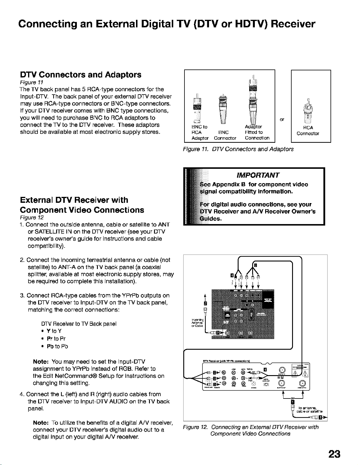
DTV Connectors and Adaptors
Figure tl
The TV back panel has 5 RCA-type connectors for the
Input-DTV. The back panel of your external D-IV receiver
may use RCA-type connectors or BNC-type connectors.
If your DTV receiver comes with BNC type connections,
you will need to purchase BNC to RCA adaptors to
connect the -IV to the D-IV receiver. These adaptors
should be available at most electronic supply stores.
BNC to
RCA BNC
Adaptor Connector
Figure 11. DTV Connectors and Adaptors
:or
Fittedto
Connection
or
RCA
Conne_or
External DTV Receiver with
Component Video Connections
Figure t2
1. Connect the outside antenna, cable or satellite to ANT
or SATELLITE IN on the DTV receiver (see your DTV
receiver's owner's guide for instructions and cable
compatibility).
2. Connect the incoming terrestrial antenna or cable (not
satellite) to ANT-A on the TV back panel (a coaxial
splitter, available at most electronic supply stores, may
be required to complete this installation).
3. Connect ROA-type cables from the YPrPb outputs on
the DTV receiver to Input-DTV on the "TVback panel,
matching the correct connections:
DTV Receiver to TV Back panel
• YtoY
• Pr to Pr
• Pbto Pb
Note: You may need to set the Input-DTV
assignment to YPrPb instead of RGB. Refer to
the Edit NetOommand® Setup for instructions on
changing this setting.
4. Connect the L (left) and R (right) audio cables from
the DTV receiver to Input-DTV AUDIO on the TV back
panel.
Note: To utilize the benefits of a digital A/V receiver,
connect your DTV receiver's digital audio out to a
digital input on your digital A/V receiver.
t_o t
[]
to ar _r_tlna,
Figure 12. Connecting an Extema/ DW Receiver with
Component Video Connections
23
Page 24
Connecting an Extemal Digital TV (DTV or HDTV) Receiver with
RGB, HV Video Connections
It may be necessary to obtain a VGA to RGB
audio adaptor cable. These are available at most
computer stores and many electronic stores. Some
of the adaptor cables have RCA type connector
ends, others have BNC type ends and will require
adaptors as shown on page 21.
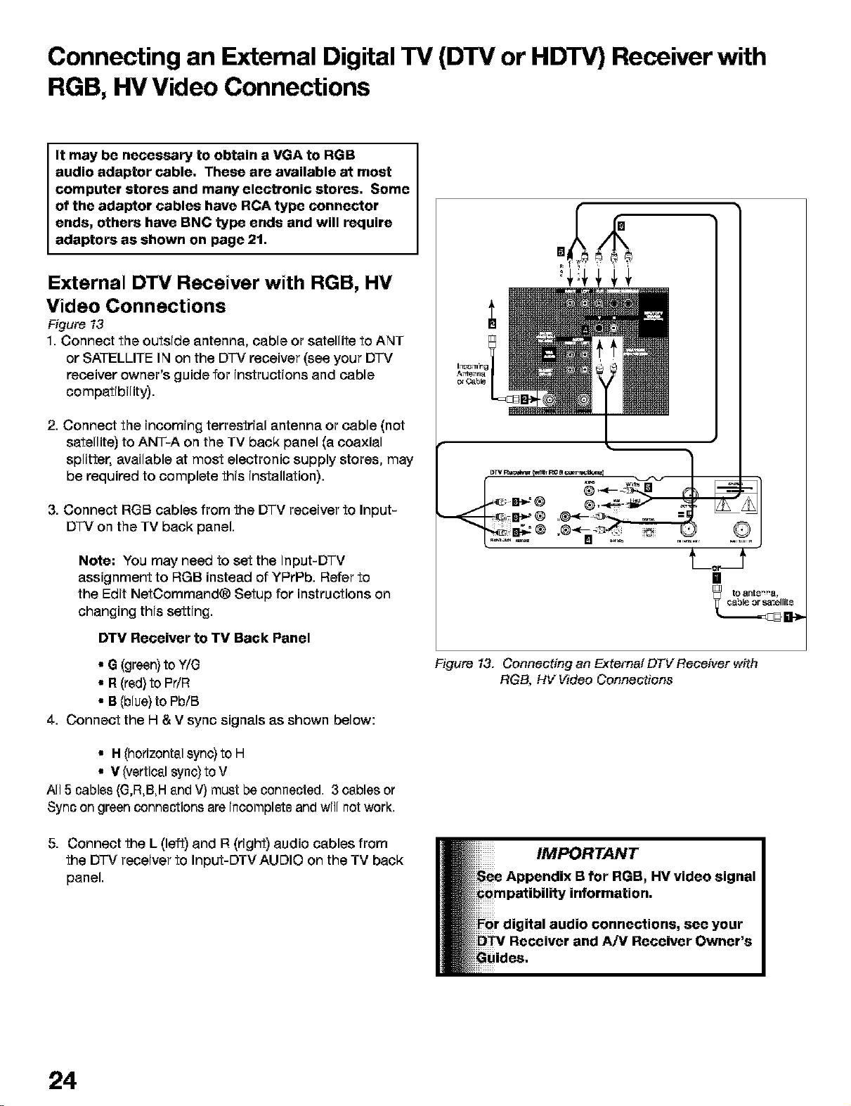
External DTV Receiver with RGB, HV
Video Connections
Figure t3
1. Connect the outside antenna, cable or satellite to ANT
or SATELLITE IN on the D']-V receiver (see your DTV
receiver owner's guide for instructions and cable
compatibility).
2. Connect the incoming terrestrial antenna or cable (not
satellite) to ANT-A on the TV back panel (a coaxial
splitter, available at most electronic supply stores, may
be required to complete this installation).
3. Connect RGB cables from the DTV receiver to Input-
D-IV on the TV back panel.
Note: You may need to set the Input-DTV
assignment to RGB instead of YPrPb. Refer to
the Edit NetOommand® Setup for instructions on
changing this setting.
DTV Receiver to TV Back Panel
• G (green)to Y/G
• R(red) to PdR
• B (blue) to Pb/B
4. Connect the H & V sync signals as shown below:
• H (horizontsl sync) to H
• V (verticsl sync) to V
All 5 cables (G,R,B,H snd V) must be connected. 3 csbles or
Sync on green connections are incomplete and will not work.
5. Connect the L (left) and R (right) audio cables from
the D']-V receiver to Input-DTV AUDIO on the TV back
panel.
[]
tO 8NtS'n8,
Figure 13. Connecting an Extemal DTV Receiver with
RGB, HV Video Connections
24
Page 25
Connecting MonitorLink TM with MonitorLink Control or DVI
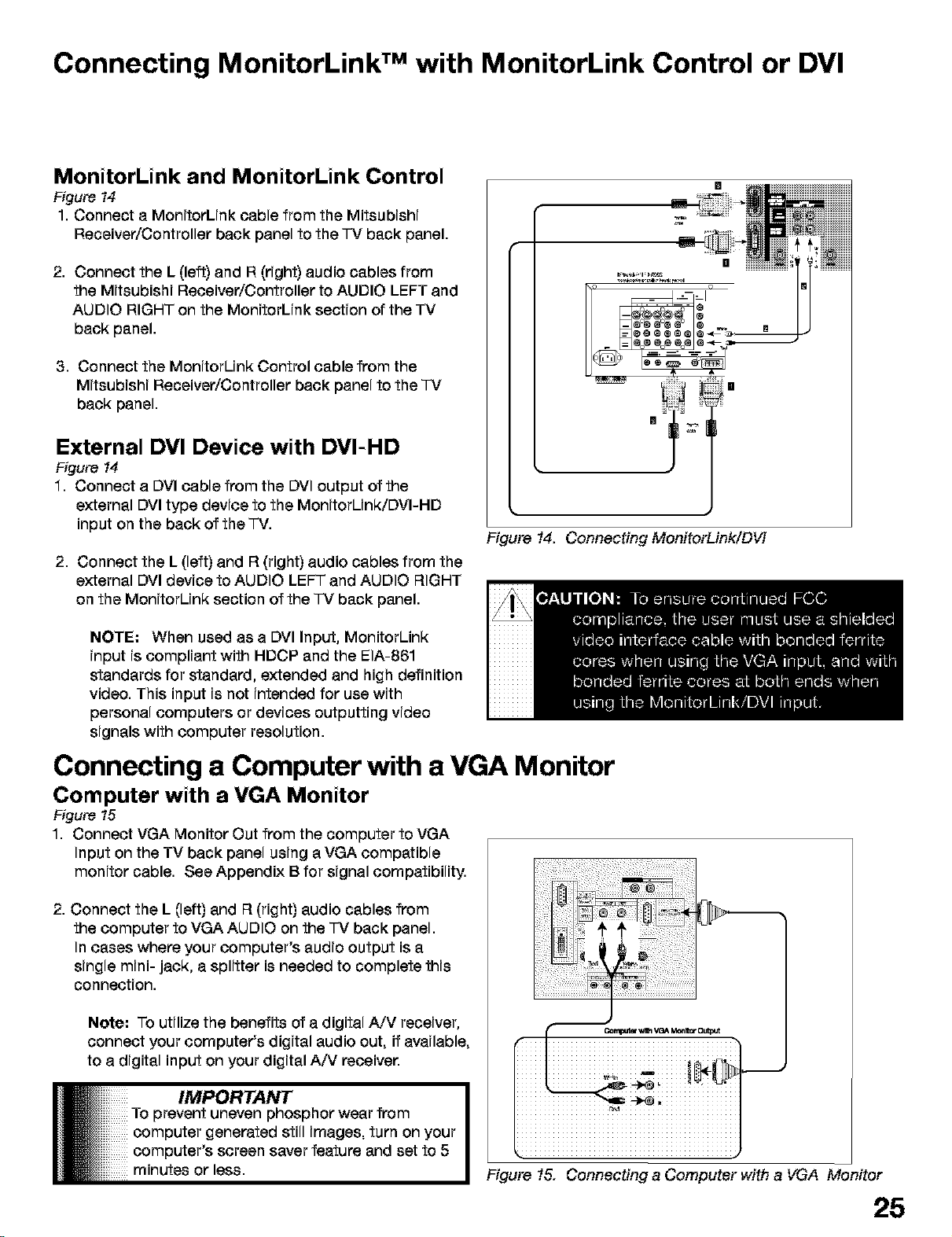
MonitorLink and MonitorLink Control
Figure t4
1. Connect a MonitorLink cable from the Mitsubishi
Receiver/Controller back panel to the TV back panel.
2. Connect the L (left) and R (right) audio cables from
the Mitsubishi Receiver/Controller to AUDIO LEFT and
AUDIO RIGHT on the MonitorLink section of the TV
back panel.
3. Connect the MonitorUnk Control cable from the
Mitsubishi Receiver/Controller back panel to the TV
back panel.
External DVI Device with DVI-HD
Figure 14
1. Connect a DVI cable from the DVI output of the
external DVI type device to the MonitorUnk/DVI-HD
input on the back of the TV.
2. Connect the L (left) and R (right) audio cables from the
external DVI device to AUDIO LEFT and AUDIO RIGHT
on the MonitorUnk section of the TV back panel.
[]
[]
Figure 14. Connecting MonitorLink/DVl
NOTE: When used as a DVI Input, MonitorLink
input is compliant with HDCP and the EIA-861
standards for standard, extended and high definition
video. This input is not intended for use with
personal computers or devices outputting video
signals with computer resolution.
Connecting a Computer with a VGA Monitor
Computer with a VGA Monitor
Figure t5
1. Connect VGA Monitor Out from the computer to VGA
Input on the TV back panel using a VGA compatible
monitor cable. See Appendix B for signal compatibility.
2. Connect the L (left) and R (right) audio cables from
the computer to VGA AUDIO on the TV back panel.
In cases where your computer's audio output is a
single mini- jack, a splitter is needed to complete this
connection.
Note: To utilize the benefits of a digital A/V receiver,
connect your computer's digital audio out, if available,
to a digital input on your digital A/V receiver.
To prevent uneven phosphor wear from
computer generated still images, turn on your
Ii IMPORTANT
computer's screen saver feature and set to 5
minutes or less.
iiiiiii__.iiiiiiiiiiiiiiiii
Figure 15. Connecting a Computer with a VGA Monitor
25
Page 26
Connecting the IR Emitter NetCommand ® or IR Repeater
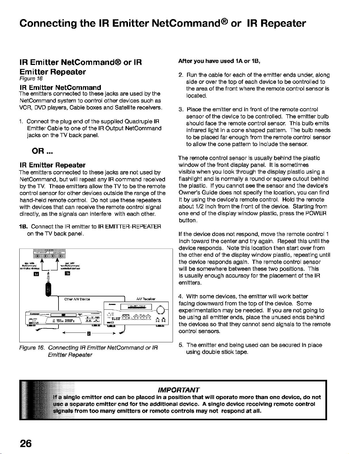
IR Emitter NetCommand® or IR
Emitter Repeater
Figure t6
IR Emitter NetCommand
The emitters connected to these jacks are used by the
NetCommand system to control other devices such as
VCR, DVD players, Cable boxes and Satellite receivers.
1. Connect the plug end of the supplied Quadruple IF!
Emitter Cable to one of the IR Output NetCommand
jacks on the -IV back panel.
OR ===
IR Emitter Repeater
The emitters connected to these jacks are not used by
NetCommand, but will repeat any IF!command received
by the "FV.These emitters allow the TV to be the remote
control sensor for other devices outside the range of the
hand-held remote control. Do not use these repeaters
with devices that can receive the remote control signal
directly, as the signals can interfere with each other.
lB. Connect the IF{emitter to IF!EMITTER-REPEATER
on the -IV back panel.
!
After you have used 1A or 1B,
2,
Run the cable for each of the emitter ends under, along
side or over the top of each device to be controlled to
the area of the front where the remote control sensor is
located.
, Place the emitter end in front of the remote control
sensor of the device to be controlled. The emitter bulb
should face the remote control sensor. This bulb emits
infrared light in a cone shaped pattern. The bulb needs
to be placed far enough from the remote control sensor
to allow the cone pattern to include the sensor.
The remote control sensor is usually behind the plastic
window of the front display panel. It is sometimes
visible when you look through the display plastic using a
flashlight and is normally a round or square cutout behind
the plastic. If you cannot see the sensor and the device's
Owner's Guide does not specify the location, you can find
it by using the device's remote control. Hold the remote
about 1/2 inch from the front of the device. Starting from
one end of the display window plastic, press the POWER
button.
If the device does not respond, move the remote control 1
inch toward the center and try again. Repeat this until the
device responds. Note this location then start over from
the other end of the display window plastic, repeating until
the device responds again. The remote control sensor
will be somewhere between these two positions. This
is usually enough accuracy for the placement of the IR
emitters.
4. With some devices, the emitter will work better
facing downward from the top of the device. Some
experimentation may be needed. If you are not going to
be using all emitter ends, place the unused ends behind
the devices so that they cannot send signals to the remote
control sensors.
Figure 16. Connecting fR Emitter NetCommand or fR
Emitter Repeater
26
5. The emitter end being used can be secured in place
using double stick tape.
Page 27
Page 28
Remote Control Functions: Overview
Overview
Figure t, fo//owing page
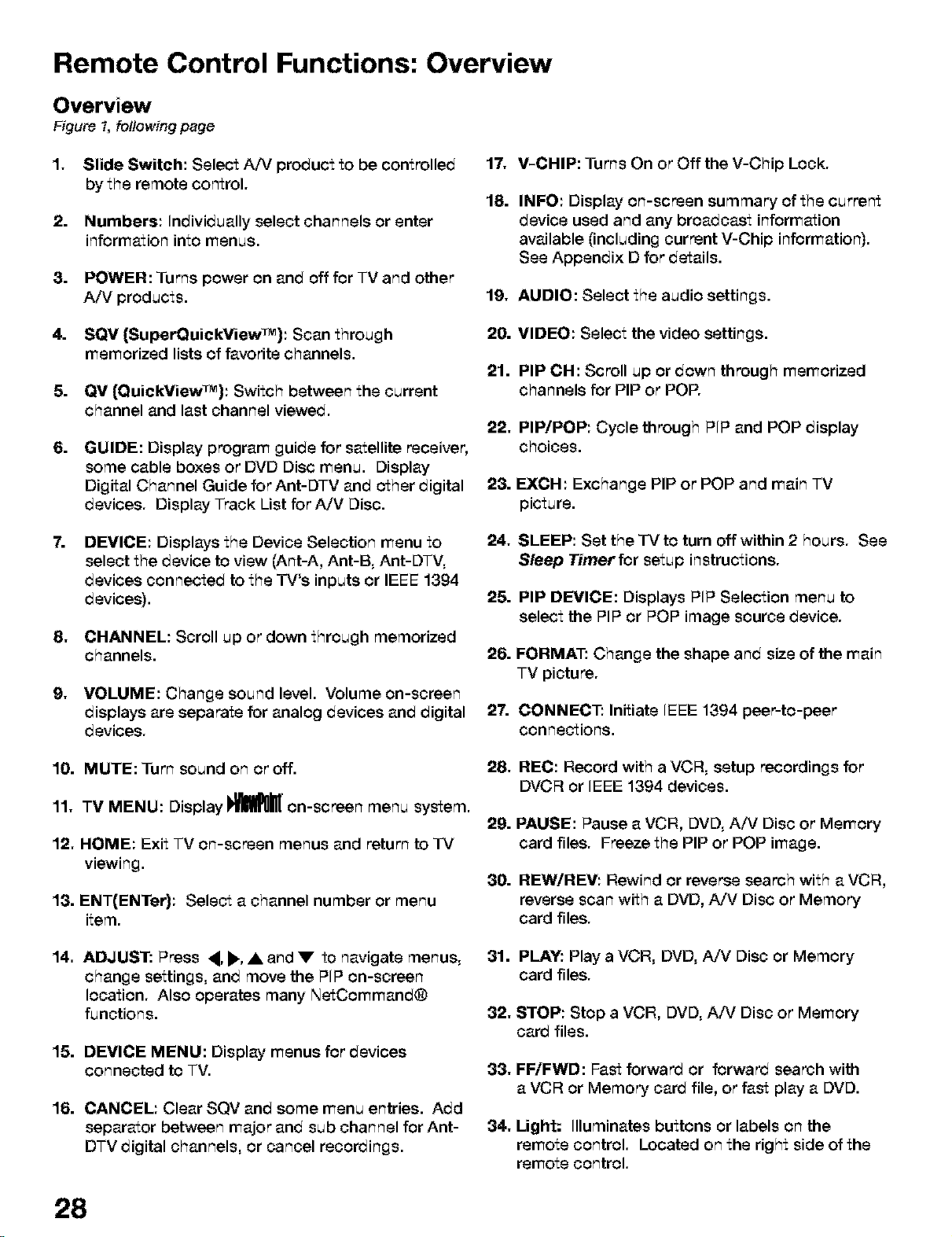
,
Slide Switch: Select A/V product to be controlled 17.
by the remote control.
2.
Numbers: Individually select channels or enter
information into menus.
3.
POWER: Turns power on and off for TV and other
A/V products.
=
SQV {SuperQuickView_M): Scan through
memorized lists of favorite channels.
5.
QV (OuickView_): Switch between the current
channel and last channel viewed.
6.
GUIDE: Display program guide for satellite receiver,
some cable boxes or DVD Disc menu. Display
Digital Channel Guide for Ant-DTV and other digital
devices. Display Track List for A!V Disc.
7.
DEVICE: Displays the Device Selection menu to
select the device to view (Ant-A, Ant-B, Ant-DTV,
devices connected to the TV's inputs or IEEE 1394
devices).
,
CHANNEL: Scroll up or down through memorized
channels.
9,
VOLUME: Change sound level. Volume on-screen
displays are separate for analog devices and digital 2"/'.
devices.
V-CHIP: Turns On or Off the V-Chip Lock.
18.
INFO: Display on-screen summary of the current
device used and any broadcast information
available (including current V-Chip information).
See Appendix D for details.
19, AUDIO: Select the audio settings.
20. VIDEO: Select the video settings.
21. PIP CH: Scroll up or down through memorized
channels for PIP or POP.
22, PIP/POP: Cycle through PIP and POP display
choices.
23. EXCH: Exchange PIP or POP and main TV
picture.
24, SLEEP: Set the IV to turn off within 2 hours. See
Sleep Timer for setup instructions.
25. PIP DEVICE: Displays PIP Selection menu to
select the PIP or POP image source device.
26. FORMAT: Change the shape and size of the main
TV picture.
CONNECT: Initiate IEEE 1394 peer-to-peer
connections.
10. MUTE: Turn sound on or off.
11, TV MENU: Display _' on-screen menu system.
12, HOME: Exit TV on-screen menus and return to IV
viewing.
13. ENT(ENTer): Select a channel number or menu
item.
14, ADJUST: Press ,, _., • and • to navigate menus,
change settings, and move the PIP on-screen
location. Also operates many NetCommand®
functions.
15. DEVICE MENU: Display menus for devices
connected to TV.
16. CANCEL: Clear SQV and some menu entries. Add
separator between major and sub channel for Ant-
DTV digital channels, or cancel recorctings.
28
28. HEC: Record with a VCR, setup recordings for
DVCR or IEEE 1394 devices.
29. PAUSE: Pause a VCR, DVD, A/V Disc or Memory
card files. Freeze the PIP or POP image.
30. HEWiHEV: Rewind or reverse search with a VCR,
reverse scan with a DVD, A/V Disc or Memory
card files.
31. PLAY: Play a VCR, DVD, AiV Disc or Memory
card files.
32, STOP: Stop a VCR, DVD, A/V Disc or Memory
card files.
33, FFiFWD: Fast forward or forward search with
a VCR or Memory card file, or fast play a DVD.
34, Light: Illuminates buttons or labels on the
remote control. Located on the right side of the
remote control.
Page 29
Remote Control Functions:Operation and Care
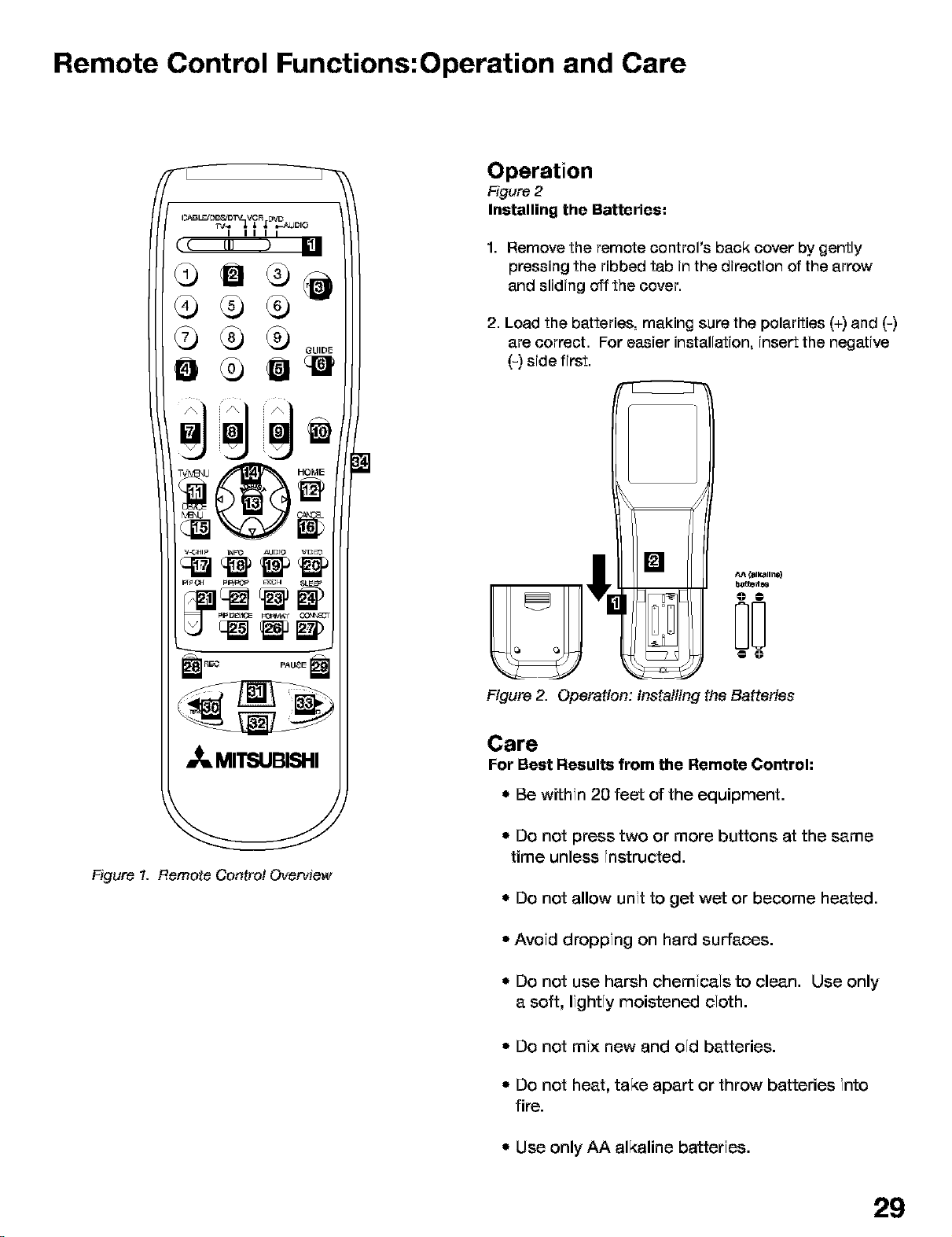
Operation
Figure 2
Installing the Batteries:
1. Remove the remote control's back cover by gently
pressing the ribbed tab in the direction of the arrow
and sliding off the cover.
2. Load the batteries, making sure the polarities (+) and (-)
are correct. For easier installation, insert the negative
(-) side first.
•_, MITSUBISHI
Figure t. Remote Control Overview
o
Figure 2. Operation: installing the Batteries
Care
For Best Results from the Remote Control:
• Be within 20 feet of the equipment.
* Do not press two or more buttons at the same
time unless instructed.
* Do not allow unit to get wet or become heated.
* Avoid dropping on hard surfaces.
* Do not use harsh chemicals to clean. Use only
a soft, lightly moistened cloth.
* Do not mix new and old batteries.
. Do not heat, take apart or throw batteries into
fire.
• Use only AA alkaline batteries.
29
Page 30
Programming the Remote Control to Control NetCommand
A/V Products
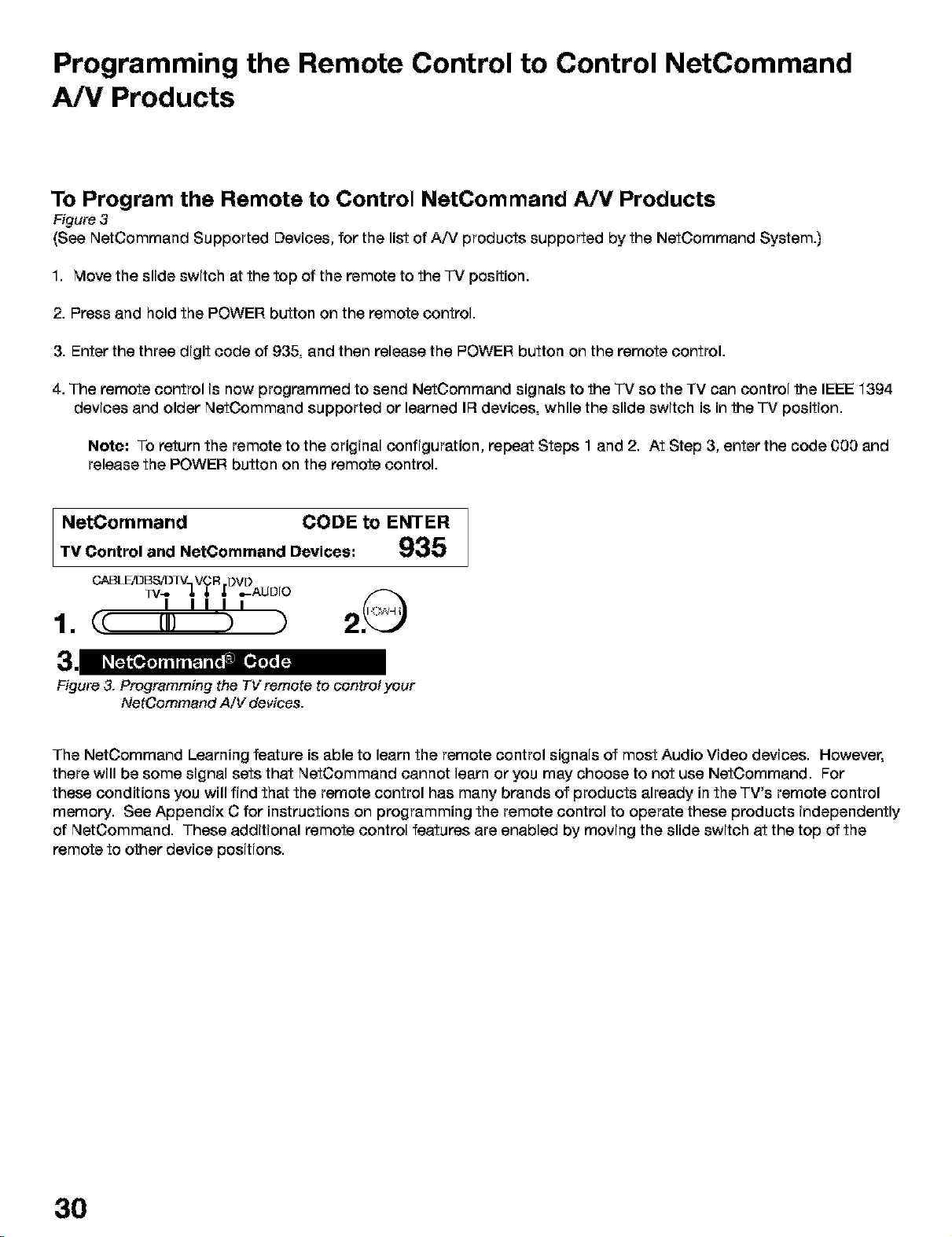
To Program the Remote to Control NetCommand A/V Products
Figure 3
(See NetCommand Supported Devices, for the list of A/V products supported by the NetCommand System.)
1. Move the slide switch at the top of the remote to the "IV position.
2. Press and hold the POWER button on the remote control.
3. Enter the three digit code of 935, and then release the POWER button on the remote control.
4. The remote control is now programmed to send NetCommand signals to the -IV so the TV can control the IEEE 1394
devices and older NetCommand supported or learned IF{devices, while the slide switch is in the -IV position.
Note: To return the remote to the original configuration, repeat Steps 1 and 2. At Step 3, enter the code 000 and
release the POWER button on the remote control.
NetComrnand CODE to ENTER
TV Control and NotCommand Devices," 935
CABLEiDBSJDIV_ VCR DVD
33/-- J, _, ,_ =.-AUDIO
I IIII
1. (c [,} ) ) 2
Figure 3. Programming the TVremote to control your
The NetOommand Learning feature is able to learn the remote control signals of most Audio Video devices. However,
there will be some signal sets that NetCommand cannot learn or you may choose to not use NetOommand. For
these conditions you will find that the remote control has many brands of products already in the TV's remote control
memory. See Appendix C for instructions on programming the remote control to operate these products independently
of NetCommand. These additional remote control features are enabled by moving the slide switch at the top of the
remote to other device positions.
NetCommand A/V devices.
30
Page 31

3D Graphical RiewPoiltMenu System
Your "TVhas a special control system called NetCommand ® that will control IEEE 1394 devices and selected older
devices. For instructions on operating these control features, see the next page.
Your TV also has Mitsubishi's exclusive 3D Graphical
!_r_n[ on-screen operating system, which provides
on-screen information for menu choices and changes,
using the "FV's remote control.
Main Menu: This screen will always be the first screen that
appears when you press the remote's 7-VMENU button
The following buttons on your remote control help you
navigate within the i_m_lllm • system :
DEVICOE
navigation buttons
_ A picture (icon) will be highlighted when
_'_ selected with the ADJUST arrows. When
_,_ selected, the appropriate menu appears.
You may then make changes within the
_:;;_'_ menu or access sub-menus, if available.
You can also access sub-menus from a
button. Sometimes, when you select a
button an automatic function begins.
The _l_0_m" system includes the following special
features:
• The currently selected icon or button is
highlighted with a yellow outline; the text color is
yellow.
* On-screen instructions, shown in the message
line at the bottom of the menu, provide feature
selection and adjustment information.
• Some on-screen menu options must be set before
other options are available.
1. ADJUST _ or • to select the menu item you want to
change.
2. ADJUST • or • to change the settings.
3. ENT(er) to enter into a menu, start an automatic
function or select a checkbox.
4. CANCEL to clear a setting or stop an automatic
function.
5. MENU to display the main menu or move back one
menu screen at a time.
6. HOME to exit all menus and return to TV viewing.
You can change text boxes by pressing ADJUST • or
• . Some text boxes have preset labels. "Other" boxes
allow you to select letters, numbers or characters to
customize names.
When customizing names, pressADJUSTAor• to
select letters, numbers or characters. Press ENT(er) to
move to the next character position. Use CANCEL to
erase letters, numbers or characters or move one space
backward.
31
Page 32

Using the Remote Control with NetCommand® Setup
In order to use the TV's NetOommand feature, you need
to provide some detailed information during the setup of
your Mitsubishi TV. You must define the Manufacturer
of the devices that are connected to the television, or
learn the IR code remote control signals for the device
connected. For each device, the input to the "l-Vand
A/_ receiver, and the names for the device are pre-set
during Initial NetOommand setup. You may change
those inputs or names using the Edit NetCommand or
Learn screens.
Radio Buttons
The setting changes when a radio button is selected
On your remote control, the ADJUST _ and • buttons
allow you to navigate left and right to different selections
on the screen. The ADJUST • and • buttons allow you
to:
* Change the selected radio button
* Change selection in text boxes
* Navigate up and down on the screen
The ENT(er) button allows you to:
* Confirm the selected character when naming a
device
° Add or delete check marks in check boxes
* Select on-screen buttons to change screens
Textbox
Press ADJUST • or • to make a selection.
Control Buttons
Much like the software on your computer, you will use
graphic buttons to navigate through the NetCommand
Setup screen. Highlight the button and press ENT(er) to
select the function.
<Back Button
Use the <Back button to navigate back to the previous
screen.
Next> Button
Use the Next> button to navigate forward to the next
screen,
Checkbox
Checkmarks indicate the item or input is added or
turned On. Press ENT{er) when the Checkbox is
highlighted to add or delete a checkmark. When viewing
the Review screen, a Checkbox reflects which devices
are turned On or Off, or connected to the TV.
32
Cancel Button
The Cancel button will cancel out any changes you
are currently making without saving them into memory.
When you select the Cancel key, NetOommand will
prompt you to confirm that you want to cancel the
changes you are currently making. If you select Cancel
during Initial Setup, You can setup NetOommand later
by selecting the Initial option at the Setup menu.
Page 33

NetCommand® Initial Setup Guide
The easiest way to setup NetCommand is to follow the on-screen directions. For reference, below is a list o_1
the screens that you will use. You will find detailed information regarding each screen in the pages following I
this Guide.
Initial
Initial NetCommand Setup:
When you first turn on your TV.
You may Cancel at any screen.
l
Language Screen
Page 35 Figure 1
/
l
Information Screen
Page 35 Figure 2
l
Device Setup Screen (used
when manufacturer is known).
If the manufacturer is unknown,
see Edit NetOommand for the
device.
Page 35 Figure 3
l
Review Screen
Page 36 Figure 4
Finish Screen
Page 36 Figure 5
33
Page 34

NetCommand ® Editing Guide
The easiest way to setup NetCommand is to follow the on-screen directions. For reference, below is a list of1
the screens that you will use. You will find detailed information regarding each screen in the pages following I
this Guide.
Cable Box elec_erJ
/
÷
i
34
Page 35

NetCommand e Initial Setup
When you first power On your new Mitsubishi TV, the initial setup screens appear. In order to use NetCommand,
select these screens after you have connected the compatible equipment to the TV. Most IR remote control signal
formats can be learned by NetOommand.
Language Screen
Figure t
When you first turn on your q-V,the Welcome screen
displays and asks you to select either English or Spanish
as the language for the on-screen menus. The default
language is English. To change Language later, use
Setup in the Main Menu. Selecting Cancel at this screen
will cause the default language (English) to appear.
Figure t. Language screen
NetCommand (Information) Screen
Figure 2
The NetCommand (Information) Screen describes how
to start or delay the initial NetOommand Setup. This
screen displays automatically the first time you power
On your new TV, after the Welcome screen.
Device Setup Screen
Figure 3
If the devices connected to the TV are already in
NetCommand memory, you can quickly select them at
this screen. Press ADJUST • or, to move to each device
type. Press ADJUST A, or V to select the manufacturer
of each device type. Select "Other" if the manufacturer
is not listed. Later, you can use the Change setting in the
Edit NetCommand option of the Setup menu to learn the
remote control signals for this device. Select "None" for
device types that are not connected.
If the manufacturer for your A/V Receiver is not listed, you
cannot select "Other". Instead, select "None". Later, you
can use the "Add" feature in the Edit NetCommand option
of the Setup menu to learn the remote control signals for
this device.
If you have a camcorder connected, check the Camcorder
box. NetCommand will not be able to control the
camcorder, but will reserve the front input to use with the
camcorder. When you are finished, select Next:, and
press ENT(er).
Note: If you selected "Other" for any of the device
names, the TV can "Learn" the connected device
(see page 37).
Figure 2. fnformatien screen
If the NetOommand Setup is cancelled before it's
completed, you can restart the NetCommand setup by:
"1. A press of TV MENU on the remote control to display
the TV Main menu.
2. Select Setup. The available options for NetCommand
are: Add, Review or Initial. Change and Delete will be
grayed out.
3. Press ADJLIST A, V, • or,to select Initial.
4. Press ENT(er). The Device Setup screen displays.
Figure 3. Device Setup screen
IMPORTANT
ig
| NetCommand. You may also set up
a later time by choosing
from the Main menu, then selecting
Edit NetCommand menu.
35
Page 36

NetCommand® Initial Setup, continued
Review Screen
Figure 4
Afer you have made your device choices the Review
Screen will display. It is important to review the settings
to ensure that they are correct. If necessary, you can
use <Back to return to the Device Setup screen to make
changes.
Note: The Review screen lists the -IV input and A/V
Receiver input used with each device. You must
correctly identify the inputs you used when you
connected the devices. If you have not connected
your devices, write down these inputs as a guide. If
you cannot use these inputs, or if you would like to
change the name of a device, use the instructions in
Edit NetCommand to make necessary changes.
Note: Ifyou select Next> on the Review screen, all
selections made are finalized.
On the Review Screen, adding or deleting check marks
will turn the adjacent devices, memory cards or inputs On
or Off. If 1394 devices are not connected to the TV, the
1394 Name list will not appear on the Review screen.
Finish Screen
Figure -5
To finalize your selectioms amd complete the
NetCommamd setup, select Finish from the Finish
screen.
Note: If you wish to chamge amyof the pre-
configured imputs or names for the devices, or add
devices not in the pre-comfigured setup, select
Edit to display Edit NetOommand memu.
If your A/V Receiver was mot listed, select Edit to assign
all devices to new AVR inputs.
Figure 4. Review screen
Figure 5. Finish screen
It is still necessary to memorize the available chammels
for AmtemmaA, Amtenma Bamd Antemma DTV. You may
do that by going to the TV Maim menu and selecting
Amtenna. Imstructioms to memorize chammels are found
imthe Amtenna memu section.
36
Page 37

Edit NetCommand®, Adding an A/V Receiver
A/V Receiver Screen
Figure 6
If you selected "None" as the manufacturer of the
A/V Receiver connected to the -IV during the initial
NetCommand Setup, you may Add the A/V Receiver
and have NetOommand learn it. The same screens are
displayed if using Edit NetCommand.
Figure 6. A/V Receiver screen
Choose ONE of these options:
3. Select "Other", skip Learn and select Next>. This will
allow the device to appear and will allow NetCommand
to switch inputs to use this device. However,
NetCommand will not be able to control this device.
Later you may use the "Change" option in the Setup
menu to learn the remote control signals.
After selecting Next>, the screens that follow are: the
AV Receiver Input screen (Figure 7), Name screen
(Figure 10), Monitor Out screen (Figure 11), ending with
the Finish screen (Figure 12).
A/V Receiver Inputs
Figure 7
Only if "Other" is selected as the manufacturer, after
selecting "Learn" and pressing ENT(er), you will see the
A/V Receiver Input screen. After selecting the number of
inputs, this screen will not appear again.
1. Select a recognized manufacturer. The model number
optimized for NetCommand will display at the bottom
of the screen. If a number follows the manufacturer's
name, (example: Mitsubishi 1), this indicates additional
models are optimized for that manufacturer. For many
device types, non-listed models will operate in the
same way as the listed models and you can still use
the pre-loaded setting.
After selecting Next>, the screens that follow are: the
Name Screen (Figure 10), Monitor Out screen (Figure
11), ending with the Finish screen (Figure 12).
2. Select "Other", then highlight "Learn" and press
ENT(er). This will allow you to have NetCommand learn
the remote control signals of this new device.
After selecting "Learn" and pressing ENT(e0, the
screens that fellow are: the A,_ Receiver Inputs screen
(Figure 7), A/V Receiver Input Learn screen (Figure 8),
A/V Receiver Learn screen (Figure 9), Name screen
(Figure 10), Monitor Out screen (Figure 11), ending with
the Finish screen (Figure 12).
Depending on your A/V Receiver's capability, you may
have devices connected to seven (7) A/V inputs. Press
ADJUST • or • to select the number of inputs on your
A/V receiver that have connected devices.
If the number of connected inputs changes, you will need
to delete the A/V Receiver and add it again, as described
above.
Figure Z A/V Receiver Input screen
37
Page 38

Edit NetCommand e, Adding an A/V Receiver, continued
A/V Receiver Input Learn Screen
Figure 8
NetOommand can now learn the remote control signals
used to select each input on the A/VReceiver.
1. Press ADJUST • or • on the TV remote to select the
check box for each function to be learned.
2. Press ENT(er) and the function name will begin to flash
to confirm the ready-to-learn status.
3. Press the button on the A/V Receiver's remote control
that corresponds to the select function. A check mark
will appear and the function name will stop flashing.
This confirms the signal learned status.
4. To test the learned command, press ENT(e0 on the TV
remote. The _V Receiver will perform the selected
function. The A/V Receiver needs to be turned on
and the IR emitters properly placed for the test to be
successful (see page 26 for IR emitter placement).
5. To customize the input names, press ADJUST • to
move to the Input Name text box and then press
ADJUST • or • and ENT(er) to select each letter of the
name. These names will appear on the Review screen
as the A/V Receiver's input names.
A/V Receiver Learn Screen
Figure 9
1. Press ADJUST • or • on the "]-Vremote to select the
check box for each function to be learned.
2. Press ENT(e0 and the function name will begin to flash
to confirm the ready-to-learn status.
, Press the button on the A/V Receiver's remote control
that corresponds to the selected function, A check
mark will appear and the function name will stop
flashing. This confirms the signal learned status.
4. To test the learned command, press ENT(er) on the TV
remote. The A/V Receiver will perform the selected
function. The A/V Receiver needs to be turned on
and the IR emitters properly placed for the test to be
successful (see page 26 for IR emitter placement).
5. Repeat for each function to be learned.
6. To erase a learned function, highlight the check box for
that function and press CANCEL.
7. When the function signals have been learned, press
ADJUST • to select Next> and move to the Name
screen.
6. To erase the learned input signal, highlight the check
box for that input and press CANCEL.
7. Repeat for each connected input.
8. When the input selection signals have been learned
and the inputs named, press ADJUST • to select
Next> and move to the A/V Receiver Learn screen.
Figure 8. A/V Receiver fnput Learn screen
Hint." ff your A/V Receiver remote control uses a single
button for both Power On and Power Off, don't learn the
Power Off function, ff your A/V Receiver uses a single
button to toggle between digital and analog sound,
then learn only Analog to Digital ff your A/V Receiver
automatically switches between analog and digital audio,
then you don't need to learn either Analog to Digital or
Digital to Analog functions.
Figure 9. A/V Receiver Leam screen
38
Page 39

Edit NetCommand ®, Adding an A/V Receiver, continued
Name Screen
Figure t0
The Name screen allows you to change the default name
for the A/V Receiver to a custom name of up to eight
characters (including a blank space), selecting from
letters, numbers, and nine different characters. Using the
TV's remote, press ADJUST • or • to select each letter,
then press ENT(er) to move to the next position. Press
CANCEL to delete the current letter and move back one
character position. When in the first position, the CANCEL
button will return the name to the default name.
Audio 2 is the default selection and allows an analog
VCR to be connected directly to Audio Video 1 out for
recordings. If Audio Video 1 is chosen, then the VCR
must be directly connected to VCR record outputs on the
A/V Receiver, to be able to record Ant-DTV programs.
Finish Screen
Figure 12
To finalize your selectioms amd complete the A/V
Receiver setup, select Finish from the Finish screen.
Figure t0. Name screen
Monitor Out to AVR Screen
Figure tl
Use this screen if you connected Audio 2 Out or Audio
Video 1 Out from Monitor Output of the TV to the A/V
Receiver. Select "Audio 2" or "Audio Video 1" on this
screen and then select the input on the A/V Receiver
connected to Monitor Out.
Note: To assign learned imputs to devices, select
the Edit buttom to display the Edit NetOommand
r_enu.
Figure 12. Finish screen
Figure tt. Monitor Out to AVR screen
39
Page 40

Edit NetCommand e, Adding Devices
Mitsubishi's NetCommand offers the ability to edit your home theater configuration so that you can add new devices,
change device settings and connection inputs, delete devices and even learn the remote control IR signals of devices
that are net already in the NetCommand memory.
NOTE: Select Next>, then press ENT(er) at
each screen, to move forward to the next screen.
Edit NetCommand Option at the Setup
Menu
Figure t3
The five setting on the Setup Menu: Add, Change, Delete,
Review and Initial are used to change the NetCommand
setup to reflect a change in your home theater system. To
learn the remote control IR signals of a device that is not
already in the NetCommand memory, add this device as
manufacturer of "Other". The learning screens will then
automatically be included in the series of screens used for
adding the device.
Figure t3. Setup Menu Edit NetCommand Option
Add:
Add a new device to the NetCommand setup.
Change:."
Change the brand/model or input connections of a device
already listed in the configuration. Learn the remote
control signals of devices listed as "Other" brands.
Add
Figure t4
Select "Add" from the Edit NetCommand screen, and
the New Device screen will display. Select the Device
type that you would like to add. You may add your
A/V Receiver (if not added in Initial setup) Cable Box,
Camcorder, DBS, DVD, Laser Disc, PC and VCR.
At the next screen, choose the manufacturer. If you
choose "Other" for the manufacturer, the device (A/V
Receiver, Cable, DBS, DVD or VCR) can be learned. For
device types Laser, Cam(corder), and PC, the "Learn"
screen is skipped. There is no NetOommand support and
no learning.
At the next screen, you can keep the default Name or
select a custom Name for the device, using ADJUST • or
• to select letters A-Z, numbers 0-9, and/or symbols (!.&'/
:_- and blank) for each character of the name you would
like for the selected channel.
The next screen displays the Connection screen
(RF Connection for Cable Box'). Select the TV and
A/V Receiver inputs that the device is connected
to. Connecting only audio to the _V Receiver is
recommended. The A/V Receiver may need configuring
for digital audio.
Delete:
Remove a device or erase the complete NetCommand
home theater configuration. The learned remote control
signals are erased when the associated device is deleted.
Review:
View a list of all devices and input connections in the
NetOommand home theater configuration. This is also
where you can turn on or off unused "IV inputs or devices.
Initial:
Start the setup at the beginning. This button only
becomes available after deleting the complete
configuration, or if NetOommand was not set up when the
"IV was first powered On.
40
Figure 14. Add screen
Page 41

Edit NetCommand ® Adding Devices, continued
,
[Device] Screen
Figure 15
If yOU selected "Other" in the Initial NetCommand Setup
screen, then you can edit the device name and start
learning. If you selected "None", then you can add a
device. If you have added a new device or changed an
input in your home theater system, use this screen to start
learning.
Our examples show the choices for adding a VCR,
however, the same type of screens will appear for any
DBS (Direct Broadcast Satellite), DVD player or Cable
Box.
Select "Other", skip Learn and select Next>. This will
allow the device to appear and will allow NetOommand
to switch imputs to use this device. However,
NetCommand will not be able to control this device.
Later you may use the "Change" option in the Setup
menu to learn the remote control signals.
After selecting Next>, the screens that follow are: the
Name Screen (Figure 18), Connection screen (Figure
19) and specialized device screens (Figures 20-24),
[Device] Learn Screen
Figure t6
Shown only ff "Learn" was selected (Figure 15)
1. Press ADJUST A, V, • or • to select the check box
for each function to be learned.
2. Press ENT(er) and the function name will begin to flash
to confirm the ready-to-learn status.
Figure t5. [Device]screen
Choose ONE of these options:
1. Select a recognized manufacturer. The model number
optimized for NetOommand will display at the bottom
of the screen. If a number follows the manufacturer's
name, (example: Mitsubishi 1), this indicates additional
models are optimized for that manufacturer. For many
device types, non-listed models will operate in the
same way as the listed models and you can still use
the pre-loaded setting.
After selecting Next>, the screens that follow are: the
Name Screen (Figure 18), Connection screen (Figure
19) and specialized device screens (Figures 20-24),
ending with the Finish screen (Figure 27).
2. Select "Other", then highlight "Learn" and press
ENT(er). This will allow you to have NetCommand learn
the remote control signals of this new device.
3. Press the button on the device's remote control that
corresponds to the selected function. A check mark
will appear and the function name will stop flashing.
This confirms the signal learned status.
4,
To test the learned command, press the ENT(er) button
on the TV remote. The device should perform the
selected function. The device needs to be turned on
and the IR emitters properly placed for the test to be
successful (see page 24 for IR emitter placement).
5. Repeat for each function to be learned.
8. To erase a learned function, highlight the check box for
that function and press CANCEL.
7. When the function signals have been learned, press
ADJUST • to select Next> and move to the [Device]
Advanced Learn screen.
Hint: ff the device's remote control uses a single button for
both Power On and Power Off, don't learn the Power Off
function.
After selecting "Learn" and pressing ENT(e0, the
screens that fellow are: [Device] Learn screen (Figure
18), [Device] Advanced Learn screen (Figure 17), Name
screen (Figure 18), Connection screen, (Figure 19) and
specialized device screens (Figures 20-24), ending with
the Finish screen (Figure 27).
Figure 16. [Device] Learn screen
41
Page 42

Edit NetCommand®, Adding Devices, continued
Please refer to the Editing Guide on page 34 to see if the screen described below is necessary for your device setup.
[Device] Advanced Learn Screen
Figure 17
After learning the basic device keys, the [Device]
Advanced Learn screen allows you to learn any special
keys for your device. Most common IR remote control
signal formats can be learned by NetCommand.
A table of specialized device keys is shown in Appendix E.
You only need to learn the functions your devices respond
to and can ignore the functions that do not apply to your
device.
Figure 17 [Device] Advanced Learn screen
Name Screen
Figure 18
The Name screen allows you to change the default
name for each device to a custom name of up to eight
characters (including a blank space), selecting from
letters, numbers and nine different characters. Press
ADJUST A or • to select each lette5 then press ENT(er)
to move to the next position. Press CANCEL on the
remote to delete the current letter and move back one
character position. When in the first position, the CANCEL
button will return the name to the default name.
Connection for [Device] Screen
Figure 19
This screen allows you to match the device names with
the inputs that were connected to the TV in Chapter 2.
Inputs 1-3, Components 1 & 2, Input-DTV and/or the A/V
Receiver all need to be checked, if connected. Add or
remove check marks to indicate what type of connections
(Audio, Video or Both) are used with each input.
Note: Video inputs to the A/V Receiver are normally
used to transfer signals to the line input of a VCR for
recording. Mitsubishi recommends leaving Video
unchecked, except when the VCR for recording is
connected to the A/V Receiver. If your VCR inputs
are connected to TV outputs Audio Video 1, then you
do not need to connect video to your A/V Receiver
Figure 19.Connection for[Device] screen
VCR for Recordings Screen
Figure 20
This screen allows you to select the VCR you would like to
use for recording. You may also select whether you want
the recorded 16:9 signals from Antenna DTV or IEEE-1394
devices to be cropped (sides are cut off) or Anamorphic
(full screen). If Anamorphic is selected for viewing,
choose the Standard format for the best quality playback.
Figure 78. Name screen
42
Figure 20. VCR for Recordings screen
Page 43

Edit NetCommand ®, Adding Devices, continued
Please refer to the Editing Guide on page 34 to see if the screen described below is necessary for your device setup.
RF Connection for Cable Screen
Figure 2t
The RF Connection screen displays only when Adding or
Changing a Cable Box. If your Cable Box is connected
to a TV Antenna input, make sure the RF checkbox is
checked. Select the -IV antenna input that is used with
the Cable Box. If the Cable Box is also connected to a
VCR for recording, select that VCR.
If your Cable box is connected using Audio/Video cables,
make sure the RF checkbox is unchecked. Then the
next screen will be Connection (Figure 19), to allow the
selection of the TV input used with the Cable Box.
Input-DTV Connection Screen
Figure 23
This screen displays only if the device selected in the
Connection screen (Figure 19) is connected to Input-D']-V.
This is usually DBS, but can be Cable Box. The Input-DTV
Connection screen allows you to select the connection
type, RGB (HV) or Component YPbPr you are using to
connect your cable box or DBS.
Figure 23. input-DTV Connection screen
Figure 2t. RF Connection for Cable screen
Fixed Channel Screen
Figure 22
If the device being connected is a cable box and the "RF"
box is checked (Figure 21), the Fixed Channel screen
allows you to select the channel number used for output
by your cable box. The Fixed Channel screen allows you
to select the channel number that is used for output by
your cable box. The default channel is 003.
Figure 22. Fixed Channel screen
IR Code for [Device] Screen
Figure 24
This screen only displays if an added device has the same
IR code as a previously added device of the same type
and manufacturer. You can specify the IR setting for
the new device. For example, for the second Mitsubishi
VCR you can specify the IR Code setting to VCR-B, if the
primary Mitsubishi VCR is using the VCR-A IR code.
Figure 24. fR Code for [Device] screen
43
Page 44

Edit NetCommand ®, Change or Delete Devices,
Finish Screen
Change
Figure 25
Selecting Change from the Setup menu screen, displays
the Change screen. To change a device, select the device
by name, not type. You can change the name or input
connections to the -IV and A/V Receiver. If "Other" is
selected for the manufacturer then you can also "Learn".
The rest of the screens that follow are the same as when
you Add a device.
Figure 25. Change screen
Finish Screen
Figure 27
TOfinalize your selections and complete the NetCommand
setup, select Finish from the Finish screen.
Note: To change any of the inputs or names for the
devices, or add devices not in included in the initial
settings, select Edit to display the Edit NetCommand
msnu.
Figure 27. Finish screen
Delete
Figure 26
Selecting Delete from the Setup menu, displays the Delete
screen. You can choose to delete a single device by
selecting the device you would like to delete, or you can
delete the entire NetCommand configuration. After you
have chosen the device, or the entire configuration, you
will be prompted to confirm your choice to delete. If you
select the Entire Configuration, the Initial button becomes
available on the Edit NetCommand screen. If you delete
an "Other" device that you learned the remote control
signals for, the learned signals are erased.
IMPORTANT
does not allow you to delete
the connections for a
[like a VCR or a DVD player) if the
[input} is currently being displayed by
the TVto a different device from the
iging or deleting. To change
to be listening to
;peakers.
Figure 26. Delete screen
44
Page 45

Connecting IEEE 1394 Devices
4-Pin Style vs. 6-Pin Style
There are two different types of connectors used for IEEE
1394 terminals and cables, a 4-pin and a 6-pin style.
The 4-pin connector is capable of
sending digital audio signals, digital
video signals and digital control
signals back and forth between
devices. Your TV has three 4-pin
4 pin _.:onnectot
Ss sending same digital
....r_.._ _ connector, but the 6-pin connector
_ is also able to send low voltage
6 pin connector have B pin connecters.
The purpose of this low voltage electrical power is to
provide the needed operating power to a device that is
not connected directly to the household AC power such
as a camcorder. A device with a B-pin connector can
send this electrical power to another device, or receive
electrical power from another device, or simply use a 6-
pin connector without using the two additional pins.
type connection jacks available.
One is on the front panel and two are
on the back.
The B-pin connector is capable of
the
and control signals as the 4-pin
electrical power. The TV does not
audio,
video
Connection Styles
There are two different connection styles that can be used
when connecting IEEE 1394 devices. Use the style that
fits your network of audio/video products.
Direct Device-To-Device Style
The IEEE 1394 offers you the capability to chain devices,
unlike previous audio and video connections where you
had to individually connect each device directly to the
"IV. For example, you can connect your D-VHS to your
1394 DVD Player and then connect the 1394 DVD Player
to the "IV. The resulting IEEE 1394 chain will allow you to
add more devices to the chain. You will be able to see
each video device on the TV's Device Selection Menu
and send information from any IEEE 1394 device to other
compatible devices.
Digital
Digital VOR
DVD
TV
A B-pin connector cannot be
connected directly to a 4-pin
jack, and vice versa. To connect
a 6-pin device to a 4-pin device,
you will need to obtain a B-pin to
4-pin adaptor cable. These cables
6 prnt_4 pin _d_F_:tr
If you connect a 6-pin device to the TV (such as a
camcorder) that is designed to receive electrical power
from another 6-pin device, then you will need to connect
the camcorder directly to the household PC, or use the
camcorder's battery for power. If this is not possible,
then the camcorder will need to be connected directly to
another B-pin device in the network that can provide the
electrical power.
are available from electronic and
computer stores.
Hub Connection Style
The IEEE 1394 also offers you the capability to connect
your devices using the "IV as a hub within the audio/video
network. Each device can send information, which
may include audio and video, to any other device in the
network.
DJg_
DVO#1
[_her 13_ Device #2
VOF_#1
45
Page 46

Connecting IEEE 1394 Devices, continued
When Connecting IEEE 1394 Devices
• Do not loop the last device in the chain back to the -iV. When the device chain is looped, the TV may not be able
to work with the other devices.
• Place devices that have only a mechanical (two-position) power switch at the end of the chain or leave the power
switch in the ON position. When turned OFF, IEEE 1394 signals may not be able to pass through the device to
other devices.
Place devices with the slowest communication speed at the end of the chain. Sometimes the communication
speed will be marked near the IEEE 1394 connector with an "S" number. The higher the number, the faster the
communication speed. Devices with slow communication speed can interfere with IEEE 1394 signals from faster
devices. When using NetCommand to set up a digital recording between a faster and slower device, select
"Record Later".
• Do not use an IEEE 1394 cable longer than 15 feet between each device.
• This "]-Vis an IEEE 1394a Device. IEEE 1394b is currently under development. This system will provide for longer
distances and multi-room applications. Included in the IEEE 1394b systems are IEEE 1394a to IEEE 1394b
converters to maintain compatibility with this "]-Vand other IEEE 1394a devices.
Adding IEEE 1394 Devices Automatically
When an IEEE 1394 device is connected into the TV network and is powered ON, the new device will automatically
announce its presence. This process is called device discovery and can take up to 1 minute. Some non-audio/video
or non-compatible IEEE 1394 devices, such as Personal Computers (PCs), may not announce their presence to the "]-V.
The "]-Vwill not be able to show these devices in the Device Selection menu, however, they can coexist and will still be
available to other devices on the IEEE 1394 network that are compatible with these non-audio/video devices.
IEEE 1394 cable boxes and satellite receivers may require that you use the remote control that came with those devices.
For some compatible devices, the Cable/DBS/DTV position of the TV remote control may be able to control operation.
New 1394 Device Screen
Figure t
When your TV discovers a new IEEE 1394 device, the
New 1394 Device screen will appear. Selecting "Add"
will include the device in the Device Selection menu.
Selecting "Not Added" will not add the device to the
Device Selection menu. If the IEEE 1394 device does not
provide audio and video, you may not want to add that
device to the -i-V's Device Selection menu. Devices that
were discovered but not added to the Device Selection
menu will still be listed in the Review screen of the Edit
NetCommand® menu.
Name for 1394 Device Screen
Figure 2
If yOUchoose to add the discovered IEEE 1394 device,
the Name for 1394 Device screen will appear. Name the
device or use the default name that appears automatically.
Some IEEE 1394 digital devices, such as some D-VHS
VCRs, can also operate as analog devices. For example,
some D-VHS VCRs can record and play as VHS or S-VHS.
This allows you to play analog rental tapes or analog tapes
from your established library or make analog recordings
from antenna or cable systems. To use the analog
capability, check the Analog Connection box.
Figure t. New t394 Device screen
46
Figure 2. Name for 1394 Device screen
Page 47

Adding IEEE 1394 Devices Automatically
IEEE 1394 Device Type Screen
Figures 3 and 4
If the new IEEE 1394 device is also connected using
analog inputs, you will need to define the device type.
Select the type of device, such as a VCR.
Figure 3. fEEE t394 Device Type screen
Once the device type isselected, then the Device screen
is displayed so the manufacturer can be selected. If the
manufacturer is listed, then you may be able to control
this device while it is operating as an analog VCR. For
example, if the IEEE 1394 device you have added is a
Mitsubishi D-VHS VCR, and you have selected an analog
connection as a second connection, then you will select
Mitsubishi for the manufacturer. If the manufacturer is not
listed, select "Other" and use the Learn screens.
Connection Screen
Figure 5
Select the TV input that you used when you connected
the video or S-Video cables. You may also select the
TV or A/V Receiver input you used when you connected
the stereo audio cables. Match the input names for the
TV Input and A/V Receiver Input selections. If your A/V
Receiver has other inputs than those listed in the menu,
those other inputs are not available for NetCommand.
The playback and record control of some DV camcorders
may still operate by the IEEE 1394 cable automatically,
even though you must use the video or S-video cable for
the picture. In this case, when you select the Camcorder,
be sure to select analog (not digital) from the pop up when
a camcorder is selected from the Device Selection menu.
Then the picture is shown via the analog connection but
control is from IEEE 1394.
Be sure to place an IR Emitter in front of the remote
control sensor, just as you have done for other
NetCommand® traditional devices. It is necessary to use
the IR Emitter only when the D-VHS VCR is being used as
an S-VHS or VHS VCR. When the D-VHS VCR is playing
or recording digital signals in D-VHS, the -IV will control
the VCR through the IEEE 1394 cable.
Figure 4. Device screen
Figure 5. Connection screen
Finish Screen
Figure 6
To finalize your selections and complete the
NetCommand setup, select Finish from the Finish
SCreen.
Figure 6. Finish screen
47
Page 48

Adding IEEE 1394 Devices Automatically, continued
Compatible IEEE 1394 Devices
It is possible to connect devices to the TV that have IEEE 1394 connectors but are not compatible with the "]-Vor with
the NetOommand® control system. Areas of compatibility to consider are:
1. Digital Video Signals
The TV is able to decode MPEG2 video. Other types
of digital video, such as DVvideo, provided by some
camcorders, must be decoded by the source device and
sent to the TV as analog video or S-Video. /fthe camcorder
uses a compatible digital control system, the IEEE 1394
cable can still provide control for the camcorder while the TV
is viewing the analog video or S-Video signals.
2. Digital Audio Signals
The TV is able to decode Dolby Digital signals and MPEG
Audio signals. "Other" types of digital audio as provided by
some digital recording devices,such as MP3 Audio and DTS
Audio, cannot be decoded by the TV when received over
/EEE 1394.
The TV may not be able to pass incompatible digital audio
signals on the coaxial digital audio output, however these
signals may pass on the IEEE 1394 cable to other devices.
3. Digital Control Signal
The TV is able to act as the control center for IEEE 1394
audio/video devices, such as VCRs, A/V Discs, tuners, cable
boxes and amplifiers that are compatible with the following
/EEE 1394 control standards.
EIA-775 is designed for tuning devices such as cable
boxes allowing the device to send simple graphics.
However, this standard does not allow the TV to control
the cable box by/EEE 1394.
AV/C (Audio Video Control) is designed to provide basic
controls such as play, stop, channel selection and volume,
as appropriate for the device. Some devices may have an
on-screen display for these functions.
HAVi (Home Audio Video Interoperablity) is designed
to handle AV/C type of control. Some HAVi devices are
able to "teach" the TV how to control more than basic
functions, this allows the TV to control non-traditional
devices or new types of devices not yet developed. The
device will inform the TV what information and control
buttons will be needed on device specific menus so the
additional functions can be controlled. The ability to learn
new menus from a HAVi device is only available on the
following models: WS-55913, WS-65713, WS-65813 and
WS-73713.
Some devices may be a combination of two or more types of
devices. For example, there may be a recording device that
is also a tuning device. Each portion of the device is called a
sub-unit. When you select a device on the Device Selection
menu that has sub-units, a pop-up menu will appear so you
can select which sub-unit section you wish to use.
The TV is not able to control IEEE 1394 devices that use
other types of control protocols. Incompatible digital audio,
video and/or control information will still be able to pass
from one device through the TV to another device on the
network. These incompatible devices may not appear on the
Device Selection menu or in the Review screen of the Edit
NstCommand menu.
NetCommand Control of Digital
Devices Using the "Learn" Feature.
Some IEEE 1394 devices such as cable boxes or satellite
receivers will not have compatible digital control signals or
require the use of the device's own remote control. Some
of these IEEE 1394 devices will not display on-screen
information through the/EEE 1394 connection and will
require using an analog connection for on-screen displays.
/n many cases, to control these digital devices, the Learning
feature of NetCommand can be used.
1. Place an IR Emitter for NstCommand in front of the
device's remote control sensor (see IR Emitters, page 26).
2. On the Name for 1394 Device screen (Figure 2, page 46)
check mark the Analog Connection check box.
3. Select the device type on the IEEE 1394 Device Type
screen (Figure 3, page 47) of cable box, DBS or similar
tuning device.
4. Select "Other" as a manufacturer and then highlight
"Learn" and press ENT(er) on the Device screen (Figure 4,
page 47).
5. Follow the device learning instructions found in Edit
NstCommand section of Chapter 3.
6,
The Connection screen (Figure 5, page 47) follows the
learning screens. If analog connections are used, select
the correct inputs. /f analog connections are not used,
uncheck the audio and video connections for both the TV
and AVR inputs.
7. Proceed with the Finish screen.
This will allow NetCommand to use the learned remote
control these/EEE 1394 devices.
Note: When using the NetCommand learning feature for
/EEE1394 devices that do not have analog connections,
the GUIDE function will require pressing GUIDE twice.
The first press of GUIDE will display the TV's digital
channel guide. The second press will display the
program guide for the device.
48
Page 49

Page 50

Device Selection Menu
When you press DEVICE on the TV's remote control, the Device Selection menu (Figure 1) displays. When
NetOommand® has not been setup, the Device Selection menu allows you to select an input for viewing. When
NetOommand is setup the Device Selection menu allows you to select the device for viewing, select audio from the "IV
speakers or A/V Receiver, power compatible devices On or Off, and verify the destination of signals.
• A_o
_on
Figure t. Device Selection Menu with NetOommand
Device Section
When the Device Section menu is displayed, the Device or
Input you are currently viewing shows a gold-colored icon.
To select another device or input, press ADJUST ', •, •
or • on the -I-V's remote to move the highlight among the
devices. Press ENT(er) to select the device you would
like to view and hear. The TV inputs are automatically
changed. If NetCommand is set up, the inputs on
compatible A/V Receivers are automatically changed at
the same time.
Power On/Off Devices
Some devices will power On automatically when you
select to use the device. These devices will power Off
automatically when you turn Off the TV. For devices that
do not power On or Off automatically display the Device
Selection menu, ADJUST , or • to highlight the device
icon and press POWER on the remote control. For the
A/V Receiver, press AUDIO to move the navigation to the
Audio Section. Highlight the A/V Receiver icon and press
POWER. If you press POWER on the remote control when
the Device Selection menu is not displayed, the TV will
turn Off.
Video Section
The "]-Vicon shows the destination for the device
highlighted in the Device Section.
Connection Section
The Connection Section shows the other devices that
are currently connected to the device highlighted in the
Device Section.
For example, if the Digital VHS (D-VHS) is currently
recording from Ant-DTV, when you move the highlight
to the Ant-D'I-V icon, the D-VHS icon will appear in the
Connection Section. This icon will disappear when you
move the highlight to another icon.
Audio Section
When a NetCommand pre-memorized or learned IR
controlled A/V Receiver, or HAVi amplifier has been
connected to the "IV and added to NetOommand Setup,
an icon for this device will appear in the audio section.
Press AUDIO to change navigation to the audio section.
Then press ADJUST _, •, • or • to select the "IV
speakers icon or the A/V Receiver icon. Press ENT(er) to
change the audio selection. Press DEVICE to return the
navigation to the Device Section.
50
Page 51

PIP Device Selection Menu, Displaying and Using the
Transport Menu
PIP Device Selection Menu
Figure 2
When you press the PIP DEVICE button on the remote
control, the PIP Selection menu displays. The PIP
Selection menu is similar to the Device Selection menu
except the source for the Video Section is the sub picture
and the Audio and Connection Sections are not displayed.
Use the ADJUST •, _', • or • to move the yellow
highlight to the Device you want to show in the PIP or POP
image then Press ENT(er). Device icons that are grayed
out are not available for use as PIP/POP sources or with
the current source.
Figure 2. PIP Device Selection Menu
Using the Transport Menu
When the Transport menu is displayed, you can select
transport functions on the menu by pressing ADJUST •
,_', • or W and then selecting the function by pressing
ENT(er). For example, if you want to pause playback,
press ADJUST • or _' to scroll over to PAUSE. Then
press ENT(er) to pause.
To directly access a transport function, without using
ADJUST and ENT(er), you may press the desired function
button on the remote control.
Please note that if a function is not possible, such as
record for a DVD Player, the Transport menu button will be
grayed out.
You can turn off the automatic display of the transport
menu in the Setup menu of the TV. The Setup menu
is explained in the next chapter. When turned off, the
transport menu will not be displayed when you select VCR
or DVD Player on the Device Selection menu, or press
a transport button, or DEVICE MENU. However, even
when the Transport menu is turned off, you can continue
to operate the Transport functions of NetCommand®
devices by pressing the transport control buttons on the
remote control.
Displaying the Transport Menu
Figure 3
Selecting a VCR or DVD Player from the Device Selection
menu will automatically display the Transport menu.
This menu is also displayed when one ofthe transport
buttons on the remote control is pressed while viewing
these devices. You can re-display this menu by pressing
DEVICE MENU.
Figure 3. Transport Menu
_REO PY_UaE _,_
m_ MITSUBISHI
51
Page 52

Channel Selection, Sleep Timer, Audio and Video Buttons
Channel Selection
For Antenna-A or Antenna-B channels:
1. Enter three numbers (for channel 2, press 002).
2. Press the channel number and ENT(er). Example: for channel 2, press 2, then ENT(er).
3. Enter the channel number and wait four seconds. The TV will change automatically.
For Antenna DTV Channels (When Antenna DTV is the current device):
1. Enter two or three numbers for the major channel number. If three numbers are pressed, the separator is
automatically added and you may proceed to step 2. If two numbers are pressed, you must add the separator by
pressing the CANCEL button on the remote control. Wait 4 seconds, the last subchannel will display.
2, a) Enter a 1-digit sub-channel number and wait four seconds, or
b) enter a 1-digit sub-channel number and press ENT(er), or
c) enter 2 digits for this sub-channel and the TV will automatically switch channels.
Sleep Timer
Setting the Sleep Timer:
1. Press SLEEP on the remote control.
Note: A message indicating the length of time the sleep timer is to be set for is displayed on the TV screen.
2, Each press of SLEEP increases the time displayed by 30 minutes, until the maximum value of 120 minutes is
reached.
3. After 5 seconds of inactivity, the message will disappear.
4, Press SLEEP to view the remaining time before the timer turns the TV off.
Canceling the Sleep Timer:
1. Press SLEEP to display the on-screen message.
2. Press SLEEP repeatedly until OFF is displayed.
Note: After 5 seconds of inactivity, the message box disappears.
Using the AUDIO and VIDEO
Buttons on the Remote Control
You may adjust Audio or Video setting directly without using the TV Main menu.
1. Press AUDIO or VIDEO button to cycle through the available settings.
2, Press ADJUST • or _ to adjust the setting. After 5 seconds of inactivity,
the setting display will disappear.
Detailed information regarding Audio and Video settings is found on pages 67-69.
52
AI!010
/
I
I
Page 53

NetCommand ® Controlled Recordings
Record To Setup
Figure 4
Your -IV is able to start and stop recordings automatically
and send the signals from one external playback device
to another external recording device. It is also able to
convert digital signals from Antenna D']-Vand from IEEE
1394 devices to analog signals that can be recorded
on NetCommand compatible analog VHS and S-VHS
VCRs. You cannot record from an analog device such as
Antenna A, Antenna B or a VHS or S-VHS VCR to a digital
recording device such as a D-VHS VCR or A./'V Disc.
You can schedule the recording to take place at a later
time and program the recording duration, in 33 minute
increments, to last from 30 minutes to 6 hours.
When a digital recording is being made, the "]-Vwill direct
the signals to the recording device using the IEEE 1394
cable. During the recording the "IV is able to watch any
analog source or can be turned off.
When an analog recording is being made, the TV will
direct signals to the recording device using the stereo's
left and right audio for Audio Video 1 of Monitor Output.
During the analog recording, the TV can be powered Off.
If the TV is powered On, it must be tuned to the source
that is being recorded.
If the Monitor outputs are sent through the A/V Receiver
to a recording device, then the A/V Receiver must be
turned on and set to the TV input.
Recording Now
While viewing Antenna A, Antenna B, Antenna DTV, an
IEEE 1394 device, or a non-recording traditional device,
you can start recording now.
To initiate recording now:
1. Press REC (record) on the TV remote.
2. Press DEVICE on the remote control to select the
source device choices that you can record from.
3. Press ADJUST _ or • to select the source device you
will record from.
4. Press ENT(er) to confirm selection and return to the
"Record to" section.
5. In the "Record to" section, review the destination
device (VCR1) and duration. Change if necessary.
6. Press REO a second time to initiate recording.
Time-Delayed Recording
To initiate a time-delayed recording:
1. Press REO (record) on the TV remote.
2. Press DEVICE on the remote control to move to the
Source Device section.
3. Press ADJUST _ or • to select the source device you
will record from.
Figure 4. Record to screen
4. Press ENT(er) to confirm your Record from selection
and move to the Record to section.
,
Press ADJUST _ or • to select the Record to device,
duration time, start time (press ENT(er) after selecting
hour, minutes and am or pm to set the time) and
day. For devices that can select channels, select the
channel.
,
Select Add and press ENT(er) to add the recording
to the record list. If your selection is successfula
confirmation message will be displayed. If you pick
overlapping times, day(s), or destination devices, you
will see a message stating there is a conflict.
7. To exit, press HOME on the TV remote after all
recordings have been added.
53
Page 54

NetCommand® Controlled Recordings, continued
Record List Screen
Figure 5
To view a list of all of your currently programmed
recordings, select List from the Record List screen. A
maximum of 32 recordings can be scheduled. To cancel
a recording on the Record List, press ADJUST • or V
to select the recording, then press CANCEL. To page
through the fist, press CH • or V.
Figure 5 Record List screen
Cancel Current Recordings
To cancel a recording in progress, press DEVICE to
display the Device Selection menu and highlight the
source of the recording. Confirm that the icon for VCR (or
recording device) is in the Connection Section next to the
-IV icon. Press the CANCEL button. The icon for the VCR
(or recording device) will disappear from the Connection
Section to confirm the cancellation.
Cow-Protected Material
When attempting to record copy-protected material, the
Record functions of the NetCommand and IEEE 1394
systems may be prevented or stopped.
If one of the sub-channels in a bitstream is copy-
protected, then the entire bitstream, that is, all programs
for that bitstream or channel, are similarly copy-protected.
If you have a recording that is tagged "Record Once",
NetCommand will change the tag to "Record No More".
Restrictions for Traditional VCRs
If turned On, the TV must be tuned to the source device.
Either your VCR must be connected directly to Audio
Video 1 or, if the A/'V Receiver is connected to Audio
Video 1, then the VCR must be connected to the
record outputs on the A/V Receiver.
* The VCR must be set manually to "line input".
Display the Device Selection menu, highlight the
VCR and press GUIDE to change VCR inputs.
* If an A/V Receiver is connected to Audio Video 1, the
A/'V Receiver must be turned on.
* To record directly from antenna or cable, connect the
"IV "Loop Out" to the VCR "Antenna In."
* The TV can select channels on compatible cable
boxes for recordings. Leave the cable box turned on.
* If the source device, recording device or A/V
Receiver does not have separate power On and Off
features, then leave that device powered On.
54
Page 55

Page 56

Main Menu Choices
Setup
Figure t
Add, change, review or delete NetCommand® settings
and devices. You can also change the order of icons
displayed on the Device Selection menu, select energy
mode, turn on or off the transport menu, and select
English or Spanish as the language for the menus and on-
screen displays.
Figure t. Main menu, Setup selected
Antenna
Figure 2
Memorize locally available channels for Ant-A, Ant-B and
Ant-DTV. You can manually add or delete channels from
memory, name channels for Ant-A and Ant-B, or add your
favorite channels to a SQV (SuperQuickView 'r') list.
Figure 2. Main menu, Antenna selected
V-Chip Lock
Figure 5
Block or allow programing based upon rating signals
sent by the broadcast station, lock by time, or disable or
re-enable the front panel buttons.
Figure 5. Main menu, V-Chip Lock selected
Audio/Video
Figure 6
The Audio Video Menu allows you to use the AiV
Memory Reset to return A/V settings to the original
factory settings for a selected device. You can also
adjust some or all of the A/V settings, display a blue
screen when viewing a device with no signal, enhance
the darker parts of bright pictures or turn the TV
speakers On or Off. Select Main Audio or PIP Audio as
the source for Audio 2 output.
Time
Figure 3
Manually set the time for the TV, or select Auto and the
-IV will automatically set the time based upon Extended
Data Service (XDS) time data. This time data is usually
broadcast by your local PBS station. This menu is also
used to set the TV timer.
Figure 3. Main menu, Time selected
Captions
Figure 4
Display Closed Captions if sent by the broadcaste5 select
settings for analog or digital captions. Automatically
displays the Digital Channel Guide as the channels are
changed, when tuned to Antenna DTV.
Figure 4. Main menu, Captions selected
Figure 6. Main menu, Audio/Video selected
Advanced
Figure 7
Align the focus (convergence) of the TV's projected light
beams or reset the focus to the factory default settings.
Adjust ColorBalance Automatically ormanually
(PerfectColor]r'_). Color Balance uses six colors, Magenta,
Red, Yellow, Green, Cyan and Blue to obtain color
balance. Reset the Color Balance to the factory default
settings.
Figure 7.Main menu, Advanced selected
56
Page 57

Setup Menu
Setup Menu
Figure 8
Select Setup to perform the functions listed below.
Figure 8. Setup Menu, NetCommand Option
Edit NetCommand®
Detailed information regarding Edit NetCommand is found
in Chapter 3. The functions of Edit NetOommand are:
• ADD - Addition of new devices.
• CHANCE - Change or edit traditional devices and IEEE
1394devices.
Transport Menu
The Transport Menu is used by NetOommand® to control
VCRs, DVDs, IEEE 1394 AV Disc, digital VCRs, and similar
devices. This menu can be turned off if you would rather
not have it displayed. The transport buttons on the
remote control will continue to operate these devices.
Energy Mode
This feature allows you to save electrical energy when the
TV is off and in the standby mode. Standard mode uses
more power but allows all of the background features to
continue to operate. Low mode saves power (using less
than 2 watts), however, using this selection will restrict or
turn off many of the background features.
If the Energy Mode is set to Low the following features
of the "TVwill be restricted or unavailable when the TV is
turned off (Note: The features will operate normally when
the TV is powered On):
• TV controlled recordings, including "Record Later"
recordings will not be possible.
• DELETE- Delete a single device or delete the entire setup
configuration. After deleting, you will be able to start with
the Initial NetCommand screen.
• REVIEW- Review all devices connected to the TV,
including IEEE1394devices, and turn devices and unused
inputs On or Off.
• INITIAL- Allows initial setup, in the event NetOommand
setup was cancelled or ifthe entire configuration was
deleted or not completed.
Icon Position
Selecting the Icon Position screen allows you to arrange
the device icon order on the Device Selection menu to
your preferred sequence to make the operation of the TV
easier.
Press ADJUST • ,V ,', or • to highlight the icon to be
moved and then press ENT(er). Press ADJUST • ,V,
• or • to move the icon to the desired position and then
press ENT(er) to secure the icon in the new position.
• TVTime (clock) will be lost after approximately 48 hours.
The clock will need to be reset through the Time menu.
• The Timer function cannot be used to turn on the TV.
• IEEE1394functions that pass through the TV or IEEE1394
recordings from the TV or Ant-DTV will not be possible.
• The amount of time required to turn on the TV will increase
to more than one minute.
Language
Display the on-screen menus in either English or Spanish
(EspaSol). The first time you powered On your TV, you
were requested to select an on-screen menu language.
If you choose to change the selection, all menu text will
immediately switch to the language of your choice.
57
Page 58

Antenna Menu: Antenna, Memorize Channels, Channel,
Memory and Name
Antenna Menu
The following Antenna Menu options are available for use on Antenna A, Antenna B or Antenna DTV. You can memorize
channels, add or delete channels, and add channels to an SQV (Super Quick View rM) list. For Antenna A and Anenna B,
you can name channels.
Antenna Menu
Figure 9
Select Antenna to perform the functions listed below.
Figure 9. Antenna Menu
Memorize
For Antenna A or Antenna B
Select either Air (when used with an indoor/outdoor
antenna) or Cable (when used with direct cable) then
press ENT(er) to start the automatic channel memorization
process.
For Antenna DTV
Select Air when used with an indoor/outdoor antenna.
Select Cable or Cable (HRC) when used with Direct cable.
Channel
For additional Channel editing, press ADJUST • or V
to select the channel or press CH • or V for channels
already in memory.
On Antenna DTV, when the broadcaster has sent a virtual
channel number, the virtual channel number is shown
in the text box and the original digital channel is shown
below on-screen, as a reference.
Memo
After the available channels have been memorized with
Memorize, weaker channels viewed with Antenna A
or Antenna B can be added. Unwanted channels for
Antenna A, Antenna B, or Antenna DTV can also be
deleted. Press OH • cry on the remote control to see
the channels in memory. Press ADJUST • or • to select
Added or Deleted for the channel shown in the Channel
number box.
Name
Channels shown on Antenna A or Antenna B can be
named (up to four characters). After you enter a name, it
will appear on the "IV screen, next to the channel number.
1. Press ADJUST • or • to select each letter.
There are three types of Cable systems: Standard, IRC
and HRC. To memorize Standard or IRC, select Cable; to
memorize HRC, select Cable (HRC).
Check with your Cable company to determine which type
of Cable system they use. If your cable company cannot
advise you, select Cable.
To stop the automatic channel memorization process,
press CANCEL. Channels memorized before you pressed
CANCEL are retained in memory.
After memorizing channels, the channels in the memory
can be accessed in ascending or descending order or by
pressing CH • or V.
58
2. Press ENT(er) to set the letter and move to the
next letter position.
3. Press CANCEL to move back one position.
Channels on Antenna DTV are automatically named, if the
broadcaster sends the information
Page 59

Antenna Menu: SuperQuickView TM (SQV)
SQV (SuperQuickView TM)
Using The Menu Screen
Figure t0
SQV (SuperQuickView rM)allows you to put together
lists of your favorite channels from Antenna A, Antenna
B and Antenna DTV. You can store channels in any of
the 9 different SQV memory banks. You can also store
the same channel in multiple memory banks. Once you
have added a channel to an SQV memory, "SQV" and
the memory bank number will appear under the tuned
channel number on the "]-Vscreen.
Adding SQV Channels
1. Select the channel using the "Channel" option box or
press CH h, or V.
2. Highlight the bank (SQV1-SQV9).
3. Press ENT(er) to check mark the selected SQV
memory bank.
4. Repeat for additional channels or banks.
Removing SQV Channels
SQV (SuperQuickView TM)
Using The Remote Control
Viewing and changing SQV banks using the remote
control:
1. Press the SQV button.
2. To change memory banks, press a number
button within 5 seconds of pressing the SQV
button.
3. Press the SQV button repeatedly to cycle through the
channels available in that bank.
Adding SQV channels using the remote
control:
1. Press CH A, • or number buttons to select the channel
you want to add to the current SQV memory bank.
2. Press and hold the SQV button for about 2 seconds.
When "SQV" and the memory bank number
appear under the channel number, the channel has
successfully been added.
1. Highlight the box for the SQV bank number.
2. Press ENT(er) to remove the check mark.
Figure t0. Antenna Menu, SQV (SuperQuickView)
Removing SQV channels using the remote control:
1. Press the SQV button and then the memory bank
number.
2. Press the SQV button repeatedly until you see the
desired channel.
3. While the channel number and SQV indicator (with
correct bank number) are still displayed on the screen,
press the CANCEL button. If the CANCEL button
is not pressed before the SQV indicator disappears
automatically, the channel will not be removed.
4. When the SQV indicator disappears, the channel
has successfully been removed only from that bank.
"Other" banks remain unchanged.
59
Page 60

Time Menu: Setting the Clock, Manual or Auto
Time Menu
Select Time to perform the functions listed below.
Setting the Clock (Manual)
Figure tl
For the manual clock setting, select the current time,
including AM or PM and the day. Hours and minutes
are set separately.
Figure tt. Time Menu, Manual Clock Setting
Set Time
When Manual has been selected for the clock setting,
you need to set the time.
Press ADJUST • or • to slowly select the hour or
press and hold ADJUST • or • to quickly select the
hour. Press ENT(er) to confirm the hour.
Then press ADJUST _ to move to the minutes options
and press ADJUST • or • to select minutes then press
ENT(er) to confirm. You may then press ADJUST • to
select AM or PM and ENT(er) to confirm.
Setting the Clock (Auto)
Figure t2
The Clock Setting (Auto) will automatically set the day
and time using Extended Data Service (XDS) time data.
This data is automatically retrieved from a PBS channel
or other channel carrying this service when received on
Ant-A or Ant-B. Be aware that some channels may send
incorrect time information, this is not a defect in the "]-V.
Figure 12. Time Menu, Auto Clock Setting
Time Zone
When Auto has been selected for the Clock Setting, you
need to select the correct time zone. Press ADJUST •
or • to select the time zone (Atlantic, Eastern, Central,
Mountain, Pacific, Alaska or Hawaii) for your area. Then
press ADJUST • to move to the Daylight Savings Time
option.
Daylight Savings Time
When Auto has been selected for the Clock Setting, you
need to select the Daylight Savings Time (DST) option that
your state uses. Press ADJUST • or • to select Applies
if your state or area uses DST, or Ignore if your state or
area does not use DST.
Set Day
When Manual has been selected for the Clock Setting,
you need to select the current day of the week. Press
ADJUST • or • to select the correct day.
60
The clock time and day will be set automatically after
tuning to a channel carrying the Extended Data Service
(XDS) time data (usually your local PBS channel).
Page 61

Time Menu: Setting The Timer
Timer On/Off
Figure 13
The timer can be turned to On or Off. When On, you
need to select the time to turn On, the day to turn
On, the device and the channel to display. At your
preselected time, the timer will turn the TV On, and this
message will be displayed: "Press a button for the TV
to stay on". Any button on the remote control must be
pressed within 5 minutes, or the TV will turn itself Off.
Figure 13. Time Menu (Timer On/Off)
Set Time
Select the hour and minute, including AM or PM, when
the TV is to turn on. Press ADJUST • or • to slowly
adjust the time. Press and hold ADJUST A or • to
quickly adjust the time. The hours and minutes are set
separately.
Device
Press ADJUST • or • to select the device to use when
the timer turns on the "iV. If the TV is already on, the timer
will turn the TV to this selected device.
Channel
When Antenna A, Antenna B, or Antenna DTV is the
selected device, you may select any memorized channel.
Press ADJUST • or • to select the channel and the TV
will tune to this channel in memory when the timer turns it
on. This includes sub-channels for Antenna DTV.
Set Day
Select the day or days that the -iV will turn on
automatically. Press ADJUST A or • to select
Everyday, Mon-Fri (Monday through Friday), or the
individual days of the week.
61
Page 62

Captions Menu: Analog and Digital Captions
Captions Menu
Figure t4
Select Captions to perform the functions listed below. For
analog channels (Antenna A or Antenna B), broadcasters
can send either Standard or Text closed captioning.
Standard Closed Captions follows the dialogue of the
characters on-screen and displays in a small section
of the screen. Text Closed Captions often contain
information such as weather or news and covers a large
portion of the screen.
On digital channels (Antenna DTV) broadcasters can send
up to 6 different captioning selections. Each TV station
may broadcast only one or two types of captions or none
at all. The TV cannot decode Closed Captions received
on Component 1 or 2 inputs, Input-DTV or MonitorLink.
Background
To make the analog closed captions easier to read, you
can choose to display the background color as either
black or gray behind the captions. If you use Closed
Captions frequently, Mitsubishi recommends gray for the
background to reduce uneven aging of the picture tubes.
Note: See page 72 for information concerning uneven
aging of picture tubes.
Digital Captions
The "IV can display one of the following Captions for
Digital sources:
• Captions 1-6. Sent by broadcaster.
• On if Mute. Closed captions when mute. When
selected, the captioning signal (Caption 1)will turn
on/off by pressing MUTE on the TV remote control.
• Off. No closed captions.
Note: If the broadcaster is only sending analog
captions converted to digital, then the analog
captions settings apply.
Figure t4. Captions Menu
Analog Captions
The TV can display one of the following captions for
Analog sources:
* CC1, CC2, CC3, or CC4. (Standard closed
captioning signals).
* Text1, Text2, Text3, or Text4. (Text closed
captioning signals).
* On if mute. Closed captions when mute. When
selected, the standard closed captioning signal
(CC1)wM turn on/off by pressing MUTE on the TV
remote control.
* Off. No closed captions.
Digital Settings
The Closed Captions provider selects Default options
when sending digital closed captions. You may, however,
select Custom option to customize the appearance.
Digital settings do not apply to analog closed captions
converted to digital.
Digital Channel Guide
Select On to display the Digital Channel Guide
automatically when changing channels and while viewing
Ant-DTV. The Digital Channel Guide lists the channel
and sub-channels, channel name and program title. The
information is provided by the broadcaster, and may not
be available for all channels.
IMPORTANT
content of captions is determined by the
If your captions show strange
;,misspellings or odd grammar, it is
a malfunction of the TV.
62
Page 63

Captions Menu: Digital Captions Settings
Appearance
Figure t5
Closed Captions provider selects the Default options
when sending digital closed captions. You may, howeve5
select the Custom option to override and customize
Closed Captions appearance. These settings do not
apply to analog Closed Captioning converted to digital.
Figure t5. Closed Captions Menu Appearance
Fonts
You can customize the text of digital captions by selecting
the font of your choice. The available Font options are as
follows:
Background
To make the digital closed captions easier to read,
you can choose the background color. The available
background colors are as follows:
• White • Yellow
Black * Green
Magenta * Cyan
Red * Blue
NOTE; If you choose the same color for the
fonts and background, Closed Captions will not
be visible.
Opacity (Font)
You can customize the visibility of your fonts using the
following categories:
• Transparent - See-through text to the TV
program
• Translucent - TV program isvisible behind the
text
• Opaque - Solid color text; blocks the TV program
• Flashing - Text flashing in intervals
• Default - Selected by the Closed Captions
provider
• Font 1 - Monospaced font with Serifs
• Font 2 - Proportional spaced font with Serifs
• Font 3 - Monospaced font without Serifs
• Font 4 - Proportionallyspsced without Serif
• Font 5 - Casusl font
• Font 6 - Cursive font
• Font 7 - Small Capitsls font
Size
You can also customize the text of digital captions
by selecting your desired size of font. Large is the
recommended font size.
Color
You can customize the text of digital captions by selecting
the color of font. The available font colors are as follows:
• White • Yellow
• Black • Green
• Magenta • Cyan
• Red • Blue
Background Opacity
You can customize the background for digital captions
using the following categories:
• Transparent - See-through background to the TV
progrsm
• Translucent - TV program is visible behindthe
background
• Opaque - Solid background; blocks TV program
• Flashing - Background flashing in intervals
IMPORTANT
you use contrasting colors
background. In
Black background with translucent
and White font are ideal.
be exercised when selecting
colors, your choice may change the
or readability of captions.
63
Page 64

V-Chip Lock Menu: Passcode
V-Chip
Select V-Chip Lock to perform the functions listed below.
V-Chip allows you to Block or Allow programs based upon
rating signals sent by the broadcaster. The "]-Vcomes
from the factory with the V-Chip Lock in the Off setting.
You can turn the V-Chip on within the V-Chip Menu or
you can use the V-CHIP button on the remote control to
conveniently turn the V-CHIP on or off.
The factory preset is TV-PG for TV ratings or PG for movie
ratings, allowing only programs rated "]-V-PG/PG or lower.
You can change the blocking level to various "]-Vratings
and lettered categories or movie ratings. After changing
channels or devices, there may be up to a 5 second delay
before the V-Chip lock takes effect.
To view a V-Chip blocked program or to watch the
program during a scheduled lock time, you must enter
your 4-digit passcode or change the channel to an
unlocked program. Once you have entered the passcode,
the V-Chip block or Lock by Time will remain released
until the TV is powered Off and then On again.
Entry
Figures 16and 17
You will see the screen shown in Figure 16 when you press
V-CHIP on the remote control, or the first time you select
the V-Chip Lock menu, or after you have canceled your
passcode. To use the Lock, input a four-digit passcode
with the number buttons on the remote control, then
press ENT(er). You can delete a number and move back
one space by pressing CANCEL. You can exit without
inputting a passcode by pressing MENU or HOME.
After setting a passcode, the V-Chip Lock is active. The
next time you select V-Chip Lock you will see "...enter
your passcode" instead of "...enter a new passcode".
Figure 17.V-Chip Passcode screen
V-Chip Start Time and V-Chip Stop
Time
Figure 18
Select the times you would like the V-Chip to be active.
By setting the V-Chip Start Time and V-Chip Stop Time to
the same time, the V-Chip will be active 24 hours a day.
Press ADJUST • or • to slowly select the time, starting
with the hours. Press and hold ADJUST • or • to
quickly select the hours, press ADJUST • to select the
minutes.
Figure t6. V-Chip Entry screen
64
Figure 18. V-Chip Menu, Start & Step Time
Page 65

V-Chip Lock Menu: V-Chip Definitions
V-Chip Signal Information
When provided by the broadcaster, V-Chip ratings can be used to control which programs can be viewed or will be
blocked. When V-Chip ratings are sent, you will see the ratings when you change the channel or when you press the
INFO button on the remote control. Both TV and Movie ratings will display. TV ratings apply to programs and movies
developed for TV and may have supplemental blocking by content categories. Movie ratings use MPAA ratings for
movies released in theaters.
TV Ratings:
Used with TV programs and Made-for-'FV movies.
TV-Y Youth, for children under the age of 7.
TV-Y7 Youth, 7 years old and older. For children 7years old and older.
TV-G General Audience. For the entire family to view.
TV-PG Parental Guidance. Parental Guidance is recommended, may not be
suitable for some children.
TV-14 Adolescent 14 years old and older. Not recommended for children
under the age of 14.
TV-MA Mature Audience. For adults only.
TV Rating FV D L S V
TV-Y
TV-Y7 X
TV-PG X X X X
TV-14 X X X X
TV-MA X X X
Content Categories:
Used in association with the TV ratings above.
FV Fantasy Violence- applies to TV-Y7 only.
D Sexual Dialog- applies in different degrees to TV-PG and "FV-14.
L Adult Language-applies in different degrees to "FV-PG, TV-14, and TV-MA.
S Sexual Situations- applies in different degrees to TV-PG, TV-14, and TV-MA
V Violence (graphic or realistic)- applies in different degrees to TV-PG, TV-14, and TV-MA.
When you select a TV rating, you are selecting the least-restricted program level that can be viewed. As an
example, if you select TV-PG, you are allowing programs rated TV-Y, TV-YT, TV-G and TV-PG to be seen and
blocking programs rated TV-t4 and TV-MA. When you select a TV Content category, you will block all TV
programs that have the same content category listing. As an example, if you select to block V (Violence} at the
TV-14 level, you will also block any program that has the V category listing at the TV-PG rating level as well.
Movie Ratings:
Used with theater released movies and direct-to-video movies.
G General Audience- Designed for the entire family to view.
PG Parental Guidance- Parental Guidance is recommended, may not be suitable for some children.
PG-13 Parental Guidance 13 years old and older- Not recommended for children under the age of 13.
R Restricted- Restricted in the theater to 17 years old and older unless accompanied by an adult.
N0-17 No Children- Restricted in the theater to 18 years old and older.
X Adult- Designed for and restricted in the theater to adult audiences only.
When you select a Movie rating, you are selecting the least restricted program level that can be viewed. As an
example, if you select a movie rating of PG-13, you are allowing movies rated G, PG and PG-13 to be seen and
blocking movies rated R, NC-17, and X.
Programs Not Rated: Used for programs that are not I IMPORTANT
I _ Selec_to block programs thatcarry the V-Chip rating
ratedlikenews,sports, weather, emergency bulletins, or I eNotR t,ad:you blockNaweorEmargancy
movies such as those prior to or without MPAA Ratings. I_ti_s when None" or NR' Not RatedV-Chip
This does not include programs without V-Chip signals. I ineludad,Careshould be used when blocking
I , mingthatienotrated.
65
Page 66

V-Chip Menu: Lock By Time and Front Button Lock
Lock By Time
Figure t9
LOCK BY TIME will allow you to lock the entire "FVduring
specific hours. During the Lock Time, you must use your
passcode to view the TV.
1. Use ADJUST • or • to select ON or OFF then use
ADJUST • to move to the Lock Time box.
2. Use ADJUST _ or • to select Lock Time.
3. Use ADJUST • or • to select the time the lock will
start.
4. Then use ADJUST • to move to the Unlock Time option
box.
5. Use ADJUST • or • to select the time the lock will
end.
Setting the Lock Time and Unlock Time to the same time
will make the Lock by Time active 24 hours a day.
Front Button Lock
Figure 20
Front Button Lock lets you disable controls on the front
panel to prevent anyone from changing settings by
accident.
Select ON to lock out the operations of the front panel
button and select OFF to restore the operations of the
front panel buttons.
If the front panel buttons have been locked and you
misplaced the remote control, you can restore the
function of the front panel buttons by pressing and
holding the MENU button on the front panel for more than
8 seconds. If the "IV is already on, a message will be
displayed to confirm the release of the Front Button Lock.
If the TV is in Low Energy mode, to restore the function of
the front panel buttons, press Power on the front panel.
After the TV is on, then press the MENU button on the
front panel for more than 8 seconds.
Figure t9. V-Chip Menu, Lock by Time
66
Figure 20. V-Chip Menu, Front Button Lock
Page 67

A/V Settings Menu: Memory Reset, Settings, Video Mute,
Black Enhancement, TV Speakers, Audio 2 Out
Audio/Video
Figure 2t
Select Audio/Video to perform the functions listed
below.
Figure 2t. Audio/Video Menu, Settings
A/V Memory Reset
A/V Memory Reset allows you to select the device
which will have the A/V Settings returned to the original
factory settings. To return a device's memory to the
original factory settings, select the device and then
press ENT(er).
TV Speakers
This selection will turn on or off the "FV'sinternal speakers.
You may select Off when sending the sound through a
separate stereo system or surround sound A/V receiver.
When NetCommand ® is enabled, selecting the
A./V Receiver icon from the Device Selection menu
automatically turns Off the "IV speakers. See the
NetCommand information for further instructions.
Audio 2 Out
Audio 2 Out allows you to listen to the audio from either
the Main screen or the live PIP screen.
If you selected Audio 2 Out as the A/V Receiver source in
the NetCommand Setup Wizard, then you will only be able
to listen to the Main screen's audio.
Select Monitor Out to Audio/Video 1 in Edit NetCommand
to be able to listen to the PIP's audio through headphones
The VCR for recordings must be connected through the
A/V Receiver.
Audio/Video Settings
Each device has its own A/V memory. Select the device
in A/V Memory Reset then select Audio or Video to
adjust the device's individual settings. Press ENT(er),
and the menu is removed and the individual settings are
displayed.
Use ADJUST • or • to select the individual settings
to be adjusted. Use ADJUST • or • to make the
adjustment. For descriptions of the individual A/V
settings see A/V Setting Descriptions, pages 68 and 69.
Video Mute
Video Mute lets you display a blue background when no
signal is being received on Inputs 1-3.
Black Enhancement
The contrast in dark scenes is enhanced for better picture
quality. Brighter scenes will not be affected.
67
Page 68

A/V Setting Descriptions: Audio
NOTE: The effects of the Audio Settings of Bess, Treble, Balance end Surround affect the sound heerd through the
TV speakers only.
Audio Settings
0 Bass
Enhances or reduces low-pitch sound.
0 Listen to (for Ant-DTV and IEEE 1394 devices)
Determines what possible language you will hear.
Your choices ere:
0 Treble
Enhances or reduces high-pitch sound.
0 Balance
Adjusts the level of sound between the left and
right speakers.
0 Surround
Creates simulated stereo and surround effects
through the TV speakers. Your choices are:
• Off: No surround effects.
• Surround Sound: Your-IV will create a simulated
surround effect when watching e stereo program.
• Simulated Stereo: Your -IV will create a
simulated stereo effect when watching a
non-stereo program.
0 Listen to (for Ant-A and Ant-B)
Determines how your -IV will receive e broadcast
audio signal end play back the sound you hear.
Your choices ere:
Stereo: Default setting. The TV will play
stereo broadcasts in stereo and mono
broadcasts in mono. The word "Stereo" will
be displayed when you tune to e channel
broadcasting stereo.
SAP (Second Audio Program): Additional
monaural soundtrack that you cannot hear
during normal TV viewing. The SAP signal might
be related to the program you ere watching,
such as e soundtreck in e foreign language,
or unrelated to the program you are watching,
such as e weather report. If an SAP signal is
broadcast, the letters "SAP" will be displayed
when you tune to the channel.
• English
French
German
Italian
Portuguese
Spanish
"Other"
Listen to is not available for devices connected to the
TV INPUTS.
0 Level Sound (for Ant-A and Ant-B and analog
devices)
Automatically equalizes the volume level of
programs containing significant level differences
from one segment to another (for example, regular
programming to commercials). To receive the best
fidelity with music programs, you can turn this setting
to Off.
0 Level Sound (for Ant-DTV and IEEE 1394 devices)
Automatically reduces loud passages and boosts
soft passages to e more uniform loudness. When
connecting to an A/V Receiver, set level sound
to OFF end turn the TV speakers off to send full
dynamics to the A/V Receiver.
This feature only works with Dolby Digital sources.
Other digital audio formats do not offer this dynamic
range control. In these cases, no effect will be heard
when changing the level sound setting.
NOTE: A slider will display on-screen for most
settings. When the slicler is displayecl it has a
numeric value, where 63 is the maximum, 31 is
the mid-point and 0 is the minimum.
68
Mono: Reduces background noise, end should
be used when receiving e weak stereo audio
signal. All audio will be played mono with this
setting.
Page 69

A/V Setting Descriptions: Video
Video Settings
0 Contrast
Provides a slider to adjust the white-to-black
level. Low contrast shows a variety of shades
in darker images, while high contrast shows
darker images more uniformly black and
makes colors appear more vibrant. In most
home lighting situations, a medium contrast
looks best. High contrast is good for brightly
/it environments.
0 Brightness
Provides a slider to adjust the overall
brightness of the picture.
0 Sharpness
Provides a slider to adjust the detail and clarity.
0 Color
Provides a slider to adjust the color intensity.
0 Tint
Provides a slider to adjust the proportion of
red to green.
0 Color Temp (Color Temperature)
Allows you to adjust how white images are
displayed. Your choices are:
• Low 6500K or Low (for DTV): White images will
have a warm cast to them. This adjustment is
an average and can vary due to ambient room
lighting, video scene brightness and the TV's
age. The Low 6500K represents the 6500K
industry standard for NTSC (non-DTV) pictures.
0 Film Mode - On or Off
On is the automatic setting and will
automatically detect and apply film decoding
correction for signals that originated on 24
frames per second film cameras and then
were converted for broadcast to 30 frames per
second video.
When the original signals originated on 30
frames per second video cameras, the On
setting will automatically apply video decoding,
the same as used with the Off setting. Try
the Off setting when the TV seems to have
difficulties and adds too many jagged edges to
the images.
Film Mode is not effective for progressive scan (480p)
devices, and high definition signals.
0 DefinEdge VSM
Selected image outlines are emphasized,
resulting in sharper images, when On. When
turned Off, the velocity scanning modulation
and edge enhancer functions are prevented.
The default is On.
NOTE: A slider will display on-screen for most
settings. When the slider is displayed it has a
numeric value, where 63 is the maximum, 31 is
the mid-point and 0 is the minimum.
• Medium: White images will be balanced between
the Low (warm) and High (cool) settings.
• High: White images will have a cool cast to them.
This setting may provide the most realistic
picture under bright lighting.
0 Video Noise
Use to reduce minor noise (graininess) in
the broadcast received on Ant-A and Ant-B
or Inputs I-3 and Component 1 and 2. Use
standard with good quality signals.
69
Page 70

Advanced Menu: Reset Factory Defaults, Convergence
Advanced Menu: Convergence
Figure 22
Select Advanced to perform the functions listed below.
Figure 22. Advanced Menu, Convergence
Your Mitsubishi "TVhas three picture tubes which need to
be aligned to properly converge the projected light beams
on the screen. Each picture tube projects a single color of
red, blue or green.
During production, your TV was carefully adjusted to
properly align these colors. However, moving the TV, the
"TV's location in relation to the Earth's magnetic poles,
and the passage of time can cause these adjustments to
change.
As a special feature, you have the ability to adjust the
red and blue light beams in reference to the fixed green
light beam. This process is called convergence. There
are two separate memories for convergence. One, for
SD 480i/480p signals; the other for HD 1080i signals. SD
convergence should be adjusted while watching an SD
source and HD convergence should be adjusted while
watching an HD source.
Reset Factory Defaults Menu
Figure 23
This allows you to reset the convergence to the original
factory settings. The message "Convergence reset
completed" will be displayed when the factory defaults
have been restored.
Figure 23. Reset Factory Defaults Menu
Convergence Menu
Figure 24
When the Red and Blue crosshairs are properly
converged, the center-screen crosshairs will appear white.
You can press ADJUST A, V, • or _"to move the Red
and Blue crosshairs. Press VIDEO to switch between Red
and Blue. Press AUDIO for the Advanced Convergence
screen, and see the next page for further instructions.
The TV should be fully warmed up before adjusting
Convergence. Turn the TV On and wait at least 30
minutes before starting adjustments.
70
Figure 24. Red Convergence Menu
Page 71

Advanced Menu: Advanced Convergence, Color Balance
Advanced Convergence Menu
Figure 25
After adjusting the Red Convergence and Blue
Convergence, you can fine-tune your TV by adjusting the
Red and Blue convergence at 64 individual points.
1. Move the flashing bracket to a position needing
adjustment by pressing ADJUST A, •, • or _'.
2. Press ENT(er) to select the position (flashing will stop).
3. Move the Red or Blue line by pressing A, V, • or _'.
4. Press ENT(er) to deselect the position (flashing will
resume), and move the brackets to the next position
needing adjustment.
5. Press VIDEO to switch between the Red and Blue lines.
A position is properly converged when all three lines
combine to appear white.
6. When completed, press MENU or HOME to save your
changes, and exit the Advanced Convergence screen.
7. Press INFO to display detailed instructions on using the
Advanced Convergence. Then press INFO or MENU to
return to the Advanced Convergence menu.
Color Balance
Figure 26
Your Mitsubishi TV uses six colors (Magenta, Red, Yellow,
Green, Cyan and Blue) to create color balance. You may
adjust the intensity of the colors automatically or manually
(PerfectColor rM)or reset them to the default settings.
Each TV input or device has a memory for PerfectColor.
Auto Color Correction
Set the Auto Color Correction option to On to optimize
color automatically and continuously. Both Manual
Color Adjustment and Reset Color options are grayed
out and unavailable when On is selected for Auto Color
Correction.
PerfectColor TM (Manual Color Correction)
Select Manual Color Balance then select PerfectOolor
and press ENT(e0 to display the menu for manual color
adjustment. Individual sliders for Magenta, Red, Yellow,
Green, Cyan and Blue will be displayed. The sliders have
a numeric value, where 63 is the maximum. The default
setting for each color is 31 (center). Highlighted text will
show which slider you are adjusting. Each active input
can be individually adjusted.
Press ADJUST • or • to navigate between colors and
ADJUST • or P, to change the color slider settings.
Figure 25. Advanced Convergence Menu
The manual PerfectOolor option is only available when
Auto Color Correction is turned Off.
Figure 26. PerfectOolor Menu, Manual Color Correction
Reset Color
Select to reset the Color Balance settings. Each active
input can be individually reset.
71
Page 72

IMPORTANT NOTES/
WARNING: Do not leave stationary or letterbox images on-screen for
extended periods of time. Mix types of pictures shown. Uneven picture tube
aging is NOT covered by your warranty.
The normal use of a TV should include a mixture of TV
picture types. The most frequently used picture types
should fill the screen with constantly moving images
rather than stationary images or patterns. Displaying
the same stationary patterns over extended periods
of time, or displaying the same stationary pattern
frequently can leave a subtle but permanent ghost
image. To avoid this, mix your viewing pattern. Do
not show the same stationary image for more than
15% of your total TV viewing in any one week. Display
constantly moving and changing images that fill the
screen whenever possible.
This projection TV uses picture tubes to project the
image to the screen. All picture tubes age with use. As
they age, their light output is gradually reduced. Normal
"]-Vpictures fill the screen with constantly changing
images. Under these conditions, picture tubes age at
an even rate across the entire screen. This maintains
a TV picture that is evenly bright over the whole
screen. Stationary images or images that only partially
fill the screen (leaving black or colored bars to fill the
screen), when used over extended periods of time or
when viewed repeatedly, can cause uneven aging of
the phosphors used in the picture tubes and can leave
subtle ghosts of the stationary images in the picture.
When using a computer or similar device through a
VGA input, be sure to turn on the Screen Saver feature
and set the activation time to 5 minutes or less. If your
computer program allows, you should also set your
toolbars to the hidden mode.
Still or stationary images may be received from
broadcasters, cable channels, satellite channels, DVD
discs, video tapes, laser discs, on-line services, web/
internet searching devices, video games, and digital
TV tuner/converter boxes. Examples of these types of
images include, but are not limited to the following:
[] Letterbox top/bottom black bare: shown at the
top and bottom of the "]-Vscreen when you watch a
widescreen (16:9) movie on a standard (4:3) TV.
[] Side bar images: solid bars shown on each side of
an image when watching a standard (4:3) program on a
widescreen (16:9) TV.
[] Stock-market report bare: ticker running at the
bottom of the TV screen.
[] Shopbing channel loges & bricing disblays: bright
graphics that are shown constantly or repeatedly in the same
location.
[] Video game patterns and scoreboards
[] Bright station loges: moving or low-contrast graphics are
less likelyto cause unevenaging of the picture tubes.
[] On-line (Interrtet) web sites: or any otherstationaryor
repetitive computer style images.
[] Closed Caption Backgrounds: Whenset to black or
bright color, if Close Caption will be used frequently, Mitsubishi
suggests the use ofthe gray background.
72
Page 73

Index ................................................................................................................. 104
Warranty ........................................................................................................... 107
Page 74

NetCommand® Controlled Peer-to-Peer Connections
What is a Peer-to-Peer Connection?
Figure t
A peer-to-peer connection allows the IEEE 1394 devices
in your "FVnetwork to talk to each other without the
further need of -IV intervention once the peer-to-peer
connection is established.
For example, the -IV can setup a connection for an A/V
Disc or DVCF! that sends a recorded program to an
IEEE 1394 monitor in another room. NetCommand will
establish the connection between the two devices. Once
the connection has been established, the TV can be
turned off or used to watch another device. Recording
from Ant-DTV to a DVCF! is also a peer-to-peer
connection. In this case the "]-Vis one of the devices in
the peer-to peer connection.
Analog or traditional (non-digital) devices can not be
used for peer-to-peer connections.
Setting up a Peer-to-Peer Connection
A peer-to-peer connection is a current connection and
cannot be setup as a delayed connection.
To establish a peer-to-peer connection:
1. Press REC on the "]-Vremote.
2. Press DEVICE on the remote control to see the source
device choices that you can recording from.
3. Press ADJUST _ or • to select the source device you
will record from.
4. Press ENT(er) to confirm selection and return to the
"Record to" section.
5. In the "Record to" section, review the destination
device (example: DVHS) and duration. Change if
necessary.
6. Press REC a second time to initiate recording.
Figure 7. ,Record screen
NOTE: Multiple peer-to-peer connections can
occur simultaneously, sometimes with the same
source device. Also, please note that peer-to-peer
connections are NOT listed on the Record List
screen.
Canceling a Current Peer-to-Peer
Connection
When a peer-to-peer connection has been established,
you can cancel the connection by highlighting the source
device in the Device Selection menu. Confirm that the
on-screen icon for the peer-to-peer connection is in
the Connection Section next to the "]-Vicon, then press
CANCEL. The peer-to-peer connection will end and the
destination icon will be removed. If there is more than one
peer-to-peer connection for the same device, all of the
connections will all be canceled.
74
Page 75

NetCommand Remote Control Buttons: Device Menu, Guide
Device Menu
Pressing DEVICE MENU displays the Transport playback
devices. A second press of this button will display the
menus for NetCommand compatible devices. Menu
access varies by device.
While watching a NetCommand compatible traditional IR
controlled or an IEEE 1394 device, press DEVICE MENU
once or twice to display the menu for that device.
For models WS-55813, WS-65713, WS-85813 and WS-
73813 when the Device Selection menu is displayed,
and a HAVi IEEE 1394 device is highlighted, pressing
the DEVICE MENU button will automatically display the
menu for that device over the current source. The HAVi
IEEE 1394 device does not need to be the current source.
Some devices do not display menus. Check the Owner's
Guide of the IEEE 1394 device if you are unable to see a
menu.
When the menu for the device has been displayed, to
navigate, press ADJUST ,, ,, • or • and ENT(er). For
some NetOommand traditional devices you will also be
able to use the number buttons and other additional
buttons on the "IV remote.
Guide
GUIDE displays the on-screen programming guides.
• For NetCommand compatible satellite receivers and some
cable boxes, GUIDE will display the on-screen programming
guide for the receiver or cable box. PressADJUST ,, _,,
A or • and ENT(er)to navigate the displayed Guide. For
NetOommand compatible satellite receivers, you may also be
sble to use the number or other additionsl buttons.
• For NetCommand compatible DVDplayers, GUIDE will
display the DVDdisc menu (not the setup menu).
• ForAntenns DTVsnd IEEE1394 devices, pressing GUIDEwill
display the Digital Channel Guide showing the sub-chsnnels,
or bitstreams for the current chsnnel or device. For Antenns
DTVonly the sub-channels for the current channel are seen
first. PressADJUST• or • to see all the chsnnels in
memory.
For IEEE 1394devices with digitsl connections, the first press
of GUIDEwill display the TV's digitsl chsnnel guide. The
second press will display the progrsm guide for the tuned
device, such ss s csble box or DBS.
For traditional DVD players, the Device Menu is also
known as the setup menu.
For Memory cards with JPEG, MP3 or WMA7 files,
pressing DEVICE MENU displays the MEDIA SETUP menu
or redisplays the dialog box if the screen is blank.
• For compatible traditional YORe,pressing GUIDE when the
VORis highlighted on the Device Selection menu, will change
the VCR'sinput.
• ForA/V Discs, pressing GUIDE will display the Track List
screen.
• While the Device Selection menu is displayed with the control
in the Audio Section and the A/V Receiver icon is highlighted
then a press of GUIDEswitches the A/V Receiverfrom
analog audio to digital audio, and vice versa.
• For Memory cards, GUIDEdisplays the Thumbnail or Playlist
menu.
75
Page 76

Recording on a NetCommand ® Traditional VCR, A/V Disc
Search, Track List Screen
Recording on a NetCommand
Traditional VCR
Pressing REC (record) on the TV's remote control will
function the same way as pressing the record button on
the VCR's remote control or front panel.
To record directly from antenna or cable:
1. Press DEVICE on the TV's remote to display the
Device Selection menu. Highlight the traditional VOR
and press POWER to turn on the VCR. If necessary,
press GUIDE to select the input the VCR is on, such as
Antenna input (or line input).
2. Press ENT(er) to switch the "]-Vto the VCR.
3. Select the correct channel for recording on the
VCR and then press REC to start recording. You will
need to manually stop the recording at the end of the
program. OR...
4. Press the DEVICE MENU button to display the
VCR's menu to schedule a delayed recording
directly from antenna or cable.
Track List Screen
Figure 2
When viewing an A./V Disc, press GUIDE to display the
Track List screen. The Track List screen provides a list of
tracks for the A/V Disc, including the time and date the
track was added, its duration and the title of the track.
Tracks will be listed in time order with the most recent
recording listed first. Track Lists vary in size. Press
ADJUST • or • to navigate through the Track List. To
play a track, select it on the list, then press ENT(er). To
change pages, press CH • or•.
Figure 2. Track List screen
To record from Ant-A, Ant-B, Ant-D']-V or other devices,
see NetOommand Controlled Recordings.
A/V Disc Search
NetOommand is able to search to a specific time in a
recording on an IEEE 1394 A/V Disc.
1. Start the playback of the desired track on the A/V
disc.
2. Use the number buttons to enter the time code
position of hours followed by minutes. For example, to
enter one hour and twenty-two minutes (1:22) into the
track, enter 1, 2, 2.
3. Press ENT(er) to skip to the time code position.
4. To cancel the request or to start over, press
CANCEL instead of ENT(e0.
Once a track is selected, the first program begins to play.
If there are multiple programs in the track, the names
are displayed. Another program for the same track can
then be selected. A track must be selected and playing
for the multiple programs to be displayed. To delete a
track, select it, then press CANCEL. If the track includes
multiple programs, all of them will be deleted.
76
Page 77

Memory Card Playback
Warning: Some memory cards available on the market are not properly certified for use by the Card Reader.
If you experience problems with the reading of your file, please transfer your files to a card from a different
manufacturer.
Memory Card Slots
Inserting a Memory Card
Remote Control Buttons for Controlling the Playback
1. Insert a card into a matching card slot on the front of For JPEG
the TV. Be sure to use the correct card slot. Card 1 PLAY:
will accept MultiMediaCard rMand SD Memory Card. PAUSE:
Card 2 will accept SmartMedia rM. Card 3 will accept
CompactFlash®. Card 4 will accept MEMOI_YSLICKrM. FF:
Cards up to 128rnb, with a file format of FAT 16 (block nEW:
size = 1024 or 2048) are supported. FORMAT:
Normally the label side should be up, but if the card
does not fit, try turning the card over and insert again.
When properly inserted, the light next to the slot will
light up.
2. Press DEVICE on the remote control to display the
Device Selection Menu and then select the correct card
slot from the list, using ADJUST ,, ,, • or V, then
press ENT(er).
3. The Memory Card screen (figure 3) will automatically
display. Use the AUDIO button to switch from JPEG
Picture Slideshow setup to MP3 or WMA7 Audio
Playlist setup or use the VIDEO button on the remote
to switch from the MP3 or WMA Audio Playlist setup to
JPEG Picture Slideshow setup.
Don't pull the Memory Card out while it is playing.
STOP:
For MP3 or WMA Audio Playback
PLAY:
PAUSE:
FF:
nEW:
STOP:
Using the Picture Thumbnail Menu or Audio Menu
For JPEG Picture Thumbnail Menu:
Figure 4
1. Press GUIDE on the remote to display the JPEG picture
Thumbnail menu.
2,
Press ADJUST ', ', • or • to move the highlight to
different images (CH up/down will change pages of the
Thumbnail menu). Use nEW to go to the first slide and
FF to go to the last slide on the page.
Pictures Slideshow:
begins or resumes slideshow playback
pauses or resumes playback while in the
automatic advance mode.
skips to the next slide.
returns to the previous slide.
single press rotates the slide 90_. Multiple
press continues to rotate the slide.
Stop slideshow, return to Memory Card screen.
begins or resumes playlist playback.
pauses
skips to the next track/song.
skips to the previous trac_song.
Stop playback and returns to Memory Card
screen.
or resumes playback.
Figure 3. Memory Card screen
4. On the remote control, press:
PLAY:
GUIDE:
DEVICE
MENU:
to start the slideshow or play audio.
to display the JPEG Thumbnail menu or
Audio track playlist.
to display the Media Setup menu (Figure6).
3. Press FORMAT to rotate the selected image 90"
(pressing FORMAT four times will rotate the image
completely around to the original position).
4. Press PLAY to begin playback of the Slideshow from
the selected image. The Thumbnail menu will be taken
Figure 4. JPEG Thumbnails
77
Page 78

Memory Card Playback, continued
For MP3 or WMA7 Audio Menu:
Figure 5
1. Press GUIDE on the remote to display the Playlist.
2. Using ADJUST • or V to move the highlight to
different tracks (OH up/down will change pages of the
Playlist).
3. Press PLAY to begin playback. The PlaylJstmenu will
be taken down. An asterisk (_)will be next to the song
currently playing.
Figure 5. Audio Playlist
COMPATIBLE PICTURE OR AUDIO FILES:
For JPEG Pictures up to 128mb:
1. Still images recorded on digital cameras using the
Exchangable Image File Format (EXIF) standard for
digital still cameras and Design Rules for Camera File
Systems (DCF).
Some images opened and resaved on a computer may
not playback or may not be able to display a picture
in the thumbnail list. This is because the computer
program that opened and resaved the images changed
the file to an incompatible format.
from the cards will be sent to the A,_ Receiver as
analog audio. Digital out is not available.
Media Setup Menu
Figure 6
Press DEVICE MENU at any time to display the Media
Setup screen, where you can adjust the SlJdeshow
Display, Frequency, Interval or Playlist Frequency.
For JPEG Picture Slideshow Setup
For JPEG picture Slideshow playback, select
Automatic or Manual advance. For manual
operation, press PLAY or ENT(er) on the remote
control to advance each slide.
• For automatic advance, select the frequency or
number of times to show the complete slide show,
Once, Twice or Continuously.
• For automatic advance, select the interval time
each slide is shown, for example, 5 seconds, or 30
seconds.
For MP3 or WMA7 Audio Playlist Setup
• Select the frequency or number of times to play the
complete playlist. Once, Twice or Continuously.
When you are finished, press DEVICE MENU on the
remote control to redJsplay the Memory card screen or
press HOME to exit.
2. Standard digital images with a maximum size of
5-megapixels for each image, or 2560 x 1920 pixels.
3. Full path file names can be no longer than 50
characters and must end in a .jpg extension. Not all 50
characters will display.
For MP3 or WMA7 Audio files:
1. Files recorded with sampling rates of 32 KHz, 44.1 KHz
or 48 KHz.
2. Files recorded with fixed bit rates
3. File names with .mp3 or .wmfl extensions
NOTE: During MP3 or WMA audio playback, audio
78
Figure 6. Media Setup Menu
Page 79

Device Menu with Net Command ®
NetCommand Compatible Traditional Devices (Analog)
Vv_hen Device Selection Menu is Displayed and the Dmdce is Highlighted (Yellow Outline)
REMOTE
CONTROL
BUTTON
POWER
DEVICE
MENU
GUIDE
FORMAT
AiVRccclvcr
Powcr On/Off
(to_k)
nia
Changcs bct_,ccn
Digital and Analog
audio
IL/a
VCR
Power On/Off
(to_lc)
nia
Changcs VCR
inputs
nia
DVD
Powcr Or[lOft
(togglc)
n[a
_a
Changcs output bc+
twccn intcrlaccd and
progrcsslvc
Cablc Bo_DBS
Powcr On/Off
(togglc)
nia
Changcs
antcnna inputs (RCA modcl DTC-100
only)
Changcs output bctwccn HD and SD
sclcct modcls
IEEE 1394 and HAVi Devices (Digital)
Vghen Device Selection Menu is Displayed and the Dmdce is Highlighted (Yellow Outline)
REMOTE Tuncr/ A/VDisc D-VCR Amplificr
CONTROL Cablc boxiDBS
BUTTON
POWER Powcr On/Off Powcr On/Off Powcr On/Oft Powcr OnlOft
(togglc) (togglc) (toggk) (to_lc)
DEVICE Dcvlcc Mcnu Dcvicc Mcnu DcwlccMcnu Dcvicc Mcnu
MENU 0fHAVi compalblc), 0fHAVi compatlblc), (ifHAVi compatlblc), (ifHAVi compatlblc),
AViC control pancl AViC control pancl AV/C control pancl AV/C control pancl
0fprovldcd) 0fprovldcd) (if providcd) (if provldcd)
GUIDE n/a n/a nia nia
FORMAT n/a n/a nia nia
79
Page 80

Device Menu with Net Command®, continued
When Net Colnlnand Compatible Tradmonal De_ ice is $ mw ed or Played
Remote
Con_ol
Button
CH up/down
VOL up/down
MUTE
0-9 (ai_ts)
QY
DEVICE Menu
HOME
ENTer
CANCEL
GUIDE
ADJUST
PL?iY
STOP
RECORD
REW/REV
FF/F%_D
A[V
Receiver
Volll_e
Up/Dow.
VCR
Chzn_veloTidow_
IlU mb_r lxl nG_
1st _t_s "i_r;_ort Menu
2_d pre_ Setu 7 Memu d k_71ay
Cou_t_r Re_¢_
Play
S_7
Record
Rewi_sd/Revet_e
Fzst Forwa_] or Fzst Play
DVD
Sk[_ Forwa_x]/Bzckwa_ds
C_vJpt_t"or '_iac_
_st pre_ '[_ansport kZe_u,
2nd press Setup Metro display
_n_er or ._eLect
_xk or re*x_t_l
Disc _e_u display
uTidowl_ L&ffrigh_
Play
Swp
P-_tVe_
_ast Play
Cab]eiDBS
C,hannel _|p/d 1)_1 I);]_e up/dt_wn -,_be_
guide _howi_g
I,zs_ Ghzn_el Recal_
Se_xlp a_letm display or Actlon fu nctJo_
_it or t_turn
C,hannel Gx_k]e
up/down leftAigkt
Remote
Con_ol
Button
CH up/down
VOL up/down
MUTE
0-9 (a%4ts)
DEVICE Menu
HOME
ENTer
CANCEL
GUIDE
ADJUST
PL?iY
STOP
RECORD
REW/REV
FbTFVVD
When IEEE
C_bte/DBS
Ghzn_vel o_idowl_ [I;_
guide skowin_
IlU mb_r _ n_
Last Chazme[ Ke_/_
Device Menu
O_ Hz_i _mpa*3Ae)
l',J_ter t_r _elect
Gall_] [tt_fion
Digital C_ame] Guide
_lp/d¢lw/1 leftiriy_t
1394 and HAVi Device is Viewed or Played
AfVDisc
Skip Porwa _xi
(30 se_d s)
Skip Backwards
(] 2 ._e_ond s)
Page _lpidt_wn
(when tr:_k is displayed)
Sezrch by t_me
(when followed by EN'I_(_
1st pre_ '[_;_._por t Mez_u,
2nd press Setup Meno dk_p]ay
(i_ Ha_i ct_TatJbLe)
l,;s2t me_sMk_p]ays
Enter or ._e/ect
Ca_cel _U]lc_t_OI1
'[_ack or Pt_gr_*a_ list d L_;_lay
Play
Stt_p
R_cord
Revere _r SLow P]_
last PkLv
VCR
l_dex seat_ _,Jt_rd/_eve_se
1st pre_ '[_;_spor t Mez_u,
2nd press Setup Meno
di_Thy Of HaW _mpa_[ble)
Exk me_sMk_p]ays
Enter or select
Ca_cel fua_ctkUlof Coua_ter
Re_e_
Diy)¢;d Channel G_k]e
Pk_y
Stt_p
Record
Rever_e t_r SLowPlay
last PkLv
Amplifier
Device _Zem_
([_Hz_i c_Tat3bLe)
l';:d¢ me_sMk_p]ays
Enter or ._e_ct
8O
Page 81

Operation of PIP and POP
Picture-In-Picture (PIP) and Picture-Outside-Picture
(POP) features allow you to view programming in different
ways. While watching the main screen, you can display
programs from other channels and other inputs. You can
display a single PIP, side-by-side pictures, three POPs, or
nine POPs Activating the PIP and POP
Press PIP/POP to activate the PIP/POP option. With each
press of the PIP/POP button on the TV remote control
(within 3 seconds of each other'), the PIP/POP will cycle
through the following display options:
* POP
side-by-side
MAIN
PICTURE
MAIN
PICTURE
Side-by-Side
POP 1 I
POP 2 I
pictures
* 3 POP
To turn PIP/POP off, wait at least 10 seconds, and press
PIP/POP. The next time you activate PIP/POP, the last
used PIP/POP option will be displayed
Changing PIP/POP Device
Press PIP DEVICE to change the PIP or POP picture
source device. A menu similar to the Device Selection
menu will be displayed.
Changing PIP/Side-by-Side Channels
Press PIP CH to scroll up and down through memorized
channels on Ant-A and Ant-&
Exchanging Program Images
Press EXOH to exchange the main picture and the PIP/
POP picture.
Moving PIP Image
If no menus are on the screen, press ADJUST A, V, • or
• to move the PIP display anywhere on the main screen.
MAIN
PICTURE
_I:-A C_2 KO_S
5tand_'d
SQV1
A_A002KCBS
S_r=ca_
S_cSAP
TV pG DLSV
SQV1
=eP "
POF4
FOP 7
POP 3 I
POF 2 FOP 3
=OP ,5 FO= _3
=eP 8 PC=
#IPAO_7
p_AC7
*9POP
* PIP large
* PIP small
Automatic POP Switching
When automatic POP switching is active, the TV will
cycle through memorized channels on Ant-A or Ant-B or
strobe pictures from other A/V components in the POP
display. Press PAUSE to pause or restart automatic POP
switching.
Selecting POP "Live" Image
Press ADJUST A, V, • or • to select a different POP
"live" image (automatic POP switching must be paused.)
Freezing the PIP and Side-By-Side Picture
Press PAUSE to freeze the PIP and side-by-side images.
Press PAUSE again to return to a "live" image.
IMPORTANT
device on both sides.
is not available as the PiP, POP or Side-
ANT-A is the main image.
devices are not available as PIP or POP or
picture.
* PIP/POP: off
is not compatible with signals from
IEEE 1394 or Memory Cards.
81
Page 82

Display Formats
This isa wide screen TV (also known as a 16:9 TV). This
shape reflects the new types of images available from
HDTV and many DVDs. There are still many older style
narrow screen images (called 4:3 aspect ratio) you will
encounter. While there will never be a perfect solution for
displaying a narrow image on a wide screen, Mitsubishi
offers several display formats to choose from.
Press FORMAT on the "IV remote control to cycle through
the available display formats.
The last used format for each device will be used when
you return to that device.
Note: Not all formats are available for PIP/POP,
PIP
Side by Side
3 POP
9 POP
Standard
X
X
X
X
Expand
X
X
X
X
Narrow
X
Definitions:
4.80i Signals: Traditional interlaced signals from or through
Ant-A, Ant-B, Inputs 1-3, Component 1 & 2, and Inp-DTV.
Standard: This is the full screen format. HDTV signals
usually use this format. This format is useful to display
Anamorphic DVDs that have 1.78:1 or 1.85:1 aspect
ratios. Anamorphic DVDs that have a 2.35:1 aspect
ratio will still display black bars at the top and bottom,
but will show the entire image correctly. Narrow (4:
3) images will be stretched evenly from side to side.
Available for all signals.
Expand: This will enlarge the picture to fill the screen,
cropping off some of the image at the top and bottom.
This is useful to reduce the letterbox top and bottom
bars of non-anamorphic DVD. Available for analog 480i,
480p and digital SD 4:3 signals only.
Zoom: This will enlarge the picture, cropping off some
of the image at each side and top and bottom. This is
useful to remove or reduce the black top and bottom
bars on anamorphic DVDs with a 2.35:1 aspect ratio.
Available for analog 480i and 480p signals only.
Stretched: This format will stretch a narrow (4:3) image
across the screen, however, there is less stretch in the
center than the sides. This will allow the entire narrow
image to be displayed across the screen with less
distortion than seen in the Standard format. Available
for analog 480i and 480p signals only.
480p Signals: Progressive scan OVOsignals through
Component 1 &2 and Inp-DTV.
1080i Signals: High definition signals received through
Component 1 &2 and Inp-DTV.
SD 4:3: Standard definition narrow screen format signals
from Ant-DTV and/EEE 1394 devices.
SD 16:9: Standard definition wide screen format signals
from Ant-DTV and/EEE 1394 devices.
HD: High definition wide screen format signals from Ant-DTV
and IEEE-1394 devices.
Anamorphic (also listed as "Enhanced for Widescreen
TVs): These DVDa are recorded in a special way to properly
show high-resolution images on 16:9 TV sets in the standard
mode. This is the recommended choice.
Non-Anamorphic (also listed as 4:3, 1:33:1, Letterbox
or Full Screen}: These DVDs are recorded for use with
traditional shaped TVs. They may be full screen (on
4:3 or 1:33:1) which crops movies to fit the narrow TV, or
Letterboxed which adds black top and bottom bars.
Stretch Plus: Similar to stretch mode, however
to minimize distortions on the side, the picture is
expanded to crop off portions of the top and bottom.
Useful when no important information is shown at the
top and/or bottom of the screen. Available for analog
480i and 480p signals only.
Narrow: This format will display narrow (4:3) images in
their original shape, and add stationary gray side bars
to fill the screen. Available for 480i, 480p and digital
SD 4:3 signals only.
Wide Expand: Enlarges the picture, cropping some of
the image on both sides. This Expand format is useful
to remove or reduce black side bars on HD broadcasts
of 4:3 images with black bars. Available for analog
1080i, digital SD 16:9 and digital HD signals.
This information may or may not be listed on the DVD
case. Some DVDs support both types of recordings.
82
Page 83

Display Formats
OriginalSigrla[
Norl-_nart_orphi¢;or L)igi_af4:3
l:xp_nd
Original Sigrla[
Arlarr_orphk; or Digit_l 16:9
TV Display
Expand
Narrow
_oorT1
S_rs_chsdPlu_
N_rrow
Orfgin_[ HD or SD 18:g
wi_h side b_r_ irl broadcast
Wide Expand
83
Page 84

Software Updates
From time to time, Mitsubishi may offer software updates
to expand the features or operation of this TV. When
these updates are available they will be announced on our
web site, Mitsubishi-tv.com. If you return your Owner's
registration card, with your model and serial number,
you may receive written notification of available software
updates.
84
Page 85

Appendix A:
Bypassing the V-Chip Lock:
I
I Bypassing the V-Chip Lock
After you set the lock, you need your passcode to view a
i V-Chip locked program, view the locked TV, cancel the
lock, or enter the V-Chip Lock menus.
If you forget your passcode, you can view the locked -IV
without entering your passcode. This is done by pressing
the number 9 and QV buttons on the TV remote control at
i the same time. when your passcode is requested. This
process temporarily unlocks the TV.
When entering the V-Chip Lock menu, this process
deletes your old passcode and prompts you to enter a
new passcode. Pressing HOME at this time will cancel
the entire passcode.
Bypassing Front Button Lock
IIf you have misplaced the remote control, you can bypass
the front button lock by pressing and holding the MENU
button on the front panel for more than 8 seconds.
85
1
Page 86

This page intentionally blank
86
Page 87

Appendix B: High Definition Input Connection Compatibility
Component-1 and Component-2 Inputs
These inputs are compatible with component video signals from standard DVD players and other equipment
sending a standard NTSC component video signal (483i). These inputs are also compatible with newer DVD players
sending 480p and are compatible with signals from digital TV receivers that send 1083i component video signals.
VGA Input
This input will accommodate most computers capable
of supporting a VGA monitor. The only compatible
display resolution is 643x480. The sync rate is 63 Hz.
SVGA and XVGA resolutions are not supported.
InputDTV
This input is compatible with most standard DTV and
satellite receivers with component video (YPbPr)
outputs. Compatible DTV signals are SD'I-V 480V480p,
and HDTV 1080i. All other DTV signals, such as 720p,
need to be converted by the DTV receiver to one of the
compatible signal types. Please check the DTV receiver
specifications before connecting.
This input is compatible with some DTV receivers using
RGB with "separate H and V sync". Compatible DTV
signals are SD'I-V 480i, 480p, and HDTV 1080i. All
other DTV signals, such as 720p, need to be converted
by the D'I-V receiver to one of the compatible signal
types. Industry standards for DTV RGB signals
(systems, synchronization, timing, and signal strengths)
are not currently established. These inputs will not be
compatible with all DTV receivers that offer RGB, HV
outputs. RGB, HV signals with less than 5 cables are
not compatible.
If your DTV receiver offers both DTV component video
signals and DTV RGB, HV signals, we suggest you use
the D'I-V component video signals. Check the D'I-V
receiver specifications before connecting.
Input Levels and Timing with
Component Video
EIA - 770.1 and EIA - 770.2 Standard Levels &
Timing
Y = 1.0Vp-p (includes sync) 75-Ohrns
Pr = 700mVp-p, 75-Ohms (can also receive
signals from outputs labeled R-Y and Cr)
Pb = 700mVp-p, 75-Ohms (can a/so receive
signals from outputs labeled B-Y and Cb)
Input Levels and Timing When Used
With HD Component Video Signals
EIA - 770.3 Standard Levels and Timing
Y = "i.0Vp-p (includes sync) 75-Ohms
Pr = 700mVp-p, 75-Ohms
Pb = 700mVp-p, 75-Ohms
H = Not Used
V = Not Used
Input Levels and Timing When Used
With RGB, HV Video Signals
G = 700mVp-p (no sync), lVp-p (with sync)
75-Ohms
R = 700mVp-p, 75-Ohms
B = 700mVp-p, 75-Ohms
H = 4Vp-p+/-l.0v, 2.2k_Ohms
V = 4Vp-p+/l.0v, 2.2k-Ohms
NetCommand ® IEEE 1394 & HAVi System Compatibility
This television is designed to conform to IEEE 1394 AV/O and HAVi Software standards in effect at the time of
development. This exciting new networking and control technology is designed to provide high-performance digital
connections and product control, making products easier to use.
At the time of development,the only products available for compatibility testing - the Mitsubishi and JVC DVHS VORs.
These D-VHS VCRs are fully compatible with this TV.
As other manufacturers produce products that use IEEE 1394 AV/C and HAVi, they will be responsible for the
development of their products to meet the standards of the technology, as well as compatibility testing with other
products. Mitsubishi cannot be responsible for their efforts, and therefore cannot promise compatibility with these
other products. Any compatibility problems with other manufacturers products should be brought to the attention of
those manufacturers.
Full HAVi compatibility is limited to models WS-55813, WS-65713, WS-65813 and WS-73713. Basic function HAVi
compatibility is available with the other TV models.
87
Page 88

Appendix C:Remote Control Programming Codes
To Program the Remote to Control "Other" Brands of Audio and Video Products
1. Move the slide switch at the top of the remote to the product you want to control.
2. Press and hold the POWER button on the remote control.
3. Enter the first three digit code listed for your equipment, and then release the POWER button on the remote control.
4. Point the remote control at the equipment and press the POWER button. If the equipment responds, the remote
control is properly programmed to operate the equipment. If the equipment does not respond, repeat steps 2-4 with
the next three digit code listed in step 3 for your equipment.
A/V Receivers
Mitsubishi 010, 011,012, 013,
014, 368
Admiral 220
Aiwa 225, 226, 241
B & K 352
BOSe 351
Denon 234, 235, 236, 245,
246, 359, 361
Fisher 204
gerrard 213
Harman Kardon 215, 223, 242, 362
Jensen 223, 229
JVC 232, 233
Kenwood 200, 208, 289
KLH 363
Koss 357
Magnavox 227, 228
Marantz 224, 350, 360
Mslntosh 216
Nakamichi 206, 217
Onkyo 209, 214, 240, 247
Optimus 203, 227, 231,230
Panasonic 219, 218, 221
Parasound 356
Philips 223, 248, 290
Pioneer 205, 207
Polk Audio 353
Quasar 219, 216, 221
RCA 203, 205, 227, 231,230
Sansui 203, 211,239
Sharp 234, 237
Sherwood 354, 355
Sony 222, 249, 364, 365
SoundDesign 238
TEAC 212, 213, 210, 211
Technics 221,218, 219
Venturer 358
Victor 232, 233
Yamaha 201,202, 243, 244
Cable Box
ABC 124
Archer 125
Cablsvisw 105
Citizen 122, 105
Color Voice 128, 129, 130, 106, 107
Comtronics 128, 129, 130,106, 107
Curtis 112, 113
Diamond 124, 125
Eagle 129
Eastern 134
GO Brand 105
GE 112, 113
Gemini 122, 143
General Instrument
/Jsrrold 119, 120, 121,122, 123
124, 125, 126, 127
Hamlin 112
Hitachi 103, 124
Macom 103, 104, 105, 106
Magnavox 128, 129, 130, 106, 107,
133, 138
Msmorex 130
Movietime 105
Oak 102
Panasonic 114
Paragon 117
Philips 128, 129, 130, 106, 107,
133, 138, 131
Pioneer 101,116
Pulsar 105
RCA 115
Regal 112
Regency 134
Rsmbrant 105, 138
Samsung 105
Scientific Atlanta 112, 113, 194
Signature 119, 124, 125, 126, 127,
120, 121,122
SL Mark 105, 101
Sprucer 105,
Stareom 119, 124, 125, 126, 127,
120, 121,122
Stargats 105
Tsleview 101,105
Tocom 135, 136
Cable Box, continued
I-oshiba 104
Jnika 125
Jnited Artists 102
Jnited Cable 119, 124, 125, 126, 127,
120, 121,122
Jnivsrsal 122
¢idsoway 106
¢iewstar 129, 130
_Zenith/
Drake Satellite 117, 100
88
Page 89

Appendix C: Remote Control Programming Codes
DVD Players
Mitsubishi 003
Aiwa 261,274
Apex 268, 263
Hose 266
Denon 250, 273
Ferguson 251
GE/RCA!l=roscan 251,258
Harman Kardon 262, 266
Hitachi 270
JVC 257
Kenwood 271,269
Mintek 265
Next Base 264
Normande 251
Onkyo 267, 280
Oritron 263, 268
Pairs 262
Panasonic 250
Philips/Magnavox 258, 253, 272, 290
Pioneer 252
Saba 251
Sampo 263
Samsung 261
Sanyo 275
Sharp 260
SMC 275
Sylvania 264
Sony 254, 278, 279
Thompson 251
Toshiba 253, 287
Venturer 281
Vialta 277
Wave 269
XWave 269
Yamaha 250, 272, 276, 287
Zenith 259
Satellite Receivers
/DBS/DTV
Mitsubishi
HD/Satellite Receiver 006, 173
Echostar/Dishnetwork 175, 82, 183,
188
Express Vu 175
GE 176
Gradient 186
Hitachi 173, 181,184
Hughes 173
Maganavox 171,172
Panasonic 174
Philips 171,172
RCA/Proscan 176, 179,
180,185
Samsung 192
Sony 177
Star Choice 173
Toshiba 170, 189, 190,
191,173
Uniden 171,172
WebTV 187
VCRs
Mitsubishi 001,002, 060, 067,
068, 061,062
Admiral 055
Aiwa 047, 052
Akai 049, 034, 035, 036
Audio Dynamic 031
Bell & Howell 025
Broksonic 040, 046
Canon 043, 045
Citizen 026
Craig 025, 049, 026
Curtis Mathes 065, 044, 047
Daewoo 063, 021,044, 078
DBX 030, 031
Dimensia 065
Emerson 023, 038, 039, 040,
045, 046, 062, 063
Fisher 025, 028, 029, 027
Funai 047, 046, 040, 054
GE 065, 044, 079, 053
Go Video 057, 069, 070, 071
Goldstar 026
Gradients 054
Hitachi 043, 065, 020, 047
Instant Replay 044, 043
Jensen 059
JVC 030, 031,054, 076,
077
Kenwood 030, 026, 031
LXl 047, 026, 020, 027,
028, 025, 029
Magnavox 051,043, 044
Marantz 030, 031
Marta 026
Memorex 044, 029
MGA 060, 067, 068, 061,062
Minolta O2O,065
Multitech 067, 047, 024
NEC 030, 031,054
Olympic 044, 043
Optimus 048, 041,055, 026
Orion 046, 040
l=anasonic 043, 044, 041,042
l=enney 044, 020, 065, 025,
030, 031
Pentax O2O,031,065
l=hilco 051,044, 047, 043,
046, 040, 063
l=hilips 051,043, 044
l=ioneer 043
l=roscan 065, 020, 043, 044,
051,066, 021,022, 053
Quasar 041,042, 043, 044
Radio Shack 053, 044, 025, 056,
029, 060, 047
RCA 053, 065, 020, 043,
044, 049, 051,066,
021,022
Realistic 044, 025, 056, 029,
060, 047
VCRs
Samsung 057, 022, 024, 053
Bansu 048i 040; 072
Sanyo 025;029
£C_ 02"1i822i 024, 029,
O60i 067i 066i 045i
848
Sears 025; 026; 827, 028, 020
Sharp 055i056
mlgnatue2080 847,855
Singer 037
S0ny 048; 049; 050; 073;
"V
2000047
Sylvania 051,043, 044i 047
Sym#honic 047
Fashir0 028
FatUn8 030i031
FEAC 030;047,031
I-echnics 041,642, 043, 644
I-ekn]ka 044i 047, 032
Foshiba 021
Fotevisien 026
VecLorResearch 031
Wa_ds 055i 056i 029i 064i
_'amaha 025; 030; 031
Z_enith 064;026
074,075
028
89
Page 90

Appendix C: Remote Control Programming Codes
After entering the correct codes ineach position of the remote control, use the slide switch to select which product will
respond when an operational button is pressed. If the TV position has not been programmed to control NetCommand
and you enter a code from the A/V Receiver chart while the slide switch is set to TV, the volume and mute functions
change to match the AiV receiver. This is useful when using an A/V Receiver with the TV all the time. In all other cases,
only one of the below devices is allowed for each slide switch position.
TV position (when the remote has not been programmed to operate NetCommand):
[] TV
[] A/V receiver (volume and mute only)
Cable/DBS/DTV position:
[] Cable box
[] Satellite receiver
[] DTV receiver
VCR position:
[] vcR [] DVD [] LD Player
DVD position:
[]DVO
[] Cable box
Audio position:
[] A/V receiver [] Cable box
[] Mitsubishi CD player [if you have a Mitsubishi A[V receiver, the audio position may be used in conjunction with selected Mitsubishi
CD players. Your audio position must be programmed to OlO ].
[] LD Player
[] vcR
IMPORTANT
9O
Page 91

Appendix C: Remote Control Programming Codes
When your remote control has been programmed to operate another manufacturer's product, the function performed
on each layer can vary. The most common functions are:
• POWER •PLAY •PAUSE eFF/FWD
• CHANNEL up/down •REC •STOP eREW/REV
eMitsubishi VCRs will be corn with additional buttons
• POWER (on some models) • CHANNEL up/down
e0-9 Number Buttons (on some models)
• POWER eVOLUME •MUTE
• Direct In S election Buttons -use number buttons, SQV, and QV on some models)
• PLAY eFF/FWD •REW/REV •PAUSE •STOP
• POWER •PLAY eARROW up/down/leP#right epAUSE eCANCEL (on some models
• MENU •STOP (on some models) eREW/REV •ENTER
e0-9 Number Buttons (on some models)
• POWER •GUIDE e0-9 Number Buttons
• ENTER eCHANNEL up/down
eADJUST up/down/left/right
•Qv
elNFO
• SUB (-)
eS QV (FAV)
• HOME (EXIT)
eMENU (ACTION)
91
Page 92

Appendix D: On Screen Information Displays
When you turn on the TV, change Devices, change Channels or when you press the INFO button on the
remote control the TV will display the current status• Below are the most common displays; please note that
seldom or never do all of the different status indicators appear at the same time.
Analog Antenna or Devices
1. Antenna or Device being viewed
2. Analog channel being received: If antenna being
viewed
3. Analog channel name {onlyif manually
programmed)
4. Signal Type being received
Possible:
Ant-A, Ant-B or Input 1-3 - 48gi
Component 1, 2 - 48gi, 48gp or lgSgi
Inp-DTV
5. Screen format being used
Possible:
Analog 4BOi/_.8gp signals Standard, Expand,
Zoom, Stretch, Stretch Plus, Narrow
lg8gi signals - Standard, Wide Expand
fL Stereo and/or SAP being broadcast
7. V_Chip Ratings
8. Channel in SuperQuickView bank 2
g. Day and Time
lg, Sleep Timer r_maining time
11, PIP source and channel
_Ant-A 003 WBAT
-480i Standard _ _
,Stereo SAP _"_
TV-PG DLSV-----_
•Monday 11:00 AM
Sleep Timer: 30 -----_0_
Digital Antenna
1. Digital Major and Sub channel number
2. Digital Channel Name {only if broadcast)
3. Signal Type being broadcast/received
Possible: SD 4:3, SD 16:9 or HD
4. Screen format being used
Possible:
SD 4:3 - Standard, Expand, Narrow
SD 16:9 or HD - Standard, Expand, Wide Expand
5. Language being broadcast
Digital IEEE 1394 Device
1. Status of D-VHS VCR or IEEE 1394 device
2. Counter of D-VHS VCR
3. Media type in D-VHS VCR
4. Special message line
{shows only when a special message is needed;
may be seen with Analog signals)
Ant-DTV _2_.01WB_T_-DT
•HD Standard
-English
TV-PG DLSV
SQV2
Monday 11:00 AM
Sleep Timer: 30
DVHS
HD Standard
English
TV-PG DLSV _....._
-Play 01:20:15 _ --
•DVHS
Monday 11:00 AM
Sleep Timer: 30
92
-Special Message Line
Page 93

Appendix E: NetCommand® Specialized Device Keys
A/V
RECEIVER
X
X
X
X
X
X
X
X
CABLE VCR DVD
or DBS
X X X
X X X
X
X
X
X
X
X
X
X
X
X
X
X
X
X
X
X
X
X
X
X
X
X
X
X
X
X
X
X
X
X
X
X
X
X
X
X
X
X
X
X
X
X
X
X
X
X
X
X
X
X
X
X
X
X
X
X
X
X
X
X
X
X
X
X
X
X
LEARNING SCREEN
CHECKBOX NAME
Power_
Power (Off)*
Volume Up
Volume Down
Mute
Analog to Digital*
Digital to Analog*
Input (1-7}
Channel Up
Channel Down
Recall
Guide
Adjust Up
Adjust Down
Adjust Left
Adjust Right
Enter
Menu
Cancel
Info
Page Up
Page Down
Play
Stop
Forward
Rewind
Pause
Record
Enter (digits)l _
Low Speed Out*
High Speed Out*
1,2,3,4,5,6,7,8,9,0
Input
Sub channel separator:i
Chapter +
Chapter -
Function
Power On or Fewer On/Off
Power Off
Volume Up
Volume Down
Mute
Analog/Digital Switch
Digital/Analog Switch
AVR Input Select
Channel Scan Up
Channel Scan Down
Last Channel Recall
Guide
Arrow/move Up
Arrow/move Down
Arrow/move Left
Arrow/move Right
Enter/Select
Device Menu or Setup Menu
Cancel or Exit
Status Information Display
Guide Page Up
Guide Page Down
Play
Stop
Fast Forward/Fwd Search
Rewind/Reverse Search
Pause
Record
Enter for channel numbers
LowSpeed 480i out
Hi Speed 480p/1080i out
1,2,3,4,5,6,7,8,9,0
Input Change
Digital Sub channel
Chapter Skip Forward
Chapter Skip Reverse
Name on TV Remote
I=OWER**
I=OWER**
VOL •
VOL •
MUTff
GUIDE**
GUIDE**
Automatic (when
device is selected)
CHAN •
CHAN •
Qv
GUIDE
ADJUST •
ADJUST •
ADJUST
ADJUST _
ENT
DEVICE MENU
CANCEL
INFO
CHAN • ***
CHAN •"
FLAY
STOP
FF
REW
I=AUSE
REC
ffNT
FORMAT**
FORMAT**
1,2,3,4,5,6,7,8,9,0
GUIDE**
CANCEL
CHAN •
CHAN •
* These are paired functions ('e.g. Power and Power Off). When the odginal remote eontrel uses a single button for both functions, learn only the
first of the paired functions.
1"If there are two Enter keys, teamed the Enter key used for channel selection here. The ENT button on the remote sends the correct JR code when
digits are entered.
_t Learn the subshannel separator ff a special key is used to add a separator (dash or dot) in a digital channel. Press the CANCEL button on the
remote to add the separator
*_This function is performed only when the Device Selection Menu is displayed and the device iean is highlighted.
*_* Channel Up/Down as Guide Page Up/Down happens only aft_r pressing GUIDE and returns to channel functions after pressing ENT(er) or
CANCEl-.
93
Page 94

Appendix F: Cleaning and Service
This TV is very heavy! Exercise extreme care when moving TV as foreign material may become
embedded in the castor wheels which could damage wood or other delicate flooring.
Cleaning
Normally, light dusting with a dry, non-scratching duster
will keep your "IV clean. If cleaning beyond this is needed,
please use the following guidelines:
First, turn off the "IV and unplug the power cord from the
power outlet.
Top and Sides of the TV:
* Gently wipe down your TV with a soft, non-abrasive
cloth such as cotton flannel or a clean cloth diaper,
lightly moistened with water. Dry with a second dry,
soft, non-abrasive cloth.
For oily dirt, add a few drops of mild liquid detergent,
such as dishwashing detergent to the water used
to moisten the cloth. Rinse with a second cloth
moistened only with water. Dry with a third dry, soft,
non-abrasive cloth.
Screen behind the Diamond ShieldTM:
• Follow the instructions for the top and sides, however,
wipe gently in an up and down motion, following the
grooves in the screen.
* Clean the entire screen evenly, not just sections of the
screen.
* Do not allow liquid to drip down the grooves of the
screen as some liquid may enter the "IV between the
screen and the screen frame.
* You may purchase Mitsubishi Screen Cleaner, part
number CLEANER-VSS, by calling (800) 553-7278.
Anti-Glare Diamond ShieldTM:
WS-558t3 and WS-658t3
Anything abrasive can scratch the anti-glare coating
of the Diamond Shield ]r'_and household and window
cleaners can remove the coating.
° Follow the instructions for cleaning top and sides,
however, moisten the cloth with only water.
* Do not use any cleaning chemicals on the Diamond
Shield ]r,£
* DO NOT use Mitsubishi Screen Cleaner on the Anti-
Glare Diamond Shield rM
Cloth speaker grills:
* Lightly brush with a soft cloth brush, or lint brush.
* If necessary, you can vacuum using the brush and
hose attachments of your vacuum cleaner. Do not
use the beater brush section on the grill cloth.
General Cleaning Warnings:
* DO NOT allow liquid to enter the TV through the
ventilation slots or any crevice.
* DO NOT use any strong or abrasive cleaners as
these can scratch the surfaces.
* DO NOT use any cleaners with ammonia, bleach,
alcohol, benzine, or thinners as these can dull the
surfaces.
* DO NOT spray liquids or cleaners directly on the
TV's surfaces.
gently.
I * DO NOT scrub or rub the TV harshly. Wipe it
Service
If you are unable to correct a problem with your TV, consult your Mitsubishi dealer or a Mitsubishi Authorized Warranty
Service Center.
• DO NOT adjust any controls other than those described in this Owner's Guide.
DO NOT remove the protective back cover of your TV.
Menus not described and shown in this owner's guide are designed for Factory use and for Authorized Service
Personnel. Damage caused to the TV by non-authorized changes or changes to these menus made by non-authorized
persons are not covered under warranty.
94
Page 95

Appendix G: Diamond Shield TM Removal for Models
WS-48513, WS-48613, WS-55513, WS-55613, WS-65513, WS-65613 and
WS-73513
The instructions below will lead you through the Diamond
Shield removal process for models WS-48513, WS-48613,
WS-55513, WS-55613, WS-65513, WS-65613 and
WS-73513. The Diamond Shield for these models comes
installed by the factory.
You will need to remove:
(2) molding clips
(1) Diamond Shield rM
1. Remove the side clips by pressing them out of the
opening, starting at a corner. De not force the clip.
The clip will slide out of place.
2. Remove the shield, sliding it out of the channels,
starting with the top guide. Gently bow the Diamond
Shield rMtoward you and push the side of the Diamond
Shield rMout of the channel then remove the opposite
side.
3. Wipe off any dust with a lint-free cloth and store the
screen carefully where it will not be scratched. This
completes the Diamond Shield rMremoval.
4. Re-install the molding clips for a finished look.
To install the Diamond Shield ]r'_,reverse the order of the
above process.
WARNING
Sharp edges! Always wear gloves to
handle, lift, remove and install Diamond
Shield and molding clips.
Step 1.Diamond Shield molding clip removal
Step 2. Diamond Shield removal
95
Page 96

Appendix G: Diamond Shield TM Installation for Models
WS-55813, WS-65713, WS-65813 and WS-73713
The instructions below will lead you through the
Diamond Shield installation process.
Included in the Diamond Shield package are the
following items:
For models WS-55813, WS-65713, WS-65813 and
WS-73713
(1) Diamond Shield rM
(2) molding clips
1. Carefully remove the Diamond Shield ]r'_from the
protective packaging. Wipe off any dust with a lint-
free cloth. Do not use any cleaners on the anti-glare
Diamond Shield ]"L
2. Begin by inserting the shield, sliding it into the
channels, starting at the bottom. Gently bow the
Diamond Shield ]r'_toward you and insert the top of
the Diamond Shield ]r'_into the top channel.
3. Install the left and right molding clips by pressing
them into the opening, starting at a corner. Do net
force the clip. The clip will slide into place. This
completes the Diamond Shield rMinstallation.
To remove the Diamond Shield ]r'_,reverse the order of
the above process.
WARNING
Sharp edges! Always wear gloves to
handle, lift, install and removeDiamond
Shield and molding clips.
_tep 1. Diamond Shield installation
.<-
-.<-
96
_tep 2. Diamond Shield molding clip installation
Page 97

Appendix H: Cabinet Separation for Models
WS-65513, WS-65613
For Mitsubishi Dealers and Service Personnel Only
The cabinets for Mitsubishi projection television models WS-65513 and WS-65613 have been
assembled in two pieces.
These pieces may be separated to allow for easier delivery and setup. The instructions below
show how to safely separate and reattach the cabinet.
This projection television weighs over 320 pounds and has many sensitive components. Any
dismantling procedure should be done by authorized Mitsubishi Dealers or Service Personnel
ONLY.
The following operations should be performed by two
people:
1. Remove the decorative Plastic Covers (2) on each side
of the cabinet and then remove the exposed screws (2)
[]
on each side.
S
Gdlle
2. Remove the Speaker Grille by pulling straight off the cabinet.
3. Disconnect the connector (ZF)
4. Carefully lift the Cabinet-Top straight up until the
brackets are clear from the Cabinet-Bottom. [30 NOT
use the Screen Frame when lifting the Cabinet-Top.
5. Carefully place the Cabinet-Top on to the floor.
,
Once you have moved and positioned the Cabinet-Bottom
to its desired location, reverse the procedure and mount the
Cabinet-Top on the Cabinet-E3ottom. Be sure you align the
brackets properly. Keep fingers clear of all joints! Replace
the screws and the decorative Plastic Covers that were
removed in Step 1.
So,'osn FtaF13@
[]
97
Page 98

Appendix H: Cabinet Separation for Model ws-65713,
WS-73513, WS-73713
For Mitsubishi Dealers and Service
Personnel Only
in
The Mitsubishi "IV models WS-65713, WS-73513 and
WS-73713 cabinets are assembled in two pieces. These
pieces may be separated to allow for easier delivery
and set up. The instructions below show howto safely
separate and reattach the cabinet. This TV weighs over
320 Ibs and has many sensative components. This
dismantling procedure should be done by authorized
Mitsubishi Dealers or Service Personnel only.
The following steps should be per'formed by two people:
1. Remove the decorative Plastic Covers (2) on each side
of the cabinet and then remove the exposed Screws (2)
on each side.
2. Carefully lift the Cabinet-Top straight up until the
Brackets are clear from the Cabinet-Bottom.
ii ,i,
ma
El
3. Carefully place the Cabinet-Top on the floor.
4,
Once you have moved and positioned the Cabinet-
Bottom to its desired location, reverse the procedure
and mount the Cabinet-Top on the Cabinet-Bottom.
Be sure you align the Brackets properly. Keep
fingers clear of all joints! Replace the screws and the
decorative Plastic Covers.
98
Page 99

Appendix H: Cabinet Separation for Model WS-65813
For Mitsubishi Dealers and Service Personnel Only
The Mitsubishi TV model WS-65813 projection television cabinet has been assembled in two pieces. These
pieces may be separated to allow for easier delivery and setup. The instructions below show how to safely
separate and reattach the cabinet.
This projection television weighs over 249 pounds and has many sensitive components. This dismantling
procedure should be done by authorized Mitsubishi Dealers or Service Personnel ONLY.
The following operations should be performed by two people:
1, RemoveSpeakerGdlleby pullingforwardfrom
leftandrightsidesofW,
2, Remove Front Glossy Panel screws
[] Fronte[ossy Panel
[] LowerBracket(Screw)
\
\ [] SbeakerGdl]e
at lower brackets,
3, Slide Front Glossy Panel to right
side approximately 1/_', then pull
away from TV,
4, Remove the screws attaching Cabinet-Top and
Cabinet-Bcttom from the front boards,
5, Disconnect the connector (LF-ZF),
Cabinet-Top
[] PlasticCover (Screw)
[] Connector _F-ZF")
[] Fror_tBoard (Screw)
6, Remove the decorative Plastic Cover on each
side of the cabinet. Remove the exposed Screw
on each side,
7, Secure the Cabinet-Bottom from moving, then slide
forward the Cabinet-Top (may require some added force).
Carefully lift the Cabinet-Top straight up until the interlock
Tabs are clear from Cabinet-Bottom.
8, Carefully place lower rear surface of Cabinet-Top on floor.
9, Once you have moved and positioned
the Cabinet-Bottom to its desired location,
reverse the procedure and mount the Cabinet-Top
on the Cabinet-Bottom, Be sure to align the
Brackets properly. KEEP FINGERS CLEAR OF ALL
JOINTSI Replace the Screws and decorative Plastic
Covers that were removed in step 8. Rejoin the
connectors per step 5. Replace the screws per step 4.
Reinstall the Glossy Panel and Screws per step 2,
Reinstall the Speaker Grille per step 1,
Cabinet-To#
Interlock Tabs
Cabinet-Bottom
99
Page 100

Problem Possible Solution
1, The TV remote control does not work, • Check that the batteries are installed correctly.
2, The TV takes several seconds to respond. • It is normal for digital channels to take longer to tune in.
3. You cannot access a channel. • Use number keys instead of CHANNEL up/down,
4, On-screen displays appear each time you • This is part of normal TV operation,
change afunction.
5. You cannot program the TV to turn on • The TV may be locked.
automatically (timer function) • The clock may not be set,
6. There is no sound even when the volume is • Check audio source in Device Menu.
turned up, • Check to see if the MUTE button is on,
7, Correct time is lost • The unit is set to Low Power mode and has been powered
8. The front LED flashes for over a minute when the • The unit is set to Low Power Mode. Set to Standard l=ower
TV is being powered On, mode for quicker power On.
9, NotCommand unable to learn specific device
keys,
10. You have forgotten your lock passcode, • See Appendix A, Bypassing the V-Chip Lock,
11, I=IP does not display a picture, • Make sure the V-Chip lock is off.
12. The sound does not match the screen picture, • NetCommand® is setup incorrectly.
13. There is a large black or gray rectangle on the • The TV's analog closed captioning has been set to "text" mode in
screen, the Captions menu. Turn off because there is no text information
14. You cannot see a picture when playing a VHS • Display the Device Selection menu and select the correct VCR.
tape, • Check your VCRs owner's guide for further trouble shooting,
15, V-Chip is not working, • Make sure that V-Chip is On.
16. The TV will not turn on after being plugged in. • If green light on front panel is blinking, wait for at least one
17, TV functions do not respond to the remote • Use the System Reset button as explained at the end of this
control or to front panel control and will not section.
Power Off,
• Check that the selected switch is set to "TV".
• Be no further than 20 feet from the TV when using the remote control.
• Program the remote control to operate the TV (Appendix C),
• Press ENT(er) after a channel number to avoid delays.
• Use the three digit number, i,e 002 for channel 2,
• Enter 5 digits for digital channels
• Be sure the channel you want to view is in memory,
• Check that the TV is turned to the correct device or antenna for
that channel, by pressing the DEVICE button.
• Make sure the V-Chip lock is off.
• If tuned to Ant-DTV. have physical channel in memory.
• The TV's "Listen to;" setting may be set to SAP.
• Check that the "TV Speakers" setting is On in the Audio/Video menu,
Off for more than 48 hours
• Device does not use IR format for remote control signal, ITT and
RF formats cannot be learned.
• Room lighting may affect the signal. Have the remotes very close
(6 inches or less) to the TV during Learning.
• If using a Mitsubishi remote control make sure slide switch is not
set to TV position.
• Some but not all device key functions can be learned by
NetCommand. For example, I=OWER and I=LAY may be learned,
but other functions may not,
• The signal from the remote control may not be strong
enough, Insert fresh batteries and try Learning again,
• Not all inputs can be displayed as a PIE
• The TV's "Listen to;" setting may be set to SAP.
• If using stereo or A/V receiver speakers, check their input selection.
• If using stereo or A/V receiver, check that AUDIO 2 of MONITOR
OUTPUT on TV's back panel is connected to the A/_ receiver and
AUDIO 2 is the setting in NetCommand,
being broadcast,
• If V-Chip Hours are currently set to disable the V-Chip lock, the
V-Chip will not block programming,
minute for the light to turn off, then press Power again,
100
 Loading...