

Page 1

Safety Controller Setting and Monitoring Tool
Operating Manual
-WS0-CPU0
-WS0-CPU1
-WS0-CPU3
-SW1DNN-WS0ADR-B
Page 2

Page 3

This document is protected by the law of copyright, whereby all rights established
therein remain with the company Mitsubishi Electric Corporation. Reproduction of this
document or parts of this document is only permissible within the limits of the legal
determination of Copyright Law. Alteration or abridgement of the document is not
permitted without the explicit written approval of the company Mitsubishi Electric
Corporation.
Precautions regarding warranty and specifications
MELSEC-WS series products are jointly developed and manufactured by Mitsubishi
and SICK AG, Industrial Safety Systems, in Germany.
Note that there are some precautions regarding warranty and specifications of
MELSEC-WS series products.
<Warranty>
The gratis warranty term of the product shall be for one (1) year after the date of
delivery or for eighteen (18) months after manufacturing, whichever is less.
The onerous repair term after discontinuation of production shall be for four (4)
years.
Mitsubishi shall mainly replace the product that needs a repair.
It may take some time to respond to the problem or repair the product depending on
the condition and timing.
<Specifications>
General specifications of the products differ.
MELSEC-WS MELSEC-Q MELSEC-QS
Operating ambient temperature -25 to 55°C*1 0 to 55°C 0 to 55°C
Operating ambient humidity 10 to 95%RH 5 to 95%RH
Storage ambient temperature -25 to 70°C -25 to 75°C -40 to 75°C
Storage ambient humidity 10 to 95%RH 5 to 95%RH
*1 When the WS0-GCC100202 is included in the system, operating ambient temperature will
be 0 to 55 °C.
5 to 95%RH
%RH
5 to 95
EMC standards that are applicable to the products differ.
MELSEC-WS MELSEC-Q, MELSEC-QS
EMC standards EN61000-6-2, EN55011 EN61131-2
Page 4
SAFETY PRECAUTIONS
(Read these precautions before using this product.)
Before using this product, please read this manual and the relevant manuals carefully and pay full
attention to safety to handle the product correctly.
In this manual, the safety precautions are classified into two levels: " WARNING" and " CAUTION".
Under some circumstances, failure to observe the precautions given under " CAUTION" may lead to
serious consequences.
Observe the precautions of both levels because they are important for personal and system safety.
Make sure that the end users read this manual and then keep the manual in a safe place for future
reference.
[Design Precautions]
WARNING
When the MELSEC-WS safety controller detects a fault in the external power supply or itself, it
turns off the outputs. Configure an external circuit so that the connected devices are powered off
according to the output status (off) of the MELSEC-WS safety controller. Incorrect configuration
may result in an accident.
When a load current exceeding the rated current or an overcurrent caused by a load short-circuit
flows for a long time, it may cause smoke and fire. To prevent this, configure an external safety
circuit, such as a fuse.
For safety relays, configure an external circuit using a device such as a fuse or breaker to protect a
short-circuit current.
When changing data and operating status, and modifying program of the running MELSEC-WS
safety controller from the PC, configure a safety circuit in the sequence program or external to the
MELSEC-WS safety controller to ensure that the entire system operates safely.
Before operating the MELSEC-WS safety controller, read the relevant manuals carefully and
determine the operating procedure so that the safety can be ensured.
Furthermore, before performing online operations for the MELSEC-WS safety controller from the
PC, determine corrective actions to be taken for communication errors caused by failure such as a
poor contact.
Create an interlock program using a reset button to prevent the MELSEC-WS safety controller from
restarting automatically after the safety function is activated and the safety controller turns off the
outputs.
1
Page 5

CAUTION
Ensure that an entire system using the MELSEC-WS safety controller meets the requirements for
the corresponding safety category.
The life of safety relays in the safety relay output module depends on the switching condition
and/or load. Configure a system satisfying the number of switching times of the safety relays in
the module.
Do not install the communication cables together with the main circuit lines or power cables. Keep
a distance of 100 mm or more between them.
Failure to do so may result in malfunction due to noise.
If a mechanical switch such as a relay is connected to an input terminal of a safety I/O module,
consider contact bounce.
Observe the protective notes and measures.
Observe the following items in order to ensure proper use of the MELSEC-WS safety controller.
When mounting, installing and using the MELSEC-WS safety controller, observe the standards
and directives applicable in your country.
The national/international rules and regulations apply to the installation, use and periodic
technical inspection of the MELSEC-WS safety controller, in particular.
Machinery Directive 2006/42/EC
EMC Directive 2004/108/EC
Provision and Use of Work Equipment Directive 89/655/EC
Low-Voltage Directive 2006/95/EC
The work safety regulations/safety rules
Manufacturers and owners of the machine on which a MELSEC-WS safety controller is used
are responsible for obtaining and observing all applicable safety regulations and rules.
The notices, in particular the test notices of this manual (e.g. on use, mounting, installation or
integration into the existing machine controller), must be observed.
The test must be carried out by specialised personnel or specially qualified and authorized
personnel and must be recorded and documented and retraced at any time by third parties.
The external voltage supply of the device must be capable of buffering brief mains voltage
failures of 20 ms as specified in EN 60204.
The modules of the MELSEC-WS safety controller conform to Class A, Group 1, in accordance
with EN 55011. Group 1 encompasses all the ISM devices in which intentionally generated
and/or used conductor-bound RF energy that is required for the inner function of the device
itself occurs.
The MELSEC-WS safety controller fulfils the requirements of Class A (industrial
applications) in accordance with the “Interference emission” basic specifications.
The MELSEC-WS safety controller is therefore only suitable for use in an industrial environment
and not for private use.
2
Page 6
[Installation Precautions]
WARNING
Do not use the MELSEC-WS safety controller in flammable gas atmosphere or explosive gas
atmosphere. Doing so may result in a fire or explosion due to such as an arc caused by switching
the relays.
CAUTION
Use the MELSEC-WS safety controller in an environment that meets the general specifications in
this manual. Failure to do so may result in electric shock, fire, malfunction, or damage to or
deterioration of the product.
Latch the module onto the DIN mounting rail. Incorrect mounting may cause malfunction, failure or
drop of the module.
To ensure full electromagnetic compatibility (EMC), the DIN mounting rail has to be connected to
functional earth (FE).
Ensure that the earthling contact is positioned correctly. The earthling spring contact of the
module must contact the DIN mounting rail securely to allow electrical conductivity.
Shut off the external power supply for the system in all phases before mounting or removing the
module.
Failure to do so may result in damage to the product.
Do not directly touch any conductive part of the module.
Doing so can cause malfunction or failure of the module.
The MELSEC-WS safety controller is only suitable for mounting in a control cabinet with at least
IP 54 degree of protection.
Failure to meet the installation method may cause the module to fail or malfunction due to the
deposition of dust or the adhesion of water.
3
Page 7
[Wiring Precautions]
WARNING
Shut off the external power supply for the system in all phases before wiring.
Failure to do so may result in electric shock or damage to the product.
The system could start up unexpectedly while you are connecting the devices.
CAUTION
Individually ground the GND wires of the MELSEC-WS safety controller with a ground resistance
of 100 Ω or less.
Failure to do so may result in electric shock or malfunction.
Check the rated voltage and terminal layout before wiring to the module, and connect the cables
correctly.
Connecting a power supply with a different voltage rating or incorrect wiring may cause a fire or
failure.
Tighten the terminal screw within the specified torque range.
Undertightening can cause short circuit, fire, or malfunction. Overtightening can damage the
screw and/or module, resulting in drop, short circuit, or malfunction.
Prevent foreign matter such as dust or wire chips from entering the module.
Such foreign matter can cause a fire, failure, or malfunction.
Mitsubishi MELSEC-WS safety controllers must be installed in control cabinets. Connect the main
power supply to the MELSEC-WS safety controller through a relay terminal block.
Wiring and replacement of an external power supply must be performed by maintenance
personnel who is familiar with protection against electric shock. (For wiring methods, refer to
Chapter 7.)
Place the cables in a duct or clamp them.
If not, dangling cable may swing or inadvertently be pulled, resulting in damage to the module or
cables or malfunction due to poor contact.
4
Page 8

[Startup and Maintenance Precautions]
WARNING
Do not touch any terminal while power is on.
Doing so will cause electric shock.
Shut off the external power supply for the system in all phases before cleaning the module or
retightening the terminal screws. Failure to do so may result in electric shock.
Tighten the terminal screw within the specified torque range. Undertightening can cause short
circuit, fire, or malfunction.
Overtightening can damage the screw and/or module, resulting in drop, short circuit, or
malfunction.
Safety-oriented devices must be suitable for safety related signals.
A function interruption of safety outputs results in a loss of the safety functions so that the risk of
serious injury exists.
Do not connect any loads that exceed the rated values of the safety outputs.
Wire the MELSEC-WS safety controller so that 24 V DC signals cannot unintentionally contact
safety outputs.
Connect the GND wires of the power supply to earth so that the devices do not switch on when
the safety output line is applied to frame potential.
Use suitable components or devices that fulfill all the applicable regulations and standards.
Actuators at the outputs can be wired single-channeled. In order to maintain the respective Safety
Integrity Level the lines have to be routed in such a manner that cross circuits to other live signals
can be excluded, for example by routing them within protected areas such as in a control cabinet
or in separate sheathed cables.
5
Page 9
CAUTION
Before performing online operations (Force mode) for the running MELSEC-WS safety controller
from the PC, read the relevant manuals carefully and ensure the safety.
The online operations must be performed by qualified personnel, following the operating
procedure determined at designing.
Fully understand the precautions described in the Safety Controller Setting and Monitoring Tool
Operating Manual before use.
Do not disassemble or modify the modules.
Doing so may cause failure, malfunction, injury, or a fire.
Mitsubishi does not warrant any products repaired or modified by persons other than Mitsubishi or
FA Center authorized by Mitsubishi.
Shut off the external power supply for the MELSEC-WS safety controller in all phases before
mounting or removing the module.
Failure to do so may cause the module to fail or malfunction.
After the first use of the product, do not mount/remove the module from/to the DIN mounting rail,
and the terminal block to/from the module more than 50 times (IEC 61131-2 compliant)
respectively.
Exceeding the limit of 50 times may cause malfunction.
Before handling the module, touch a grounded metal object to discharge the static electricity from
the human body.
Failure to do so may cause the module to fail or malfunction.
[Disposal Precautions]
CAUTION
When disposing of this product, treat it as industrial waste.
Disposal of the product should always occur in accordance with the applicable country-specific
waste-disposal regulations (e.g. European Waste Code 16 02 14).
6
Page 10

CONDITIONS OF USE FOR THE PRODUCT
(1) Although MELCO has obtained the certification for Product's compliance to the international safety
standards IEC61508, ISO13849-1 from TUV Rheinland, this fact does not guarantee that Product will
be free from any malfunction or failure. The user of this Product shall comply with any and all
applicable safety standard, regulation or law and take appropriate safety measures for the system in
which the Product is installed or used and shall take the second or third safety measures other than
the Product. MELCO is not liable for damages that could have been prevented by compliance with
any applicable safety standard, regulation or law.
(2) MELCO prohibits the use of Products with or in any application involving, and MELCO shall not be
liable for a default, a liability for defect warranty, a quality assurance, negligence or other tort and a
product liability in these applications.
1) power plants,
2) trains, railway systems, airplanes, airline operations, other transportation systems,
3) hospitals, medical care, dialysis and life support facilities or equipment,
4) amusement equipments,
5) incineration and fuel devices,
6) handling of nuclear or hazardous materials or chemicals,
7) mining and drilling,
8) and other applications where the level of risk to human life, health or property are elevated.
7
Page 11

REVISIONS
*The manual number is given on the bottom left of the back cover.
Print date *Manual number Revision
September, 2009 SH(NA)-080856ENG-A First edition
March, 2010 SH(NA)-080856ENG-B A new module, CC-Link interface module, was added.
July, 2011 SH(NA)-080856ENG-C Description on Flexi Link system was added.
August, 2012 SH(NA)-080856ENG-D Setting and Monitoring Tool was upgraded.
August, 2014 SH(NA)-080856ENG-E A new module, WS0-CPU3 module, was added.
Description on Flexi Line system was added.
Setting and Monitoring Tool was upgraded.
August, 2016 SH(NA)-080856ENG-F Description on the corporate logo was changed.
November, 2018 SH(NA)-080856ENG-G Errors in writing are corrected.
Japanese manual version SH-080853-H
This manual confers no industrial property rights or any rights of any other kind, nor does it confer any patent licenses.
Mitsubishi Electric Corporation cannot be held responsible for any problems involving industrial property rights which
may occur as a result of using the contents noted in this manual.
2009 MITSUBISHI ELECTRIC CORPORATION
8
Page 12

CONTENTS
SAFETY PRECAUT IONS ........................................................................................... 1
CONDITIONS OF USE FOR THE PRODUCT ........................................................... 7
REVISIONS ................................................................................................................ 8
CONTENTS ................................................................................................................ 9
GENERIC TERMS AND ABBREVIATIONS .............................................................. 15
1. About this document ............................................................................................. 16
1.1 Function of this document ............................................................................... 16
1.2 Target group .................................................................................................... 17
1.3 Function and structure of this manual ............................................................. 18
1.3.1 Recommendations for familiarising yourself with Setting and Monitoring
Tool .......................................................................................................... 18
1.3.2 Recommendations for experienced users ................................................ 18
1.4 Scope and version .......................................................................................... 18
1.5 Abbreviations used .......................................................................................... 19
1.6 Symbols and notations used ........................................................................... 19
2. On safety .............................................................................................................. 20
2.1 Qualified safety personnel .............................................................................. 20
2.2 Correct use ...................................................................................................... 20
2.3 General protective notes and protective measures ........................................ 21
3. Version, compatibility and features ....................................................................... 22
4. Installation and removal ........................................................................................ 24
4.1 System requirements ...................................................................................... 24
4.2 Installation and Update ................................................................................... 24
4.3 Removal .......................................................................................................... 25
4.4 Troubleshooting............................................................................................... 25
5. The graphical user interface ................................................................................. 26
5.1 Start view ........................................................................................................ 26
5.2 Setting the desired language .......................................................................... 26
5.3 Standard views................................................................................................ 27
5.4 Positioning windows ........................................................................................ 28
9
5.5 Hardware configuration view ........................................................................... 29
5.5.1 Exercise for configuring the MELSEC-WS modules ................................ 31
5.5.2 Module status bits in the Hardware configuration view ............................ 33
5.5.3 Exercise for configuring the connected devices ....................................... 35
5.5.4 Safe and non-safe elements in the hardware configuration ..................... 36
5.5.5 Expanding el ements ................................................................................. 36
5.5.6 Parameterization of connected elements ................................................. 37
5.5.7 Customized elements ............................................................................... 39
Page 13

5.5.8 Connection of SICK EFI-compatible devices ........................................... 42
5.5.9 Export and import of a partial application ................................................. 44
5.5.10 RS-232 routing ....................................................................................... 47
5.6 Logic editor view ............................................................................................. 52
5.6.1 Exercise for using the logic editor ............................................................ 53
5.6.2 Logic access levels ................................................................................... 54
5.6.3 Validation of the configuration .................................................................. 55
5.6.4 Inputs and diagnostics bits of the main module in the logic editor ........... 56
5.6.5 EFI I/O error status bits in the logic editor ................................................ 57
5.6.6 Module input and output status bits in the logic editor ............................. 57
5.6.7 CPU markers ............................................................................................ 58
5.6.8 Jump addresses ....................................................................................... 59
5.6.9 I/O matrix .................................................................................................. 60
5.6.10 Tag name editor ...................................................................................... 61
5.6.11 Import and export tag names .................................................................. 62
5.7 Report view ..................................................................................................... 63
5.8 Diagnostics view ............................................................................................. 64
5.9 Data recorder view .......................................................................................... 66
6. Connecting to the MELSEC-WS safety controller ................................................ 68
6.1 First steps for establishing a connection ......................................................... 68
6.1.1 Connecting the PC to the MELSEC-WS safety controller via RS-232 ..... 68
6.1.2 Online status and background color ......................................................... 69
6.2 Editing the communication settings ................................................................ 70
6.3 Establishing a connection with the MELSEC-WS safety controller ................ 76
6.4 User levels in the Setting and Monitoring Tool ............................................... 77
6.5 Identify project ................................................................................................. 78
7. Flexi Link ............................................................................................................... 79
7.1 Flexi Link overview .......................................................................................... 79
7.1.1 System requirements and restrictions for Flexi Link ................................ 79
7.2 Function principle ............................................................................................ 80
7.2.1 Flexi Link address ..................................................................................... 80
7.2.2 Flexi Link ID .............................................................................................. 80
7.3 Getting started................................................................................................. 82
7.3.1 Connecting to an existing Flexi Link system ............................................ 82
7.3.2 Setting up a Flexi Link project in the Setting and Monitoring Tool............ 85
7.3.3 Flexi Link configuration ............................................................................. 86
7.3.4 Transferring and verifying the Flexi Link configuration ............................. 90
7.4 Flexi Link functions ......................................................................................... 93
7.4.1 Flexi Link system: System overview ......................................................... 94
7.4.2 Flexi Link system: Process image ............................................................ 96
7.4.3 Flexi Link system: Network settings ......................................................... 97
10
Page 14

7.4.4 Flexi Link stations: Flexi Link data in the logic editor ............................... 98
7.4.5 Flexi Link stations: Station X view and process image .......................... 100
7.4.6 Flexi Link stations: Teach function .......................................................... 102
7.4.7 Flexi Link teaching status and diagnostics ............................................. 104
7.5 Flexi Link troubleshooting ............................................................................. 106
7.5.1 Flexi Link ID mismatch ........................................................................... 106
8. Flexi Line ............................................................................................................ 107
8.1 Flexi Line overview ....................................................................................... 107
8.1.1 System requirements and restrictions for Flexi Line .............................. 107
8.2 Principle of operation Flexi Line .................................................................... 108
8.2.1 Topology ................................................................................................. 108
8.2.2 Flexi Line configuration ........................................................................... 108
8.2.3 Flexi Line checksum (CRC) ..................................................................... 111
8.2.4 Flexi Line data in the logic editor ............................................................. 112
8.2.5 Teach function.......................................................................................... 113
8.2.6 Status and diagnostics ............................................................................ 115
8.3 Getting started................................................................................................ 116
8.3.1 Configuration and commissioning of a Flexi Line system ....................... 116
8.3.2 Conversion of a Flexi Line system .......................................................... 117
8.3.3 Configuration of the Flexi Line logic ........................................................ 118
9. Logic programming
9.1 General description ....................................................................................... 120
9.2 Safety notes for the logic programming ........................................................ 120
9.3 Function block Overview ............................................................................... 122
9.4 Function block properties .............................................................................. 123
9.5 Input and output signal connections of function blocks ................................ 124
9.5.1 Function block input connections ........................................................... 124
9.5.2 Inversion of input connections ................................................................ 124
9.5.3 Function block output connections ......................................................... 125
9.5.4 Fault present output ................................................................................ 126
9.6 Timer values and logic execution time .......................................................... 127
9.7 Logic function blocks ..................................................................................... 127
9.7.1 NOT ........................................................................................................ 127
– Function blocks ............................................................... 120
11
9.7.2 AND ........................................................................................................ 128
9.7.3 OR .......................................................................................................... 129
9.7.4 XOR (exclusive OR) ............................................................................... 130
9.7.5 XNOR (exclusive NOR) .......................................................................... 131
9.7.6 Multiple release ...................................................................................... 131
9.7.7 RS Flip-Flop ............................................................................................ 132
9.7.8 JK Flip-Flop ............................................................................................ 133
9.7.9 Multiple memory ..................................................................................... 134
Page 15

9.7.10 Clock generator .................................................................................... 135
9.7.11 Event counter (Up, Down and Up and down) ....................................... 136
9.7.12 Fast shut off and Fast shut off with bypass .......................................... 139
9.7.13 Edge detection ...................................................................................... 144
9.7.14 Binary encoder ..................................................................................... 145
9.7.15 Binary decoder ..................................................................................... 148
9.7.16 Log generator ....................................................................................... 151
9.7.17 Routing 1:N ........................................................................................... 153
9.7.18 Routing N:N .......................................................................................... 154
9.8 Application-specific function blocks............................................................... 155
9.8.1 Reset ...................................................................................................... 155
9.8.2 Restart .................................................................................................... 156
9.8.3 Off-delay timer ........................................................................................ 158
9.8.4 Adjustable off-delay timer ....................................................................... 159
9.8.5 On-delay timer ........................................................................................ 160
9.8.6 Adjustable on-delay timer ....................................................................... 161
9.8.7 EDM (External device monitoring) .......................................................... 162
9.8.8 Valve monitoring ..................................................................................... 163
9.8.9 User mode switch ................................................................................... 167
9.8.10 Switch synchronization ......................................................................... 169
9.8.11 Error output combination ...................................................................... 172
9.8.12 Ramp down detection ........................................................................... 173
9.8.13 Frequency monitor ................................................................................ 178
9.8.14 Start warning ........................................................................................ 182
9.9 Function blocks for dual channel evaluation ................................................. 187
9.9.1 Single-channel evaluation ...................................................................... 187
9.9.2 Dual-channel evaluation (1 pair) and discrepancy time ......................... 188
9.9.3 Double dual-channel evaluation (2 pair synchronization evaluation) and
synchronization time .............................................................................. 190
9.9.4 Emergency stop ...................................................................................... 192
9.9.5 Magnetic switch ...................................................................................... 193
9.9.6 Light curtain monitoring .......................................................................... 194
9.9.7 Safety gate monitoring ............................................................................ 195
9.9.8 Tolerant dual channel monitor ................................................................ 197
9.9.9 Two-hand control type IIIA ...................................................................... 202
9.9.10 Two-hand control type IIIC.................................................................... 202
9.9.11 Multi operator (multiple two-hand control) ............................................ 204
9.10 Function blocks for Parallel muting, Sequential muting and Cross muting
.................................................................................................................... 206
9.10.1 Overview and general description ........................................................ 206
9.10.2 Parameters of the function blocks ........................................................ 209
12
Page 16

9.10.3 Information on wiring ............................................................................ 216
9.10.4 State transition from Stop to Run ......................................................... 217
9.10.5 Error states and information on resetting ............................................. 217
9.10.6 Parallel muting ...................................................................................... 218
9.10.7 Sequential m uting ................................................................................. 220
9.10.8 Cross muting – direction of movement only forwards or backwards .... 222
9.10.9 Cross muting – material transport in both directions ............................ 224
9.11 Function blocks for press contact monitoring .............................................. 226
9.11.1 Overview and general description ........................................................ 226
9.11.2 Eccentric press contact ......................................................................... 226
9.11.3 Universal press contact ........................................................................ 232
9.12 Function blocks for press cycle control ....................................................... 240
9.12.1 Press setup ........................................................................................... 240
9.12.2 Press single stroke ............................................................................... 243
9.12.3 Press autom atic .................................................................................... 247
9.12.4 N-break (press with N-PSDI mode) ...................................................... 250
9.13 User defined function blocks ....................................................................... 258
9.13.1 Grouped function block......................................................................... 258
9.13.2 Customized function block ................................................................... 262
9.14 Simulation of the configuration .................................................................... 265
9.15 Force mode ................................................................................................. 267
10. I/O modules ...................................................................................................... 271
10.1 Dual channel evaluation and discrepancy time monitoring ........................ 271
10.2 ON-OFF filter and OFF-ON filter ................................................................. 273
10.3 Disabling the test pulses of WS0-XTIO outputs .......................................... 273
11. Transferring the system configuration ............................................................... 274
11.1 Transferring project data to the safety controller ......................................... 274
11.2 Compatibility check ..................................................................................... 274
11.3 Verification of the configuration ................................................................... 275
11.4 Activating the write protection of the configuration in the
safety controller .......................................................................................... 278
11.5 Configuration checksums ............................................................................ 278
11.6 Deletion of the configuration in the safety controller ................................... 278
13
12. Device states of the MELSEC-WS safety controller ......................................... 279
12.1 Changing the device state .......................................................................... 280
12.2 Behaviour on startup ................................................................................... 280
12.3 Software reset of the CPU module ............................................................. 280
13. Technical commis sioning .................................................................................. 281
13.1 Wiring and voltage supply ........................................................................... 281
13.2 Transferring the configuration ..................................................................... 281
13.3 Technical test and commissioning .............................................................. 282
Page 17

14. Troubleshooting ................................................................................................ 283
15. Annex ................................................................................................................ 284
15.1 Example application reports ........................................................................ 284
15.1.1 Example application Newspaper palletizer........................................... 284
15.1.2 Example application Wood scanner ..................................................... 299
15.1.3 Example application Ramp down detection ......................................... 310
15.2 List of function block status in simulation mode .......................................... 320
15.3 Precautions ................................................................................................. 321
15.4 SICK contact ............................................................................................... 322
14
Page 18

GENERIC TERMS AND ABBREVIATIONS
Generic
term/abbreviation
WS0-MPL0 The abbreviation for the WS0-MPL000201 MELSEC-WS safety
controller memory plug
WS0-MPL1 The abbreviation for the WS0-MPL100201 MELSEC-WS safety
controller memory plug
WS0-CPU0 The abbreviation for the WS0-CPU000200 MELSEC-WS safety
controller CPU module
WS0-CPU1 The abbreviation for the WS0-CPU130202 MELSEC-WS safety
controller CPU module
WS0-CPU3 The abbreviation for the WS0-CPU 320202 MELSEC-WS safety
controller CPU module
WS0-XTIO The abbreviation for the WS0-XTIO84202 MELSEC-WS safety
controller safety I/O combined module
WS0-XTDI The abbreviation for the WS0-XTDI80202 MELSEC-WS safety
controller safety input module
WS0-4RO The abbreviation for the WS0-4RO4002 MELSEC-W S safety
controller safety relay output module
WS0-GETH The abbreviation for the WS0-GETH00200 MELSEC-WS safety
controller Ethernet interface module
WS0-GCC1 The abbreviation for the WS0-GCC100202 MELSEC-WS safety
controller CC-Link interface module
CPU module A generic term for the WS0-CPU0, WS0-CPU1 and WS0-CPU3
Safety I/O module A generic term for the WS0-XTIO and WS0-XTDI
Network module A generic term for the WS0-GETH and WS0-GCC1
Description
15
Page 19

About this document
1 About this document
Please read this chapter carefully before working with this manual and the MELSECWS safety controller.
1.1 Function of this document
For the MELSEC-WS safety controller there are sets of manuals with clearly defined
applications as well as user’s manuals (hardware) for each module.
All MELSEC-WS modules and their functions are described in detail in “MELSEC-
WS series Safety Controller User's manual”. Use the Safety Controller User's
manual in particular for the planning of MELSEC-WS safety controllers.
The Safety Controller User's manual is designed to address the technical
personnel of the machine manufacturer or the machine operator in regards to
safe mounting, electrical installation, commissioning, operation and maintenance
of the MELSEC-WS safety controller.
The Safety Controller User's manual does not provide instructions for operating
machines on which the safety controller is, or will be, integrated. Information on
this is to be found in the operating instructions of the machine.
The software-based configuration and setting the parameters for the MELSEC-
WS safety controller are described in “MELSEC-WS series Safety Controller
Setting and Monitoring Tool Operating Manual". The operating manual also
contain a description of the diagnostic functions most important for operation and
detailed information on the identification and rectification of errors. Use the
operating manual in particular for the configuration, commissioning and operation
of MELSEC-WS safety controllers.
Chapter 1
MELSEC-WS network interface modules and their functions are described in
detail in the user's manuals for each network interface module. The network
interface module interface manuals are designed to address the technical
personnel of the machine manufacturer or the machine operator in regards to
safe mounting, electrical installation, commissioning as well as on maintenance of
the MELSEC-WS network interface modules. The network interface module
user's manuals also contain important information on the configuration of the
network interface module using the software Setting and Monitoring Tool, on the
exchange of data with networks as well as information on the status, the planning
and the related mapping.
The user’s manuals (hardware) are included with each MELSEC-WS module.
They provide basic technical specifications on the modules and contain simple
mounting instructions. Use the user’s manuals (hardware) when mounting the
MELSEC-WS safety controller.
16
Page 20

Chapter 1
Table 1:
Overview of the MELSECWS manuals
About this document
The following shows the relevant manuals.
Title Number
Safety Controller User’s Manual
Safety Controller Ethernet Interface Module User’s Manual
Safety Controller CC-Link Interface Module User’s Manual
Safety Controller Setting and Monitoring Tool Operating
Manual
Safety Controller CPU Module User's Manual (Hardware)
Safety Controller Safety I/O Module User's Manual
(Hardware)
Safety Controller Safety Relay Output Module User's Manual
(Hardware)
Safety Controller Ethernet Interface Module User's Manual
(Hardware)
Safety Controller CC-Link Interface Module User's Manual
(Hardware)
WS-CPU-U-E
(13JZ32)
WS-ET-U-E
(13JZ33)
WS-CC-U-E
(13JZ45)
SW1DNN-WS0ADR-B-O-E
(13JU67)
WS-CPU-U-HW-E
(13JZ91)
WS-IO-U-HW-E
(13JZ92)
WS-SR-U-HW-E
(13JZ93)
WS-ET-U-HW-E
(13JZ95)
WS-CC-U-HW
(13J209)
1.2 Target group
These user's manuals are addressed to the planning engineers, designers and
operators of systems which are to be protected by a MELSEC-WS safety controller.
They also are addressed to people who integrate the MELSEC-WS safety controller
into a machine, commission it initially or who are in charge of servicing and
maintaining the unit.
These user's manuals do not provide instructions for operating the machine or
system in which a MELSEC-WS safety controller is integrated. Information of this
kind will be found in the operating instructions for the machine or system.
17
Page 21

Note
About this document
Chapter 1
1.3 Function and structure of this manual
This manual instructs the technical personnel of the machine manufacturer or
machine operator in the software configuration, operation and diagnostics of a
MELSEC-WS safety controller using the Setting and Monitoring Tool. It only applies
in combination with the Safety Controller User’s Manual.
Planning and using SICK protective devices also require specific technical skills
which are not detailed in this documentation.
Chapter 2 contains fundamental safety instructions. These instructions must be read.
When operating the MELSEC-WS modular safety controller, the national, local and
statutory rules and regulations must be observed.
For the acquisition of Setting and Monitoring Tool, please contact your local
Mitsubishi representative.
The SICK EFI-compatible devices and SICK configuration and diagnostics software
CDS are the products of SICK.
For details of the SICK products, please contact your local SICK representative (see
Section 15.4).
www.sick.com
1.3.1 Recommendations for familiarising yourself with Setting and Monitoring Tool
We recommend the following procedure for users who want to familiarize
themselves with Setting and Monitoring Tool for the first time:
Read Chapter 5 to familiarize yourself with the graphical user interface and do the
exercises for the configuration of example applications.
1.3.2 Recommendations for experienced users
We recommend the following procedure for experienced users who have already
worked with Setting and Monitoring Tool:
Familiarize yourself with the most recent version of the software by reading
Section 1.4.
The table of contents lists all functions provided by the Setting and Monitoring
Tool. Use the table of contents to obtain information about the basic functions.
1.4 Scope and version
These user's manuals are original manuals.
These user's manuals apply for the Setting and Monitoring Tool software version
V1.2.0 or higher, CPU0 and CPU1 with firmware version V1.11 or higher, and CPU3
with firmware version V3.02 or higher.
This version of the user's manuals describes version V1.7.0 of the Setting and
Monitoring Tool software.
18
Page 22
Chapter 1
About this document
1.5 Abbreviations used
EDM
EFI
ESPE
OSSD
Rev
Recommendation
Note
Action
ATTENTION
External device monitoring
Enhanced function interface
Electro-sensitive protective equipment (e.g. C4000)
Output signal switching device
Revolutions (1 Rev = 360°)
1.6 Symbols and notations used
Recommendations are designed to give you some assistance in your decisionmaking process with respect to a certain function or a technical measure.
Note provides special information on a device or a software function.
Instructions for taking action are shown by an arrow. Read carefully and follow the
instructions for action.
ATTENTION!
An “ATTENTION” indicates concrete or potential dangers. It is intended to protect
you from harm and help avoid damage to devices and systems.
Read warnings carefully and follow them!
Otherwise the safety function may be impaired and a dangerous state may occur.
Menus and
commands
Key
The names of software menus, submenus, options and commands, selection boxes
and windows are highlighted in bold. Example: Click Edit in the File menu.
The term “dangerous state”
The dangerous state (standard term) of the machine is always shown in the
drawings and diagrams of this document as the movement of a machine part. In
practical operation, there may be a number of different dangerous states:
machine movements
electrical conductors
visible or invisible radiation
a combination of several risks and hazards
Keys are shown in uppercase.
Keys to be pressed sequentially are hyphenated with “-”.
Example: “CTRL+ALT+DEL” indicates to press these keys simultaneously. “F12-2”
indicates to press these keys sequentially. The key names are based on the
standard keyboard. Some users may use a keyboard with a different language
layout such as German.
19
Page 23

On safety
2 On safety
This chapter deals with your own safety and the safety of the equipment operators.
Please read this chapter carefully before working with a MELSEC-WS safety
2.1 Qualified safety personnel
The MELSEC-WS safety controller must be installed, configured, commissioned and
serviced only by qualified safety personnel. Qualified safety personnel are defined
as persons who
have undergone the appropriate technical training
and
have been instructed by the responsible machine operator in the operation of the
and
are sufficiently familiar with the applicable official health and work safety regulations,
and
have access to the MELSEC-WS manuals and have and read and familiarised
and
have access to the operating instructions for the protective devices (e.g. C4000)
Chapter 2
controller.
machine and the current valid safety guidelines
directives and generally recognized engineering practice (e.g. DIN standards, VDE
stipulations, engineering regulations from other EC member states) that they can
assess the work safety aspects of the power-driven equipment
themselves with them
connected to the safety controller and have read and familiarised themselves with
them.
ATTENTION
2.2 Correct use
The Setting and Monitoring Tool is used to configure a MELSEC-WS safety
controller consisting of modules of the safety controller.
The MELSEC-WS safety controller may only be used by qualified safety personnel
and only at the machine at which it was mounted and initially commissioned by
qualified safety personnel in accordance with the MELSEC-WS manuals.
Mitsubishi Electric Corporation accepts no claims for liability if the software or the
devices are used in any other way or if modifications are made to the software or the
devices - even in the context of mounting and installation.
Observe the safety instructions and protective measures of the Safety Controller
User’s Manual and this manual!
When implementing a safety-relevant functional logic, ensure that the regulations
of the national and international rules and standards are observed, in particular
the controlling strategies and the measures for risk minimisation that are
mandatory for your application.
20
Page 24

Chapter 2
Note
On safety
2.3 General protective notes and protective measures
Observe the protective notes and measures!
Please observe the following items in order to ensure proper use of the MELSECWS safety controller.
When mounting, installing and using the MELSEC-WS safety controller, observe
the standards and directives applicable in your country.
The national and international rules and regulations apply to the installation and use
as well as commissioning and periodic technical inspection of the MELSEC-WS
safety controller, in particular:
– Machinery Directive 2006/42/EC,
– EMC Directive 2004/108/EC,
– Provision and Use of Work Equipment Directive 2009/104/EC and the
supplementary Directive 35/63/EC,
– Low-Voltage Directive 2006/95/EC,
– Work safety regulations and safety rules.
Manufacturers and owners of the machine on which a MELSEC-WS safety
controller is used are responsible for obtaining and observing all applicable safety
regulations and rules.
21
Page 25

Version, compatibility and features
3 Version, compatibility and features
For the MELSEC-WS series several firmware versions and function packages exist
that allow different functions. This chapter gives an overview which firmware version,
which function package and/or which version of the Setting and Monitoring Tool is
required to use a certain function or device.
Table 2:
Required firmware and
software versions
Logic offline simulation –*1 – V1.2.0
Logic import/export – – V1.3.0
Online edit – – V1.3.0
Automatic wiring diagrams – – V1.3.0
Central tag name editor – – V1.3.0
Flexi Link (only with WS0CPU1/WS0-CPU3)
Flexi Line (only with WS0-CPU3)
Function block documentation
within the Setting and Monitoring
Tool
Input/output relation matrix – – V1.3.0
Invertable inputs for the AND,
OR, RS Flip-Flop and Routing
N:N function blocks
Ramp down detection function
block
Adjustable on-delay timer and
adjustable off-delay timer
function blocks
Fast Shut Off with Bypass
function block (only with WS0XTI0)
Deactivation of test pulses on
Q1–Q4 on the WS0-XTIO
possible
Verification without identical
hardware possible
Status input data and Status
output data in logic
Data recorder
Extended cross-circuit detection
time for switching loads with
high capacitance
Adjustable filter time for ON-OFF
filter and OFF-ON filter on the
inputs I1 to I8 of the WS0XTIO/WS0-XTDI
Feature WS0-CPU
V2.01
(Revision 2.xx)
V3.02
(Revision 3.xx)
– – V1.3.0
V2.01
(Revision 2.xx)
V1.11
(Revision 1.xx)
V2.01
(Revision 2.xx)
V2.01
(Revision 2.xx)
–
V2.01
(Revision 2.xx)
V2.01
(Revision 2.xx)
V2.01
(Revision 2.xx)
–
–
Minimum required version
Chapter 3
WS0-XTIO/
WS0-XTDI
– V1.3.0
– V1.7.0
– V1.3.0
– V1.3.0
– V1.3.0
V2.00
(Revision 2.xx)
V2.00
(Revision 2.xx)
– V1.3.0
V2.00
(Revision 2.xx)
– V1.7.0
V3.10
(Revision 3.xx)
V3.10
(Revision 3.xx)
Setting and
Monitoring Tool
V1.7.0
V1.3.0
V1.3.0
V1.7.0
V1.7.0
22
Page 26

Chapter 3
Version, compatibility and features
Note
Device WS0-CPU
Ethernet interface module V1.11
(Revision 1.xx)
CC-Link interface module V1.11
(Revision 1.xx)
ROHS conformity WS0-XTIO – V1.01*2 –
*1 “–” means “any” or “not applicable”.
*2 All other modules from product launch onwards.
WS0-XTIO/
WS0-XTDI
– V1.2.0
– V1.2.1
Setting and
Monitoring Tool
You can find the firmware version on the type label of the MELSEC-WS modules in
the field Firmware version.
In order to use modules with a newer firmware version, a new Setting and
Monitoring Tool version is required. For CPU0/1 ≥ V2.01 and XTIO/XTDI ≥ V2.00
Setting and Monitoring Tool V1.3.0 or higher is required. This has to be considered
when devices are to be replaced in existing systems.
You will find the firmware version of the MELSEC-WS modules in the hardware
configuration view of the Setting and Monitoring Tool when the system is online or
in the report if the system has been online before.
The version of the Setting and Monitoring Tool can be found in the Extras menu
under About.
For the acquisition of the newest version of the Setting and Monitoring Tool, please
contact your local Mitsubishi representative.
The function package (Revision 1.xx or Revision 2.xx) must be selected in the
Setting and Monitoring Tool hardware configuration. Function package Revision
2.xx is available with Setting and Monitoring Tool 1.3.0 and higher.
In order to use function package Revision 2.xx, the respective module must have at
least firmware version V2.00.0. Otherwise you will receive an error message when
you try to upload a configuration using Revision 2.xx to a module with a lower
firmware version.
Newer modules are downward compatible so that any module can be replaced by a
module with a higher firmware version.
The same firmware version and function package revision as those of the module
used must be set to the new project after a project stored in the memory plug is
modified.
You will find the device’s date of manufacture at the bottom of the type label in the
format yywwnnnn (yy = year, ww = calendar week, nnnn = continuos serial number
in the calendar week).
23
Page 27

Installation and removal
4 Installation and removal
4.1 System requirements
Recommended system configuration:
Windows XP (32 Bit/64 Bit), Windows Vista (32 Bit/64 Bit), or Windows 7 (32 Bit/64
Bit)
Microsoft .NET Framework 3.5
1 GHz processor
1 GB RAM
1024 × 768 pixel screen resolution
300 MB free hard disk memory
Chapter 4
Note
Note
Setting and Monitoring Tool is a .NET Framework application. It requires .NET
Framework Version 3.5 or higher.
Information on the current .NET Framework versions, supported operating systems,
and Regional and Language Options settings is available on the Internet at
www.microsoft.com
Microsoft .NET Framework Version 3.5 or higher and any other components that
may be needed can also be downloaded from www.microsoft.com/downloads.
Use a standard user account or higher in Windows Vista or Windows 7.
To display text of Setting and Monitoring Tool in Chinese, use Chinese version of
Windows operating systems.
To display text of Setting and Monitoring Tool in Japanese or Chinese in Windows
XP (English version), add the language in the Regional and Language Options
dialog box. (The dialog box can be accessed from Control Panel.)
4.2 Installation and Update
For the acquisition of Setting and Monitoring Tool (including information for
installation), please contact your local Mitsubishi representative.
Start the installation by running the setup.exe file and then follow the further
instruction.
New software versions may contain new functions and support new MELSEC-WS
modules. The version of the Setting and Monitoring Tool can be found in the Extras
menu under About.
Remove the old software version before installing a new one. The working directory
in which the project data are stored is not overwritten during the new installation and
is retained. When an RS232-USB converter (WS0-UC-232A) is used, install a driver
from the CD ROM provided with the converter.
When an RS232-USB configuration cable (WS0-C20M8U) is used, please contact
your local Mitsubishi representative for a driver of the cable.
24
Page 28

Chapter 4
Table 3:
Errors and error elimination
Installation and removal
4.3 Removal
The Setting and Monitoring Tool can be removed as follows:
In the Windows Start menu, start Uninstall Setting and Monitoring Tool in the
Setting and Monitoring Tool program folder.
4.4 Troubleshooting
Error/Error message Cause Rectification
When Setting and Monitoring
Tool is started, the following
or a similar error message is
displayed: “DLL not found –
the Dynamic Link Library
mscoree.dll was not found in
the specified path.
Specify the registration key
HKLM\Software\Microsoft\ N
ETFramework\InstallRoot so
that it refers to the
installation location of
the .NET Framework.”
Microsoft .NET Framework is
not installed on the PC.
Install a suitable version of
Microsoft .NET Framework.
Ask your system
administrator if
appropriate. .NET
Framework is available for
downloading on the internet
pages of Microsoft.
Note:
Install .NET Framework 3.5
25
Page 29
The graphical user interface
5 The graphical user interface
Chapter 5
Note
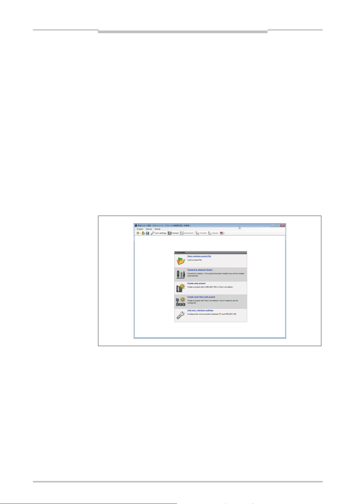
Figure 1:
Start view with selection of
the action
This chapter familiarizes you with the basic elements of the graphical user interface as
an introduction. This chapter does not give any information on the configuration of
MELSEC-WS modules nor any instructions for logic programming. This chapter is only
intended to explain the fundamental functioning of the Setting and Monitoring Tool on
the basis of a small section of the functions. Experienced users of Setting and
Monitoring Tool can skip this chapter.
5.1 Start view
After the Setting and Monitoring Tool has been started, the start view is displayed. The
user can specify here with which of the following actions he wants to start:
Open existing project file
Connect to physical device
Create new project
Create new Flexi Link project
Edit com. Interface settings
5.2 Setting the desired language
Click the flag icon in the menu bar at the far right and select the desired language
version.
26
Page 30
Chapter 5
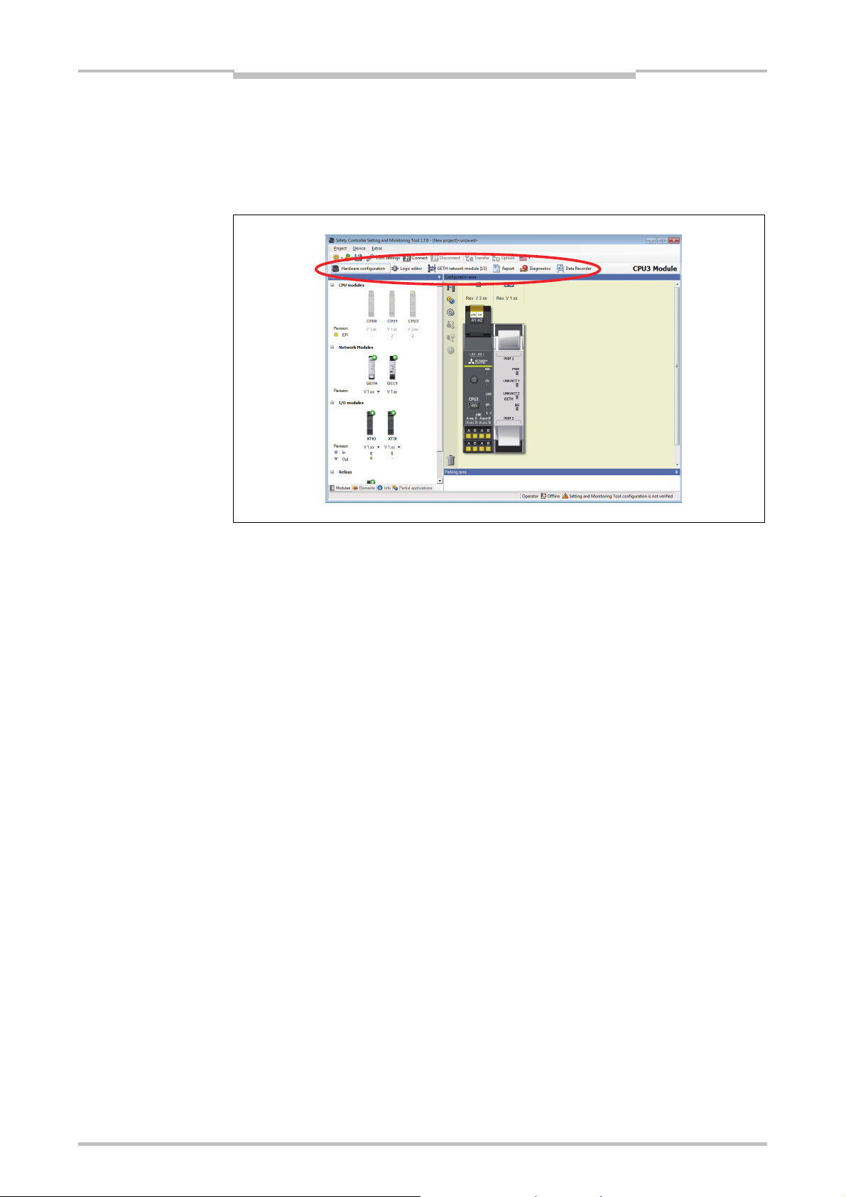
Figure 2:
The view can be selected
below the menu bar
The graphical user interface
5.3 Standard views
The Setting and Monitoring Tool has the following views that can be accessed via
buttons below the menu bar.
Note
The structure of a MELSEC-WS safety controller consisting of various hardware
modules as well as the configuration of the inputs and outputs and the connected
elements are specified in the Hardware configuration view.
The function logic can be configured by means of logic function blocks and
application-specific function blocks in the Logic editor view. This view is not
available unless a CPU module has been selected beforehand in the hardware
configuration.
If the project contains at least one network module or if RS-232 communication is
enabled, the Network module [13] view is available. Here you can configure the
network module and the data that are transferred to and from the network.
Do not save the project data while Setting and Monitoring Tool is connected to the
MELSEC-WS safety controller.
Before saving the project data, disconnect the PC from the MELSEC-WS safety
controller.
Complete information on the currently loaded project and all settings including the
logic programming and wiring diagrams is available in the Report view.
Furthermore, additional information on the project can be entered here. All
information can be saved in standard file formats and printed out. The scope of the
report can be compiled individually depending on the selection.
27
The stored error messages are displayed as a history of a connected MELSEC-WS
safety controller in the Diagnostics view.
Input and output signals from a MELSEC-WS safety controller can be recorded and
displayed inthe Data recorder view.
Page 31

Figure 3:
Sub-windows can be
converted to flyout menus
The graphical user interface
Chapter 5
5.4 Positioning windows
Every view consists of several sub-windows that can be positioned freely. You can
change the height, width and position of each sub-window by using the mouse to
move the frame or title bar of the sub-window,
convert a sub-window into a flyout window by clicking the “Hide” button (drawing pin
symbol) on the right in the title bar. The flyout is then positioned on the left-hand
margin of the Setting and Monitoring Tool window,
move flyout windows back to their normal position by clicking the drawing pin icon in
the flyout window again.
28
Page 32

Chapter 5
The graphical user interface
5.5 Hardware configuration view
The Hardware configuration window consists of the following sub-windows:
Tabs for switching between the Hardware configuration, Logic editor, Network
modules (if the project contains at least one network interface module), Report,
Diagnostics and Data Recoder view.
Menu bar with the menus Project, Device, Extras
Toolbar with icons for rapid access to menus that are often used
Elements selection window: All devices (e.g. sensors, actuators etc.) that can be
connected to a MELSEC-WS safety controller are listed here. The devices can be
parameterized and renamed. In addition, user-defined devices can be created and
stored. In addition to the elements, EFI elements can also be connected. They are
dragged to the two EFI interfaces of the CPU module, provided that the CPU
module provides EFI interfaces.
Partial applications selection window (see section 5.5.9).
Parking area: The user can compile a selection of devices for a concrete
application and store them temporarily here.
Modules selection window: All MELSEC-WS modules that can be combined into a
MELSEC-WS safety controller are listed here. The modules that cannot be selected
at the current configuration are grayed out. Modules that can be added to the
current configuration are identified by a green “+” symbol. The number of inputs,
outputs and EFI connections is displayed for each module.
From a drop down list under the module, the Revision (or function package) for the
respective module can be selected. The function package chosen defines the
minimum firmware version that must be used: Revision 2.XX requires at least
firmware version 2.00. See also Chapter 3.
Configuration area: The entire hardware configuration of the MELSEC-WS safety
controller and of the connected devices is created here and represented graphically.
The individual modules and connected devices can be named, have a tag name
assigned and can be parameterized using the context menu of the devices.
Additionally, it is possible to export or import a configuration (hardware configuration
and logic) and – if the Setting and Monitoring Tool is connected to the system – to
change the password or to perform a software reset of the system via the context
menu of the CPU module.
Icons for the following functions are located on the left next to the positioned modules.
From top: Switch view, Settings and Edit tag names. When a connection to a Flexi
Link station is established, further functions are also available: Log in (change the
user group), Verify (read in and compare the configuration) and Run or Stop the CPU
module.
29
Page 33

The graphical user interface
Chapter 5
Figure 4:
The “Hardware
configuration” view
Figure 5:
Switch view button
Note
A double click on the CPU module in the configuration area will open the logic editor.
A double click on any network module in the configuration area will open the
network module configuration view for the respective network module.
Switch view
Figure 6:
Settings button
The Switch view button toggles between an enlarged and a reduced view of the
configuration area.
Settings
The Settings button opens a dialog where you can adjust the settings for your project.
Here you can …
create your own tag name format,
enable or disable customized elements (see Section 5.5.6),
enable or disable the import of customized function blocks,
enable or disable RS-232 routing for the CPU,
enable additional XT modules (see Section 5.5.1),
save the current view and/or activate a saved view.
change the path for the folders where user defined elements are saved,
export the module status bits as a CSV file, e.g. for use in a Programmable
controller.
30
Page 34

Chapter 5
Figure 7:
Edit tag names button
Figure 8:
Online edit mode button in
the hardware view
The graphical user interface
Edit tag names
The Edit tag names button opens the central Tag name editor (see Section 5.6.10).
Online edit mode button
If you need to change the configuration while the Setting and Monitoring Tool is
connected to the system, you can use the Online edit mode button in the upper right
corner of the screen over the configuration area to switch into the edit mode. This way
it is possible to edit the configuration without disconnecting from the system first.
Exercise
5.5.1 Exercise for configuring the MELSEC-WS modules
Create a new standalone project using the New Project button. All available
MELSEC-WS modules are displayed in the Modules selection window. All modules
are grayed out with the exception of the CPU modules.
Select the function package from the dropdown list under the desired CPU module
(WS0-CPU0, WS0-CPU1 or WS0-CPU3). Function package Revision V 2.xx
requires CPU firmware version 2.01 or higher (see Chapter 3).
Use the mouse to drag the CPU module into the Configuration area. The CPU
module is displayed magnified there. The inputs/outputs and terminals are visible.
The CPU modules are now grayed out and the other modules (network modules,
I/O modules) can be selected in the Modules selection window.
Move further safety I/O modules in the Configuration area. Green arrows indicate
where the new module will be positioned. Grey arrows indicate possible other
positions. The CPU module is always located at the left. Up to two network modules
follow directly to the right of the CPU module. Then the safety I/O modules follow.
The safety relay output modules have to be positioned at the far right.
Right-click the individual modules and select Edit... in the context menu. Enter a
new tag name (module name) for the respective module and close the window by
clicking OK.
Change the positions of the modules subsequently by using the mouse to drag
them to a different position.
31
Remove modules from the configuration area by right-clicking the module and
choosing the Remove module… command in the context menu. Alternatively, you
can use the mouse to drag the module to the trashcan at the bottom left of the
Configuration area.
Page 35

Note
The graphical user interface
Chapter 5
A MELSEC-WS safety controller can contain maximally two network interface
modules.
A MELSEC-WS safety controller can contain maximally twelve I/O modules.
Enable configurations with more than twelve I/O modules
Using Setting and Monitoring Tool version V1.7.0 or higher you can enable
configurations with up to 22 I/O modules. This feature makes it possible for you to
prepare a common maximum configuration for several similar systems and then to
adapt this configuration to the related system by simply deleting modules that are
not required.
For configurations containing more than twelve I/O modules, the following
restrictions apply:
– You can not connect to a system and the configuration can not be transferred to
the MELSEC-WS safety controller.
– Simulation is not possible.
A MELSEC-WS safety controller can only ever contain a maximum of two network
interface modules.
How to enable configurations with more than twelve I/O modules:
In the Hardware configuration view, click on the Settings icon at the left of the
Configuration area to open the Settings dialog.
On the General file card, activate the Enable additional XT modules option.
Click OK.
32
Page 36

Chapter 5
Figure 9:
CPU status bits in the
Hardware configuration view
The graphical user interface
5.5.2 Module status bits in the Hardware configuration view
When the MELSEC-WS safety controller is online (i.e. the Setting and Monitoring Tool
is connected to the system), you can display the status bits of each module and their
current values.
Right click on any module (CPU module, network module or safety I/O module) and
select Edit... in the context menu. If the system is online, the dialog window for the
selected module opens with the additional Diagnostics file card where all available
status bits for the selected module and their values are displayed.
Click on the Refresh button to update the values of the module status bits.
Figure 10:
Network module status bits
in the Hardware
configuration view
33
Page 37

The graphical user interface
Chapter 5
Figure 11:
WS0-XTIO module status
bits in the Hardware
configuration view
Figure 12:
WS0-XTDI module status
bits in the Hardware
configuration view
How to export the module status bits:
In the Hardware configuration view, click on the Settings icon at the left of the
Configuration area to open the Settings dialog.
On the Export module status file card, click on the Export button. A file selection
dialog opens.
Navigate to the folder where you want to save the export file, enter a file name for
the export and click on Save. The module status bits are saved as a CSV file.
34
Page 38

Chapter 5
The graphical user interface
5.5.3 Exercise for configuring the connected devices
Exercise
Note
Note
The selection tree in the Elements selection window can be expanded and
collapsed by means of a mouse click. Optional: Right-click a device and select Edit
current element in the context menu. Assign a user-defined Internal item number
if you want to. This Internal item number is stored for this device.
Select some devices from the list and drag them into the Parking area.
The Parking area serves to increase clarity. You can compile all required devices
here so that you do not forget any of them during the configuration. Alternatively, you
can drag the devices directly from the Elements selection window into the
Configuration area.
Then drag a device from the Parking area into the Configuration area.
If the Configuration area does not contain a module with suitable free
inputs/outputs, the device cannot be placed there. In this case, place at least one
hardware module with inputs or outputs, e.g. WS0-XTIO or WS0-XTDI, in the
Configuration area.
When the device is moved over suitable free inputs or outputs, they light up green.
The Setting and Monitoring Tool automatically considers the required number of
inputs or outputs. Drop the device on a suitable position. The device icon is now
displayed in the view at this point.
Certain elements can not be connected to all modules:
Dual channel elements can only be connected to safe modules.
Pure safety elements can only be connected to safe modules.
Drag the device to other suitable inputs or outputs or back into the Parking area.
Delete the device by right-clicking the device icon and clicking Remove in the
context menu. Alternatively, you can use the mouse to drag the device to the
trashcan at the bottom left of the Configuration area.
A device can be parameterized when it is located in the Parking area or in the
Configuration area. Right-click a device in the Parking area or Configuration
area and select Edit... from the context menu or double-click a device. The
Element settings window is opened. Depending on the type of device you can:
– assign a tag name (identifying name for the element)
– set evaluation parameters for the element, for example the discrepancy time,
ON-OFF filter or OFF-ON filter, connection to a test output, test pulses
enabled/disabled, etc.
(See also Section 5.5.6).
Close the Element settings window by clicking OK.
35
Page 39

The graphical user interface
Chapter 5
5.5.4 Safe and non-safe elements in the hardware configuration
Safe and non-safe elements are shown in the hardware configuration using different
colors:
Safe elements are marked yellow.
Non-safe elements are marked gray.
The majority of elements are only marked as safe or non-safe when they are dragged
to a corresponding input or output:
Safe elements that are dragged to a safe input or output are marked yellow.
If an element marked gray is dragged to a safe input or output, it remains marked
gray but can be marked yellow by editing.
How to mark an element as a safety element:
Double-click a gray or red marked element or click it using the right mouse button
and select Edit... on the context menu. The Element settings window opens.
Activate the Safety element checkbox.
Click on OK to close the Element settings window. The element is now marked
yellow.
5.5.5 Expanding elements
Some elements consist of a group of two or more sub-elements, such as an interlock
that consists of a safety switch as input element and an interlock with locking as output
element. Normally these elements must be connected to one module (e.g. WS0-XTIO),
but some of these elements can be expanded so that the individual sub-elements can
be connected to different modules.
How to expand an element:
Place the element (e.g. an interlock) in the Parking area.
Right click the element to open the context menu.
Select the Expand command. The element in the Parking area is replaced by its
sub-elements which can be treated like individual elements.
36
Page 40

Chapter 5
Figure 13:
Element settings window for
an ES21 emergency stop
button
The graphical user interface
5.5.6 Parameterization of connected elements
Input and output elements can be parameterized when they are located in the Parking
area or in the Configuration area. Depending on the type of element you can:
– assign a tag name (identifying name for the element)
– set evaluation parameters for the element, for example the discrepancy time,
ON-OFF or OFF-ON filter, connection to a test output, test pulses
enabled/disabled, etc.
How to parameterize a connected element:
Double click on the element or right click an element in the Parking area or in the
Configuration area and select Edit... from the context menu. The Element
settings window is opened.
Tag name
Enter a Tag name for the element, if desired. Otherwise the default tag name is
used.
Nr. of devices
Adjust the Nr. of devices, if necessary. E.g. if you have connected a cascade of
several SICK L21 testable type 2 sensors to one input, you can use this function to
adjust the number of devices that will appear on the bill of material in the project
report to match the actual number of devices used.
37
Page 41

Note
ATTENTION
The graphical user interface
Chapter 5
Element is connected to test outputs
By activating or deactivating the option Element is connected to test outputs you
can determine whether the respective element shall be tested or not. By connecting
an element to the test outputs …
short circuits to 24 V in the sensor wiring which could inhibit the switch-off condition
can be detected,
electronic sensors with test inputs (e.g. SICK L21) can be tested.
To activate or deactivate the connection to the test outputs either click on the
checkbox or on the 3D buttons on the right side.
One WS0-XTDI has 2 test sources only, even if it has 8 test output terminals.
Protect single channel inputs against short circuits and cross circuits!
If a stuck-at-high error occurs on a single channel input with test pulses that was
previously Low, the logic may see a pulse for this signal. The stuck-at-high first causes
the signal to become High and then after the error detection time back to Low again.
Due to the error detection a pulse may be generated. Therefore single channel signals
with test pulses need special attention:
If the stuck-at-high occurs on a single channel signal input with test pulses that was
previously High, the logic will see a delayed falling edge (High to Low transition).
If a single channel input is used and an unexpected pulse or a delayed falling edge
(High to Low) at this input may lead to a dangerous situation, the following
measures have to be taken:
– Protected cabling of the related signal (to exclude cross circuits to other signals)
– No cross circuit detection, i.e. no connection to test output.
This needs especially to be considered for the following inputs:
– Reset input on the Reset function block
– Restart input on the Restart function block
– Restart input on the Press function blocks (Eccentric Press Contact, Universal
Press Contact, N-break, Press Setup, Press Single Stroke, Press Automatic)
– Override input on a Muting function block
– Reset input on a Valve function block
– Reset to zero input and Reload input on a Counter function block
38
Page 42

Chapter 5
Figure 14:
Create custom element
template window
The graphical user interface
5.5.7 Customized elements
In addition to the standard input and output elements that are installed with the Setting
and Monitoring Tool, it is possible to create, configure, import and export customized
elements. This function allows you to create element templates with preset
configuration options (e.g. single-channel or dual-channel evaluation, discrepancy
time, on-off filtering, connection to test outputs etc.) that are adapted to your specific
equipment needs.
How to enable customized elements:
In the Hardware configuration view, click on the Settings icon at the left of the
Configuration area to open the Settings dialog.
In the General tab, activate the Enable customized elements option.
Click on OK.
How to create a customized element:
In the Hardware configuration view, right click on any element (in the Elements
window, in the Configuration area or in the Parking area). It is recommended to
choose an element that is as similar as possible to the customized element you
want to create.
From the context menu select the command Save as customized element.... The
Create custom element template window opens.
39
Note
Rename and configure the element as needed (see below for details).
Click on Save to save the new element and close the window.
You have to enter a new name for the template in order to save it.
Make sure that all settings are complete and correct before you save the new
template. It is not possible to change an existing element template within the Setting
and Monitoring Tool, no matter whether it is a standard or a customized template.
Page 43

Figure 15:
Add or delete sub-elements
for a customized element
The graphical user interface
Chapter 5
How to configure a customized element:
Select the new customized element in the element tree and use the sub-element
buttons under the element tree to add additional inputs or outputs. You can choose
between single-channel and various dual-channel input and output types. If you add
sub-elements, these will appear in the element tree one level below the customized
element.
Figure 16:
Entering the BOM info for a
customized element
Select the new element in the element tree and enter a new name for it in the
General file card. It is not possible to save an element with a name that is already
used by another element. However, it is not necessary to enter the new element
name in all languages shown. You only have to change the element name in the
language that is currently set in the Setting and Monitoring Tool on your PC.
Use the Browse... button at the bottom of the screen to assign a custom image to
any element or sub-element.
If an element contains two or more sub-elements, the Extractable? option is
available. Elements based on a template that has been configured with this option
active can be expanded or “split” into their sub-elements which can then be treated
as individual elements (see Section 5.5.5).
If the option Single test output is activated, all sub-elements of the element must
be connected to the same test output. Examples for this are the tested user mode
switches which must use either inputs I1/I3/I5/I7 if test output X1 is used or inputs
I2/I4/I6/I8 with test output X2.
Enter the desired BOM (“bill of material”) information in the BOM info file card for
the used elements and sub-elements. This information will be used in the Setting
and Monitoring Tool report in the material list.
40
Page 44

Chapter 5
Figure 17:
Editing the configuration
settings of a customized
element
Note
Note
The graphical user interface
Select the customized element (or the sub-element) that you want to configure and
click on the Settings file card to edit the configuration settings.
Adjust the settings (e.g. Discrepancy time, ON-OFF filter, OFF-ON filter etc.) as
described in Section 5.5.5. In addition to editing the configuration options, you can
also activate or deactivate them completely and enter maximum, minimum and
preset values.
Check the Mandatory checkbox for a function, if elements based on this template
must be used on modules supporting this function (e.g. to create an element that
requires connection to a module with test outputs).
Check the Element configuration editable checkbox, if Elements based on this
new template shall be editable within the limits that are preset on the Settings file
card.
If only selected individual configuration options shall not be editable, uncheck the
Visible checkbox for these options.
How to transfer a customized element to another PC:
Save the project file and open it on the other PC. Customized elements contained
in the project will be imported automatically.
Importing customized elements requires Setting and Monitoring Tool version 1.3.0 or
higher.
How to delete a customized element:
In the Elements window in the Hardware configuration view, right click on the
customized element you want to delete.
From the context menu select the command Delete template.... You will be asked
for confirmation.
Click OK.
It is not possible to delete a standard element template.
41
Page 45

Note
The graphical user interface
Chapter 5
How to export customized elements as XML files:
In the Elements window, right click on the customized element you want to export
and choose the Export... command from the context menu. A folder selection
dialog opens.
Select or create the folder where you want to save the customized element and
click on OK. The customized element is then saved as an XML file.
How to import customized elements as XML files:
In the Elements window, right click on any element or element group and choose
the Import... command from the context menu. A file selection dialog opens.
Select the XML file for the customized element that you want to import and click on
Open. The customized element will be imported.
5.5.8 Connection of SICK EFI-compatible devices
You can connect SICK EFI-compatible devices to your CPU module if your project
contains a WS0-CPU1 or WS0-CPU3.
Drag and drop the desired SICK EFI-compatible device (e.g. a C4000 safety light
curtain) from the Elements selection window to the EFI connection of the CPU
module. The Device selection wizard will open where you can select the exact
device variant or enter its type code directly.
Click Finish to confirm your selection and to connect the selected SICK EFI-
compatible device. The EFI bits for the connected SICK EFI-compatible device are
now available in the logic editor as inputs and outputs for the CPU.
Double-click an SICK EFI-compatible device to open its configuration dialog.
The configuration of an SICK EFI-compatible device must be uploaded or
transferred separately in the configuration dialog of the SICK EFI-compatible device.
To do this, you have to connect the Setting and Monitoring Tool with the MELSEC-
WS safety controller first.
Note
For details of the SICK products, please contact your local SICK representative
(see Section 15.4).
www.sens-control.com
Depending on the devices already connected there may be restrictions which
devices can be connected on the other EFI connection.
Switching of the EFI address
In some combinations of SICK EFI-compatible devices it is mandatory that the
MELSEC-WS safety controller has the EFI address 13, because EFI address 14 is
already occupied by another SICK EFI-compatible device (e.g. EFI network module,
UE403).
To switch between EFI address 13 and 14, right click on the WS0-CPU1 or WS0-
CPU3 and choose Address 13 or Address 14 from the context menu.
After switching of the EFI address, the MELSEC-WS safety controller carries out a
reset, i.e. all outputs are switched off.
42
Page 46

Chapter 5
The graphical user interface
EFI system integrity test
The WS0-CPU1 or WS0-CPU3 can test the SICK EFI-compatible devices connected
to the EFI interfaces at every voltage reset. The following parameters can be
compared with the parameters saved the last time the CPU module was configured:
Type code: A device with the same type code is expected.
Serial number: A device with the same serial number is expected.
Configuration data: A device with the same configuration data is expected.
If the parameters of the connected device do not match, the WS0-CPU1 or WS0CPU3 will use 0 for the input and output data of this EFI device and the corresponding
EFI LED (EFI1 or EFI2) will start flashing
Red (1 Hz).
Figure 18:
Configuration of the EFI
integrity test
Note
If the configuration data is used for the EFI system integrity test, then it is imperative to
transfer the configuration of the connected SICK EFI-compatible devices before the
configuration of the CPU module is transferred.
If the configuration does not match the devices actually physically present a question
mark is displayed in the hardware configuration in Setting and Monitoring Tool at the
related EFI connection.
An EFI-compatible device is physically present on this EFI connection but not in the
configuration of the CPU module. If you now upload the configuration using the
Transfer project command, this device will be added to the configuration of the CPU
module. Exception: If the configuration in the CPU module is verified, the sensor is
not corrected. In this case the configuration in the CPU module remains unchanged.
An EFI-compatible device is configured on this EFI connection, but is not present
physically. In this case the icon for the device is displayed with a question mark. If
you now upload the configuration using the Transfer project command, this device
will be removed from the configuration of the CPU module. Exception: If the
configuration in the CPU module is verified, the sensor is not corrected. In this case
the configuration remains unchanged.
How to configure the EFI system integrity test:
If the Setting and Monitoring Tool is connected to the WS0-CPU1 or WS0-CPU3,
click on Disconnect or change to the Edit mode.
Right click on the CPU module and select the Edit... command from the context
menu. In the following dialog, click on the EFI button on the left side.
43
Check all parameters that shall be used for the EFI system integrity test.
Click OK to accept the settings and to close the dialog.
Page 47

Note
The graphical user interface
Chapter 5
5.5.9 Export and import of a partial application
You can export or import a partial application. All modules with their associated inputs
and outputs and logic are exported except for the WS0-CPU0/WS0-CPU1/WS0-CPU3.
If you are exporting a project containing SICK EFI-compatible devices have to be
reconfigured when you import the configuration into another project.
When you import a partial application into an existing project, the stored modules,
elements and logic are added to the project while the rest of the project remains
unchanged. This is especially useful if you need to replace a CPU in an existing
project without re-configuring the entire hardware and logic.
Tag names of CPU markers, logic results, EFI1/EFI2, and RS-232 I/O cannot be
exported. (For example, when an exported CPU marker with a tag name is imported to
another project, the tag name is not reflected. A tag name configured in the importtarget project is displayed. If no tag name is configured in the import-target project, no
name is displayed.)
Among the outputs in the logic editor, CPU output markers, logic results, and
EFI1/EFI2 are imported only when they are not used in the import-target project.
How to export a partial application:
In the Partial applications selection window, click on Save as new partial
application.
Figure 19:
Export configuration dialog
Or:
Right click on the CPU module and select the Export configuration... command
from the context menu. The following dialog opens.
You can add a description of the partial application in the Description field.
Click on the button on the right of the Export file field. A file selection dialog opens.
Navigate to the folder where you want to save the export file, enter a file name for
the export and click on Save to close the file selection dialog again.
Click OK to export the partial application.
44
Page 48

Chapter 5
Figure 20:
Import configuration dialog
The graphical user interface
How to import a partial application
In the Partial applications selection window, click on Load partial application.
Or:
Right click on the CPU module and select the Import configuration... command
from the context menu. The following dialog opens.
Click on the button on the right of the Import file field. A file selection dialog opens.
Select any fsi file and click OPEN to display the contained partial application and
description in the panel.
Click OK to import the selected partial application. The hardware in the import file
will be added to your projects hardware configuration while the imported logic will
be inserted as one or several new separate pages in the Logic editor.
Example: A project contains a WS0-CPU1 and an WS0-XTIO module, a C4000, an
emergency stop button, a robot and one page with the necessary logic in the logic
editor. The partial application to be imported contains another WS0-XTIO module
with a two hand control and a motor plus one logic editor page with the logic for
controlling these devices. After the import has been completed, the project will
contain both WS0-XTIO modules with the respective devices connected and both
logic programs on two separate pages.
How to exchange a CPU module in a project:
Using the export and import function, it is possible to exchange a CPU module (e.g.
WS0-CPU0 to WS0-CPU1 or another firmware version (from Ver.1 to Ver.1.xx or
later)) in an existing project without having to re-configure the project (hardware
configuration, logic).
Load the project with the CPU module you want to exchange.
Export the partial application as described above.
In the Project menu, select the command New, Standalone station project.
In the Hardware configuration view, add the desired new CPU module to the new
project.
Right click on the new CPU module and reimport the partial application.
45
Page 49

The graphical user interface
Chapter 5
Note
Note
The configuration of any connected SICK EFI-compatible devices is not included in
the exported partial application. Therefore these devices have to be reconfigured.
How to exchange a safety I/O module in a project:
Load the project with the safety I/O module you want to exchange.
Add the desired new safety I/O module to the hardware configuration.
Move the connected elements from the old module to the new module. This way the
logic connections will be preserved.
Delete the old module.
This method does not work for elements that are used in combination with a Fast
shut off function block, because these elements can not be moved to another
module anymore.
This method does not work either for grouped elements like e.g. operating mode
selector switches and switches with interlock.
46
Page 50

Chapter 5
ATTENTION
Figure 21:
Activating RS-232 routing
The graphical user interface
5.5.10 RS-232 routing
You can access the input and output data on the MELSEC-WS safety controller via
the RS-232 interface on the CPU. This feature makes possible, e.g., communication
between the MELSEC-WS safety controller and a Programmable controller connected
without using a network interface module or the connection of an HMI.
Do not use the RS-232 interface for safety-related applications!
The communication protocol used for the RS-232 interface does not support any
safety mechanisms necessary for communication in a safety network.
For this reason the data exchanged via the RS-232 interface are not allowed to be
used for safetyrelated functions.
How to activate the RS-232 routing:
In the hardware configuration, click the Settings button in the left of the
configuration area.
On the General tab, select the Enable RS-232 routing for the CPU option.
47
Click OK. The RS-232 routing is then activated. On the Interfaces menu you can
now open the configuration window for the data to be transferred.
You can read up to 100 bytes from the MELSEC-WS safety controller and write up to
4 bytes to the MELSEC-WS safety controller.
Page 51

Figure 22:
Configuration of the
operating data transferred
via RS-232 to the network
The graphical user interface
Chapter 5
Configuration of the input data for the RS-232 routing
On the Interfaces menu, click RS-232 [0] to open the dialog box for the RS-232
configuration.
Click the MELSEC-WS to RS-232 button on the left to display the routing
configuration for the input data.
Figure 23:
Toolbar for the routing
configuration
Note
Basically this dialog is divided into three areas: Available data 1), RS-232 data 2) and
Tag names 3). The upper left corner of the dialog holds the toolbar 4).
The toolbar
The toolbar contains buttons for the following actions (from left to right):
The Load user configuration and Save user configuration buttons allow you to
load and/or save a configuration in XML format, including the used tag names. If
you load a configuration, all previously made changes that have not been saved will
be lost. You can not undo this action.
Using the Import and Export buttons you can import and export the tag names
used as a CSV file (comma separated values). This allows you to import and use
the assigned tag names in a Programmable controller program.
The Import button is only available for the RS-232 to MELSEC-WS routing
configuration.
48
Page 52

Chapter 5
The graphical user interface
Reset to default restores the default routing configuration. You will be asked for
confirmation. If you click Yes, all previously made changes that have not been
saved will be lost. You can not undo this action.
Clear all clears the configuration, i.e. deletes all assigned bytes in the RS-232 data
area. You will be asked for confirmation.
Delete routing deletes the currently selected byte in the RS-232 data area.
The Undo and Redo buttons allow you to undo or redo changes you made to your
configuration.
Available data
This area offers all sources from which data may be routed into the network. It is
divided in two views holding the available input and output data. You can switch
between these views using the file cards at the bottom.
The Input view contains the input values for the connected MELSEC-WS modules
and EFI devices as well as the module status data. If your MELSEC-WS safety
controller contains network interface modules, the input data on the network
interface modules (i.e. the data the network interface modules receive from the
network) are also available here.
The Output view offers the output values for the connected MELSEC-WS modules
and EFI devices as well as the Logic results from the logic editor.
All sources supported by the current configuration are displayed in black:
connected MELSEC-WS modules
connected EFI devices
*1
configured logic results
gateway input data and gateway output data
Sources currently not configured will be displayed in grey. Activating the Show only
available data checkbox in the upper left corner hides the unused sources from the
view.
Sources that are used in the logic program are marked with a small symbol beside the
text.
*1 In the default configuration, only the first logic result byte (Logic Result 0) is active and available. You
can activate more output bits for logic results in the logic editor.
How to add a data byte to the routing table:
Drag and drop an element (i.e. byte) from the Available data area to a free slot in
the Gateway data set to network area. If the desired position is not free, you will
have to clear it first by deleting or moving the byte currently assigned to it.
It is possible to use the same byte several times in the routing table.
49
RS-232 data area
This area contains the routing table. It shows the actual contents of the data sent via
the RS-232 interface. Bytes and bits highlighted in blue contain “live” system data if
the hardware configuration supports the source. Bytes highlighted grey actually do not
have data associated with them since the hardware configuration does not support the
sources.
Page 53

Figure 24:
RS-232 to MELSEC-WS
dialog
The graphical user interface
Chapter 5
How to delete a data byte from the routing table:
Drag and drop the byte you want to delete to the trashcan icon in the bottom left
corner of the RS-232 data area.
Or:
Select the byte you want to delete by clicking it with the left mouse button. Then,
click on the Delete routing button in the toolbar.
Or:
Call up the context menu by clicking the respective byte with the right mouse button.
In the context menu, select the Delete routing command.
How to move a data byte to another place in the routing table:
Drag and drop the byte you want to move to the desired position. If the desired
position is not free, you will have to clear it first by deleting or moving the byte
currently assigned to it.
Tag names area
This area shows the tag names for all bits in the byte currently selected in the
Available data area or in the RS-232 data area. You can edit the tag names in the
tag name editor and also to some extent in the logic editor and in the hardware
configuration dialog box (e.g. for expansion modules). In the Tag names area of the
MELSEC-WS to RS-232 configuration dialog, it is not possible to edit the tag names.
Configuration of the output data (RS-232 to MELSEC-WS)
Click the RS-232 to MELSEC-WS button on the left. The following dialog will be
displayed.
Basically this dialog is divided into two areas: RS-232 data 1) and Tag names 2):
The RS-232 data area shows the current configuration of the output data.
50
Page 54

Chapter 5
Figure 25:
Tag names for the RS-232
output data in the logic
editor
The graphical user interface
The Tag names area shows the tag names associated to the byte selected in the RS232 data area.
Choose a byte in the RS-232 data area.
For each bit of the selected byte that you wish to use, enter a tag name.
Each bit to which you assign a tag name here is then available as an RS-232 input in
the logic editor.
Note
Saving and loading a configuration
Using the buttons Load user configuration and Save user configuration you can
save or load a configuration in XML format. If you load a configuration, all previously
made changes that have not been saved will be lost. You can not undo this action.
Importing and exporting a configuration
Using the Import and Export buttons you can import and export a configuration
including the tag names used as a CSV file (comma separated values). This allows
you to import and use tag names you have assigned in the MELSEC-WS project in
the Programmable controller program and vice versa.
If you import a configuration, all previously made changes that have not been saved
will be lost. You can not undo this action.
The Import button is only available for the RS-232 to MELSEC-WS routing
configuration.
51
Page 55

Figure 26:
The logic editor
The graphical user interface
Chapter 5
5.6 Logic editor view
The Setting and Monitoring Tool includes a graphical Logic editor. The function logic
is program-med by using logic and application-specific function blocks. The inputs,
function blocks and outputs are positioned on a worksheet and are connected
correspondingly.
As soon as a MELSEC-WS CPU module is located in the Configuration area, the
Logic editor can be accessed via the tab of the same name.
The Logic editor window consists of the following sub-windows:
Menu bar with the menus Project, Device, Extras
Toolbar with icons for rapid access to menus that are often used
Tabs for switching between the Hardware configuration, Logic editor, Network
module [13] (if the project contains at least one network module), Report,
Diagnostics and Data Recorder view.
Specific toolbar for the logic editor with the following functions:
Add/Delete/Rename page, Print current page, Zoom, Copy/Cut/Paste/Delete
elements, Undo/Redo last action, Open dialog to edit logic result markers,
Show/Hide grid, Show grid of lines/dots, Show function block I/O description,
Search function block, Start simulation mode and Start forcing mode
Selection windows for Function block, Inputs, Outputs and Diagnostic inputs
FB preview window on the bottom left for displaying the important system
resources such as the number of used/available function blocks or the current logic
execution time (cycle time of the logic). When the cursor is moved over a function
block in the worksheet, additional information on this function block is displayed in
the FB preview window.
Worksheets (Pages) for creating the logic, I/O summary page and I/O matrix that
can be selected alternatively by using tabs
52
Page 56

Chapter 5
The graphical user interface
5.6.1 Exercise for using the logic editor
Exercise
Note
In the Hardware configuration view combine a CPU module, at least one
WS0-XTIO module and one element.
Switch to the Logic editor by clicking the tab of the same name.
In the selection window for Inputs, Function block and Outputs, click Inputs and
drag an input from the list onto the worksheet. You can mark several inputs if you
click them while holding down the Ctrl key or if you click the first and last in a
series while holding down the Shift key. Then you can drag all marked inputs to
the worksheet simultaneously.
In the selection window for Inputs, Function block and Outputs, click Function
block and drag an application-specific or logic function block from the list onto the
worksheet. The function block will be displayed orange while not all of its inputs
have been connected.
In the selection window for Inputs, Function block and Outputs click Outputs and
drag an output from the list onto the worksheet.
The inputs and outputs are marked in color in the logic editor depending on their
function:
– gray: non-safe
– yellow: safe
– blue: diagnostics
Connect the node of the input with an input field of the function block (node) and an
output (node) of the function block with the node of the output. To do so, click one
node with the left mouse button, hold the left mouse button pressed and drag the
cursor to the node with which the first node is to be connected. Once all inputs of
the function block have been connected, the function block is displayed yellow.
Alternatively it is possible to place and connect inputs or outputs in one step. Drag
an input or output while keeping the left mouse button pressed to the desired
function block input or output node. If the mouse pointer hovers over the node it will
be highlighted. Then drag the input or output to the place on the worksheet where it
shall be positioned and release the left mouse button.
While holding down the Ctrl key you can drag and drop the end of an already
existing connection line from one node to another. This is useful to reassign a
connection without having to delete it first.
Mark the input, function block, output and the connections by clicking them or by
dragging with the left mouse button pressed and then position as desired.
In the selection window for Inputs, Function block and Outputs, click FB preview.
A preview of the respective element or the details of a function block are displayed
in the FB preview window when you move the cursor over it.
To replace one function block with another function block, drag the required function
block from the selection list over a function block already positioned until the
existing function block is highlighted green, and then release the left mouse button.
You are prompted as to whether you want to replace the function block positioned
previously with the new function block.
Using the right mouse button, click an input or output element in the logic editor to
show the logic pages on which the element clicked is used.
In order to delete an element from the worksheet, right-click it and select the
Delete command from the context menu.
53
Page 57

Table 4:
Access levels in the logic
editor
The graphical user interface
Chapter 5
5.6.2 Logic access levels
The logic access levels function allows you to protect individual pages in the logic
editor using a password. You can prevent changes to the logic page by
unauthorized persons.
There are the following logic access levels:
Access level Right
Not logged
Edit unprotected pages
Logic access level 1
Logic access level 2
Edit unprotected pages
Edit protected pages (only access level 1)
Set up page protection for unprotected pages (only
access level 1)
Remove page protection for pages (only access level
1)
Edit unprotected pages
Edit all protected pages
Set up page protection
Remove page protection from all pages
Disable page protection
How to activate page protection:
In the hardware configuration, right click on the CPU module and select the
Change in access for Logic pages command from the context menu.
Activate the Enable password protection for Logic pages option.
Enter passwords for the logic access levels 1 and 2.
Click OK.
How to log in for a logic access level:
In the hardware configuration, right click on the CPU module and select the
Change in access for Logic pages command from the context menu.
In the Current User Level area, click on Log in.
In the Log-in dialog box select the logic access level for which you want to log in,
type the password and click Log in.
Click OK.
How to log off:
In the hardware configuration, right click on the CPU module and select the
Change in access for Logic pages command from the context menu.
In the Current User Level area, click on Log off.
Click OK.
How to protect a logic page:
Open the page to protect in the logic editor.
Using the right mouse button, click the page and, on the context menu, select the
required logic access level on the Set up access protection for Logic page
submenu.
If you are not logged in, you will now also be prompted to enter the password for
the required logic access level. Enter the password and click on Log in.
54
Page 58

Chapter 5
Figure 27:
Invalid configuration
warnings
The graphical user interface
The logic access level for a protected page is displayed at the top left of the page in
a light-gray font.
How to remove the page protection from a logic page:
In the logic editor open the page on which you want to remove the protection.
Using the right mouse button, click the page and, on the context menu, select on
the Set up access protection for Logic page submenu the Remove access
protection for Logic pages command.
If you are not logged in, you will now also be prompted to enter the password for
the required logic access level. Enter the password and click on Log in.
5.6.3 Validation of the configuration
The Setting and Monitoring Tool performs an automatical check of the logic program.
If an error is detected, the configuration is marked as invalid and a warning icon
appears in the upper right corner of the screen. Additionally, a warning icon marks the
erroneous page of the logic program and the function block that is not connected
correctly (e.g. one or more inputs are not connected) is displayed orange.
ATTENTION
As long as the configuration is invalid, it is not possible to start the simulation mode or
to transfer the configuration to the MELSEC-WS safety controller.
How to correct an invalid configuration:
Connect all unconnected function block inputs. As soon as all function blocks are
connected correctly, they will be displayed yellow and the invalid warnings will
disappear.
Check your application thoroughly for correctness!
The Setting and Monitoring Tool checks only for connection errors in your logic
program. You are responsible to check whether your application conforms to your risk
analysis and avoidance strategy and also fulfils all applicable standards and
regulations. Otherwise the operator of the machine will be in danger.
55
Page 59

Note
The graphical user interface
Chapter 5
5.6.4 Inputs and diagnostics bits of the main module in the logic editor
On the Inputs and Diagnostics tabs in the logic editor, the main module provides the
following inputs and diagnostic bits:
Logical 0 and Logical 1
The Logical 0 input can be used to set a function block input permanently to 0 (Low).
Respectively the Logical 1 input can be used to set a function block input
permanently to 1 (High). This may be necessary to achieve a valid logic
configuration if there are function block inputs that are not used but can not be
disabled.
Configuration is valid
This diagnostics bit is high if the configuration on the main module is valid.
Module power supply is OK
This diagnostic bit is high if there is no error on the supply voltage for the main
module.
Flexi Line Teaching required
This diagnostics bit is high if it is necessary to teach a Flexi Line system.
Verify status
This input is High if the configuration is verified (CV LED of the CPU module is static
yellow on).
First logic cycle
This input is High for the very first logic cycle after every transition from the Stop state
to the Run state. For all following logic cycles it remains Low. This input can be useful
to trigger initialization functions in the logic program.
Simulation bit
You can be set this bit to 0 (Low) or 1 (High) in simulation mode or force mode.
Otherwise the bit is always 0. (This bit is only available with a CPU module with
firmware version V.3.02 and higher and Setting and Monitoring Tool version 1.7.0 or
higher.)
Flexi Link status bits
In a Flexi Link system additional CPU status bits are available. For a description of
these status bits see Section 7.4.7.
Status EFI1 and Status EFI2
These inputs are available only with CPU modules with an EFI interface, e.g. WS0CPU1 or WS0-CPU3. You will find Status EFI1 and Status EFI2 as well as the
equivalent EFI1 is OK and EFI2 is OK on the Diagnostics tab under the main module.
The inputs are set to Low as default.
The input is set to High if …
EFI input and output process data exchange to all EFI devices that are expected
according to the configuration for the EFI interfaces (EFI1, EFI2) is started and
faultless, or
no EFI devices are expected according to the configuration.
The input is set to Low again if an error is detected at the EFI input/output process
data exchange to any of the EFI devices (e.g. communication interruption).
56
Page 60

Chapter 5
The graphical user interface
Note
Table 5:
Meaning of the EFI I/O error
status bits
With AOPD senders there is no EFI process data exchange. Therefore a
communication error will not occur with these devices, i.e. a communication
interruption can not be detected.
5.6.5 EFI I/O error status bits in the logic editor
An I/O error status bit for each connected SICK EFI-compatible device or Flexi Link
station is available in the Inputs tab of the Logic editor under the respective SICK
EFI-compatible device or Flexi Link station and can be used as input for the logic
programming. The I/O error status bit is High if the data or process image of the
connected SICK EFI-compatible device or Flexi Link station is set to Low. This may be
the case e.g. if an error has been detected or if the Flexi Link station is in the Stop
state or being reconfigured.
Status bit Value Meaning
I/O error Low The corresponding SICK EFI-compatible device or Flexi Link
station is error-free (e.g. in the Run state).
High The process image of the corresponding SICK EFI-compatible
device or Flexi Link station is set to Low due to one of the
following reasons:
Error detected on the SICK EFI-compatible device
The Flexi Link station is not in the Run state.
Table 6:
Meaning of the module
status bits
Suspended Flexi Link station has been found.
Flexi Link station with different Flexi Link ID found
See also Section 7.4.7.
5.6.6 Module input and output status bits in the logic editor
The input and output status of the connected network modules and safety I/O modules
is available in the Diagnostics tab of the logic editor and can be used as input for the
logic programming. In some applications an evaluation of this status information can
be important in order to specify the behaviour of the logic functions of the safety
controller. The input status specifies whether the data transferred from the input
device to the CPU module are:
Low, because this is the output value at the input device or
Low, because there is a fault at the input device.
Status bit Value Meaning
Status input
data
Status output
data
Low One or more input bits of the corresponding module are set to Low
due to an detected error (e.g. cross-circuit detected or
communication failure detected), meaning that the input bits may
have different values as in error-free operation.
High The inputs of the corresponding module are error-free.
Low For one or more outputs of the corresponding module an error has
been detected (e.g. overload detected, short circuit detected or
communication failure detected), meaning that the outputs may
have different values as in error-free operation.
High The outputs of the corresponding module are error-free.
57
Page 61

Note
ATTENTION
Figure 28:
Example for the usage of a
CPU marker
The graphical user interface
Chapter 5
The input and output status for the WS0-XTIO and WS0-XTDI modules is available
only with firmware version V2.00 and higher.
5.6.7 CPU markers
CPU markers are available as inputs and outputs in the Logic editor. They can be
used e.g. for the creation of logic loop backs or to connect an output of a function
block that is placed on one page of the logic editor to an input of a function block on
another page of the logic editor.
A CPU marker consists of an output marker and an input marker. The input marker
always takes the same value (High or Low) as the corresponding output marker with a
delay of one logic execution time.
Take the delay caused by CPU markers into account!
CPU markers always cause a delay of one logic execution time, because the input
marker always uses the value of the output marker in the previous logic cycle. The
resulting delay must be considered for the response time calculation and for the
functionality.
How to use a CPU marker:
Connect a CPU output marker (e.g. Marker 0.0) from the Outputs tab of the logic
editor to the function block output that you want to use. Each CPU output marker
can be used only once in a project.
Connect the corresponding CPU input marker (e.g. Marker 0.0) from the Inputs tab
of the logic editor to the function block input where you want to use the signal from
the first function block as shown in the following screenshot. CPU input markers
can be used several times in a project.
58
Page 62

Chapter 5
ATTENTION
Figure 29:
Example of jump addresses
with and without loop back
The graphical user interface
5.6.8 Jump addresses
Jump addresses can be used basically in the same way as CPU markers. They
consist of a source jump address and a destination jump address. The destination
jump address takes the same value (High or Low) as the corresponding source jump
address without delay – provided that it is not a loop back. In this way, jump addresses
differ from CPU markers.
Take logic loop backs into account!
A logic loop back is created if a function block input is connected to a destination jump
address and the related source jump address is connected to an output of the same
function block or to an output of another function block that has a higher function block
index (the function block index is displayed at the top of each function block and
shows the function block’s position in the logic execution sequence). In this case, the
logic result from the current logic cycle is only available at the destination jump
address in the following logic cycle, i.e. with a delay of the logic execution time. If a
jump address causes a loop back, this is indicated automatically by an additional clock
symbol shown on the destination jump address icon. The resulting delay is equal to
the execution time and must be considered for the response time calculation and for
the functionality.
How to use a jump address:
First add a source jump address per drag & drop to your project. A dialog opens
where you must enter a label for the new source jump address. Each source jump
address label must be unique and can be used only once in a project. Typically, a
source jump address is connected to any function block output.
Then add one or several destination jump addresses per drag & drop. A dialog
opens, where you can select the correspondent source jump address for the new
destination jump address from the list of existing source jump address labels. A
source jump address can have several destination jump addresses in a project.
Typically, a destination jump address is connected to any function block input.
59
Page 63

Figure 30:
I/O matrix in offline mode
The graphical user interface
Chapter 5
5.6.9 I/O matrix
The logic editor’s I/O matrix file card displays which inputs have an effect on which
outputs. This can be useful to check whether your logic program is complete.
A green field indicates that the respective input has an effect on the respective output;
a white field indicates that there is no relation between this input and output.
Figure 31:
I/O matrix in simulation
mode
In the I/O matrix window, all inputs and outputs are listed. By checking or unchecking
the checkboxes you can select which inputs and outputs shall be displayed in the I/O
matrix. This can be useful in complex projects with many inputs and outputs to
condense the displayed information to the most important aspects.
I/O matrix in simulation mode
In simulation mode (see Section 9.14), the I/O matrix displays the values of the used
inputs and outputs. High inputs and outputs are displayed green. By clicking on an
input you can toggle its value between High and Low and monitor the effect on the
output values.
60
Page 64

Chapter 5
Figure 32:
Tag name editor
The graphical user interface
5.6.10 Tag name editor
The Tag name editor is the central place where you can edit all tag names in your
project. To open the tag name editor either click on the Edit tag names button in the
Hardware configuration view or click on the Open dialog to edit logic result
markers button in the Logic editor toolbar.
The different types of tag names in the name editor
– Logic results and markers: Tag names in the logic editor (CPU module)
– Local I/O: Input and output element tag names in the hardware view (safety I/O
modules)
– Network module at address 13/14: Input and output data set tag names
(network modules)
– EFI1/EFI2: Input and output tag names for devices on EFI interface 1 and 2
– RS232 HMI: RS-232 I/O tag names
The tag names of the selected type are listed in a tree view on the right side of the
screen.
If a device type is not available in your project (e.g. no SICK EFI-compatible device
connected), then the corresponding section is displayed grey, i.e. inactive.
How to edit the tag names:
Click on one of the active sections on the left side to choose the device type whose
tag names you want to edit:
Navigate through the tree view on the right side to select the bit whose tag name
you want to edit and enter the desired name in the input field.
61
Page 65

Table 7:
Buttons for exporting and
importing tag names
The graphical user interface
Chapter 5
5.6.11 Import and export tag names
With the aid of the Import tag names and Export tag names buttons at the top left
of this window you can save the tag names as a text file in the CSV format (comma
separated values) or import tag names from a CSV file or Excel file.
Symbol Meaning
Import tag names
Export tag names
62
Page 66

Chapter 5
Figure 33:
Report view
The graphical user interface
5.7 Report view
In the Report view, a comprehensive report on the current project and all
configuration settings including the logic program and detailed wiring information is
available. You can individually configure the contents of the report.
Note
The information to be summarized in the report can be selected individually from an
expandable selection list on the left-hand side. The selection is made by activating or
deactivating the check boxes.
The toolbar in the Report view contains the following commands:
Save: Stores the report in PDF format on a data medium.
Print: Open the report in PDF format. To this purpose, a PDF viewer (e.g. Acrobat
Reader Ver.10.0 or later) must be installed on your computer.
Refresh report: Updates the report after changing the report structure.
Change report structure: Switches between a hardware oriented and a function
oriented report structure.
Detailed information on using the wiring information at the end of the report is
available in the Safety Controller User's Manual.
You will find example application reports in the annex of this manual (see Section 15.1).
Exercise for the Report view
Open the Report view by clicking on the Report button.
Use the Change report structure button to choose one of the two different report
structures (hardware- or function-oriented).
Activate or deactivate the check boxes for the components that shall be included in
the report in the selection list on the left-hand side.
After you have completed your selection, click Refresh report. The report is now
assembled and displayed in the right-hand window section.
How to save or print a report:
The report can be printed or saved as PDF.
To save the report as PDF, click on the Save button.
To print the report, click on the Print button. A PDF preview of the report will be
created that you can subsequently print.
63
Page 67

Figure 34:
Diagnostics view
The graphical user interface
Chapter 5
5.8 Diagnostics view
Once you have completed your project and connected to your MELSEC-WS safety
controller, you can perform a diagnostics on your system. In the Diagnostics view, a
complete history of all messages, information, warnings and error messages of a
connected MELSEC-WS safety controller is available in the upper part of the window.
If you click on one of the entries in the list, details on the selected message are
displayed in the lower part of the window.
Table 8:
Meaning of the diagnostics
information
Note
Keyword Description
Code Hexadecimal error code
Description Error description
Time stamp Total CPU module operation time at the time of error (days:hours:min:sec)
Local time Time when error occurred (PC system time).
This value is not displayed for historical errors.
Cycle power Total number of times the CPU module has been switched on
Type Error type (e.g. information, warning, recoverable error, critical error)
Source Module that detected the error
Category Part of the module that detected the error
Information Internal information about the error
Occurrence
counter
Power on hour Total time since the last power-on of the CPU module. This value is reset at
Operating hours Total power-on time of the CPU module
Block Diagnostics memory area in the CPU module.
Register Index in the diagnostics memory area
CPU channel Internal hardware channel (A or B) of the module that detected the error
Number of times this error has occurred.
If an error occurs several times in a row, only the last occurrence will be
recorded and the occurrence counter is increased.
every restart.
8 = RAM (volatile, error occurred within the current power-on cycle)
88 = EEPROM (non-volatile, error occured in a previous power-on cycle)
For a list of the most important error codes, possible causes and potential rectification
measures please see the Safety Controller User's Manual.
64
Page 68

Chapter 5
Figure 35:
Toolbar in the diagnostics
view
Figure 36:
Filtering the diagnostics
messages
The graphical user interface
How to perform diagnostics:
Click on the Diagnostics button in the menu bar to open the Diagnostics view. In
the toolbar, the following commands are available:
Click on Refresh to read the current message list from the system.
Using the Clear button you can delete all messages stored in the system. You must
be logged in as Administrator.
Under Settings you can configure an automatic refresh of the diagnostics and the
time interval. In the Diagnostic Settings dialog, activate the Automatic Refresh
checkbox and enter the desired refresh interval in seconds.
Using the Show history button, you can display or hide older messages still stored
in the MELSEC-WS safety controller.
The Filter pull-down menu enables you to display or hide different types of
messages. In the menu, click on the different message types to activate or
deactivate them.
Note
Note
To save or print the diagnostic messages you can use the Report function (see
Section 5.7).
Change the safety controller to the Stop state before clearing the diagnostic results.
65
Page 69

Figure 37:
Data recorder view
The graphical user interface
Chapter 5
5.9 Data recorder view
Once you have completed your project and established a connection to your
MELSEC-WS safety controller, you can record input and output signals. Various
selection windows area available in the Data recorder view for this purpose.
The Data recorder view contains the following windows and elements:
Selection window for the Trigger and trace configuration: You can record data
either continuously or only once a specific trigger condition is met.
Status/control selection window: Is used to start and stop the recording. In
addition, the data recorder configuration can be read from the device or
transferred to the device here.
Selection windows for the Inputs or Outputs on which the signals are to be
recorded. For this purpose drag the required inputs and outputs from the selection
window to the data display window.
Data display window 1) where the signals recorded on the inputs and outputs are
displayed.
Toolbar with icons to import, export and delete the data recorded, to increase or
reduce the size of the view, or to reset it to its original size. In addition, you can
show and hide markers using the toolbar. You can use the markers, e.g. to
determine the intervals between signal changes.
Recording data
To record data the data recorder configuration in the device and in Setting and
Monitoring Tool must match. With the aid of the buttons in the Status/control
selection window you can transfer the data recorder configuration either from Setting
and Monitoring Tool to the device or read it from the device.
66
Page 70

Chapter 5
The graphical user interface
If you have loaded the configuration from the device into Setting and Monitoring Tool,
you can then start the recording using the Start recording button in the
Status/control selection window.
For this purpose Setting and Monitoring Tool must be connected to the device.
You can also prepare a dedicated data recorder configuration that can then be
transferred to the device. For this purpose drag the inputs and outputs with the signals
to be recorded from the Inputs/Outputs selection window to the data display window.
You can then define in the Trigger and trace configuration selection window when
the data recording is to start:
Continuous: The recording starts immediately after you click the Start recording
button.
Trigger: After you have clicked the Start recording button the recording only
starts once the trigger condition you have defined is met. For this purpose select
one of the inputs or outputs used from the list as a Trigger channel and define
the trigger condition, i.e. whether the recording is to start when the selected
trigger channel has the value 0 or the value 1.
If you select the Only record new values save option, the signals are not recorded
continuously but only on a signal change.
67
Page 71

Connecting to the MELSEC-WS safety controller
6 Connecting to the MELSEC-WS safety controller
6.1 First steps for establishing a connection
This chapter describes how to establish a connection between the MELSEC-WS
safety controller and a PC or notebook.
6.1.1 Connecting the PC to the MELSEC-WS safety controller via RS-232
Connect a PC or notebook to the RS-232 interface of the CPU module.
Power on the MELSEC-WS safety controller.
Open the Setting and Monitoring Tool installed on the PC.
Click on Com settings to ensure the correct communication interface has been
selected. The following dialog appears:
Figure 38:
Connection settings dialog
Chapter 6
Figure 39:
Modify profile dialog
To edit the settings click on the pencil icon to the right. The following dialog
appears:
Modify the settings if required.
Click OK. The Connection settings dialog closes.
Click on Connect The Setting and Monitoring Tool will search for connected
MELSEC-WS modules and load the hardware configuration into the hardware
configuration dialog. Once all modules have been identified, the Setting and
Monitoring Tool will ask whether the configuration shall be uploaded.
Click Yes to upload the configuration.
68
Page 72

Chapter 6
Figure 40:
Hardware configuration
dialog (example)
Note
Note
Connecting to the MELSEC-WS safety controller
As an example, the following hardware configuration may appear:
Click Disconnect to go into the offline mode if you want to change the
configuration of the MELSEC-WS modules. Alternatively, you can click on the
Online edit mode button to make minor changes without having to disconnect
each time.
Configuration and verification of devices that are connected to the MELSEC-WS
safety controller is generally not carried out using the Setting and Monitoring Tool,
even if they can be addressed via the RS-232 interface of a MELSEC-WS module.
These devices have their own mechanisms for configuration and verification.
An exception is SICK EFI-compatible devices connected to the WS0-CPU1 or WS0CPU3 module (EFI elements from the elements window). These devices can be
configured directly in the Setting and Monitoring Tool by double-clicking the icon, or
alternatively configured and verified locally at the device via the RS-232 interface.
For this purpose, the SICK configuration and diagnostics software CDS is used. The
SICK configuration and diagnostics software CDS included in Setting and Monitoring
Tool is the product of SICK. For CDS, please contact your local SICK representative
(see Annex, Section 15.4).
www.sens-control.com
Before removing the RS-232 USB converter (WS0-UC-232A), disconnect the PC
from the MELSEC-WS safety controller.
Table 9:
Meaning of the background
color
69
6.1.2 Online status and background color
The background color displayed in the Setting and Monitoring Tool indicates the
current online or offline status of the MELSEC-WS safety controller as shown in the
following table:
Background color Status
Light yellow Offline Any
Blue Online Invalid and/or different to the device configuration
Grey Online Valid and equal to the device configuration
Configuration status in the Setting and
Monitoring Tool
Page 73

Figure 41:
Connection settings dialog
Connecting to the MELSEC-WS safety controller
Chapter 6
6.2 Editing the communication settings
Using the COM settings command, you can create, edit and delete connection
profiles.
To edit the connection profiles, the Setting and Monitoring Tool must be in offline mode.
If you are in online mode, click on the Disconnect button to change into offline mode.
Click on COM settings. The dialog for editing the connection profiles is opened:
Table 10:
Symbols for editing the
connection profiles in the
Connection settings dialog
All existing connection profiles are displayed here. The currently activated profile is
marked light green and with bold typeface; the profile selected for editing is marked
blue.
At the bottom of the dialog an overview of the current settings is displayed.
The symbols for editing the profiles have the following meaning:
Symbol Meaning
Save profile with the current project
Activate profile
Edit profile
Remove profile
Check connection
70
Page 74

Chapter 6
Figure 42:
Create new profile dialog
(serial port)
Connecting to the MELSEC-WS safety controller
How to add a COM profile (serial port):
Click on the Add COM profile button. The Create new profile dialog is opened.
Enter a name for the new profile.
Select the serial port for the new profile or activate the COM auto detection
checkbox.
Select a fixed baudrate or activate the Auto scan checkbox.
Click OK. The dialog is closed and the new profile is displayed in the list.
To activate the new profile, select it using the left mouse button and click on the
green arrow symbol on the right. From now on, the Setting and Monitoring Tool
will use this profile.
71
Page 75

Figure 43:
Create new profile dialog
(USB)
Connecting to the MELSEC-WS safety controller
Chapter 6
How to add a USB profile:
Click on the Add USB profile button. The Create new profile dialog is opened.
Enter a name for the new profile
Select a CPU module to be conneted in "Connected Devices"
Click OK. The dialog is closed and the new profile is displayed in the list.
To activate the new profile, select it using the left mouse button and click on the
green arrow symbol on the right. From now on, the Setting and Monitoring Tool
will use this profile.
72
Page 76

Chapter 6
Note
Figure 44:
Create new profile dialog
(TCP/IP)
Connecting to the MELSEC-WS safety controller
How to add a TCP/IP profile:
To create a TCP/IP profile it is necessary that your MELSEC-WS safety controller
contains an Ethernet interface module (WS0-GETH) which must be configured with
a valid IP address for your network. For detailed instructions on the Ethernet
interface module configuration please see the Safety Controller Ethernet Interface
Module User's Manual.
Click on the Add TCP/IP profile button. The Create new profile dialog is opened.
73
Page 77

Figure 45:
List of network modules
found
Connecting to the MELSEC-WS safety controller
Click on the Scan button. Your network is scanned for connected network
modules and the network modules found are displayed in the list.
Chapter 6
Table 11:
Status symbols for
connection profiles
Click on the desired network module. The IP address of the device is displayed in
the IP address field.
Enter a name for the new profile.
Click OK. The dialog is closed and the new profile is displayed in the list.
To activate the new profile, select it using the left mouse button and click on the
green arrow symbol at the right. From now on, the Setting and Monitoring Tool
will use this profile.
How to check a profile:
Click on the green tick on the right side of the profile to be checked.
To check all profiles, click on the Check all profiles button.
The Setting and Monitoring Tool checks the connection settings and marks faulty
profiles.
Profile type Profile not checked Profile OK Profile faulty
Serial (COM)
USB
TCP/IP
74
Page 78

Chapter 6
Figure 46:
List of network modules
found
Connecting to the MELSEC-WS safety controller
How to change the network settings of a network module:
Click on the Network settings button. The Network scan dialog is opened.
If necessary, select the correct network adapter from the dropdown list at the
bottom of the dialog.
Click on the Scan button. Your network is scanned for connected network
modules and the network modules found are displayed in the list.
Click on the network module you want to edit.
Enter the new settings in the Edit IP address area.
Click on the Set device config button to transfer the new settings to the device.
75
Page 79

ATTENTION
Connecting to the MELSEC-WS safety controller
Chapter 6
6.3 Establishing a connection with the MELSEC-WS
safety controller
Do not connect to the MELSEC-WS safety controller via the RS-232, the
Ethernet interface and the USB at the same time!
The MELSEC-WS safety controller can only communicate with one instance of the
Setting and Monitoring Tool at one time. Connecting to the safety controller using
multiple instances of the Setting and Monitoring Tool, either on a single PC or
multiple PCs, may result in inconsistencies of the configuration and the diagnostics
as well as in operational errors.
Click on the Connect button. The Setting and Monitoring Tool will try to connect
to your MELSEC-WS safety controller using the currently activated connection
profile.
If a connection is established successfully, the Setting and Monitoring Tool goes into
online mode and you can perform the following activities depending on your user
level:
Log in (see Section 6.4).
Transfer the configuration to the device, upload it from the device or verify the
configuration (see Chapter 11).
Run or stop the CPU module (see Section 12.1).
Start the force mode (see Section 9.14).
76
Page 80

Chapter 6
Table 12:
User level authorisations
Connecting to the MELSEC-WS safety controller
6.4 User levels in the Setting and Monitoring Tool
If the Setting and Monitoring Tool is connected to the devices in a project (i.e. is in
online mode), you can switch to the user levels of the Setting and Monitoring Tool.
These user levels have different authorisations for the transfer of configurations to
the devices:
User level Password Authorisation
Operator None May create and edit configurations offline.
Cannot connect to the system.(diagnostics only)
Cannot transfer any configuration.
Cannot verify a configuration.
Maintenance
Administrator Default: MELSECWS
Default: None
(i.e. no login possible)
Can be changed by
Administrator.
Can be changed by
Administrator.
May create and edit configurations offline.
Can transfer verified configuration.
Can connect to the system (transfer, diagnostics).
Cannot verify a configuration.
May create and edit configurations offline.
Can transfer verified and non-verified
configuration.
Can connect to the system (transfer, diagnostics).
Can use Force mode.
Can verify a configuration.
ATTENTION
Note
Switch to the user group Operator!
If you leave the PC connected to devices without personal attendance or supervision,
you must log off from the user levels Maintenance or Administrator and switch to the
user level Operator to make sure that no unauthorized person can transfer
configurations to the devices!
The password protection relates to the configuration of the current devices. The
password is saved in the memory plug. This means that the password will remain
the same even if the CPU module is replaced.
How to change the user level:
In the Hardware configuration view, click on the Log in symbol on the left side
of the Configuration area while you are online. The Change user group dialog
will open.
Select the desired user level, enter the password and click on Log On.
How to assign or to change the password for a user level:
Go into online mode.
Open the Hardware configuration view.
With the right mouse button, click on the CPU module.
From the context menu, select the Change password... command. If you are not
logged in as Administrator, you will be prompted to log in now.
In the Change password dialog, select the user level for which you want to
change the password, enter the new password twice and confirm with OK.
77
Page 81

Note
Figure 47:
Change password dialog
Connecting to the MELSEC-WS safety controller
Chapter 6
The password may consist of 8 characters maximally.
6.5 Identify project
The Identify project command is equivalent to the Connect to physical device
command that can be executed upon program start of the Setting and Monitoring
Tool.
In the Device menu, choose the Identify project command. The current project
will be closed.
The Setting and Monitoring Tool will search for connected MELSEC-WS modules
and load the hardware configuration into the Hardware configuration dialog.
Once all modules have been identified, the Setting and Monitoring Tool will ask
whether the configuration shall be uploaded.
Click Yes if you want to upload the configuration.
78
Page 82

Chapter 7
7 Flexi Link
Flexi Link
7.1 Flexi Link overview
Flexi Link allows you to combine up to four Flexi Link stations via EFI for safe data
communication. Only WS0-CPU1 and WS0-CPU3 modules can be used in a Flexi
Link system, the connection of WS0-CPU0 modules is not possible.
The process data of each station (inputs and outputs, logic results etc.) can be made
available to all other stations in the Flexi Link system. The Teach function allows to
temporarily deactivate single stations without impairing the function of the overall
system.
Features
Safe connection of up to four Flexi Link stations via EFI
Connection via EFI1 or EFI1 and EFI2
Transfer/receive up to 52 bit of information per station (26 bit per EFI channel)
Each bit can be assigned a global tag name.
Teaching simulates the presence of temporarily suspended (switched off) stations.
Table 13:
Minimum system
requirements for Flexi Link
Table 14:
Available status bits
depending on the
connection method
Note
Any station can be used as access point to address and configure the entire system
with the Setting and Monitoring Tool.
The configuration of the entire Flexi Link system is stored in a single project file.
7.1.1 System requirements and restrictions for Flexi Link
The minimum system requirements for Flexi Link are as follows:
System component Minimum version
Hardware WS0-CPU1 or WS0-CPU3 with firmware version V2.00 or higher
Software Setting and Monitoring Tool version 1.3.0 or higher
The Flexi Link system can be connected using only EFI1 or using both EFI1 and EFI2.
The overall number of status bits per station that can be made available to the other
stations in the Flexi Link system depends on the connection method:
Connection method Available status bits per station
EFI1 26
EFI1+2 52
You can not use Flexi Link and EFI communication at the same time, i.e. it is not
possible to connect other SICK EFI-compatible devices on the EFI2 connection
while EFI1 is used for Flexi Link.
79
The process data sent by any station are received almost simultaneously by all
other stations. The processing (logic) in the individual stations is, however, not
necessarily simultaneous, as the stations are not synchronized.
The data on EFI1 and on EFI2 are consistent. The data on EFI1 and EFI2 can,
however, be inconsistent for a short time, as they are transferred separately.
Page 83

Flexi Link
Chapter 7
7.2 Function principle
The configuration of a Flexi Link project requires two steps.
The first step is the configuration of the network settings and the Flexi Link address.
Wiring errors or the presence of devices that are not suitable for Flexi Link projects
are detected in this step automatically by the system.
The second step is the configuration of the individual stations in the system: CPU
module, safety I/O modules, connected elements, network modules, logic and the
process image for the Flexi Link network.
7.2.1 Flexi Link address
The Flexi Link address is required by the Setting and Monitoring Tool to uniquely
identify each of the up to 4 stations in a Flexi Link system. This is the first important
setting in order to configure a Flexi Link system.
The Flexi Link address ranges from A to D and is freely configurable. For detailed
information on how to assign Flexi Link addresses to connected stations please see
Section 7.4.3.
Note
7.2.2 Flexi Link ID
The Flexi Link ID is necessary for the stations in a Flexi Link network to communicate
with each other. All stations in a Flexi Link system must have an identical Flexi Link ID
in order to exchange their process image information. This ensures that only stations
that belong to the same Flexi Link system can communicate with each other. If a
differing Flexi Link ID is detected in a Flexi Link system, all connected stations will
change into “Invalid configuration” mode (MS LED flashing
The Flexi Link IDs are numeric values that are calculated from the default values for
the process image. This means that a change of the default values for the process
image of any station will change the Flexi Link ID of all stations. Adding or deleting a
station will also change the Flexi Link ID of the system.
If a change is made to any station’s process image, you must transfer the new
configuration to all stations (e.g. Transfer all in the Flexi Link network settings view).
This will set all Flexi Link IDs simultaneously to the same value. Not doing so will lead
to a Flexi Link ID mismatch in the system and thus interrupt the safety communication
between the stations.
The Flexi Link IDs are a part of the configuration and are transferred and saved with
the configuration in the memory plug of each connected WS0-CPU1 or WS0-CPU3
module.
The Flexi Link IDs for the current configuration in the Setting and Monitoring Tool are
always displayed in the Flexi Link menu bar. The Flexi Link IDs that are currently
stored in the individual stations are displayed in the Flexi Link System overview and
compared to the Flexi Link ID of the project on the PC, while the station is connected.
If the Setting and Monitoring Tool detects a Flexi Link ID mismatch, a warning sign is
displayed. On the right side of the screen a recommendation is given how to proceed:
red at 1 Hz).
80
Page 84

Chapter 7
Flexi Link
Figure 48:
Flexi Link IDs display in the
Flexi Link System overview
The Flexi Link IDs are also displayed in the Flexi Link Network settings view.
If the configuration of any station in the Flexi Link system is changed in a way that
affects the process image of the system (e.g. if a station is added to the system or if
the default value for one of the transmitted bits is changed), then the Setting and
Monitoring Tool calculates a new Flexi Link ID based on the changed process image.
In this case you have to transmit the configuration to all stations in the system, not
only to the station whose configuration you have changed. Otherwise the new Flexi
Link IDs will be transferred only to this station while the other stations will keep the old
Flexi Link IDs. The resulting Flexi Link ID mismatch between the stations will disrupt
the process image communication in the system. If a differing Flexi Link ID is detected,
no process image transfer between the stations is possible and all CPU modules
(WS0-CPU1) in the system will show a recoverable error (MS LED flashing
Red at
1 Hz and EFI1 and EFI2 LEDs will light up Red). Only configuration and diagnostics of
the stations is still possible then.
For more information on how to correct a Flexi Link ID mismatch please see Section 7.5.
81
Page 85

Note
Note
Flexi Link
Chapter 7
7.3 Getting started
This section describes how to set up a new Flexi Link system. In order to do this, you
need to configure the hardware for your project first. You have two possibilities:
You can first set up and wire the hardware, then connect your PC to the system and
read in the hardware setup using the Setting and Monitoring Tool.
If the required hardware is not available yet, you can set up the hardware
configuration for your Flexi Link project in the Setting and Monitoring Tool and
transfer the configuration later when you have assembled the hardware.
Either way, once the hardware configuration for your Flexi Link project is complete,
you can proceed with the software configuration. The last step is to transfer the
finished configuration to the stations, to verify the configuration of the stations and to
run the system.
7.3.1 Connecting to an existing Flexi Link system
Step 1: Assemble and wire the hardware
Set up the hardware for your Flexi Link system (WS0-CPU1 or WS0-CPU3
modules, safety I/O modules and connected devices such as sensors, switches,
actuators etc.).
For information on wiring please see the Safety Controller User’s Manual.
Step 2: Establish a connection to your Flexi Link system
Connect a PC or notebook to the RS-232 interface of any CPU module in the
system.
Power on the Flexi Link system.
Open the Setting and Monitoring Tool installed on the PC.
If necessary, edit the communication settings (see Section 6.2).
Click on Connect or choose the Identify project command from the Device menu.
The Setting and Monitoring Tool will then scan the network for connected devices.
If the error message “No valid Flexi Link network found” appears, check whether
each of your WS0-CPU1 or WS0-CPU3 in the system has at least the firmware
version V2.00. The firmware version can be found on the type label of the module in
the field Firmware version.
Only if the connected CPU modules have been configured for Flexi Link before,
they will have valid Flexi Link addresses. Otherwise, the Setting and Monitoring
Tool will now open the Flexi Link Network settings view and list the stations
found:
82
Page 86

Chapter 7
Flexi Link
Figure 49:
Flexi Link Network settings
without valid address
assignment
Figure 50:
Apply settings button
Use the up and down arrow buttons or drag and drop the stations into the rows for
Station A to D so that no two stations occupy the same address.
There are two possibilities to identify each station:
– Click on the Start identify button of one of the displayed stations. The
corresponding station’s MS and EFI1 LEDs will start flashing alternating with the
EFI2 LED (2 Hz). You will need the password for Administrator. The default
password is “MELSECWS”. To stop the LED flashing, click the button again (it
is now labeled Stop identify).
– Check the serial number on the memory plug and compare it with the serial
number shown in the Setting and Monitoring Tool.
Figure 51:
Flexi Link Network settings
with valid address
assignment
Click on the Apply settings button in the upper left hand corner of the screen. The
Flexi Link addresses of the stations will be changed.
83
Page 87

Figure 52:
Flexi Link System overview
Flexi Link
Step 3: Read in the hardware settings
Click on the System overview tab. The following view opens:
Chapter 7
Note
Click on the Upload button. The Setting and Monitoring Tool will read in the
hardware and configuration settings of all devices on this station.
When the hardware configuration is complete, click Disconnect. You can now
configure your project as described in Section 7.3.3.
The Disconnect command in the System overview will disconnect all Flexi Link
stations simultaneously. The buttons for Transfer and Upload react the same way as
well. If you switch to the view for an individual station, these buttons will affect only that
station.
84
Page 88

Chapter 7
Figure 53:
Flexi Link System overview
Flexi Link
7.3.2 Setting up a Flexi Link project in the Setting and Monitoring Tool
If the required hardware is not available yet, you can set up the hardware configuration
for your Flexi Link project in the Setting and Monitoring Tool.
Open the Setting and Monitoring Tool on your PC or laptop.
In the startup dialog, click on Create new Flexi Link project or choose from the
Project menu the command New > Flexi Link system project. The Flexi Link
System overview screen opens.
Note
Figure 54:
Flexi Link system overview
and station buttons
Choose whether your Flexi Link system will be wired using only EFI1 or both EFI
connections. EFI1 allows to exchange up to 26 bits per station, using both EFI1 and
EFI2 each station can share up to 52 bits with the other stations.
You can change this setting any time later.
Now add the first station to your project. Click one of the buttons for adding a new
station on the left side of the screen. This will open the view for this individual
station. Alternatively you can also switch to the view for an individual station using
the Station buttons in the toolbar at the top of the screen.
In the view for the individual station, add the desired hardware for this station as
described in Section 5.5.1 and in Section 5.5.3.
When the hardware configuration for the selected station is complete, use the Flexi
Link system overview button in the toolbar to switch back to the Flexi Link system
view.
Then add the other required station(s) to your Flexi Link project as described above.
When the hardware configuration of your Flexi Link system is complete, you can
configure your project as described in the following section.
85
Page 89
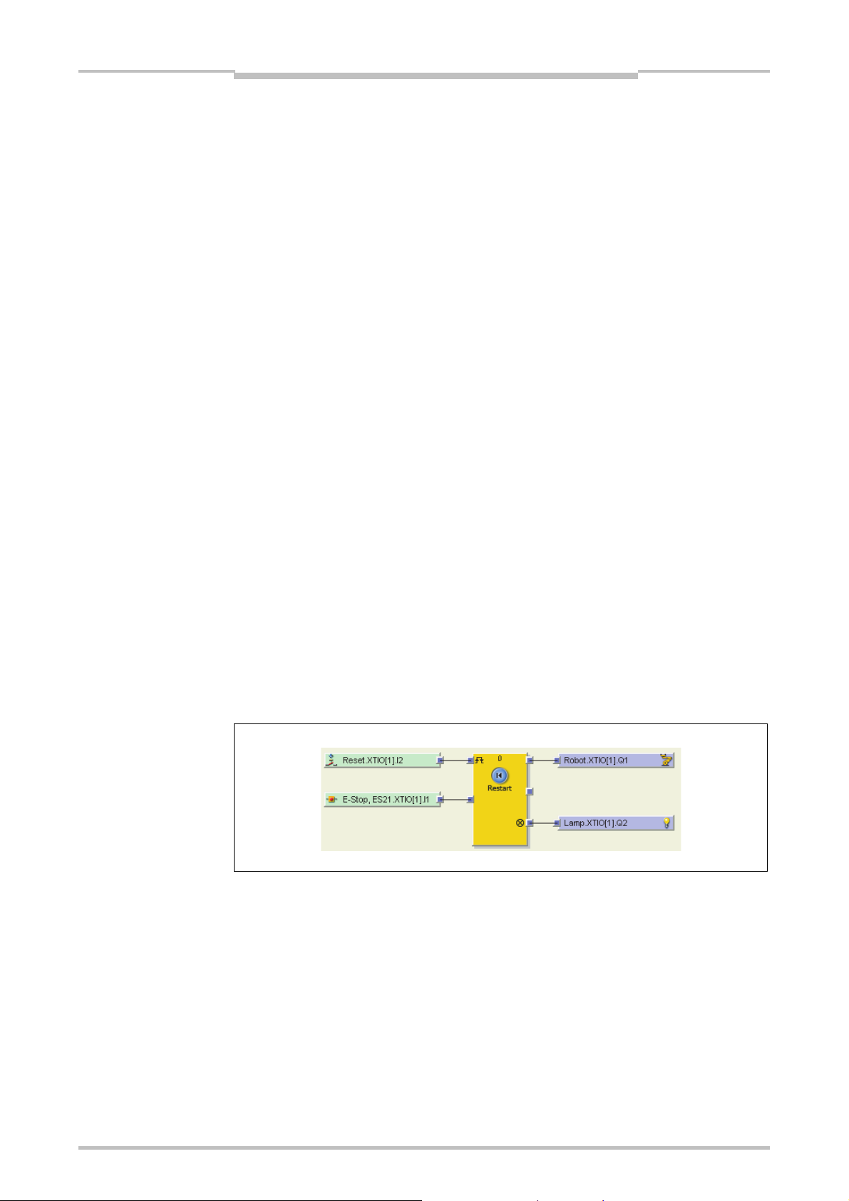
Figure 55:
Logic configuration example
(Station A)
Flexi Link
Chapter 7
7.3.3 Flexi Link configuration
This section shows in detail how data can be shared between the single stations in a
Flexi Link system.
Example: Simple Flexi Link project with two stations. An emergency stop button and a
restart button on Station A will control two robots connected to Station A and Station B.
Setting up the hardware
Create a new Flexi Link project (see Section 7.3.2).
In the Flexi Link System overview, set the connection method to EFI1+2 (setting
it to EFI1 will make no difference for this example project). Then click on the Add
a new station button for Station A. The Hardware configuration view for Station
A opens.
Add a CPU1 or CPU3 and then an WS0-XTIO module for Station A.
Connect a single channel emergency stop button to input I1 and a single channel
reset button to input I2 of the Station A WS0-XTIO module.
Connect a single channel robot to output Q1 and a lamp to output Q2 of the Station
A WS0-XTIO module.
Now click on the button for Station B in the toolbar. The Hardware configuration
view for Station B opens.
Add a CPU1 or CPU3 and then an WS0-XTIO module for Station B.
Connect a single channel robot to output Q1 and a lamp to output Q2 of the Station
B WS0-XTIO module.
Configuring the logic for Station A
Click on the button for Station A in the toolbar. Then switch to the Logic editor view
for Station A.
Using the connected input and output elements on the WS0-XTIO module and a
Restart function block, create the following logic configuration:
86
Page 90

Chapter 7
Figure 56:
CPU outputs in the output
selection window
Note
Flexi Link
Configuring the Flexi Link routing for Station A
In the Logic editor for Station A, add an additional Routing N:N function block,
configure it for two inputs and outputs and connect its inputs to the WS0-XTIO
inputs for the reset button and the emergency stop button.
Drag two outputs of the Station A CPU module on the logic editor worksheet. You
will find the outputs in the output selection window under CPU1 or CPU3.
A square with the letter A-D within it denotes a bit within the Flexi Link process
image.
Figure 57:
Flexi Link routing logic
example
Recommendation
Each output can be used only once. Used outputs are displayed green.
Connect the outputs of the Routing N:N function block to the two CPU1[A] outputs
(e.g. Info 0.3.CPU1[A].EFI1 and Info 0.4.CPU1[A].EFI1) as shown in Figure 57.
Note which input is being routed to which output.
In more complex projects, configure the routing connections on a separate page in the
logic editor. Otherwise the logic design could get confusing.
87
Page 91

Figure 58:
Flexi Link routing table and
tag names
Flexi Link
Chapter 7
Assigning tag names for the Flexi Link routing
Still in the Station A view, switch to the Flexi Link routing table using the Flexi Link
station A button in the toolbar (if your project contains also one or two network
modules, you will find this entry in the submenu under Network modules).
Click on Byte 0 in the EFI1 area to display the tag names for Byte 0 and its bits in
the lower half of the window.
Figure 59:
Assigned Flexi Link tag
names in the routing
configuration and in the logic
editor
Note
Now replace the default tag names (e.g. Safe 0.3 and Safe 0.4) with more
expressive tag names (e.g. Global Reset and Global E-stop). The assigned tag
names will be displayed in the logic editor from now on.
It does not make a difference for the routing whether you use the default tag names or
change them, but assigning clear tag names will help you to keep track of things in
your projects.
88
Page 92

Chapter 7
Figure 60:
Routed inputs from Station
A in the Station B logic
editor
Figure 61:
Logic configuration example
(Station B)
Flexi Link
Configuring the logic for Station B
Click on the button for Station B in the toolbar. Then switch to the Logic editor view
for Station B.
In the inputs selection window, find the two inputs from the Station A CPU module
that are routed via Flexi Link. You can recognize them by their tag names:
Using these inputs, the output elements on the Station B WS0-XTIO module and a
Restart function block, create the following logic configuration:
With this step the example project is finished. The input from the emergency stop
button and from the reset button connected to Station A is routed to Station B via Flexi
Link so that the robots connected to both stations can be controlled simultaneously.
89
Page 93

Figure 62:
Flexi Link system overview,
system not connected
Flexi Link
Chapter 7
7.3.4 Transferring and verifying the Flexi Link configuration
To start your Flexi Link system, connect the PC with the system, transfer and verify
the configurations and switch the stations into the Run state. This requires that you
have finished the configuration as described in the previous section and that you have
set up and connected the required MELSEC-WS modules and other hardware.
Establish a connection to your Flexi Link system
Connect a PC or notebook to the RS-232 interface of any CPU module in the
system.
Power on the Flexi Link system.
Open the Setting and Monitoring Tool installed on the PC and load the project file
with your configuration.
If necessary, adjust the communication settings (see Section 6.2).
Switch to the Flexi Link system overview. The configured stations in your project
will be displayed with a light yellow background.
Figure 63:
Connect dialog
Click on Connect. You will be prompted to select the stations you want to connect
to. Activate all stations, then click OK.
If the CPU modules of the connected stations have not been configured for Flexi
Link before, the Setting and Monitoring Tool will now open the Flexi Link Network
settings view and list the found stations. In this case you will have to assign a
unique Flexi Link address from A to D to the individual stations as described in
Section 7.3.1.
90
Page 94

Chapter 7
Figure 64:
Flexi Link system overview,
system connected, differing
configurations
Flexi Link
The Setting and Monitoring Tool will connect to the Flexi Link system, compare the
existing hardware and software configuration with the configuration in the Designer
and display the results. If the configuration in the Setting and Monitoring Tool is not
identical to the configuration in the connected stations, these will be displayed with a
blue background.
Figure 65:
Flexi Link system overview,
system connected,
configuration identical but
not verified
Transfer the configuration
Now transfer the configuration to the stations by clicking on Transfer. Again you will
be prompted to select which station(s) you want to transfer the configuration to.
Select all stations and click on OK. The Setting and Monitoring Tool will now
transfer the configuration to each station. You will need the password for
Administrator; the default password is “MELSECWS”.
Once a valid configuration has been transferred to a station successfully, the
Setting and Monitoring Tool will ask you whether you want to set this station into the
Run state. Click either Yes or No. The station will be displayed in the Flexi Link
system overview with a grey background.
91
Note
You can run or stop each station also in the Hardware configuration view for the
respective station.
Page 95

Note
Flexi Link
Chapter 7
Verify the configuration
Switch to the Hardware configuration view for any station in your project. If the
device configuration is valid and equal with the configuration in the Setting and
Monitoring Tool, but not yet verified, the CV LED on the CPU module will flash as
well as the Upload and verify configuration button on the left side of the
configuration area.
Click the Upload and verify configuration button. The Setting and Monitoring
Tool will upload the configuration from the module and compare it to the
configuration in the Setting and Monitoring Tool. If both configurations match, the
result will be displayed as a report and you will be asked whether you want to set
the device to Verified. Read the report carefully.
You can print the report or save it in PDF format.
If you have checked the report and want to set the device to Verified, click Yes.
The device will be set to Verified. If it is currently not in the Run state you will now
be asked whether you want to start it.
Repeat this for all stations in your Flexi Link system.
For more detailed information on transferring and verifying a configuration please see
Chapter 10.
92
Page 96

Chapter 7
Figure 66:
Flexi Link system and
station buttons
Figure 67:
Flexi Link system menu bar
Flexi Link
7.4 Flexi Link functions
This section gives a comprehensive overview over the Flexi Link functions in the
Setting and Monitoring Tool. These functions are divided into Flexi Link system
functions and functions that are related to the single stations in a Flexi Link system.
You can switch between the view for the Flexi Link system and the individual station
views using the additional buttons that appear in the toolbar of the Setting and
Monitoring Tool if a Flexi Link project is open.
Flexi Link system functions
In the Flexi Link system view, you can switch between the different Flexi Link system
functions using the buttons that are displayed under the menu bar:
Figure 68:
Flexi Link station menu bar
The Flexi Link System overview provides information on the configured/connected
stations and their status. See Section 7.4.1.
The Flexi Link process image allows you to monitor the information that is
exchanged between the connected Flexi Link stations. See Section 7.4.2.
In the Flexi Link Network settings view you can scan the Flexi Link network for
connected stations, view and assign the Flexi Link address to the connected
stations and distribute the stations to their individual positions (A to D) in the Flexi
Link network. See Section 7.4.3.
The EFI1/2 and EFI1 radio buttons are used to choose the connection method, i.e.
whether one or two EFI strings are used.
On the right side the Flexi Link IDs for the current configuration in the Setting and
Monitoring Tool are displayed.
Flexi Link station functions
The Flexi Link functions for an individual station can be reached if the view for this
station is active:
93
Most of these functions as the Hardware configuration, Report or Diagnostics
are working in the same way as in a standalone project. In this section only the
additional functions that are relevant for Flexi Link will be described.
Page 97

Figure 69:
Flexi Link station menu bar
with network module
Flexi Link
Chapter 7
The Logic editor is used to configure which information each station will send to
the other stations via the Flexi Link network. This is also where the information
provided by the other Flexi Link stations in the network is available and can be used
as input for logic applications. See Section 7.4.4.
The Flexi Link station X view is where you can assign tag names to the source
information that the station sends to the Flexi Link network and change the process
image default values (High or Low). These values will be used in case the Teach
function is used to simulate the presence of this station. See Section 7.4.5 and
Section 7.4.6.
If a network module is connected to the station, the Flexi Link Station X button is
integrated in the Network modules menu:
Figure 70:
Flexi Link system overview
7.4.1 Flexi Link system: System overview
The Flexi Link System overview provides information on the configured/connected
stations and their status. To open the system overview, first click on the Flexi Link
system button in the toolbar and then on the System overview button.
In this view each station is displayed with its current hardware configuration,
information on the connected CPU, online status, configuration status and Flexi Link
IDs. The background color of each station also indicates its online status and
configuration status as shown in Figure 70.
In the example above, Station A is offline (light yellow background), while station B is
online with a valid configuration (grey background), station C is online with an invalid
configuration (blue background) and no station D has been configured (light yellow
background).
94
Page 98

Chapter 7
Table 15:
Flexi Link system overview
tools
Flexi Link
To the left of each station you will find the following tool icons:
Icon Function Description
Add Adds a new station in the current slot (A to D) and switches to
Edit Switches to the view for this station. There you can edit its
Recognize Connects to this station, uploads its hardware configuration,
Delete Deletes this station from the current configuration.
Connect Connects to this station so that you can upload, transfer or verify
the view for the new station. This function is only available if no
station has been configured for this slot yet.
properties including the station name, configure the connected
hardware, program the logic, verify and lock the configuration
etc.
then prompts you whether the software configuration shall be
uploaded from this station.
Note: You will not be asked to confirm this command and there
is no Undo function. Unsaved changes will be lost.
the configuration, run or stop the application etc.
Note
Disconnect Disconnects from this station so that you can e.g. edit the
configuration.
If a function is not available, the corresponding icon is displayed grey.
Instead of clicking the Add or Edit button, you can also switch to the view for an
individual station by clicking the corresponding button for Station A to D or by
double clicking on that station’s graphical representation.
The Connect or Disconnect buttons next to each station perform their function
only for this station while the Connect or Disconnect button in the menu bar for the
Flexi Link system overview will connect to or disconnect from the entire Flexi Link
system (when you click Connect there you will be asked which stations you want to
connect to).
It is not possible to set all stations into the Run state or to stop them all
simultaneously in the Flexi Link system overview. You need to switch to the station
view for each station and to log in individually to each station as Administrator with
the password for this station in order to run it or to verify the configuration.
95
Page 99

Figure 71:
Flexi Link process image
Flexi Link
Chapter 7
7.4.2 Flexi Link system: Process image
The Flexi Link process image allows you to monitor the information that is
exchanged between the Flexi Link stations. In the left area of the screen the hardware
configuration for each station is displayed, on the right side the bits for EFI1 and EFI2
(if used) are displayed with their tag names. Bits that are currently High in the process
image are highlighted green.
Note
If a station is not in the Run state, its process image will be set to Low and its I/O
error status bits will be set to High (see Section 5.6.5).
Double clicking on the hardware symbol for a station will open the routing view for
this station where you can edit the tag names for the bits and bytes sent from this
station (see Section 7.4.4).
96
Page 100

Chapter 7
Figure 72:
Flexi Link Network settings
view
Flexi Link
7.4.3 Flexi Link system: Network settings
The Network settings view is where you can assign the Flexi Link address (A, B, C or
D) to the individual stations in the Flexi Link network. This is a prerequisite for the
configuration because it enables the Flexi Link Designer to address each station and
to identify the bits in the Flexi Link process image, e.g. Station A, EFI1, Byte 0, Bit 0.
The Network settings view is opened automatically if you connect to a Flexi Link
system and the Setting and Monitoring Tool detects an erroneous address assignment,
e.g. if two or more connected stations have the same Flexi Link address. This will be
the case if you have created a Flexi Link system with new CPU modules or if you have
replaced one or more CPU modules in an existing system.
Note
If at least one station of a Flexi Link system is online, all connected stations are shown
with their current address assignment (address A to D). Additionally the memory plug
serial number and the current Flexi Link IDs for EFI1 and EFI2 of each station are
displayed here. You can update this information using the Scan button at the top left
of the window. Error messages and warnings regarding the current system status are
displayed as a pop-up message for each station.
You have two possibilities to identify a station:
– Click on the Start identify button of one of the displayed stations. The
corresponding station’s MS and EFI1 LEDs will start flashing alternating with the
EFI2 LED (2 Hz). You will need the password for Administrator. The default
password is “MELSECWS”. To stop the LED blinking, click the button again (it
is now labeled Stop identify).
– Check the serial number on the memory plug and compare it with the serial
number shown in the Setting and Monitoring Tool. The serial number displayed
in the Network settings view is the serial number of the memory plug, not the
serial number of the CPU module.
97
 Loading...