

Page 1

Model
PU(H)Y-P250YGM-A
PUHY-P500YGM-A
PFD-P250VM-E
PFD-P500VM-E
DATA BOOK
AIR CONDITIONERS
Page 2

CONTENTS
1. Specifications
1-1 Main Features
1-2
List of Possible Combinations of Indoor and Outdoor Units
1-3 Unit Specifications
2. Capacity Curves
2-1 Cooling Capacity
2-2 Cooling Input
2-3 SHF Curves
2-4 Correction by refrigerant piping length
2-5 Operation limit
3. Sound Levels
3-1 Noise Level
3-2 NC Curves
3-3 Fan Characteristics Curves
4. External Dimensions
5. Electrical Wiring Diagrams
6. Refrigerant Circuit Diagram And Thermal Sensor
7. System Design
7-1 Refrigerant Piping System
7-2 Control Wiring
7-3 Types of switch settings and setting methods
7-4 Sample System Connection
7-5 External input/output specifications
8. Air Conditioning the Computer Room
8-1 Main Features of the Floor-Duct Air Conditioners
8-2 Features of air-conditioner for computer room
8-3
Step-by-Step Plan for the Implementation of the Air-Conditioning
8-4
Conditions for the Installation of Computer-Room Air Conditioners
8-5 Setting the Air conditioners
8-6 Automatic Control of the Computer Room
9. Maintenance/Inspection
9-1 Maintenance/Inspection Schedule
1
1
2
3
4
4
4
5
6
6
7
7
8
8
10
14
18
20
20
21
22
24
29
33
33
33
34
35
36
38
39
39
Close control
PU(H)Y-P-YGM-A
PFD-P-VM-E
······························································
······························································
·····
·························································
·························································
·························································
·························································
·························································
····························
·························································
···································································
···································································
···································································
···········································
···········································
·································································
······················································
···
··············································
·································································
················
············································
·······························
················
···
···
·························
··········
·············································
······················
···············································
·······························
Page 3

Page 4
1. Specifications
1-1.Main Features
1
(1) List of Models
<10HP System>
<20HP System>
Single refrigerant circuit
PU(H)Y-P250YGM-A
PUHY-P500YGM-A
10HP(Down flow): PFD-P250VM-E
20HP(Down flow): PFD-P500VM-E
✻ PFD-type indoor units cannot be connected to outdoor units other than the ones specified above.
✻ It is necessary to rewrite the S/W on the control circuit board of the outdoor unit connected to
the PFD-type indoor units.
✻ PFD-type indoor units and other types of indoor units cannot coexist in the same refrigerant system.
✻ It is necessary to change pulley and V-belt when using it by the power supply frequency 60Hz.
✻ For restrictions when the PFD-type indoor units are connected (related to the system), see P21.
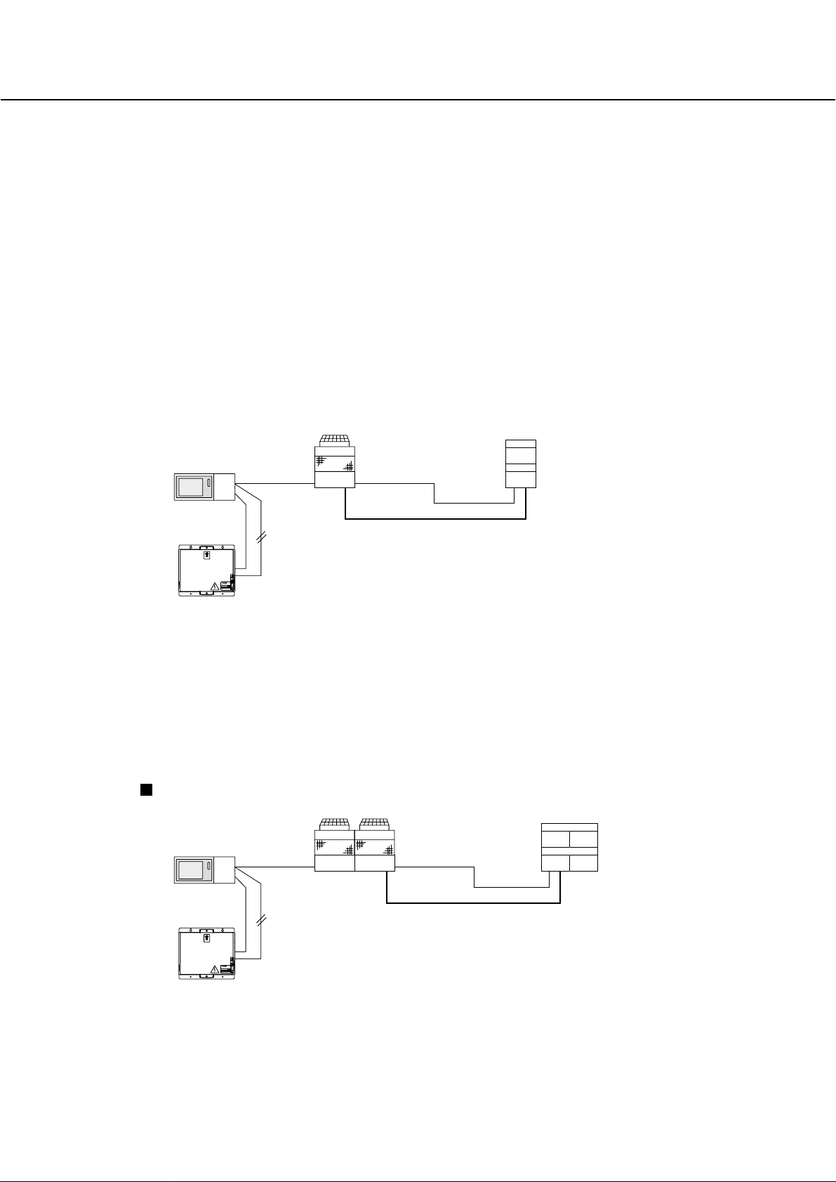
When using a PFD-P500VM-E as an indoor unit, connect an outdoor unit PUHY-P500YGM-A to
each indoor unit and operate with a built-in remote control for the indoor unit.
✻1: Bold line indicates refrigerant piping (gas/liquid). This system consists of single refrigerant circuit.
✻2: Indicates TB3-type transmission line that connects the indoor and outdoor units.
This system consists of single refrigerant circuit.
✻3: Indicates TB7-Type transmission line that allows the unit to communicate with the controller.
When using a PFD-P250VM-E as an indoor unit, connect an outdoor unit PU(H)Y-P250YGM-A to
each indoor unit and operate with a built-in remote control for the indoor unit.
✻1: Bold line indicates refrigerant piping (gas/liquid). This system consists of single refrigerant circuit.
✻2: Indicates TB3-type transmission line that connects the indoor and outdoor units.
This system consists of single refrigerant circuit.
✻3: Indicates TB7-Type transmission line that allows the unit to communicate with the controller.
} Outdoor Unit
} Indoor Unit
Outdoor Unit
G-50A
PU(H)Y-P250YGM-A
Indoor Unit
PFD-P250VM-E
TB7
TB3 ✻2✻3
✻1
12V DC
M-NET
PAC-SC50KUA
UP
POWER RATING
MODEL
WEIGHT
SERIAL No.
2.11kg
POWER SUPPLY UNIT
MITSUBISHI ELECTRIC CORPORATION
PAC-SC50KUA
Outdoor Unit Indoor Unit
TB7
TB3 ✻2
✻1
PUHY-P500YGM-A PFD-P500VM-E
G-50A
12V DC
M-NET
PAC-SC50KUA
UP
POWER RATING
MODEL
WEIGHT
SERIAL No.
2.11kg
POWER SUPPLY UNIT
MITSUBISHI ELECTRIC CORPORATION
PAC-SC50KUA
Page 5
2
1-2. List of Possible Combinations of Indoor and Outdoor Units
✻1: Refer to the following pages for detailed specifications of each unit.
✻2: They were measured at operation under the following conditions:
<Cooling> Indoor:27˚CDB/19˚CWB Outdoor:35˚CDB
<Heating> Indoor:20˚CDB Outdoor: 7˚CDB/6˚CWB
Pipe length:7.5m, Height difference:0m
Model Name Indoor unit
Outdoor unit
Cooling Heating
System capacity kW 28.0 31.5
System Power input kW 9.3 9.1
System current A 16.7/15.9/15.4 16.4/15.5/15.1
10HP system
PFD-P250VM-E
PU(H)Y-P250YGM-A
Cooling Heating
56.0 63.0
18.6 18.2
32.3/30.8/29.7 31.7/30.0/29.1
20HP system
PFD-P500VM-E
PU(H)Y-P250YGM-A x 2
or PUHY-P500YGM-A
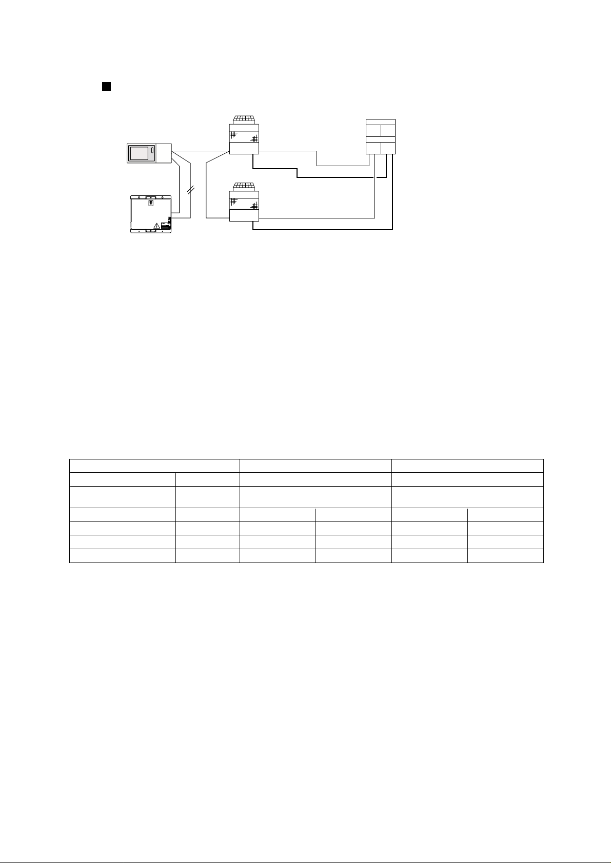
When using a PFD-P500VM-E as an indoor unit, connect 2 PU(H)Y-P250YGM-A outdoor units to
each indoor unit and operate with a built-in remote control for the indoor unit.
At factory shipment, this model of indoor unit is designed and set to accommodate a single refrigerant circuit.
Connection of two refrigerant circuits to the indoor unit requires setting change and pipe work.
✻1: Bold line indicates refrigerant piping (gas/liquid). This system consists of two refrigerant circuits.
✻2: Indicates TB3-type transmission line that connects the indoor and outdoor units.
This system consists of two refrigerant circuits.
✻3: Indicates TB7-type transmission line that allows the unit to communicate with the controller.
Outdoor Unit
PU(H)Y-P250YGM-A
Indoor Unit
PFD-P500VM-E
TB7
TB3 ✻2
✻1
TB3
PU(H)Y-P250YGM-A
TB7
✻3
G-50A
12V DC
M-NET
PAC-SC50KUA
UP
POWER RATING
MODEL
WEIGHT
SERIAL No.
2.11kg
POWER SUPPLY UNIT
MITSUBISHI ELECTRIC CORPORATION
PAC-SC50KUA
Two refrigerant circuits
Page 6
(2) Indoor Unit
3
1-3. Unit Specifications
28.0 31.5
3N ~ 380/400/415V 50/60Hz
Capacity
Model name
kW
Power source
✻
1
✻
2
kW
A
m
3
/min
kW
kW
kW
mm
dB(A)
kg
Power input
Current
Fan
Airflow rate
Type ✕ Quantity
Motor output
Type
Motor output
Crankcase heater
Compressor
Refrigerant / Lubricant
External finish
High pressure protection
Inverter
Compressor
Fan
External dimension HxWxD
Protection
devices
Refrigerant
piping diameter
High press. pipe
Low press. pipe
Noise level
Net weight
1,840 x 990 x 840
Propeller fan x 1
200
0.38
Hermetic
6.7
0.045 x 1
R410A/MEL32
Heat exchanger Salt resistant fin
Over current protection / Thermal protection
ø9.52 Flare (ø12.7 for over 90m)
ø22.2 Brazed
Pre-coated galvanized sheets (+ powder coating for -BS type) <MUNSEL 5Y 8/1 or similar>
4.15MPa
233
6.66.8
11.1/10.5/10.211.4/10.9/10.5
PU(H)Y-P250YGM-A (-BS)
connected with PFD series
PUHY-P500YGM-A (-BS)
connected with PFD series
Over current protection / Over heat protection
Thermal switch
57/57
56.0 63.0
Cooling Heating Cooling Heating
1,840 x 1,990 x 840
Propeller fan x 2
400
0.38 x 2
8.2+5.3
0.045 x 2
ø15.88 Flare
ø28.58 Brazed
455
13.6 13.2
22.2/21.0/20.422.8/21.8/21.0
60/61
Note: *1. Cooling/Heating capacity indicates the maximum value at operation under the following condition.
*2. It is measured in anechoic room.
** Installation/foundation work, electrical connection work, duct work, insulation work, power source switch,
and other items shall be referred to the Installation Manual.
Indoor : 27
˚CDB / 19˚CWB
Indoor : 20
˚CDB
Pipe length : 7.5m
Outdoor :
Outdoor :
Height difference : 0m
35
˚CDB
7
˚CDB
/ 6
˚CWB
<Cooling>
<Heating>
3N~380/400/415V(50Hz), 400/415V(60Hz)
PFD-P500VM-E
5.0
Power source
kW
-
Power input
System capacity
A
m
3
/min
Pa
kg
dB(A)
m
mm
Current
Heat exchanger
Fan
Refrigerant
External finish
Type x Quantity
Airflow rate
External static pressure
kW
Motor Output
Air filter
Refrigerant
piping diameter
✻2
Refrigerant piping allowable length
Gas pipe
Liquid pipe
Cross fin (Aluminum plate fin and copper tube)
Sirocco fan x 2Sirocco fan x 1
ø
9.52 Brazed (ø 12.7 for over 90m)
ø 22.2 Brazed
Single refrigerant
circuit
Two refrigerant
circuit
320
1,950 x 1,380 x 780
9.5/9.0/8.7
PFD-P250VM-E
2.5
kW 28.0 31.5 56.0 63.0
5.3/5.0/4.9
160
120120
4.42.2
380
59
150
Gas pipe
Liquid pipe
ø
15.88 Brazed
ø 28.58 Brazed
Gas pipe
Liquid pipe
ø
9.52 Brazed (ø 12.7 for over 90m)
ø 22.2 Brazed
520
63
150
R410A
Galvanized steel plate (with polyester coating)
<MUNSEL 2.9GY 8.6/0.3(White) 7.2GB 3.2/5.3(Blue) or similar>
PP Honeycomb fabric (washable)
Thermal switch
1,950 x 1,980 x 780
Protection devices (Fan)
External dimensions
HxWxD
Model name
Noise level
Net weight
Cooling Heating ✻1 ✻1Cooling Heating
Note: *1. Heating can be used only by the indoor warming-up.
*2. At factory shipment, this model of indoor unit is designed and set to accommodate a single refrigerant circuit.
Connection of two refrigerant circuits to the indoor unit requires setting change and pipe work.
** Installation/foundation work, electric connection work, duct work, insulation work, power source switch and other items are
not specified in the specifications.
(1) Outdoor Unit
Page 7
4
2. Capacity Curves
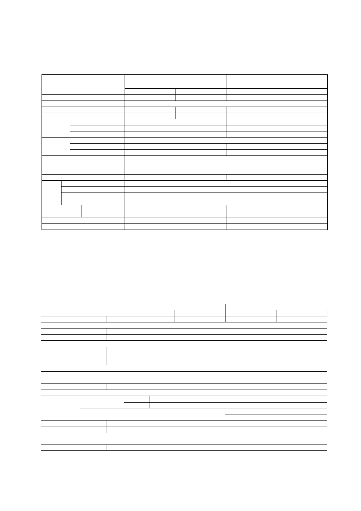
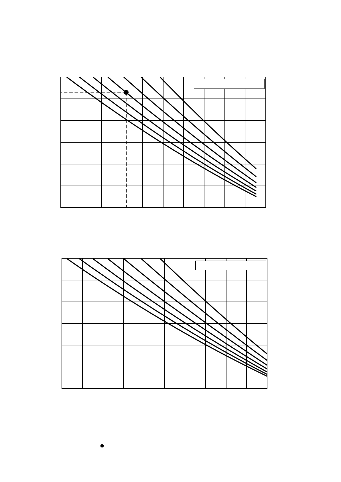
2-1. Cooling Capacity
0.7
0.8
0.9
1.0
1.1
1.2
1.3
1.4
-15 -10 -5 0 5 10 15 20 25 30 35 40 45
Indoor unit inlet temperature (˚CWB)
Indoor unit inlet temperature (˚CWB)
19
15
12
24
0.7
0.8
0.9
1.0
1.1
1.2
1.3
19
24
15
12
-15 -10 -5 0 5 10 15 20 25 30 35 40 45
Capacity correction coefficientInput Correction Coefficient
Outdoor unit inlet temperature (˚CDB)
Outdoor unit inlet temperature (˚CDB)
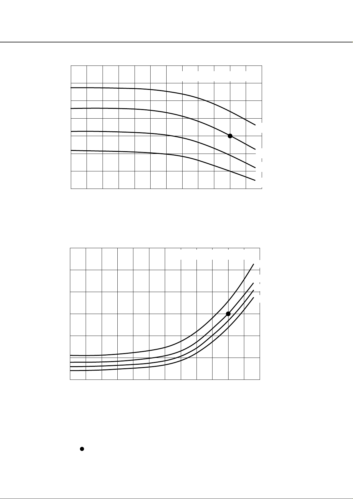
2-2. Cooling Input
✻ The correction curves indicate the values measured at the point where the compressor was
operated at its maximum capacity.
✻ indicates the standard value.
Page 8
5
2-3. SHF Curves
Operation Temparature Range: Indoor : 12˚CWB~24˚CWB
Outdoor: -15˚CDB~43˚CDB
(RH : 30~80%)
Standard Point " " : Indoor : 27˚CDB/19˚CWB
Outdoor: 35˚CDB/-
0.4
0.5
0.6
0.7
0.8
0.9
1
30 40 50 60 70 80
RH (%)
SHF
130% 120%110%100% 90% 80% 70%
Standard Capacity Ratio
Standard Capacity Ratio
0.93
0.4
0.5
0.6
0.7
0.8
0.9
1
30 40 50 60 70 80
RH (%)
SHF
130% 120%110%100% 90% 80% 70%
35 45 55 65 75
Indoor Temperature 27˚CDB
35 45 55 65 75
Indoor Temperature 24˚CDB
Page 9

6
2-4. Correction by refrigerant piping length
To obtain a decrease in cooling/heating capacity due to refrigerant piping extension, multiply by the capacity
correction factor based on the refrigerant piping equivalent length in the table below.
• Cooling
Equivalent length = (Actual piping length to the farthest indoor unit) + (0.50 ✕ number of bent on the piping)m
• How to obtain piping equivalent length
Piping equivalent length (m)
Capacity correction coefficient
0.7
0.8
0.9
1
0 20 40 60 80 100 120 140 160 180
2-5. Operation limit
Indoor temperature (˚CWB)
-15 0-5-10 5 1015202530354045
10
12
15
20
25
30
* The height between the Outdoor PU(H)Y-P-YGM-A and Indoor could make the running
temperature range narrow. For details refer to P20, 7-1 Refrigerant Piping System.
Outdoor temperature (˚CDB)
• Heating
Outdoor temperature (˚CWB)
Indoor temperature (˚CDB)
30
25
20
15
10
5
-20 -15 -10 -5 0 5 10 15 20 25 30 35 40 45 50
Page 10
3. Sound Levels
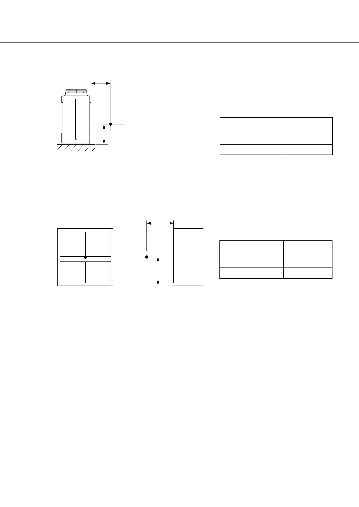
3-1. Noise Level
7
1m
1m
Measured
point
Series
Noise Level
(dB [Type A])
PFD-P250VM-E 59
PFD-P500VM-E 63
(1) Outdoor Unit
(2) Indoor Unit
Measured
point
1m
1m
Series
Noise Level
(dB [Type A])
PU(H)Y-P250YGM-A 57
PUHY-P500YGM-A 60/61
(50Hz/60Hz)
Page 11
8
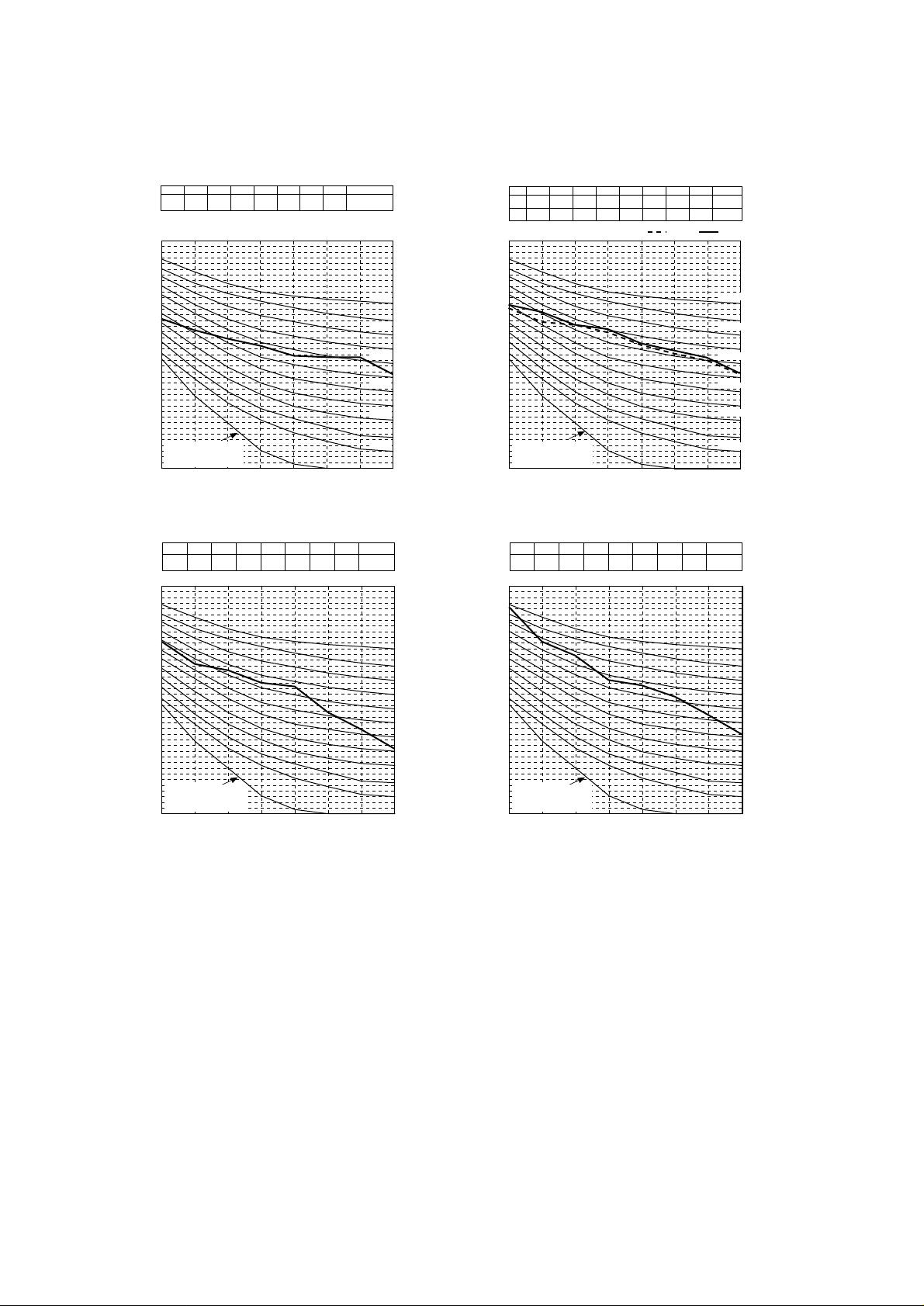
3-2. NC Curves
PU(H)Y-P250YGM-A
(External static
pressure 0Pa)
PUHY-P500YGM-A
(External static
pressure 0Pa)
PFD-P250VM-E
(External static
pressure 120Pa)
PFD-P500VM-E
(External static
pressure 120Pa)
63Hz 125Hz 250Hz 500Hz 2000Hz1000Hz 4000Hz 8000Hz
dB(A)
82.8 70.5 65.6 57,0 55.1 51.1 44.7 37.9 63
63Hz 125Hz 250Hz 500Hz 2000Hz1000Hz 4000Hz 8000Hz
dB(A)
70.6 62.7 60.5 56.1 54.8 45.7 39.7 32.9 59
10
20
30
40
50
60
70
80
90
63Hz 125Hz 250Hz 500Hz 1000Hz 2000Hz 4000Hz 8000Hz
10
20
30
40
50
60
70
80
90
63Hz 125Hz 250Hz 500Hz 1000Hz 2000Hz 4000Hz 8000Hz
NC-70
NC-60
NC-50
NC-40
NC-30
NC-20
NC-70
NC-60
NC-50
NC-40
NC-30
NC-20
OCTAVE BAND PRESSURE LEVEL (dB) 0dB = 20µPaOCTAVE BAND PRESSURE LEVEL (dB) 0dB = 20µPa
OCTAVE BAND CENTER FREQUENCIES (Hz)
OCTAVE BAND CENTER FREQUENCIES (Hz)
63 125 250 500 1000 2000 4000 8000
10
20
30
40
50
60
70
80
90
Approximate minimum
audible limit on
continuous noise
NC-70
NC-60
NC-50
NC-40
NC-30
NC-20
63Hz 125Hz 250Hz 500Hz 2000Hz1000Hz 4000Hz 8000Hz
dB(A)
62.5 58.5 55.5 53 49.5 49 49 43 57
50Hz 60Hz
OCTAVE BAND PRESSURE LEVEL (dB) 0dB = 20µPaOCTAVE BAND PRESSURE LEVEL (dB) 0dB = 20µPa
OCTAVE BAND CENTER FREQUENCIES (Hz)
OCTAVE BAND CENTER FREQUENCIES (Hz)
63 125 250 500 1000 2000 4000 8000
10
20
30
40
50
60
70
80
90
Approximate minimum
audible limit on
continuous noise
Approximate minimum
audible limit on
continuous noise
Approximate minimum
audible limit on
continuous noise
NC-70
NC-60
NC-50
NC-40
NC-30
NC-20
63Hz 125Hz 250Hz 500Hz 2000Hz1000Hz 4000Hz 8000Hz
dB(A)
67
50Hz
60Hz
61.5 60.5 58 53.5 50.5 48 43 60
68 65 60.5 59 54 51.5 49 43.5 61
Page 12

9
3-3. Fan Characteristics Curves
PFD-P250VM-E
PFD-P500VM-E
: 50/60Hz, standard
: 50/60Hz, standard
0
100
200
300
400
500
600
700
800
900
1000
130 140 150 160 170 180 190
)aP(erusserpcitatsla
t
oT
Fan rotation speed
Internal
resistance
1200rpm
1100rpm
1000rpm
900rpm
800rpm
Output 3.7kW
136 184
Air volu me (m3/min)
Air volu me (m3/min)
✻ Pulley and V-belt is procured on site.
✻ Pulley and V-belt is procured on site.
290 310 330 350
318 345
250
0
100
200
300
400
500
600
700
800
270
)aP(erusserpcitatslatoT
272
800rpm
800rpm
Internal resistance
Fan rot ation speed
Output
5.5kW
StandardStandard
1000rpm
1100rpm
1000rpm
900rpm
900rpm
1
2
3
4
5
6
7
8
9
3
4
5
6
7
8
9
2
6
No.
3
4
5
6
7
8
9
No.
1
3
4
5
7
8
9
1170
1140
1080
1040
973
930
845
797
748
Rotational
speed
(rpm)
1135
1070
1015
978
905
850
803
Rotational
speed
(rpm)
ø315-B-2-42
ø315-B-2-42
ø250-B-2-42
ø250-B-2-42
ø280-B-2-42
50Hz
Motor pulle y Fan pulley
ø170-B-2-38
ø180-B-2-38
ø170-B-2-38
ø180-B-2-38
ø180-B-2-38
ø160-B-2-38
ø170-B-2-38
ø236-B-2-42
ø250-B-2-42
50Hz
Motor pulle y Fan pulley
ø160-B-2-28
ø160-B-2-28
ø170-B-2-28
ø165-B-2-28
ø165-B-2-28
ø165-B-2-28
ø165-B-2-28
ø170-B-2-28
ø160-B-2-28
ø315-B-2-42
ø280-B-2-42
ø200-B-2-42
ø212-B-2-42
ø224-B-2-42
ø236-B-2-42
ø280-B-2-42
ø315-B-2-42
ø250-B-2-42
B48
B49
B50
B51
B52
B54
B53
B56
B56
V-belte
B51
B51
B51
B50
B53
B56
B55
V-belte
60Hz
Motor pulle y Fan pulle y
ø280-B-2-42
ø165-B-2-28
ø165-B-2-28
ø165-B-2-28
ø180-B-2-28
ø170-B-2-28
ø355-B-2-42
ø250-B-2-42
ø280-B-2-42
ø280-B-2-42
-
ø160-B-2-28
ø160-B-2-28
ø170-B-2-28
ø300-B-2-42
ø315-B-2-42
ø355-B-2-42
-
ø300-B-2-42ø180-B-2-38
ø355-B-2-42
ø355-B-2-42ø160-B-2-38
60Hz
Fan pulleyMotor pulle y
ø160-B-2-38 ø250-B-2-42
ø280-B-2-42
ø300-B-2-42
ø170-B-2-38
ø160-B-2-38
ø160-B-2-38
ø160-B-2-38 ø315-B-2-42
B52
B56
B54
B54
B55
B56
B59
B59
-
V-belte
B50
B55
B52
B54
B55
B58
B58
V-belte
Page 13
10
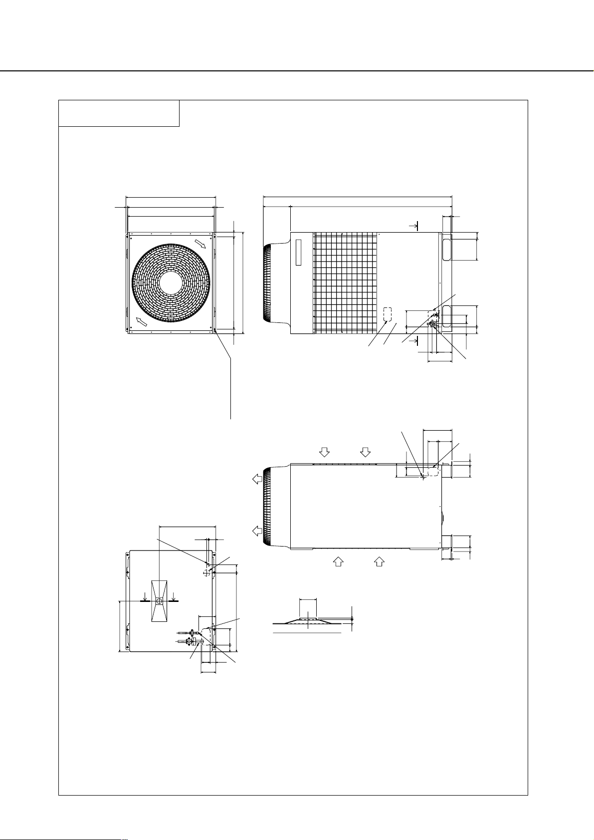
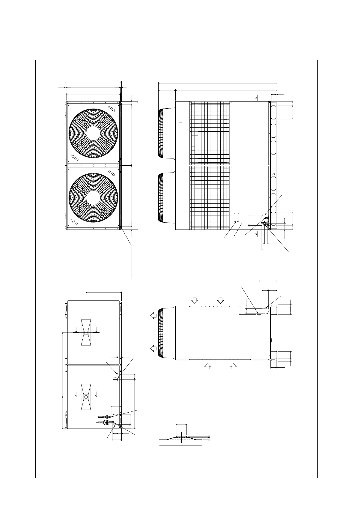
4. External Dimensions
PU(H)Y-P250YGM-A
Unit : mm
Note1.Use the opening at the bottom of the unit
when running the power supply line from
the front or from the side of the unit.
Note2.Please refer to the next page for information
regarding necessary spacing around the
unit and foundation work.
166
83100
44150
Y
Y
20
70
80
100
90
10
4080
135
280
134
553
494
8057
16065
768
37 117 117 37
1575
1840
11
235
16067
990
16
840
67 207
207
67
78
X
X
877
845(mounting pitch)16
45900(mounting pitch)45
265
ø53
12 5
Conn. pipe(Liquid)
ø9.52 <Flare>
Conn. pipe(Gas)
ø22.2 <Brazed>
(Mounting hole)
Air outlet
Air
inlet
Air
inlet
ø62 Knockout hole
<Hole for power supply>
Changeable to ø27,ø33 by using
attached conduit mounting plate <Accessory>
ø27 Knockout hole
<Bottom hole for
control wiring>
Knockout hole
<Bottom piping hole>
Left side view
ø27 Knockout hole
<Left side hole for
control wiring>
Knockout hole
<Left piping hole>
<Accessories>
• Refrigerant (Gas) conn. pipe......1 pc.
(Already installed on the unit)
• Packing for conn. pipe................1 pc.
(Attached near the ball valve)
• Conduit mounting plate
ø33, ø27..............................1 pc.Each
• Tapping screw M4......................2 pcs.
Cross section Y – Y
Cross section X – X
2X2-14X20 0val hole
Top view
Front view
Knockout hole
Service panel
Refrig. service
valve (Liquid)
<Flare>
Refrig. service
valve(Gas)
<Flange>
Knockout hole
<Front piping
hole>
136
Page 14
11
PUHY-P500YGM-A
Unit : mm
Note1.Use the opening at the bottom of the unit
when running the power supply line from
the front or from the side of the unit.
Note2.Please refer to the next page for information
regarding necessary spacing around the
unit and foundation work.
44150
83
162
135
40
8910
37 115 115 37
134 100
280
80
80
20
70
494
145
553
1000
768
80
57
160
65
1840
1575
11
68
68 205 205
100
235
16067
78
265
45
1990
45950(mounting pitch)
877
840
16 16
845(mounting pitch)
950(mounting pitch)
512
ø53
Conn. pipe(Gas)
ø28.58<Brazed>
Conn. pipe(Liquid)
ø15.88<Flare>
YY
YY
X
X
(Mounting hole)
Knockout hole
<Bottom piping hole>
ø27 Knockout hole
<Bottom hole for
control wiring>
ø62 Knockout hole
<Hole for power supply>
Changeable to ø46,ø53 by using
attached conduit mounting plate <Accessory>
<Accessories>
• Refrigerant (Gas) conn. pipe....1 pc.
(Already installed on the unit)
• Packing for conn. pipe......1 pc.
(Attached near the ball valve)
• Conduit mounting plate
ø53, ø46......1 pc.Each
• Tapping screw M4...2 pcs.
Air
inlet
Air
inlet
Air outlet
Cross section X – X
Cross section Y – Y
ø27 Knockout hole
<Left side hole for
control wiring>
Knockout hole
<Left piping hole>
Left side view
Front view
Knockout hole
Service panel
Knockout hole
<Front piping hole>
Refrig. service
valve (Liquid)
<Flare>
Refrig. service
valve(Gas)
<Flange>
Top view
3X2-14X20 Oval hole
Page 15

12
PFD-P250VM-E
Unit : mm
390
50
50
100
Note1. Be sure to set up a trap for Emergency
drain piping.
(Trap height:beyond 100mm)
(Trap is not necessary for main drain piping.)
2. Approve this figure because it is refused
for the improvement and specification
subject to change without notice.
3. Amputate a gas pipe/liquid pipe in the
fixed height at the time of 2 refrigerant
circuit connection, and connect it with
the local pipe.
Drain piping connection
for humidifier
Air inlet
500 or more200 or more
400 or more
800 or more
Indoor unit
Service space
Unit surface
figure
Pipe execution
space
Unit front
figure
Indoor unit
Service space
Hole for the control wiring
Lifting bolts
<2-ø32 knock out
hole>
Hole for the power
supply(Body)
<Nomal/Local>
1380
Remote controller
A
Refrig. piping <gas> ø22.2 braze
Power supply:White
Operating :Green
Check :Yellow
Failure :Red
(Accessory)
Filter
Lamp
<view from A>
320
220
1950
20
100
462
580
Panel
<ø32 knock out hole>
Air inlet
Control box
50
140
Hole for the control wiring <ø32 knock out hole>
Main drain piping connection <Rp1-1/4>
<Accessory>
· Lifting bolts ······4pc.
· Front panel opening and closing key ······1pc.
100
Air outlet
Refrig. piping <liquid> ø9.52 braze
Hole for the power supply <ø32 knock out hole>
260
68
100
1180
780
1340
Hole for the control wiring(ø60)
410
68
Hole for the power supply(ø60)
321
220
Hole for gas pipe connecting(ø42)
Air outlet
20
Bolt holes:8-ø18
140
305
100
518
Hole for liquid pipe connecting(ø24)
65
<Rp1-1/4>
Hole for liquid pipe connecting(ø24)
87
186
20
Emergency drain piping connection <Rp1-1/4>
Hole for gas pipe connecting(ø42)
Changeover switch
340
100
150
260
171
20
401
740
Page 16

13
PFD-P500VM-E
Unit : mm
50100
140
50
50390
100
68
124
135
Note1. Be sure to set up a trap for Emergency
drain piping.
(Trap height:beyond 100mm)
(Trap is not necessary for main drain piping.)
2. Approve this figure because it is refused
for the improvement and specification
subject to change without notice.
3. Amputate a gas pipe/liquid pipe in the
fixed height at the time of 2 refrigerant
circuit connection, and connect it with
the local pipe.
Refrig. piping <liquid> in 2 refrig. circuit system ø 9.52 braze No.1
Refrig. piping <gas> in 2 refrig. circuit system
type P450:ø 19.05 braze, type P560:ø 22.2 braze No.1
Refrig. piping <liquid> ø 15.88 braze
Refrig. piping <gas> ø 28.58 braze
Hole for No.2 gas pipe
connecting(ø 42) in 2
refrig. circuit system
Hole for No.2 liquid pipe
connecting(ø 24) in 2
refrig. circuit system
Hole for liquid pipe connecting(ø 34)
Hole for No.1 liquid pipe connecting
(ø 24) in 2 refrig. circuit system
Bolt holes:8-ø 18
Hole for No.1 gas pipe connecting(ø 42)
in 2 refrig. circuit system
Hole for gas pipe connecting(ø 48)
Main drain piping connecting<Rp1-1/4>
Drain piping connection
for humidifier
<Accessory>
· Lifting bolts ······4pc.
· Front panel opening and closing key ······1pc.
Air inlet
Service space
Indoor unit
Pipe execution
space
Panel opening
and closing
dimension
Indoor unit
Unit surface
figure
Service space
400 or more
Unit front
figure
1000 or more ✻1
200 or more
✻1. It is necessary for the removal
of the panel beyond 600mm.
500 or more
710
Refrig. piping <gas> in 2 refrig. circuit system
type P450:ø 19.05 braze,
type P560:ø 22.2 braze No.2
680
<2-ø 32 knook out
hole>
<ø 32 knook out hole>
Air outlet
Air inlet
Power supply:White
Operating :Green
Check :Yellow
Failure1 :Red
Failure2 :Red
<Normal/Local>
(Accessory)
<view from A>
<Rp1-1/4>
Air
outlet
Hole for liquid side pipe connecting
or No.1 gas side pipe connecting(ø 42)
in 2 refrig. circuit system
Hole for No.2 gas side pipe connecting(ø 42)
in 2 refrig. circuit system
100 1001780
1940
100
2020
20
65
321
100
410
359 241
740
359
580
305
320
220
370
20
Emergency drain piping connection <Rp1-1/4>
Hole for No.1 liquid side pipe connecting
(ø 24) in 2 refrig. circuit system
Hole for the power supply(ø 60)
1950
780
Hole for gas side pipe connecting or
No.2 liquid side pipe connecting(ø 48)
in 2 refrig. circuit system
440
Air
outlet
185
379
135
Refrig. piping <liquid> in 2 refrig. circuit
system ø 9.52 braze No.2
68
120
Hole for the control wiring <ø 32 knook out hole>
Hole for the power supply <ø 32 knook out hole>
220
150
81
Hole for the control wiring(ø 60)
Panel
68
Lifting bolts
171
A
Control box
Lamp
Filter
Remote controller
838
Hole for the control wiring
1980
124
68
Hole for the power
supply(Body)
Changeover switch
Page 17

14
5. Electrical Wiring Diagrams
PU(H)Y-P250YGM-A (Connected with PFD series)
–
+
+
+
X01
Radiator panel temp. detect(Fan)
THHS5
CNCT
yellow
orange
red
brown
A2A1
TH11
TH5
TH6
TH7
TH8
Z20
DC Current Sensor
DCCT
1 2 3 4
Power selection
connector
CN41CN40
1 2 3 41 2 3 4
1 2 3 4
DCCT
591
1
2
234
1
6
5
CNINV
LED1 operation
LED2 error
Compressor ON/OFF
Trouble
Low pressure sensor
CNRS3A
High pressure sensor
CN3S
red
CNVCC1
CN3D
SW1
Earth terminal
SW2SW3
SW4
LD1
ON
ON
ONOFFOFF
ONOFF ONOFF OFF
SW5
1
Radiator panel temp. detect
(Compressor)
Control circuit board
10
21569
13
14
SWU2
Address setting
SWU1
CN52C
yellow
green
red
X09
CNS2
blue
CNS1
blue
3
CN20
CN21
blue
13
F02
250VAC
6.3A T
1 2 3 4 5
1 2 3
3
TB1
(Terminal Block)
Power source
3N~
380/400/415V
50/60Hz
black
red
52C1
DCL
C2
red
14
DS1
(Diode stack)
white
black
10
CNDC2
N
IPM
P
C4
MC1
Gate amp board 1
ACCT
-W
9
ACCT
ACCT-U
X52
U V W
FAN control board
CNVDC
10
C1
R4
R3
R1
R2
ACNF1
(Noise Filter)
E
Filter board
CNFG
blue
L2
CNL1CNL2
CNOUT
green
CNIN
blue
C5
ZNR4
SWU3
012
CN15V1
CNDC1
black
CNDR1
bypass outlet temp.detect
at Sub-cool coil
CNVCC1
CNAC2
MF1
CNFAN
red
SW2SW1
1 4
1 6
CNAC3
LED1 operation
LED2 error
CNFG
blue
CNCT2
blue
black
CNTH
green
THHS1
red
7
CNRS1
Power circuit board 1
CNDC2
CN15V2
CNDR2
TB3
(Terminal Block)
M1
M2
SM2M1
TB7
(Terminal Block)
1
1 2
shield
F02
700VDC
2A T
red
white
black
blue
red
white
black
blue
red
black
Motor
(Compressor)
F01
250VAC
2A T
Refer to the service handbook
about the switch operations.
CENTRAL CONTROL
TRANSMISSION LINE
CNRS2
Inverter controller box
Function device
liquid outlet temp.detect
at Sub-cool coil
Discharge pipe temp. detect
OA temp.detect
Pipe temp.detect(Hex outlet)
Choke coil(Transmission)
Thermistor
High pressure switch
4-way valve
Electronic expansion valve
(SC coil)
Solenoid valve
(Heat exchanger capacity control)
Solenoid valve
(Discharge-suction bypass)
Magnetic contactor
(Inverter main circuit)
Crank case heater(Compressor)
Z20
L1,L2
63LS
DC reactor
(Power factor improvement)
63HS
63H1
THHS1
TH5
CN35
<Symbol explanation>
TH11
TH8
LEV1
1
THHS5
L3
L2
CNTH
green
1 2
2
3
2
1
1 2
ON
OFF
4
ON
OFF
1 2
4
8
3
L1
1
1
L3L2L1
2
1
122
1 2
3
1 2 3 4 5
1
9
1
N
123
4
12341
9
2
132
1
CNRS3B
CNTR
Symbol
CN38
black
SV5b
21S4a,b
CH11
MF1
52C1
DCL
SV1
ACCT
1
Name
3
63H1
INDOOR/OUTDOOR
TRANSMISSION LINE
CN04
AC Current Sensor
1
12V
CN51
2
1
W
3
2
V
Function setting
5
1
2
3
1 2 3
4
3
CH11
X03
X08
CN32
X02
CN33
CN36
SV
5b
2
1
21S
4a
21S
4b
2
7
1
78131
1
10
1
10
1
10
1
1103
2
N
L3
F01
250VAC
6.3A T
red
white
black
CNTYP5
CNH
CNTYP4
CN01
CNL
black
CNTYP1
red
CN02
1
R23
63HS
R22
63LS
7
2 1
632 1 3 2 12 1
2 1
U
CNLVB
red
detection
circuit
LEV1
7
L1
5412
2
332
1
black
white
red
Function setting
detection
circuit
65413
LD2
Maintenance
setting
8
N
red
white
blue
4
2
4 3
2
3
1
8 7 6 5
white
detection
circuit
MF
Fan motor
(Heat exchanger)
W
132
TH7
SV1
shield
PE
L1
TH6
8
1
1
V
U
X11
123
NOTE:The broken lines indicate field wiring.
X01
1
52
C1
2
Fan motor (Radiator panel)
T01
(Transformer)
black
NIGHT MODE
SNOW
1
L2
1
Page 18

15
PUHY-P500YGM-A (Connected with PFD series)
black
white
red
LEV1
NOTE:The broken lines indicate field wiring.
Gas pipe temp.detect
(Hex outlet)
TH2
Magnetic contactor(Fan motor)
52F
Overload relay(No.2Compressor)
51C2
Magnetic contactor(No.2Compressor)
52C2
DC Current Sensor
DCCT
<Symbol explanation>
Symbol Name
ACCT
DCL
52C1
MF3
CH11,12
21S4a,b,c
SV1,3
SV5b,c
LEV1
TH11,12
TH5
TH6
TH7
TH8
THHS1
63H1,2
63HS
63LS
L1,L2
Z20
AC Current Sensor
DC reactor
(Power factor improvement)
Magnetic contactor
(Inverter main circuit)
Solenoid valve
(Discharge-suction bypass)
Solenoid valve
(Heat exchanger capacity control)
Electronic expansion valve
(SC coil)
Fan motor (Radiator panel)
Crank case heater(Compressor)
4-way valve
Thermistor
Discharge pipe temp. detect
Pipe temp.detect(Hex outlet)
OA temp.detect
liquid outlet temp.detect
at Sub-cool coil
bypass outlet temp.detect
at Sub-cool coil
Radiator panel temp. detect
(Compressor)
High pressure switch
High pressure sensor
Low pressure sensor
Choke coil(Transmission)
Function device
Earth terminal
THHS5
Radiator panel temp. detect(Fan)
Motor
(Compressor)
Fan motor
(Heat exchanger)
Fan motor
(Heat exchanger)
black
white
red
Motor
(Compressor)
black
white
red
white
blue
white
red
power selection
connector
detection
circuit
detection
circuit
detection
circuit
Inverter controller box
red
white
black
CNHCNL
black
1
63HS
63LS
332
black
white
red
2
2
3
1
123
1
black
red
DS
(Diode stack)
black
white
red
Function setting
LED1 operation
LED2 error
Power circuit board
Gate amp board
Filter
board
T01
(Transfomer)
LED1 operation
LED2 error
FAN control board
Compressor ON/OFF
Trouble
NIGHT MODE
SNOW
Refer to the service handbook
about the switch operations.
Address setting
Function setting
Maintenance
setting
Control circuit board
TB3
(Terminal Block)
TB7
(Terminal Block)
TB1
(Terminal Block)
ACNF
(Noise Filter)
M2
M1
M2
M1
shield
shield
CENTRAL CONTROL
TRANSMISSION LINE
INDOOR/OUTDOOR
TRANSMISSION LINE
Power source
3N~
380/400/415V
50/60Hz
L3NL1
L2
blue
black
white
red
blue
N
1
921
9
1
5
6109
14
13
101413
96512
black
red
red
black
10
1
SW5
OFFOFF ONOFF ON
OFF OFF ON
ON
ON
LD1
SW4
SW3 SW2 SW1
10
1
10
1
10
1
10
1
DCCT
L3
L2
1
2
S
F12
AC660V
50A F
F11
AC660V
50A F
red
white
black
U
17
W
V
MC2
1
1
321
F01
250VAC
2A T
CNAC2CNCT
12
N
R2
C1
C2
R1
R4
R3
CNDC1
black
CN15V1
CNDR1
CNDC2
ACCT-W
ACCT-U
ACCT
CNDR2
F02
700VDC
2A T
CN15V2
THHS1
CNTH
green
CNFG
blue
CNDC2
CNCT2
blue
CNVCC1
CNFAN
red
CNRS1
CNL1CNL2
CNFG
blue
CNIN
blue
CN41
CNOUT
green
CNINV
CN21
blue
CNS1
blue
CN20
F02
250VAC
6.3A T
CN40
F01
250VAC
6.3A T
CNVDC
CNS2
blue
CNRS3B
CNVCC1
CNRS3A
CN51
CN3S
red
8
210
SWU3
SWU1SWU2
CN52C
yellow
CN32
CN33
CN34
red
CN36
CN35
green
CNTYP5
CNTYP4
R23
R22
CN01
TH11
CNTYP1
red
black
CNTR
CNRS2
4
Z20
L3
3
2
8
1
1
8
51C2
642
red
3412
U
43
MF2
3
X09
L1
52C1
DCL
N
IPM
P
C4
MC1
V
X52
U
E
C5
ZNR4
X01
1
8
W
2
3
2
X07
1
CNRT1
1
CN13
TH12
52
C1
5
132
1
7
321456
12V
4
3
1
2132121
2
7
154312 321
1
L3
L2
4
45312
CN3D
231
3
1
X03
132
123
X02
X08
W
V
L1 U
L2
L3
63H1
52F
51C2
234
132
L1
12
12
1
8
561
X05
X06
946
314
2
1
144
SW1
OFF
243
1
ON
6
3412
2
W
SW2
OFF
1
ON
4
V
1
253412
2
1
3
4
1
1
4
L2
3
CN02
21
78
CNOUT2
56
3
2
CNRT2
CNCH
CN52F
CN51C2
45321
5432
2
11
7
6
X2
X3
5
4
X1
1
1
13227
CN52C2
blue
3
5
4
3
2
52
C2
1
312
52C2
TH5
TH6
TH7
21S
4a
SV1
SV3
PE
A1 A2
gray yellow
CH12
A2 A1
13 14
brown purple
red
orange
63H2
red
95 96
white black
52C2
21S
4c
V
W
6
CNOUT1
yellow
21321
3
321
CN05
SV
5c
CN04
52F
blue
A2
L1
L2
3
21
Relay board
orange
yellow
red
brown
THHS5
4
A1
741
CNTH
green
4
2
1
321
X01
+
+
–
+
black
MF3
CNLVB
red
SV
5b
CNAC3
2
1
TH8
red
white
21S
4b
CH11
321
MF1
WVU
321
1
3
2
LD2
1
U
CN38
5
3
black
2
2
yellow
L1
Page 19

16
PFD-P250VM-E
Note:1. The dotted lines show field wiring.
2. The address setting of the indoor unit should always be odd.
3. The outdoor unit to which the indoor unit is connected with the transmission line,
the address of the outdoor unit should be the indoor unit +50.
4. Mark indicates terminal bed, connector, board insertion connector
or fastening connector of control board.
0
F
E
D
C
B
A
9
0
9
8
7
6
5
4
3
2
1
9
1
2
3
4
5
6
7
8
0
8
7
6
5
4
3
2
1
2121
7123456
CN7V
CN24 CN25
X11
SW8
SW4
SW11
(1st digit)
SW12
(2nd digit)
SW14
SW7 SW2 SW1SW3
SWC SW5
Address
(odd)
1234561232121212112
T
CN3T
3
CN28 CN31CN29CN20 CN21 CN60CN22
Z3
33P1
97513131311
CNT CND
CN90CN33
CNP
5432
1
65432
CN51
1
CN52
Dehumidify
ZNR901
DSA1
CN3A
ZNR1
F901
X06 X05
X04
321
2
CN32
321
X01
CN2M
I.B.
1
X07
Z1
Inside section of control box
RC
2
1
2
1
TB15
Failure output
Distant location on/off
<no voltage or current>
Status output
Distant location on/off
<with voltage and current>
Power supply DC30V, AC100/200V
Switch(normal/local)
Power supply DC12~24V
Power supply
380/400/415V(50Hz)
400/415V(60Hz)
DC24~30V
Indoor unit
Control wiring
LED display(failure)
LED display(status)
LED display(power supply)
3N~
LED display(check)
SW9
234515432
1
B2B1BCA2A1
AC
54321
C
IFB
3
L3
A1SB1
L2
L1
X11
1
2
216
5
1
2
PE
N
F1
345
6
3
1
ZNR1
3
1
CN1
DSA1
PE
TB23
TB21
L
L
TB22
CN53
TB2
S.B.
CN54
L3
TB5
SHIELD
L2
L1
L4
FAN
over current
detection
51F
Z1
ZNR2
52F
Z3
51F 52F
MF
TH24
TH21
TH22
TH23
65432
1
LEV
SYMBOL
NAME
DSA1
Surge absorber
LED display (power supply)
F901
ZNR1, ZNR2, ZNR901
MF
I.B.
S.B.
IFB
TB2
TB5
TB15
TB21
TB22
TB23
F1
T
LEV
52F
51F
33P1
RC
L4
L3
L2
L1
Z3
Z1
X11
SWC(I.B.)
SW14(I.B.)
SW12(I.B.)
SW11(I.B.)
SW9
SW4(I.B.)
SW3(I.B.)
SW2(I.B.)
SW1(I.B.)
Surge absorber board
Switch (outlet/inlet temp.control)
Float switch
Fuse<6-3/6A>
Varistor
Transformer
Electronic linear expan.valve
Contactor(fan I/D)
Over current relay (fan I/D)
Fuse<5A>
Thermistor (inlet temp.detection)
Switch (connection No.set)
Switch (for mode selection)
Switch (for capacity code)
Switch (for mode selection)
Switch (for model selection)
Auxiliary relay(check)
LED display (failure)
LED display (status)
LED display (check)
Switch (normal/local)
TH24
TH23
TH22
TH21
Switch (1st digit address set)
Switch (2nd digit address set)
Fan motor
Indoor controller board
Power source terminal bed
Transmission terminal bed
External input/output board
Transmission terminal bed
MA Remote controller
Terminal bed for distant location on/off
<With voltage and current>
Terminal bed for distant location on/off
<No voltage or current>
Auxiliary relay(fan failure detection)
Auxiliary relay(fan)
Thermistor (piping temp.detection/gas)
Thermistor (piping temp.detection/liquid)
Thermistor (outlet temp.detection)
Terminal bed for distant location display
External input adapter
(PAC-SA88HA)
CN52
5(green)
1(brown)
Z
Indoor unit
control board
Relay circuit
The signal input of the dehumidify order is to
connect wiring referring to the bottom figure.
SW
Power
Distant control panel
SW:Defumidify order
(field supply
and construction)
Z
Z:Relay (Contact : Minimum applicable load
DC12V 1mA or less)
Page 20

17
PFD-P500VM-E
1.The dotted lines show field wiring.
2.It is wiring for 1 refrigerant system at the time of shipping.
Change wiring and SW2, 3, 4 (No.1&No.2) as this figure in field
when you change it to 2 refrigerant circuit
3.Set up the address of No.1 board in the odd number, and set up the
address of No.2 board in the even number.
But, set up the address of the No.2 board in the No.1 board +1.
4.The outdoor unit to which the indoor unit is connected with the
transmission line, the address of the outdoor unit should be the
indoor unit +50.
5.Set up the zone No. (SW14) from 1 to 5 when you connect a concentration
controller.
(Install an indoor unit within 20 units in the all 5 zone.)
6.Mark indicates terminal bed, connector, board insertion connector
or fastening connector of control board.
Note:
SW8
SW4 SW7 SW2
SWC SW5
0
F
E
D
C
B
A
9
0
9
8
7
6
5
4
3
2
1
9
1
2
3
4
5
6
7
8
0
8
7
6
5
4
3
2
1
657 4321CN24 CN25
1
2
2
1
X11
CN7V
Address
(odd)
SW11
(1st digit)
SW12
(2nd digit)
SW14
No.1
CN51
CN52
Dehumidify
13
45
1
2
3
45
2
ZNR901
DSA1
ZNR1
F901
X06 X05 X04X01 X07
CN3A
CN32
CN2M
I.B.1
3212321
1
591513731
CNT
CND
CN90
13
CN33CNP
31
Z1
T
CN3T
31
CN28
21
CN31
12321
CN29
3222
1
11
CN20
CN21
CN60
CN22
21 654
Z3
33P1
SW1SW3
TH24-1
TH21-1
TH22-1
TH23-1
LEV2
LEV1
12345
6654321
AD.B.
6543 126543 12
6543 12
LEV1A
LEV1B
LEV1
2
1
Inside section of control box
RC
2
1
TB15
A1SB1
216
5
DC24~30V
No.1 Indoor unit
Control wiring
LED display(No.1 failure)
LED display(status)
TB5-1
SHIELD
L3
L1
1
3
ZNR1
3
1
CN1
DSA1
S.B.
3
L3
L2
L1
1
2
N
F1
Power supply
3N~
380/400/415V(50Hz)
400/415V(60Hz)
LED display(power supply)
PE
TB2
L5
345
6
Switch(normal/local)
SW9
No1.Failure output
Distant location on/off
<no voltage or current>
No1.Status output
Distant location on/off
<with voltage and current>
No2.Status output
No2.Failure output
Power supply DC30V, AC100/200V
Power supply DC12~24V
LED display(No.2 failure)
DC24~30V
No.2 Indoor unit
Control wiring
LED display(check)
L4
L2
L
L
L
L
54321
S
A2
B2
B2B1BCA2A1
AC
54321
C
IFB
CN54
TB22
CN53
TB21
TB23
SHIELD
TB5-2
3
4
X11
1
2
PE
X12
<note2>
CN3A1CN2M
123
CN32
213
2
123
1
I.B.2
54321
CN52
54321
CN51
Dehumidify
ZNR901
F901
ZNR1
DSA1
X01
X07
X04X05X06
CNP CN33
CN90
CND
CNT
CN3T
12
CN22 CN21CN20
1122
CN29
12321
CN31
12
CN28
531
CN60
1234563113 731 51139
Z2
<note2>
33P2
T
Z3
CN25CN24
12 CN7V
1234567
21
X12
SW5
SWC
SW12
(2nd digit)
SW11
(1st digit)
SW8
Address
(odd)
SW3 SW1SW2SW7SW4
SW14
0
F
E
D
C
B
A
9
0
9
8
7
6
5
4
3
2
1
9
1
2
3
4
5
6
7
8
0
8
7
6
5
4
3
2
1
No.2
FAN
over current
detection
51F
Z1
ZNR2
Z2
52F
Z3
TH24-2
TH21-2
TH22-2
TH23-2
51F
52F
MF
NAME
SYMBOL
Surge absorber
DSA1
L5
ZNR1, ZNR2, ZNR901
LED display (No.2 failure)
LED display (status)
LED display (check)
LED display (power supply)
MA Remote controller
RC
TB21
TB15
TB5-1, -2
TB2
IFB
S.B.
AD.B.
I.B.1, I.B.2
MF
Surge absorber board
Switch (outlet/inlet temp.control)
Float switch
Varistor
Transformer
Electronic linear expan.valve
Contactor(fan I/D)
Over current relay (fan I/D)
Thermistor (inlet temp.detection)
Switch (connection No.set)
Switch (for mode selection)
Switch (for capacity code)
Switch (for mode selection)
Switch (for model selection)
Auxiliary relay(check)
LED display (No.1 failure)
Switch (normal/local)
TH24-1, TH24-2
SW1(I.B.)
SW2(I.B.)
SW3(I.B.)
SW4(I.B.)
SW11(I.B.)
SW12(I.B.)
SW14(I.B.)
SWC(I.B.)
X11, X12
Z1, Z2Z3L1L2L3
L4
SW9
TH23-1, TH23-2
TH22-1, TH22-2
TH21-1, TH21-2
33P1, 33P2
51F
52F
LEV1, 2
T
F1
F901
TB23
TB22
Switch (1st digit address set)
Switch (2nd digit address set)
Fan motor
Indoor controller board
Adapter board
Power source terminal bed
Transmission terminal bed
External input/output board
Transmission terminal bed
Terminal bed for distant location on/off
<With voltage and current>
Terminal bed for distant location on/off
<No voltage or current>
Auxiliary relay(fan failure detection)
Auxiliary relay(fan)
Thermistor (piping temp.detection/gas)
Thermistor (piping temp.detection/liquid)
Thermistor (outlet temp.detection)
Terminal bed for distant location display
Fuse <6.3/6A>
Fuse <5A>
(field supply
and construction)
Power
SW
Indoor unit
control board
Z
1(brown)
5(green)
CN52
The signal input of the dehumidify order is to
connect wiring referring to the bottom figure.
Relay circuit
External input adapter
(PAC-SA88HA)
SW:Defumidify order
Z:Relay (Contact : Minimum applicable load
DC12V 1mA or less)
Distant control panel
Z
How to connect in case of 2 refrigerant circuit.
Remove the LEV1B connector
from AD.B. board, and
connect it to CN60 of
I.B.2 board.
Connect a connector to
CN3A, CN2M of I.B.2
board.
<note2>
65432
1
CN60
654321
CN3A
CN2M
I.B. 2
12321
LEV2
<note2>
How to set up to SW2, 3, 4.
(In case of 2 refrigerant circuit)
PFD-P500VM-E
(at the time of shipping)
ON
654321
ON
65432110987
ON
54321
ON
5432110987
ON
654321
ON
654321
2 refrigerant
circuit
1 refrigerant
circuit
SW2 SW3 SW4
External input-output
board (IFB)
The case of with-voltage input
...
A
The case of no-voltage input
....
B
When using the external input function on the indoor unit
that is connected to a two-refrigerant circuit, connect the
short-circuit plate that is supplied with the unit to the
appropriate terminals on the external input-output board.
ACA1A2BCB1
B2
A
B
TB23
TB21
Page 21

18
6. Refrigerant Circuit Diagram And Thermal Sensor
PU(H)Y-P250YGM-A
21S4a
21S4b
COMP
O/S
CJ1
CJ2
63HS
63LS
63H
SV1
HEX F HEX B
SV5b
TH8
TH11
TH5
TH6
TH7
CP2 ST8
LEV1
SCC
ST4
ST3
CP1
Drier
ST7
ST6
ACC
BV1
BV2
ST1
ST2
TH23
TH22
Page 22

19
PUHY-P500YGM-A
21S4a21S4c21S4b
TH6
CP2
CP1
TH11
TH12
COMP
2
Oil
Tank
COMP
1
O/S O/S
CJ3
CJ1
63H2
63H1
63HS
ST7
ST6
ST5
SV1
SV3
CV1 CV2
HEX2b
(B)
HEX1b
(F)
TH5
TH8
SCC
CP3
TH7
ST9
Drier
LEV1 ST8
SV5c
SV5b
HEX2a
(B)
HEX1a
(F)
ST2
ST13 ST12 ST11 ST10
CJ2
63LS
BV2
ACC
BV1
ST1
TH23-1
TH22-1
TH23-2
TH22-2
Page 23

20
7. System Design
7-1.Refrigerant Piping System
■ Sample connection
■ Pipe selection
■ Amount of refrigerant charge
Refrigerant for extension piping is not included at factory shipment. Add an appropriate amount of refrigerant for each
system on site. Write down the size and the length of the piping in each system as well as the amount of added
refrigerant on the outdoor unit as a reference for servicing.
■ Calculating the amount of refrigerant to be added
• The amount of refrigerant that is necessary for extension piping is calculated based on the size and the length of the
liquid piping.
• Use the following formula to figure out the amount of refrigerant to be added.
• Round up the calculation result to the nearest 0.1 kg. (e.g., If the result is 16.08 kg, round up the .08 to .1 , which
yields 16.1 kg.)
Caution
Charge Liquid Refrigerant
Filling the equipment with gas refrigerant will result in a power loss due to transformation of refrigerant in the tank.
500 model indoor unit :
When ø 15.88 pipes are used and the piping length is 150 m
150(m) x 0.2(kg/m)+4.0kg=34.0kg
✻ Refrigerant charge
calculation
✻ Amount of charged
refrigerant at factory shipment
✻Sample calculation
Outdoor unit
model
Charged
refrigerant
amount(
kg)
9.5P250
22.0P500
Outdoor unit
L
L
H
A
Outdoor unit
L
H
A
Indoor unit Indoor unit
Liquid pipe size
Total length of the
ø 15.88 pipes x 0.2
Liquid pipe size
Total length of the
ø 9.52 pipes x 0.06
(m) x 0.2(kg/m)
+
(m) x 0.06(kg/m)
+
Total capacity of
connected indoor units
Amount for the indoor unit
P250 model
2.0kg
✻ 2 kg x 2 when connected to a
system with two outdoor units
P500 model
4.0kg
<Connection to a system with one outdoor unit>
500 model indoor unit : When ø 9.52 pipes are used and the piping length is 80 m
80(m) x 0.06(kg/m)+2.0kg=6.8kg
(Amount for the extension pipe to each outdoor unit)
<Connection to a system with two outdoor unit>
Farthest piping length(L)
Height difference between indoor
and outdoor units (H)
50 m or less (40 m if outdoor unit is below indoor unit,
15 m if outside temperature is 10
˚C or below)
150 m or less in actual length
Allowable piping
length
Allowable height
difference
<Refrigerant system with one outdoor unit>
<Amount of refrigerant to be added>
<Refrigerant system with two outdoor units>
Outdoor unit model
Liquid pipe size Gas pipe size
P250
P500
✻1 Use ø 12.7 pipes when the pipe
length exceeds 90 m.
ø 9.52 ✻1
ø 15.88
ø 22.2
ø 28.58
Page 24

21
7-2.Control Wiring
Restrictions when the PFD-type indoor units are connected (related to the system)
(1) Specifications of control wiring and maximum length of wiring
Transmission line is a type of control line.When the source of noise is located adjacent to the unit, the use
of shield cable as well as moving the unit as far away from the noise source are recommended.
1 Transmission line (M-NET transmission line)
For multiple-refrigerant system
Length of transmission line
Facility type
(noise level measurement)
No. of cable 2-core cable
Diameter Over 1.25mm
2
Wiring specifications
All types of facilities
n/a
Shield cable
CVVS · CPEVS · MVVS
System component
Maximum length: 200m
Maximum length of centralized control transmission line and Indoor/Outdoor
transmission line via indoor/outdoor units: 500m maximum
Total length of indoor/outdoor transmission line
Cable type
(1) It is necessary to rewrite the S/W on the control circuit board of the outdoor unit connected to the
PFD-type indoor units to the dedicated S/W.
If the S/W is rewritten incorrectly, the PFD-type indoor units do not work properly.
· When it is necessary to replace the control circuit board at servicing, the control circuit board
must be replaced with the dedicated control circuit board.
(2) The outdoor units on which the S/W is rewritten to the dedicated S/W cannot be connected to the
indoor units other than the PFD-type indoor units.
(3) The PFD-type indoor units cannot be connected to the ME remote controller.
(4) The address settings must be made on this system.
(5) The following functions cannot be selected on the PFD-type indoor units.
1) Switching between automatic power recovery Enabled/Disabled (Fixed to "Enabled" in the PFDtype indoor units)
2) Switching between power source start/stop (Fixed to "Disabled" in the PFD-type indoor units)
(6) The PFD-type indoor units and other types of indoor units cannot be grouped.
(7) The following functions are limited when the system controller (such as G-50A) is connected.
1) To perform group operation in the system with two refrigerant circuits (combination of two outdoor units and one indoor unit: P500 model only), the addresses of the controller boards No.1
and No.2 on a indoor unit must be set within a group.
2) The local operation cannot be prohibited with the system controller.
3) When the switches of the PFD-type indoor units are set as follows, the unit ON/OFF operation
cannot be made with the system controller.
· When the Normal/Local switching switch is set to "Local"
· When the DipSW1-10 on the control circuit board is set to "ON"
4) The PFD type indoor units cannot be grouped with other types of indoor units.
Page 25

22
(1) Address setting
7-3.Types of switch settings and setting methods
Whether a particular system requires switch settings depends on its components. Refer to the section
“7-4 Sample System Connection” before conducting electrical work.
Keep the power turned off while setting the switches. If settings are changed while being powered, the
changed settings will not register, and the unit may malfunction.
Symbol
Outdoor unit OC
Indoor unit
✻ 10HP has only the main controller
Main/sub controllers ✻ IC
Turn off the power to
Outdoor unit
Indoor and outdoor units
Unit
2 Remote control wiring
MA remote controller ✻ 1
No. of cable 2-core cable
Diameter
0.3
~1.25mm
2
(0.75~1.25mm2)
✻ 2
✻ 3
Wiring specifications
VCTF · VCTFK · CVV · CVS · VVR · VVF · VCT
Maximum length: 200 m
Total Length
✻ 1: “MA remote controller” includes MA remote controller, Simple MA controller, and wireless remote controller.
✻ 2: Cables with a diameter of 0.75mm2 or smaller recommended for easier handling.
✻ 3: When connecting to Simple MA controller terminal, use a cable with a diameter within the range shown in
the parenthesis.
Cable type
The need for address settings and the range of address setting depend on the configuration of the system. Refer to “Sample System Connection”.
Symbol
Unit or controller
Main
· SubIndoor unit
MA remote controller
Address
setting range
IC
01~50
(Note 1)
Address setting method
Factory setting
No address setting required.
00
00
MA
Outdoor unit OC
Main
51~100
Model
In case of 10HP system or 20 HP system with one
refrigerant circuit, assign an odd number starting with "01
".
In case of 20HP system with two refrigerant circuits, assign
a sequential odd number starting with "01" to the upper
indoor controller, and assign "the address of the upper
indoor controller + 1" to the lower indoor controller.
(For the system with one refrigerant circuit, the lower circuit
board is not used.)
Add 50 to the address assigned to the indoor unit connected
the system with one outdoor unit.
(The main/sub switch must be configured if
two remote controllers are connected to the
system or if the indoor units are connected
to different outdoor units.)
(Note1) If a given address overlaps any of the addresses that are assigned to other outdoor units, use a different, unused address
within the setting range.
Page 26

23
(5)
Connection of two refrigerant circuits
When two refrigerant circuits are connected on site, make the switch settings on the controller circuit
board following the instructions described in the installation manual for the indoor unit.
(4) Setting the MA “Sub” controller
When using two remote controllers or running two indoor units as a group, one of the controllers must be
set to “Sub” controller.
✻ No more than two remote controllers can be connected to a group.
(Factory setting:“Main”)
Set the controller according to the following procedure.Refer also to the instructions manual supplied with
the MA remote controller.
Remote controller bodyDip switches
1ON234
Screwdriver
Remove the cover on the remote controller
Set Dip Switch No.1 on the remote
controller to “OFF” (Main to Sub)
Insert a flat-head screwdriver in the
groove shown in the picture, and
move the screwdriver in the direction
shown in the arrow.
(3)
Choosing the temperature detection spot by indoor unit (Factory Setting: SWC “Standard”)
When using the suction temperature sensor, set SWC to “Option.”
(The discharge temperature sensor is supplied as standard specification.)
(2)
Power supply switch connector connection on the outdoor unit
(Factory setting:The male power supply switch connector is connected to CN41.)
System
configuration
Power supply switch connector connection
Not connected
Not grouped
Grouped
Required
Grouped
/Not grouped
Grouped
/Not grouped
Grouped
/Not grouped
Not required
Leave the male connector on CN41 as it is.
(Factory setting)
Leave the male connector on CN41 as it is.
(Factory setting)
System in which indoor
units connected to one
outdoor unit
Connection to
the system
controller
With connection
to indoor-outdoor
transmission line
With connection
to transmission
line for centralized
control
Power supply unit
for transmission
lines
Not required
(Powered from
the outdoor unit)
Grouping the indoor
units connected to
different outdoor
units
System in which indoor
units connected to
multiple outdoor units
Disconnect the male connector from the female
power supply switch connector (CN41) and connect
it to the female power supply switch connector
(CN40) on only one of the outdoor units (OC).
*Connect the S (shielded) terminal on the terminal
block (TB7) on the outdoor unit whose male
connector on CN41 was disconnected and
connected to CN40 to the earth terminal ( ) on
the control box.
✻ When the system controller is connected to the indoor/outdoor transmission line and the power is supplied from the outdoor unit,
do not to turn off the outdoor unit. If its power supply is cut, the power is not supplied to the system controller, and the functions
will not work.
Page 27

7-4.Sample System Connection
24
(1) An example of a system to which an MA remote controller is connected
Control Wiring Diagram
Notes
Maximum Allowable Length
Wiring and Address Setting
OC
TB3
TB7
M1 M2 M1 M2
S
51
IC
TB5-1
A1B1S
01
TB5-2
A2 B2
S
02
AB
TB15
1
2
MA
NO
L1
Leave the male connector
on CN41 as it is.
1.
Leave the male connector on the female power supply switch connector (CN41) as it is.
2. Grounding to S terminal on the terminal block for transmission line for centralized
control (TB7) is not required.
3. Although two indoor controllers (controller circuit boards) are equipped inside the
indoor unit (20HP), the board on No.2 side (lower side) is not used. Do not connect
wiring to the lower controller circuit board.
4. The outdoor unit cannot be connected to the units other than the PFD series indoor
units.
<a. Indoor/Outdoor transmission line>
Connect M1, M2 terminals of the indoor/outdoor transmission line terminal block (TB3) on the outdoor unit (OC) and A1, B1 terminals of the
indoor/outdoor terminal block (TB5-1) on the indoor unit (IC). (Non-polarized 2-core cable) *Only use shielded cables.
[Shielded cable connection]
Connect the earth terminal of the OC and S terminal of the IC terminal block (TB5-1).
<b. Switch setting>
Address setting is required as follows.
Main Controller
Sub Controller
Settings to be made with the sub/main switch
IC
IC
OC
1
2
Notes
3
MA
MA
51~100
01
~50
01
~50
00
00
Setting not required.
Sub Controller
✻ One indoor controller (controller circuit board)
is equipped in the indoor unit (10HP), and two
indoor controllers (controller circuit boards)
are equipped in the indoor unit (20HP).
<a. Indoor/Outdoor transmission line>
Maximum Length (1.25mm
2
or more)
L1 200m
Steps
Unit or controller
Main
Sub
Indoor
unit
MA
remote
controller
Address
setting range
Address setting method
Outdoor unit
Factory
setting
Main
Assign a sequential odd number starting with
"01" to the upper indoor controller.
Add 50 to the address assigned to the indoor unit
connected to the system with one outdoor unit.
Assign sequential numbers starting with the
address of the main unit in the same group.
(Main unit address +1)
1 System connected to one outdoor unit
Page 28

25
Control Wiring Diagram
Notes
Maximum Allowable Length
Wiring and Address Setting
NO
NO
Leave the male connector
on CN41 as it is.
1. Assign a sequential number to the outdoor unit.
2. Do not connect the terminal blocks (TB5) of the indoor units connected to different
outdoor units.
3. Disconnect the male connector on the controller board from the female power supply
switch connector (CN41), and connect it to the female power supply switch connector
(CN40) on only one of the outdoor units.
4. Provide grounding to S terminal on the terminal block for transmission line for
centralized control (TB7) on only one of the outdoor units.
5. When the power supply unit is connected to the transmission line for centralized
control, leave the male connector on the female power supply switch connector
(CN41) as it is at factory shipment.
6.
The outdoor unit cannot be connected to the units other than the PFD series indoor units.
<a. Indoor/Outdoor transmission line>
Connect M1, M2 terminals of the indoor/outdoor transmission line terminal block (TB3) on the outdoor unit (OC) and A1, B1 terminals of the
indoor/outdoor terminal block (TB5-1) on the indoor unit (IC). (Non-polarized 2-core cable) *Only use shielded cables.
[Shielded cable connection]
Connect the earth terminal of the OC and S terminal of the IC terminal block (TB5-1).
<b. Transmission line for centralized control>
Daisy-chain terminals M1 and M2 on the terminal block for transmission line for centralized control (TB7) on each outdoor unit (OC).
Disconnect the male connector on the controller board from the female power supply switch connector (CN41), and connect it to the female power
supply switch connector (CN40) on only one of the outdoor units. *Only use shielded cables.
[Shielded cable connection]
To ground the shielded cable, daisy-chain the S-terminals on the terminal block (TB7) on each of the outdoor
units. Connect the S (shielded) terminal on the terminal block (TB7) on the outdoor unit whose male connector
on CN41 was disconnected and connected to CN40 to the earth terminal ( ) on the electric box.
<c. Switch setting>
Address setting is required as follows.
Main Controller
Sub Controller
Settings to be made with the sub/main switch
IC
IC
OC
1
2
Notes
3
MA
MA
51~100
01
~50
01
~50
00
00
Setting not required.
Sub Controller
✻ One indoor controller (controller circuit board)
is equipped in the indoor unit (10HP), and two
indoor controllers (controller circuit boards)
are equipped in the indoor unit (20HP).
<a. Indoor/Outdoor transmission line>
Maximum Length (1.25mm
2
or more)
L1, L2 200m
<b. Transmission line for centralized control>
Maximum Length via outdoor unit (1.25mm2 or more)
L1 + L31 + L2 500m
Steps
Unit or controller
Main
Sub
Indoor
unit
MA
remote
controller
Address
setting range
Address setting method
Outdoor unit
Factory
setting
Main
Assign a sequential odd number starting with
"01" to the upper indoor controller.
Add 50 to the address assigned to the indoor unit
connected to the system with one outdoor unit.
Assign sequential numbers starting with the
address of the main unit in the same group.
(Main unit address +1)
OC
TB3
TB7
M1M2
M1M2
S
51
IC
TB5-1
A1 B1
S
01
TB5-2
A2B2
S
02
OC
TB3
TB7
M1M2
M1M2
S
52
AB
TB15
1
2
MA
L31
L1
L2
Connection
Disconnect the male power supply
connector from CN40 and connect
it to CN41.
(1) An example of a system to which an MA remote controller is connected
2 System connected to two outdoor units
Page 29

26
(1) An example of a system to which an MA remote controller is connected
Control Wiring Diagram
Notes
Maximum Allowable Length
Wiring and Address Setting
NO
NO
Leave the male connector
on CN41 as it is.
OC
TB3
TB7
M1M2
M1M2
S
51
IC
TB5-1
A1 B1
S
01
TB5-2
A2B2
S
02
AB
TB15
1
2
MA(Main)
AB
MA(Sub)
L1
A1 B2
MA
m1
m2
1.
Leave the male connector on the female power supply switch connector (CN41) as it is.
2. Grounding to S terminal on the terminal block for transmission line for centralized
control (TB7) is not required.
3. Although two indoor controllers (controller circuit boards) are equipped inside the
indoor unit, the board on No.2 side (lower side) is not used. Do not connect wiring to
the lower controller circuit board.
4.
No more than two MA remote controllers (including both main and sub controllers) can
be connected to a group of indoor units. If three or more MA remote controllers are
connected, remove the wire for the MA remote controller from the terminal block (TB15).
5.
The outdoor unit cannot be connected to the units other than the PFD series indoor units.
<a. Indoor/Outdoor transmission line>
Same as (1) 1.
<b. MA remote controller wiring>
[When two remote controllers are connected to the system]
When two remote controllers are connected to the system, connect terminals 1 and 2 of the terminal block (TB15) on the indoor unit (IC) to the terminal
block on the MA remote controllers (option).
*Set the Main/Sub switch on the connected MA remote controllers (option) to SUB.
(See the installation manual for the MA remote controller for the setting method.)
<c. Switch setting>
Address setting is required as follows.
Main Controller
Sub Controller
Settings to be made with the sub/main switch
IC
IC
OC
1
2
Notes
3
MA
MA
51~100
01
~50
01
~50
00
00
Setting not required.
Sub Controller
✻ One indoor controller (controller circuit board)
is equipped in the indoor unit (10HP), and two
indoor controllers (controller circuit boards)
are equipped in the indoor unit (20HP).
<a. Indoor/Outdoor transmission line>
Same as (1) 1.
<b. MA remote controller wiring>
Maximum overall length (0.3-1.25mm
2
or more)
m1 + m2 200m
Steps
Unit or controller
Main
Sub
Indoor
unit
MA
remote
controller
Address
setting range
Address setting method
Outdoor unit
Factory
setting
Main
Assign a sequential odd number starting with
"01" to the upper indoor controller.
Add 50 to the address assigned to the indoor unit
connected to the system with one outdoor unit.
Assign sequential numbers starting with the
address of the main unit in the same group.
(Main unit address +1)
3 System in which two MA remote controllers are connected to one indoor unit
Page 30

27
Control Wiring Diagram
Notes
Maximum Allowable Length
Wiring and Address Setting
1.
Leave the male connector on the female power supply switch connector (CN41) as it is.
2. Grounding to S terminal on the terminal block for transmission line for centralized
control (TB7) is not required.
3. Although two indoor controllers (controller circuit boards) are equipped inside the
indoor unit, the board on No.2 side (lower side) is not used. Do not connect wiring to
the lower controller circuit board.
4.
No more than two MA remote controllers (including both main and sub controllers) can
be connected to a group of indoor units. If three or more MA remote controllers are
connected, remove the wire for the MA remote controller from the terminal block (TB15).
5.
The outdoor unit cannot be connected to the units other than the PFD series indoor units.
<a. Indoor/Outdoor transmission line>
Same as (1) 1.
<b. MA remote controller wiring>
[Group operation of indoor units]
To perform a group operation of indoor units (IC), daisy-chain terminals 1 and 2 on the terminal block (TB15) on all indoor units (IC). (Non-polarized 2core cable)
*Set the Main/Sub switch on one of the MA remote controllers to SUB.
<c. Switch setting>
Address setting is required as follows.
Main Controller
Sub Controller
Settings to be made with the sub/main switch
IC
IC
OC
1
2
Notes
3
MA
MA
51~100
01
~50
01
~50
00
00
Setting not required.
Sub Controller
✻ One indoor controller (controller
circuit board) is equipped in the
indoor unit (10HP), and two indoor
controllers (controller circuit
boards) are equipped in the indoor
unit (20HP).
Steps
Unit or controller
Main
Sub
Indoor
unit
MA
remote
controller
Address
setting range
Address setting method
Outdoor unit
Factory
setting
Main
Assign a sequential odd number starting with
"01" to the upper indoor controller.
Add 50 to the address assigned to the indoor unit
connected to the system with one outdoor unit.
Assign sequential numbers starting with the
address of the main unit in the same group.
(Main unit address +1)
OC
TB3
TB7
M1M2
M1M2
S
51
IC
TB5-1
A1
B1 S
01
TB5-2
A2 B2 S
02
AB
TB15
1
2
MA(Main) MA(Sub)
L1
Leave the male connector
on CN41 as it is.
OC
TB3
TB7
M1M2
M1 M2
S
53
IC
TB5-1
A1 B1 S
03
TB5-2
A2 B2 S
04
AB
TB15
1
2
L1
Leave the male connector
on CN41 as it is.
m1 m2
m3
<a. Indoor/Outdoor transmission line>
Same as (1) 1.
<b. MA remote controller wiring>
Maximum overall length (0.3-1.25mm2 or more)
m1 + m2 + m3 200m
(1) An example of a system to which an MA remote controller is connected
4 System in which two indoor units are grouped with the MA remote controller
Page 31

28
(2) System with MA remote controller and G-50A
Control Wiring Diagram
Notes
Maximum Allowable Length
Wiring and Address Setting
1. Be sure to use odd numbers to set the address for indoor units (10 HP and 20HP
connected to the one outdoor unit).
2. To set the indoor unit address for 20 HP connected to two outdoor units, use odd
numbers for the top controllers and use even numbers for the bottom controllers (Main
controller plus 1).
3. Use the power supply switch connector (CN41) on the outdoor unit as is.
4. It is not necessary to ground the S terminal of transmission line terminal board for
centralized controller on the outdoor unit.
5 No more than two main/sub remote controllers can be connected to the indoor unit in
the same group. When more than two remote controllers are present in the system,
disconnect MA remote controller from TB15 in the indoor unit.
6. Put both types of the addresses for P500-type indoor units in the same group when
setting groups for indoor units with system controller (ex. G-50A).
<a. Indoor/Outdoor transmission line>
Same as (1) 1.
<b. Transmission line for centralized control>
Daisy-chain terminals M1 and M2 on the terminal block for transmission line for centralized control (TB7) on each outdoor unit (OC).
*Only use shielded cables.
[Shielded cable connection]
To ground the shielded cable, daisy-chain the S-terminals on the terminal block (TB7) on each of the outdoor units.
<c. Switch setting>
Address setting is required as follows.
<a. Indoor/Outdoor transmission line>
L1, L2, L3 200m
<b. Transmission Line for Centralized Control >
L31 + L32 + L33 + L34 + L3 500m
L1 + L31 + L34 + L3 500m
<c. MA Remote Controller Line >
Total Length (0.3 ~ 1.25mm2)
m1 200m
Main Controller
Sub Controller
Settings to be made with the sub/main switch
IC
IC
OC
1
2
Notes
3
MA
MA
51~100
01
~50
01
~50
00
00
Setting not required.
Sub Controller
Steps
Unit or controller
Main
(10HP, 20HP)
Sub
(20HP)
Indoor
unit
MA
remote
controller
Address
setting range
Address setting method
Outdoor unit
Factory
setting
Main
Assign a sequential odd number starting with
"01" to the upper indoor controller.
Add 50 to the address assigned to the indoor unit
connected to the system with one outdoor unit.
Assign sequential numbers starting with the
address of the main unit in the same group.
(Main unit address +1)
NO
NO
MA
TB15
12
AB
OC
TB3
TB7
M1
M1M2 S
53
IC
MA
TB5-1
A1B1S
03
TB5-2
A2B2S
TB15
12
AB
04
OC
TB3
TB7
M1M2
M1M2
S
54
OC
TB3
TB7
M1M2
M2
M1M2S
51
IC
TB5-1
A1B1S
01
L1
Use CN41 as is.
Power
Supply
ABS
G-50A
ABS
L32L33
Option
DC power supply line
(DC12V)
L34
m1
L2
L3
m1
Use CN41 as is.
Use CN41 as is.
✻There is one indoor controller
board inside indoor unit.
✻There are two indoor controller
boards inside indoor unit.
L31
1 System with multiple indoor units (10HP, 20HP)
Page 32

29
7-5.External input/output specifications
(1) Input/output specifications
Function
Usage Signals
Function
Usage Signal
Input
Start/stop Turning
ON/OFF
the indoor
unit
· Pulse [Factory setting: Dip SW1-9 ON]
(a-contact with voltage/without
voltage) ✻1
<With voltage>
Power Source: DC12
~24V
Electrical Current:
Approximately 10mA (DC12V)
<Standard Pulse>
Sending a
command
to perform
dehumidification with
priority
Level
Refer to the wiring diagram
<Dehumidification command> shown
on the page31.
· Level [Dip SW1-9 OFF]
Output
No.1
Operation
Status
Obtaining signals indicating
operation status of indoor units
in each refrigerant circuit.
Relay a-contact
output
DC 30V or
AC 220
~240V
Standard Current :
1A
Minimum Current :
1mA
No. 1
Error Status
Obtaining signals indicating
error status of indoor units in
each refrigerant circuit.
No. 2
Operation
Status
Obtaining signals indicating
operation status of indoor units
in each refrigerant circuit.
No. 2
Error Status
✻
✻
✻ 20HP only
Obtaining signals indicating
error status of indoor units in
each refrigerant circuit.
over 200ms
(Pulse powering time)
over 200ms
(Pulse interval)
✻1 Use minute-current contact (DC12V 1mA)
Dehumidi-
fication
signal
Short: operate
Open: stop
Page 33

30
(2) Wiring
External input/output board
Power Source for Display
No.1 Operation Status
No.1 Error Status
✻ No.2 Operation Status
✻ 20HP only
✻ No.2 Error Status
Common
Stop/Start
Input with voltage
Input without voltage
Relay Contact Point Output
Stop/Start
External power source
Connection to terminal board Connection with connectors
L1
L2
L3
L4
SW12
(✻1) Short Circuit plate
SW11
CN53
1
2
3
4
5
1
2
3
4
5
TB21
TB22
TB23
XA
XB
XC
XE
XD
XE
XD
XC
XB
XA
COM
1
2
BC
B1
B2
AC
A1
(✻1) Short Circuit plate
A2
3
4
5
CN54
(✻1) For instructions on how to
install the short-circuit
plate, refer to "Caution on
using the external input
function" shown on the
next page.
Maximum : 100 m
<Input with Applied Voltage>
DC12~24V
Electrical current input (per contact)
Approximately 10mA (DC12V)
SW12
Remote start/stop switch
Each pressing of the SW (Pulse input) switches
between ON and OFF.
Remote start/stop
✻ Each pressing of the SW (Pulse input) switches
between ON and OFF.
External power
source
<Input without voltage applied>
Contact: Minimum applicable load DC12V 1mA
Contact rating DC12V 0.1A and over
SW11
<Relay contact output>
DC30V or less 1A
AC220-240V 1A
No.1 Operation Status Indicator LampL1
No.1 Error Status Indicator LampL2
Power supply
for displays
No.2 Operation Status Indicator LampL3
No.2 Error Status Indicator LampL4
Relay
(Permissible Electrical Current: 10mA
~1A)
XA
~XE
● Setting on the Indoor Unit
Confirm the following setting when using external input.
1 No.1, No.2 Controller board Dip SW 3-8: ON (Factory Setting: ON; External input will not be available when OFF.)
2 No.1, No.2 address board Dip SW 1-10: OFF (Factory Setting: OFF; External input will not be available when ON.)
3 Normal/Local switch inside the unit controller box is set to
“Normal.” (Factory Setting: Normal; External input will not be
available when it is set to
“Local.”)
Page 34

31
● Caution on using the external input function (20HP only)
54321COM
B2B1BCA2A1AC
TB23
TB21 TB22
CN53 CN54
External input-output board
Short-circuit plate
External input-output board
54321COM
B2B1BCA2A1AC
TB23
TB21 TB22
CN53 CN54
Short-circuit plate
External input
<The case of with-voltage input>
· Connecting the short-circuit plate
<The case of no-voltage input>
External input
When using the external input function on the indoor unit that is connected to
a two-refrigerant circuit, connect the short-circuit plate that is supplied with the
unit to the appropriate terminals on the external input-output board.
Without the short-circuit plate, the unit will not function properly.
Don’t connect the short-circuit plate in case of a one-refrigerant circuit.
Caution
1 Brown
SW: Dehumidification command
Z : Relay
Contact: Minimum applicable load DC12V 1mA
Contact rating DC12V 0.1A and over
Relay power supply
Indoor unit
controller circuit board
Adapter for
remote display
(PAC-SA88HA) Relay circuit Remote controller board
Z
SW
CN52
5 Green
Z
<Dehumidification command>
Page 35

32
(3) Wiring Method
1 Check the indoor unit setting (Refer to 7-5.(2) Wiring )
2 When using the external output function, connect each signal line to External output Terminal (TB22)
on the unit, depending on the usage.
3 When using external input function, peal the outer layer of the signal line off, and connect it to external
input terminal (TB21 or TB23) on the unit, depending on the usage.
54321COM
B2B1BCA2A1AC
TB23
TB21 TB22
CN53 CN54
✻1 ✻1
Fix the wire on the highvoltage (AC220-240V)
clamp. Pull the wire
through the hole for
transmission line to
outside the unit. ✻3
Fix the wire on the lowvoltage (below DC30V)
clamp. Pull the wire
through the hole for
transmission line to
outside the unit. ✻2
To CN51 of No.1 board
To CN51 of No.2 board
Wiring inside the unit
Wiring On Site
✻1 For instructions on how to install the short circuit plate on the 20HP indoor unit, refer to "Caution on using the
external input function" shown on the previous page.
✻2 Do not bundle with high-voltage (AC220-240V) wire, since noise interference from such wire may cause the
unit to malfunction.
✻3 Do not bundle with minute-voltage (DC30V or below) wire, since noise interference from such wire may cause
the unit to malfunction.
Caution
1) Wiring should be covered by insulation tube with supplementary insulation.
2) Use relays or switches with IEC or equivalent standard.
3) The electric strength between accessible parts and control circuit should have 2750V or more.
4) TB21 is a terminal specifically for No-voltage contact point input. Do not apply voltage to TB21, since it
must result in malfunction of indoor unit controller board.
5) TB23 is specifically for contact point input with voltage. Check the polarity before connecting to avoid
damage to the unit.
6) Keep the wires on the input side and on the output side away from each other when using AC220-
240V as a power source for displays.
7) Keep the length of the extension part of external signal line under 100m.
8) 20HP is shipped with B1 and B2 terminals of TB21 and A1 and A2 terminals of TB23 short-circuited
respectively. Do not eliminate this feature. If it is eliminated, the units in one of the two refrigerant circuits
may not operate.
Page 36

33
8. Air Conditioning the Computer Room
8-1 Main Features of the Floor-Duct Air Conditioners
8-2 Features of air-conditioner for computer room
Filter
Free-access top floor
Ceiling
Computer
This system is installed by building a floor over an existing floor and
using the space between these two floors as an air-conditioning duct.
This system has the following characteristics:
1 The temperature and humidity can efficiently and reliably be controlled, since the air-conditioned air is
sent directly to the machine.
2 It provides a comfortable environment for the operator, since the air can be conditioned to best suit the
needs of the operator and machines.
3 It is favorable in terms of appearance because the air-conditioning duct is out of sight.
4 The location of the duct is irrelevant when considering adding new machines or rearranging the existing
machines, since the entire floor serves as the air duct.
(1) Unlike plenum ventilation and overhead-duct type conditioners, since the conditioned air is not mixed
with the air in the room, the air that comes out of the unit has to meet the predetermined conditions
(constant temperature/constant humidity) at the time the air exits the unit.
Close attention must be paid to the auto-controlling system.
(2) Dust in the duct space (between the free-access top floor and the existing floor) must be thoroughly
removed before installing the unit.
(3) Since the existing floor is cooled by the unit, it may produce dews on the ceiling of the room down
below.
Air-conditioner for computer room is designed to maintain a constant room temperature and humidity. For
underfloor air supply systems, providing air that meets predetermined requirements is a must.The compressor installed in this unit runs year around.The capacity controlled compressor regulates the outlet air
temperature (or inlet air temperature) depending on the load change.The humidifier (Configure to Order)
installed in this unit humidifies a room to a target humidity, and regulates the humidity.With priority dehumidification control (a dehumidifier must be installed on site), a room is dehumidified to a target humidity.
Since the reheat function is not equipped, the room temperature may drop below the predetermined temperature due to a load inside the room.Therefore, the absolute humidity drops whereas the relative
humidity may not drop to a target humidity.
Caution
Page 37

34
8-3 Step-by-Step Plan for the Implementation of the Air-Conditioning
Basic
Conditions
Securing
Necessary
Rooms
Decision to Install
the Air-Conditioning
System
Selecting the AirConditioner Model
Selecting the
Controllers
Total System Air-conditioning operation panel (secure individual operation circuit),
Auto Controller (temperature and humidity indicator/recorder),
management, safety, laws, maintenance, earthquake proof,
anti-vibration (floor load, anti-vibration device), noise control, etc.
Calculating
the Load
Setting the Conditions
for the Room
Temperature/humidity Condition
Purpose Making decisions on the computer system
Accommodates possible future expansion (ensuring the acquisition route)
Operation schedule
Back-up system (in case of breakdowns, power outage, water-supply cut offs etc.)
Air conditioning methods (continuous, floor-duct type etc.)
Computer room, CVCF room, MT Disk Storage room
Supplementary computer room, system surveillance room
Programmer room, operator room
Battery room, transformer room
Page 38

35
8-4 Conditions for the Installation of Computer-Room Air Conditioners
Computer
Fan
Air conditioner
Air intake
Free-access
floor
Air discharge
(1) Outdoor Temperature and Humidity
Generally the values set for general air conditioners are used, although the value higher than the maximum outdoor temperature and humidity may be set for devices like computer-room air conditioners that
must keep the air temperature and humidity under predetermined levels.
(2) Indoor Temperature and Humidity
There is a wide range of conditions set by different computer manufacturers, and the conditions need to
be set in consultation with the manufacturers.The most basic conditions include keeping dew condensation and static electricity from forming. It is also necessary to keep the room free of dust to ensure a
smooth operation of the computer.
(3) Matching the Volume of Air Flow
It is possible to use the fan on the computer to cool the room.This controlling method requires a certain
volume of cold air in proportion to the amount of heat produced by the device.The inlet panel is located at
the bottom of the unit, and the exhaust pipe is located either on the ceiling, front and back, or on the side.
(4) Considering a Back-up Air Conditioning System
When the system is not allowed to stop at all, a back-up system is necessary.
There are several different options for a back-up as the following:
1 Installing two sets of air conditioning systems necessary for the computer.
2 Utilizing regular office air conditioners (for people)
3 Using one of the units as a back-up
1 is used infrequently due to high costs involved. 2 involves many technical problems such as the
difference between preset conditions for computer rooms and office rooms. In general, 3 is a preferred
method. If 3 is chosen, the unit method (package method) is more economical than the central method.
Page 39

36
8-5 Setting the Air conditioners
20.9kW
5
20W/m
2
60Hz
Computer-generated heat
Number of workers
Lighting
Temperature and humidity
Frequency
Indoor ˚CDB/Indoor WBT : 24˚C/17˚C
˚CDB of the air going into the computer : 18˚C
(1) Air-Conditioning Load
(2) Sample Selection of Air Conditioners
(2-1) Conditions
Windows
Inside Measurement
Surroundings
(W: 4.5m, H: 1.5m) ✕ 2
Ceiling height 2.2m
Upstairs room, downstairs room, heat and air conditioning
(2-2) Building Conditions
1 Coefficient of Overall Heat Transmission U (W/m2·K)
Summer 3.6, Winter 3.8
2.05
Summer 5.93, Winter 6.5
Floor (free access)
Outer Walls
Inner Walls
Ceiling
Floor
Windows
Downward convection 3.36, upward convection 3.3
Downward convection 3.05, upward convection 4.56
Downward convection 2.42, upward convection 3.3
2 Internal Load
1 Once the floor plan is made and the conditions for the air-conditioning system are set, air conditioning
capacity has to be determined by calculating the load.
2 Unlike the outdoor air, computer load remains constant throughout the year.However, it is possible
that there are considerable fluctuations within a day. This is due to the fact that, depending on the time
of the day, there are changes in the number of computers that are turned on and that the different
computer systems are in operation.
3 If there is a plan to expand the current computer system in the future, it is important to include the
load for the units to be added in the future when calculating the thermal load because it is practically
impossible to keep the computers off for days on end during the installation of the new units.
4 The following items need to be checked before calculating the unit capacity:
· Floor area of the computer room (m2)
· Total quantity of heat generated by computers
Number of People in the Room 5
Lighting 20W/m
2
Calculator 20.9kW
Draft 0.2 times/h
3 Volume of Outdoor Air Intake
25m3/h·person
Window
Page 40

37
(2-3) Calculating the Load and Selecting a Model
1 Load (in the summer with air-conditioning)
2 Necessary Air Circulation
3 Model Selection
< Sensible Heat > SH
< Latent Heat > LH
Total load is 28.8kW
Computer
Lighting
Number of people in the room
Infiltration draft
Outer wall (heat transmission)
Windows (radiation)
Windows (heat transmission)
Inner wall(heat transmission)
Outside air
1,800W
5 persons ✕ 64 (U)
(0.2 times/h) 39.6m
3
✕ 0.336 ✕ 8
8.5m
2
✕ 3.6 ✕ 8
13.5m
2
✕ 0.65 ✕ 188
13.5 ✕ 5.93 ✕ 8
61.6 ✕ 2.05 ✕ 4
125m
3
✕ 0.336 ✕ 8
20.9 kW
1.8 kW
0.32 kW
0.11 kW
0.25 kW
1.91 kW
0.64 kW
0.5 kW
0.34 kW
26.8 kW
Total
Infiltration draft
Number of people in the room
Outside air
39.6 ✕ 834 ✕ 0.0117
5 persons ✕ 82
125m
3
✕ 834 ✕ 0.0117
0.39 kW
0.41 kW
1.22 kW
2.0 kW
Total
26800
0.336 ✕ (24 -18)
V = ÷ 60 = 221m3/min
Calculate the temperature difference by setting the outdoor temperature;then, calculate hourly loads.
The chart shows the result of a calculation, supposing that the system reaches its highest load at 12 o'clock.
Outdoor temperatures in this example Summer : 32˚CDB relative humidity 60%
Winter :-2˚CDB relative humidity 42%
PUHY-P500YGM-A, PFD-P500VM-E type
Indoor ˚CDB 24˚C / Indoor ˚CWB 17˚C outdoor ˚CDB 32˚C
Capacity of the Moment 54.3kW SHF = 0.92
Capacity of Sensible Heat 54.3
✕ 0.92 = 49.9/kW
Standard Air-Flow Volume: 320m
3
/min can be accommodated with PUHY-P500YGM-A and PFD-P500VM-E.
Page 41

38
8-6 Automatic Control of the Computer Room
✻1✻2
< Outdoor Unit >
Free-Access Floor
< Indoor unit >
Suction
temperature
sensor
Discharge temperature sensor
RA
SA
TB3
Controller
Terminal Bed for
External Input/Output
Remote Controller
Example
PFD-P500VM-E automatically controls the cooling temperature with a built-in controller.
(suction temperature or discharge temperature control)
This unit is designed for high sensible-heat specifications, and it does not include a humidifier or a dehumidifier.Install such components as necessar y.
✻1 Bold lines in the diagram indicate refrigerant piping (gas/liquid).
This system consists of single refrigerant circuit.
✻2 Indicates TB3-type transmission line used to communicate with the indoor unit.
This system is made up of single circuit.
Page 42

39
9. Maintenance/Inspection
9-1. Maintenance/Inspection Schedule
IndoorOutdoor
Fan Motor
6 months
40000 hours
Yes
Yes
Yes
Yes
Yes
Yes
Yes
Yes
Yes
Yes
Yes
Yes
Yes
Yes
Yes
Bearing
6 months
40000 hours
Fan Belt
6 months
8000 hours
Air Filter
3 months
5 years
Yes
Drain Pan
6 months
8 years
Add lubricant once a year
Disposable parts
Maintenance schedule changes depending
on the local conditions
Drain Hose
6 months
8 years
Linear Expansion Valve
1 year
25000 hours
Heat Exchanger
1 year
5 years
Float Switch
6 months
25000 hours
Display Lamp (LED)
1year
25000 hours
Compressor
6 months
40000 hours
Fan motor
6 months
40000 hours
Linear Expansion Valve
1 year
25000 hours
Heat Exchanger
1 year
5 years
Pressure Switch
1 year
25000 hours
Inverter Cooling Fan
1 year
40000 hours
Parts
Check
every
Replace
after
Daily
check
Periodically
check
Remarks
Yes
4-way valve
1 year
25000 hours
Unit
Having the units inspected by a specialist on a regular basis, in addition to regular maintenance such as
changing the filters, will allow the users to use them safely and in good condition for an extended period of
time.
The chart below indicates standard maintenance schedule.
(1) Appro ximate Long evity of Various Part s
The chart shows an approximate longevity of parts. It is an estimation of the time when old parts may
need to be replaced or repairs need to be made.
It does not mean that the parts must absolutely be replaced (except for the fan belt).
Please note that the figures in the chart do not mean warranty periods.
(2) Notes
The above chart shows a maintenance schedule for a unit that is used under the following conditions:
A. Less than 6 times per hour of compressor stoppage
B.The unit stays on 24 hours a day.
Shortening the inspection cycle may need to be considered when the following conditions apply:
When used in high temperature/high humidity area or when used in a place where the temperature
and/or humidity fluctuate greatly
When plugged into an unstable power source (sudden change in voltage, frequency, wave distor-
tions) (Do not exceed the maximum capacity.)
When the unit is installed in a place where it receives vibrations or major impacts.
When used in a place with poor air quality (containing dust particles, salt, poisonous gas such as
sulfuric acid gas and sulfuric hydrogen gas, oil mist).
Even when the above maintenance schedule is followed, there could be unexpected problems that
cannot be predicted.
Holding of Parts
We will hold parts for the units for at least 9 years after the termination of the production of the unit,
following the standards set by the ministry of economics and industries.
1
2
3
4
Page 43

40
(3) Details of Maintenance/Inspection
.
Check for unusual noise
.
Measure the insulation
resistance
. Check for excessive slack
. Check for wear and tear
. Check for unusual noise
.
Check for unusual noise
.
Free of unusual noise
.
Insulation resistance over 1M
.
Resistance (30~40N/belt)
.
Adequate amount of slack=5mm
.
Belt length=no longer than
102% of the original length
.
Free of wear and tear
.
Free of unusual noise
.
Free of unusual noise
Replace when insulation
resistance is under 1M
.
Check for clogging of the
drainage system
.
Check for loosened bolts
.
Check for corrosion
.
Check for clogging of the
drainage system
.
Chec
.
Check the drainage of the drain
trap
k for corrosion
.
Clean, free of clogging
.
Free of loose screws
.
No major disintegration
Clean if dirty or clogged
Tighten bolts
Replace if extremely worn
.
Perform an operation check
using the operation data
.
Adequately controls the air
temperature
Replace if malfunctioning
.
Check for torn wire, fraying,
and unplugged connectors
.
Check insulation resistance
.
No frayed or cut wires or
unplugged connectors
.
Insulation resistance over 1M
Replace when cut or shorted,
when the insulation resistance
goes below 1M , or if there is a
history of abnormal operation
.
Check for unusual sound
.
Measure insulation resistance
.
Look for abnormal history
.
Free of unusual sound
.
Insulation resistance over 1M
.
No heatsink overheat protection
(4230,4330) on the report
Replace when producing unusual
sounds, when insulation resistance
goes under 1M , or if there is a
history of abnormal operation.
.
Perform an operation check
using the operation data
.
Adequately controls the air
temperature
Replace if malfunctioning
.
Check for clogging, dirt, and
damage
.
Clean, free of clogging or
damage
Clean
.
Check for unusual noise
.
Measure insulation resistance
.
Free of unusual sound
.
Insulation resistance over 1M
Replace if insulation resistance
goes below 1M
.
Make sure the lamp comes on
.
Comes on when the output is
.
Rapid drop in brightness
on
Replace if the light does not
come on when the power is on
.
Perform an operation check
using the operation data
.
Adequately controls the refrigerant
temperature when the valve is switched
(Check temperature
change when
cooling/heating is switched.)
Replace if malfunctioning
.
Check for clogging and tear
.
Clean the filter
.
Clean, free of damage Clean the filter
Replace if extremely dirty or
damaged
.
Check the outer appearance
.
Make sure its free of foreign
objects
.
Free of frayed or cut wires
.
Free of foreign objects
Replace if damaged or
extremely worn
Remove foreign objects
.
Clean, free of clogging
.
Free of wear and tear
Clean if dirty or clogged
Replace if e
Pour water into the drain trap
xtremely worm
.
Check for unusual noise
.
Check insulation resistance
.
Check for loosened terminals
.
Free of unusual sound
.
Insulation resistance over 1M
.
Free of loosened terminals
Replace if insulation resistance
goes below 1M (under the
condition that the refrigerant
is not liquefied)
Tighten loosened bolts
Adjust the belt
Replace if the belt length
exceeds 2% of the original
length, worn, or used over 8000
hours
If the noise doesn't stop after
lubrication, change the oil.
Add lubricant once a year.
.
Check for clogging, dirt, and
damage
.
Clean, free of clogging or
damage
Clean
Parts
Fan motor
Bearing
Fan belt
Air filter
Linear
expansion valve
Display lamp
Compressor
Fan motor
Linear
expansion valve
6
months
6
months
6
months
6
months
3
months
Check points
Inspection
Cycle
Unit
What to doAssessment
Drain pan
Drain hose
Inverter cooling
fan
Float switch
Heat exchanger
Pressure switch
4-way valve
IndoorOutdoor
1
year
1
year
1
year
Heat exchanger
(LED)
Page 44

Page 45

Page 46

DATA BOOK PU(H)Y-P250YGM-A
PUHY-P500YGM-A
PFD-P250VM-E
PFD-P500VM-E
Issued in July 2006 MEE05K442
Printed in Japan
New publication effective July 2006.
Specifications subject to change without notice.
HEAD OFFICE: TOKYO BLDG., 2-7-3, MARUNOUCHI, CHIYODA-KU, TOKYO 100-8310, JAPAN
 Loading...