

Mitsubishi PCH-3GKHAFT, PCH-5GKHSAFT, PKH-1.6FKHAFT, PKH-3FKHAFT, PLH-1.6KKHCFT Service Manual
...Page 1
This service manual covers the
modification.
Refer the following service manuals
for further information.
INDOOR UNIT
[Service Ref.] [Service manual No.]
PLH-1.6KKHC No.OC123
PLH-3GKHB No.OC096
PLH-5GKHSB
PKH-1.6FKHA
3 No.OC130
PKH-3FKHA
2
PCH-3GKHA No.OC135
PCH-5GKHSA
TECHNICAL & SERVICE MANUAL
SPLIT-TYPE,HEAT PUMP AIR CONDITIONERS
CONTENTS
1. CHANGE POINT···································2
2. SAFETY PRECAUTION ·······················3
3. COMBIINATION OF INDDOR AND
OUTDOOR UNITS ································5
4. SPECIFICATIONS·································6
5. WIRING DIAGRAM·····························14
6.
REFRIGERANT SYSTEM DIAGRAM
······17
7. PARTS LIST········································20
1997
Indoor unit
[Model names] [Service Ref.]
Outdoor unit
Ceiling CassettesSeries PLH
R407C
No.OC159
The Slim Line.
From Mitsubishi Electric.
PLH-1.6KKHCFT PLH-1.6KKHCFT
PLH-3GKHBFT PLH-3GKHBFT
PLH-5GKHSBFT PLH-5GKHSBFT
Ceiling SuspendedSeries PCH
PCH-3GKHAFT PCH-3GKHAFT
PCH-5GKHSAFT PCH-5GKHSAFT
Wall MountedSeries PKH
PKH-1.6FKHAFT PKH-1.6FKHAFT
PKH-3FKHAFT PKH-3FKHAFT
PUH-1.6VKAFT PUH-1.6VKAFT
PUH-3VKAFT PUH-3VKAFT
PUH-5YKSAFT PUH-5YKSAFT
Page 2
2
1 CHANGE POINT
Differentia with the standard type.
1.1.Indoor unit
1) PLH-KKHCFT Series
Type
PLH-KKHCFT PLH-KKHC
Items
Refrigerant
Heat exchanger
Use low residual oil piping
Coppaer piping for refrigerant
R407C R22
2) PLH-GHKBFT Series
Type
PLH-GHHBFT PLH-GKHB
Items
Refrigerant
Heat exchanger
Capillaly tube
3GKHBFT
5GKHSBFT
Use low residual oil piping
{4.0O{2.2–L850mm
{4.0O{2.6–L690mm
Coppaer piping for refrigerant
{4.0O{2.0–L400mm
{4.0O{2.0–L350mm
R407C R22
3) PCH-GHKAFT Series
Type
PCH-GKHAFT PCH-GKHA
Items
Refrigerant
Heat exchanger
Capillaly tube
3GKHBFT
5GKHSBFT
Use low residual oil piping
{4.0O{2.2–L400mm
{4.0O{2.8–L860mm
Coppaer piping for refrigerant
{4.0O{2.0–L280mm
{4.0O{2.4–L270mm
R407C R22
4) PKH-FHKAFT Series
Type
PKH-FKHAFT PKH-FKHA
Items
Refrigerant
Heat exchanger
Capillaly tube
3FKHAFT only
Use low residual oil piping
{4.0O{2.0–L740mm
Coppaer piping for refrigerant
{4.0O{2.0–L500mm
R407C R22
4) PKH-FHKAFT Series
Type
PKH-FKHAFT PKH-FKHA
Items
Refrigerant
Heat exchanger
Compressor
Capillaly tube
Filter dryer
Ball valve
High pressure switch
Solnoid valve
Charge plug
Refrigerant charge
Rear guard
4 way valve
Controller board
1.6VKAFT
3VKAFT
5YKSAFT
3GVKAFT only
1.6VKAFT
3VKAFT
5YKSAFT
1.6VKAFT
3VKAFT
1.6VKAFT only
1.6VKAFT only
Use low residual oil piping
RE247VFC
NE52VND
ZR61KCETED
{4.0O{2.0–L940mm
Attachment to outside of
the unit.
(Packing in same package)
Self-containing unit
Self-containing unit
·
Change of rubber materials.
·Change the oil to coat
flare nut.
Addition
Valve diameter {1.8
Valve diameter {1.8
Change of rubber material.
2.3kg
Change the rear guard form.
Change of specification.
Additions of the connector
for 63H2.
Coppaer piping for refrigerant
RH247VFC
NH52VND
ZR61KCTE5
{4.0O{2.0–L1,070mm
Valve diameter {2.0
Valve diameter {2.0
2.2kg
R407C R22
–
–
–
–
Page 3

3
2 SAFETY PRECAUTION
Cautions for devices that use R407C refrigerant.
· Do not use the existing refrigerant piping.
-The old refrigerant and refrigerator oil in the existing piping contains a large amount of chlorine which may cause the
refrigerator oil of the new unit to deteriorate.
· Use “low residual oil piping”.
-If there is a large amount of residual oil (hydraulic oil, etc.) inside the piping and joints, deterioration of the refrigerator oil
will result.
· Store the piping to be used during installation indoors and keep both ends of the piping sealed until just before
brazing. (Store elbows and other joints in a plastic bag.)
-If dust, dirt, or water enters the refrigerant cycle, deterioration of the oil and compressor trouble may result.
· Use Suniso 4GS or 3GS (small amount) as the refrigerator oil to coat flares and flange connection parts.
-The refrigerator oil used with the air conditioner is highly hygroscopic. If it is used, water may be mixed in and deterioration
of the refrigerator oil may result.
· Use liquid refrigerant to seal the system.
-If gas refrigerant is used to seal the system, the composition of the refrigerant in the cylinder will change and performance
may drop.
· Do not use a refrigerant other than R407.
-If another refrigerant (R22, etc.) is used, the chlorine in the refrigerant may cause the refrigerator oil to deteriorate.
· Use a vacuum pump with a reverse flow check valve.
-The vacuum pump oil may flow back into the refrigerant cycle and cause the refrigerator oil to deteriorate.
Page 4
4
[1] Service tools
Use the below service tools as exclusive tools for R407C refrigerant.
No. Tool name Specifications
1 Gauge manifold ·Only for R407C.
·Use the existing fitting SPECIFICATIONS. (UNF7/16)
·Use high-tension side pressure of 35kgf/cm
2
or over.
2 Charge hose ·Only for R407C.
·Use pressure performance of 52kgf/cm
2
or over.
3 Electronic scale
4 Gas leak detector ·Use the detector for R134a or R407C.
5 Adapter for reverse flow check. ·Attach on vacuum pump.
6 Refrigerant charge base.
7 Refrigerant cylinder. ·For R407C ·Top of cylinder (Brown)
·Cylinder with syphon
8 Refrigerant recovery equipment.
[2] Notice on repair service
·After recovering the all refrigerator in the unit, proceed to working.
·Do not release the refrigerant in the air.
·After complete the repair service, recharge the cycle with the specified amount of the
liquid refrigerant.
Page 5
5
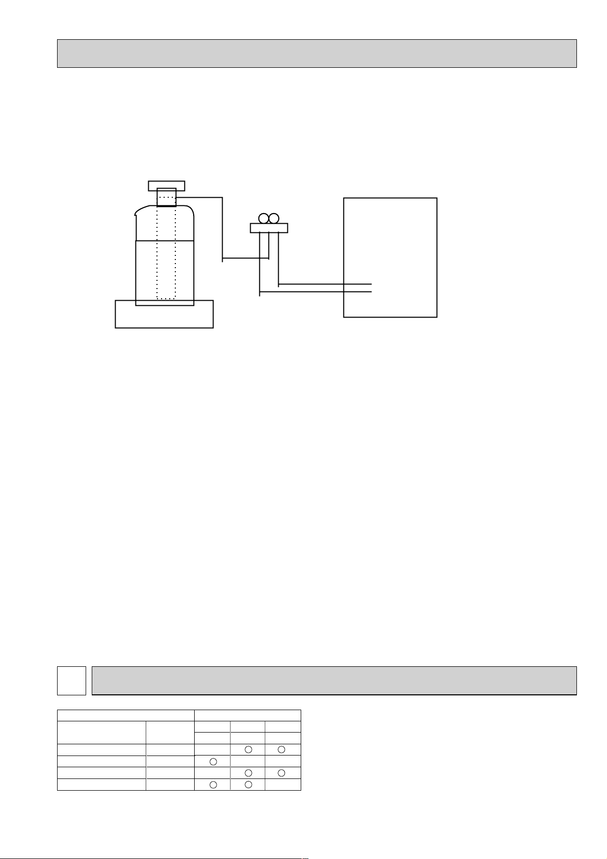
3 COMBINATION OF INDOOR AND OUTDOOR UNITS
Indoor unit Outdoor unit
Service Ref.
PLH-GKH(S)BFT
PLH-KKHCFT
PCH-GKH(S)AFT
PKH-FKHAFT
OC096
OC123
OC135
OC130
Service
Manual No.
1.6
VKAFT
—
—
3
VKAFT
—
5
YKAFT
—
—
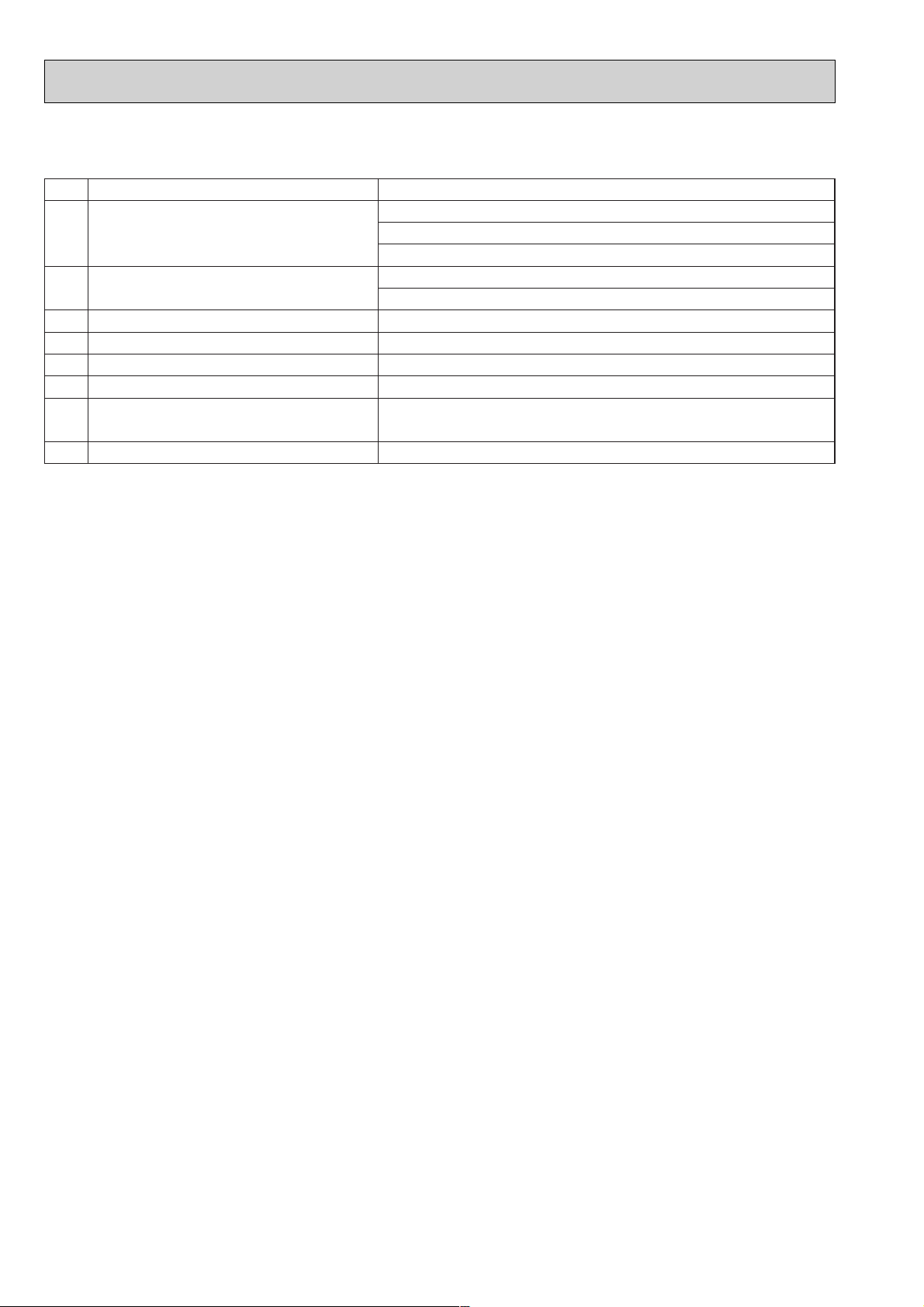
[3] Refrigerant recharging
(1) Refrigerant recharging process
1Direct enclosure from the bomb.
·Comfirm that R407C bomb on the market are syphon pipe.
·Leave the syphon pipe bomb raising and recharge it.
(By liquid refrigerant)
(2) Recharge in refrigerant leakage case
·After recovering the all refrigerator in the unit, proceed to working.
·Do not release the refrigerant in the air.
·After complete the repair service, recharge the cycle with the specified amount of the
liquid refrigerant.
Gravimeter
Unit
Page 6
6
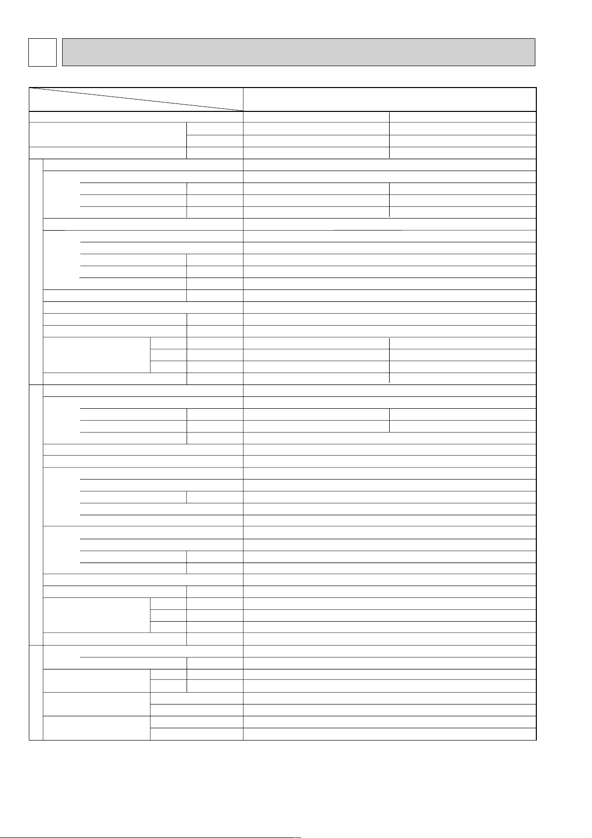
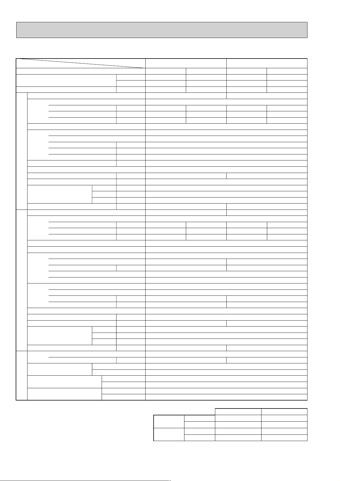
SPECIFICATIONS4
Service Ref.
Item
Btu/h
W
kW
kW
A
A
kW
K/min(CFM)
mmAq,Pa
kW
dB(A)
mm,(in.)
mm,(in.)
mm,(in.)
mm,(in.)
kg,(lbs)
kW
A
A
kW
kW
K
/min(CFM
)
dB(A)
mm,(in.)
mm,(in.)
mm,(in.)
kg,(lbs)
kg,(lbs)
mm,(in.)
mm,(in.)
Function
Capacity
Total input
Service Ref.
Power supply(phase, cycle,voltage)
Input
Running current
Starting current
External finish
Heat exchanger
Fan(drive) x No.
Fan motor output
Airflow(Low-High)
External static pressure
Booster heater
Operation control & Thermostat
Noise level(Low-High)
Cond. drain conn. O.D.
Dimensions
Weight
Service Ref.
Power supply (phase, cycle, voltage)
Input
Running current
Starting current
External finish
Refrigerant control
Compressor
Model
Motor output
Starter type
Protection devices
Heat exchanger
Fan(drive) x No.
Fan motor output
Airflow
Defrost method
Noise level
Dimensions
Weight
Refrigerant
Charge
Pipe size O.D.
Connection method
Between the indoor &
outdoor unit
INDOOR UNITOUTDOOR UNIT
REFRIGERANT PIPING
PLH-1.6KKHCFT
Cooling
15,000
4,400
1.59
0.15
0.64
0.70
UNIT : 660(26)
UNIT : 660(26)
UNIT : 253(10)
UNIT : 19(42)[20(44)]
1.44
6.74
Heating
15,900[20,600]
4,650[6,050]
1.51[3.20]
0.10[1.50]
0.45[6.28]
0.50[6.91]
PANEL : 760(30)
PANEL : 760(30)
PANEL : 30(1-1/8)
PANEL : 3.7(8)[3.7(8)]
1.41
6.60
W
D
H
W
D
H
Liquid
Gas
Indoor side
Outdoor side
Height difference
Piping length
PLH-1.6KKHCFT
Single, 50Hz, 220-240V
Galvanized sheets with gray heat insulation
Plate fin coil
Turbo fan [direct) x 1
0.030
13-16(460-565)
0(direct blow)
[1.4]
Remote controller & built-in
32-37
32(1-1/4)
PUH-1.6VKAFT
Single, 50Hz, 220-240V
33
Munsell 5Y 7/1
Capillary tube
Hermetic
RH247VFC
1.2
Line start
Inner thermostat, High pressure switch
Plate fin coil
Propeller (direct) x 1
0.065
45(1,590)
Reverse cycle
49
870(34-1/4)
295+24 (11-5/8 and 1)
650 (25-5/8)
53(117)
R407C
2.3(5.1)
9.52 (3/8)
15.88 (5/8)
Flared
Flared
Max. 40m
Max. 40m
4.1.Indoor unit
Page 7
7
Service Ref.
Power supply(phase, cycle,voltage)
External finish
Heat exchanger
Booster heater
Operation control & Thermostat
Noise level(Low-High)
Cond. drain conn. O.D.
Dimensions
Weight
Service Ref.
Power supply (phase, cycle, voltage)
External finish
Refrigerant control
Compressor
Heat exchanger
Defrost method
Noise level
Dimensions
Weight
Refrigerant
Pipe size O.D.
Connection method
Between the indoor & outdoor units
Input
Running current
Starting current
Fan(drive) x No.
Fan motor output
Airflow(Low-High)
External static pressure
Input
Running current
Starting current
Model
Motor output
Starter type
Protection devices
Fan(drive) x No.
Fan motor output
Airflow
Charge
W
D
H
W
D
H
Liquid
Gas
Indoor side
Outdoor side
Height difference
Piping length
Function
Capacity
Total input
INDOOR UNITOUTDOOR UNIT
REFRIGERANT
PIPING
Item
Models
Btu/h
W
kW
kW
A
A
kW
K/ min (CFM)
Pa(mmAq)
kW
dB(A)
mm,(in)
mm,(in)
mm,(in)
mm,(in)
kg,(lbs)
kW
A
A
kW
kW
K/ min (CFM)
dB(A)
mm,(in)
mm,(in)
mm,(in)
kg,(lbs)
kg,(lbs)
mm,(in)
mm,(in)
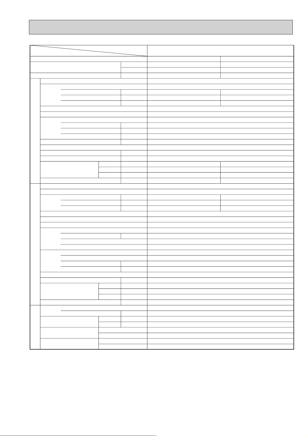
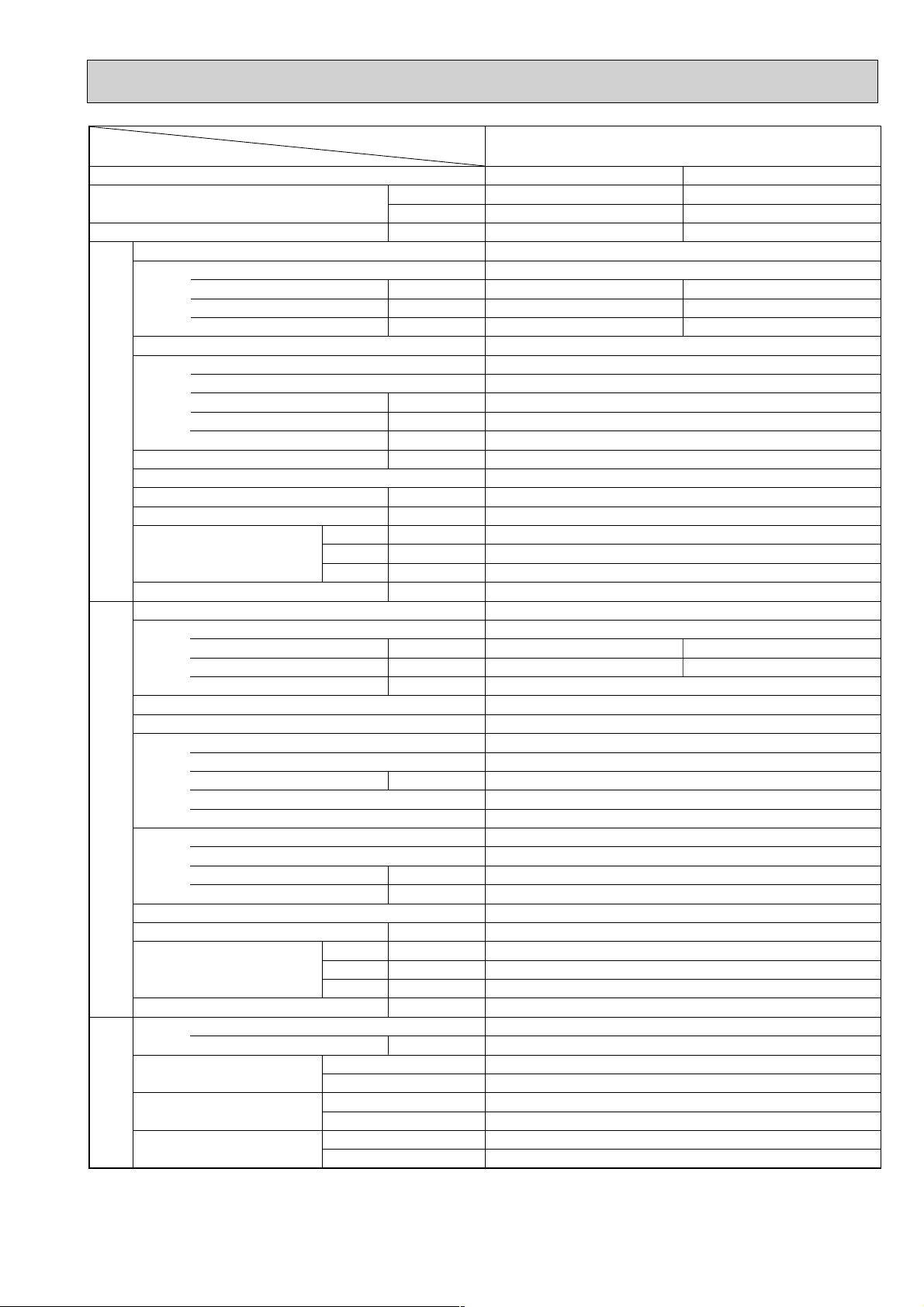
PLH-3GKHBFT
Cooling
26,300
7,700
3.57
Heating
28,700[35,800]
8,400[10,500]
3.59[5.69]
0.16
0.72
1.00
0.16[2.26]
0.72[9.5]
1.00[9.8]
UNIT : 820(32-1/4)
UNIT : 820(32-1/4)
UNIT : 258(10-1/8)
UNIT : 29(64)
PANEL : 950(37-3/8)
PANEL : 950(37-3/8)
PANEL : 65(2-9/16)
PANEL : 7(16)
3.41
4.96/15.58
58/37
3.43
5.04/5.61
58/37
PLH-3GKHBFT
Single, 50Hz, 220-240V
Galvanized sheets with gray heat insulation
Plate fin coil
Turbo fan (direct) x 1
0.050
14-18(495-640)
0(direct blow)
[2.1]
Remote controller & built-in
32-39
30(1-1/4)
PUH-3VKAFT
Single, 50Hz, 220-240V/3, 50Hz, 380-415V(4wires)
Munsell 5Y 7/1
Capillary tube
Hermetic
NE-52VND
2.2/2.4
Line start
w1
Plate fin coil
Propeller (direct) x1
0.085
50(1764)
Reverse cycle
52
870(34-1/4)
295+24 (11-5/8 add 1)
850(34-1/4)
75(165)
R407C
3.2(7.1)
9.52 (3/8)
15.88(5/8)
Flared
Flared
Max. 50m
Max. 50m
w1 V…Internal Thermostat, HP switch
Y…Anti-phase protector, thermal relay, thermal switch, HP switch
Page 8
8
Service Ref.
Power supply(phase, cycle,voltage)
External finish
Heat exchanger
Booster heater
Operation control & Thermostat
Noise level(Low-High)
Cond. drain conn. O.D.
Dimensions
Weight
Service Ref.
Power supply (phase, cycle, voltage)
External finish
Refrigerant control
Compressor
Heat exchanger
Defrost method
Noise level
Dimensions
Weight
Refrigerant
Pipe size O.D.
Connection method
Between the indoor & outdoor units
Input
Running current
Starting current
Fan(drive) x No.
Fan motor output
Airflow(Low-High)
External static pressure
Input
Running current
Starting current
Model
Motor output
Starter type
Protection devices
Fan(drive) x No.
Fan motor output
Airflow
Charge
W
D
H
W
D
H
Liquid
Gas
Indoor side
Outdoor side
Height difference
Piping length
Function
Capacity
Total input
INDOOR UNITOUTDOOR UNIT
REFRIGERANT
PIPING
Item
Models
Btu/h
W
kW
kW
A
A
kW
K/ min (CFM)
Pa(mmAq)
kW
dB(A)
mm,(in)
mm,(in)
mm,(in)
mm,(in)
kg,(lbs)
kW
A
A
kW
kW
K/ min (CFM)
dB(A)
mm,(in)
mm,(in)
mm,(in)
kg,(lbs)
kg,(lbs)
mm,(in)
mm,(in)
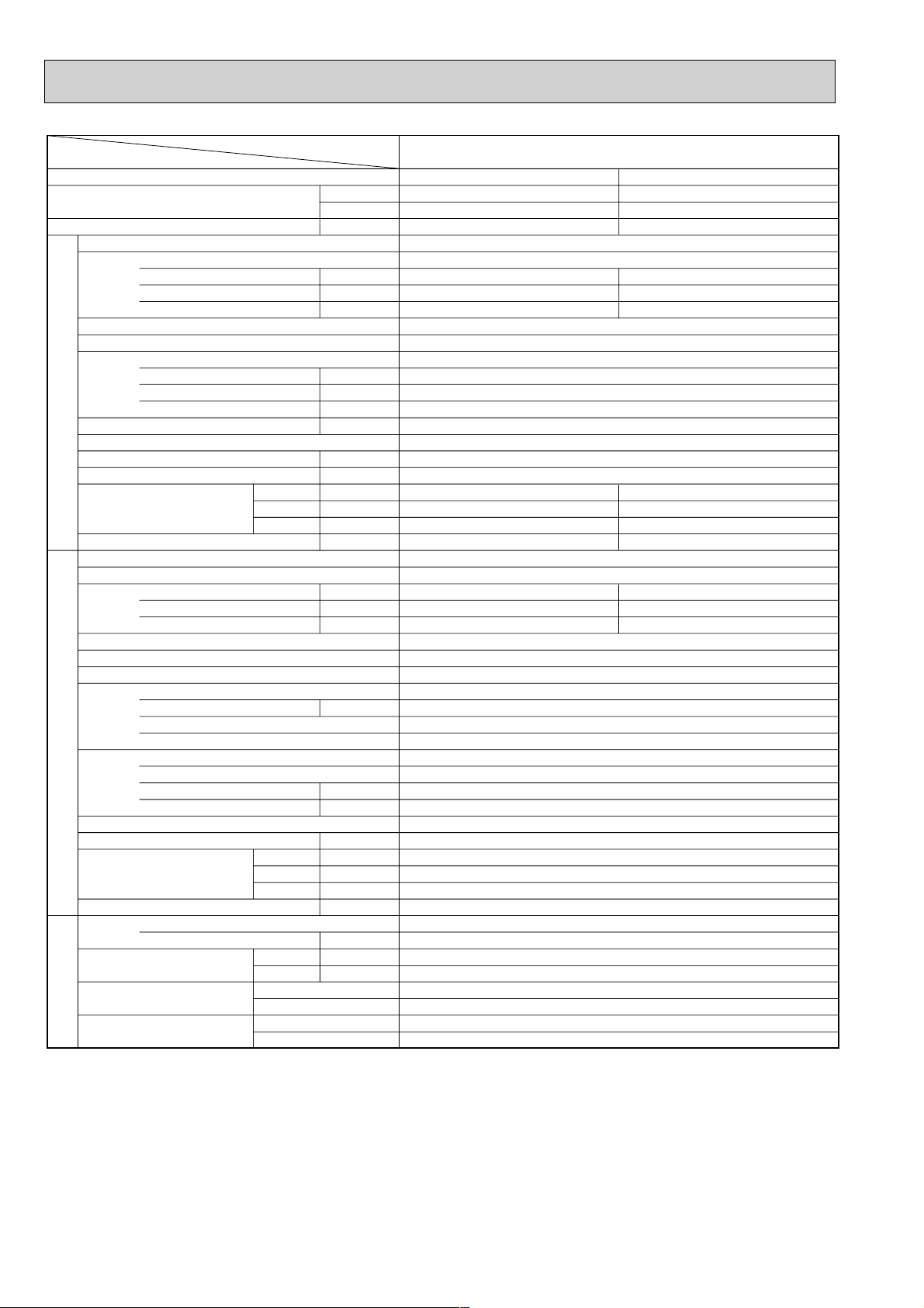
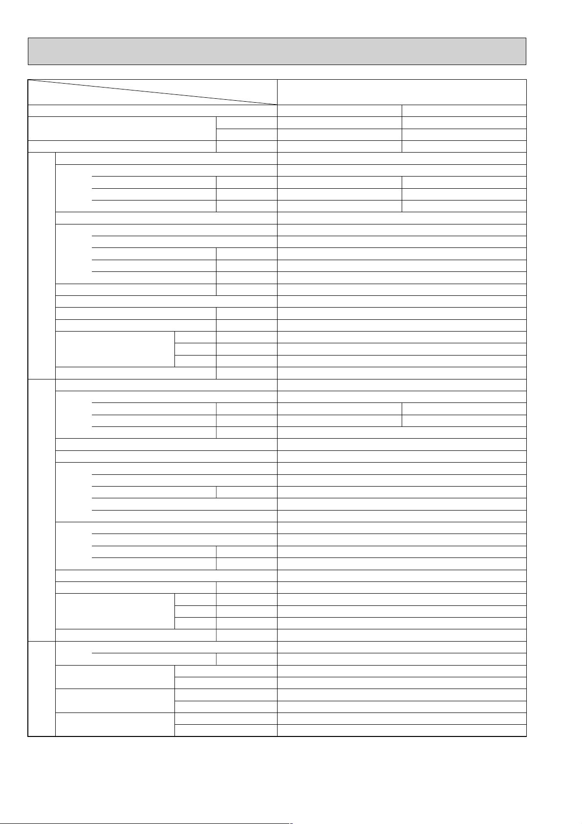
PLH-5GKHSBFT
Cooling
41,300
12,100
4.55
Heating
45,700[56,000]
13,400[16,400]
4.77[7.77]
0.28
1.27
1.50
0.28[3.28]
1.27[13.8]
1.50[14.0]
UNIT : 1340(52-3/4)
UNIT : 820(32-1/4)
UNIT : 258(10-1/8)
UNIT : 45(99)
PANEL : 1470(57-7/8)
PANEL : 950(37-3/8)
PANEL : 65(2-9/16)
PANEL :10(22)
4.27
6.90
53
4.49
7.34
53
PLH-5GKHSBFT
Single, 50Hz, 220-240V
Galvanized sheets with gray heat insulation
Plate fin coil
Turbo fan (direct) x 2
0.050+0.050
24-33(850-1165)
0(direct blow)
[3.0]
Remote controller & built-in
36-43
30(1-1/4)
PUH-5YKSAFT
3, 50Hz, 380-415V(4wire)
Munsell 5Y 7/1
Capillary tube
Hermetic
ZR61KCE-TFD
3.5
Line start
Internal thermostat, Anti-phasa protector, Thermal switch, HP switch
Plate fin coil
Propeller (direct) x2
0.085+0.085
95(3550)
Reverse cycle
55
970(38-3/16)
345+24(13-9/16 add 1)
1258(49-1/2)
114(251)
R407C
5.4(11.9)
9.52(3/8)
19.05(3/4)
Flared
Flared
Max. 50m
Max. 50m
Page 9
9
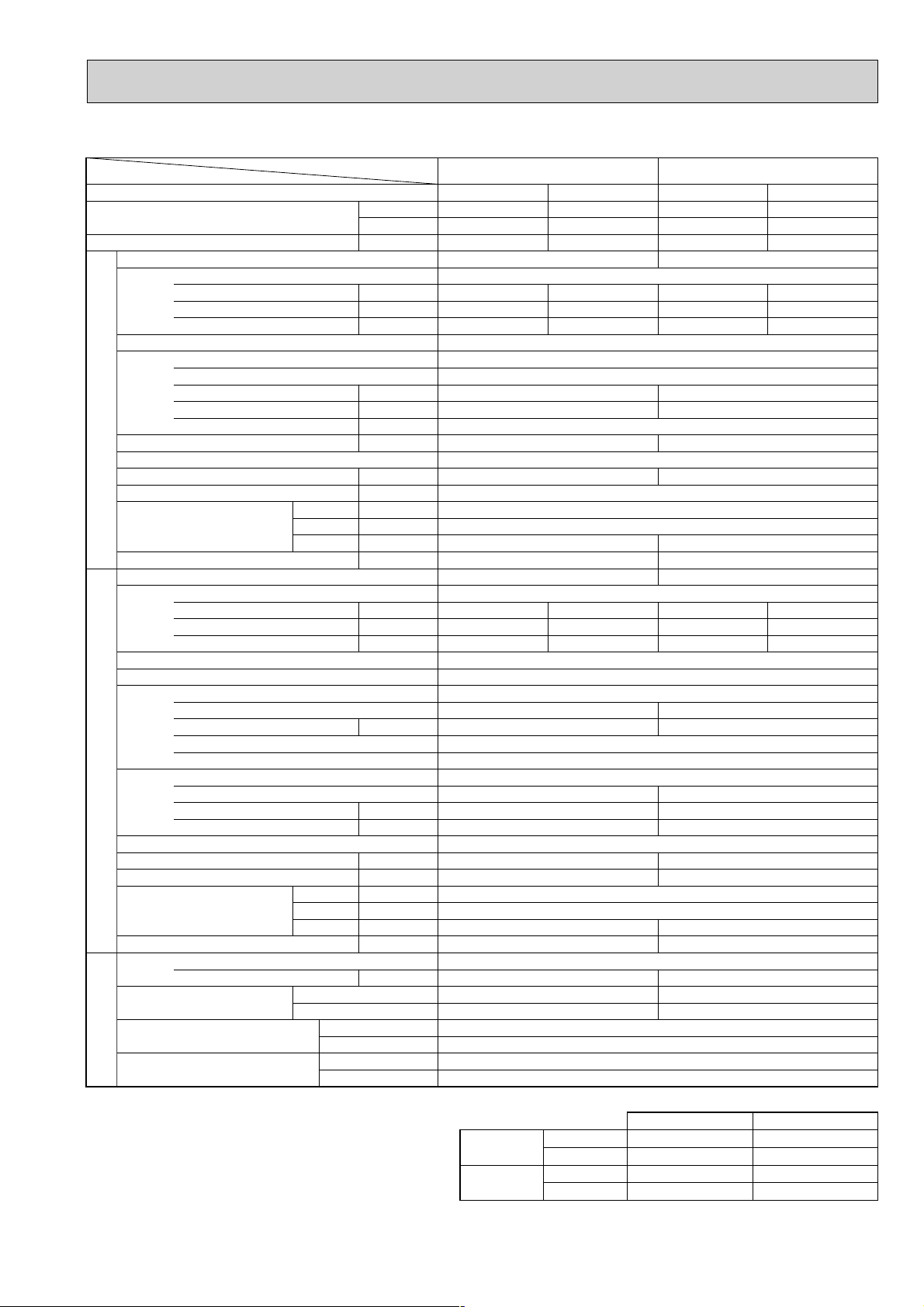
Rating Conditions (JIS B8616)
Service Ref.
Power supply
External finish
Heat exchanger
Booster heater
Operation control & Thermostat
Noise level(Low-High)
Cond. drain connection O.D.
Dimensions
Weight
Service Ref.
Power supply
External finish
Refrigerant control
Compressor
Heat exchanger
Defrost method
Crankcase heater
Noise level
Dimensions
Weight
Refrigerant
Pipe size O.D.
Connection method
Between the indoor & outdoor unit
Indoor side
Outdoor side
Height difference
Piping length
Input
Running current
Starting current
Fan(drive))No.
Fan motor output
Airflow(Low-High)
External static pressure
Input
Running current
Starting current
Model
Motor output
Starter type
Protection devices
Fan(drive))No.
Fan motor output
Airflow
Charge
dB(A)
mm,(in)
mm,(in)
mm,(in)
mm,(in)
kg,(lbs)
W
D
H
Function
Total input
Capacity
Cooling
Heating
Upper limit
Lower limit
Upper limit
Lower limit
Indoor
35: DB, 22.5: WB
21: DB, 15.5: WB
27: DB
20: DB
Outdoor
46: DB
-5: DB
21: DB, 15.5: WB
-8.5: DB, -9.5: WB
2. Guaranteed operating range
W
dB(A)
mm,(in)
mm,(in)
mm,(in)
kg,(lbs)
W
D
H
INDOOR UNITOUTDOOR UNIT
REFRIGERANT
PIPING
Item
Service Ref.
Btu/h
W
kW
kW
A
A
kW
A
A
kW
kg,(lbs)
kW
K/min <CFM>
kW
K/min <CFM>
Pa(mmAq)
kW
mm,(in)
mm,(in)
Liquid
Gas
PCH-3GKHAFT PCH-4GKHSA1
Cooling
25,600
7,500
3.28
0.13
0.55
1.27
0.13 (2.23)
0.55 (9.30)
1.27 (10.02)
0.16
0.70
1.48
0.16 (2.86)
0.70 (11.95)
1.48 (12.73)
Heating
29,000 (36,200)
8,500 (10,600)
3.07 (5.17)
Cooling
34,100
10,000
3.36
Heating
35,700 (44,900)
10,450 (13,150)
3.35(6.05)
PCH-3GKHAFT
Single phase. 50Hz. 220-240V
Munsell 0.70Y 8.59 / 0.97
Plate fin coil
Sirocco (direct) ✕ 3
PCH-4GKHSA
1
0.07
14 -18 <494-635>
0.09
20 -25 <706-883>
0 (direct blow)
(2.1)
210 (8-1/4) 270 (10-5/8)
(2.7)
Remote controller & built-in
37 - 43 40 - 45
26 (1)
1,310 ( 51-9/16 )
680 (26-3/4)
36 (79)
PUH-3VKAFT
39.5 (87)
PUH-4YKSA
3
NH52YDA
2.2 / 2.4
NH56YDA
2.7
Propeller (direct) ✕ 1
0.085
50 (1,764)
Propeller (direct) ✕ 2
0.065 + 0.065
95 (3,350)
850 (33-7/16)
75 (165)
1,258 (49-1/2)
94 (207)
Max. 50m
Max. 50m
38
52
38
54
3.2 (7.1)
9.52 (3/8)
15.88 (5/8)
4.2 (9.2)
9.52 (3/8)
19.05 (3/4)
VKA...1phase, 50Hz, 220-240V
Reverse cycle
R407C
870 <34-1/4>
295 + 24 <11-5/8 add 1>
Munsell 5Y 7/1
Capillary tube
Hermetic
Line start
VKA...Inner thermostat. High-pressure switch YKA...Anti-phase protector, Thermal relay, Thermal switch, High-pressute switch
Plate fin coil
3.15
13.82 / 5.16
58 / 37
2.94
12.89 / 4.81
58 / 37
3.20
5.24
40
3.19
5.22
40
Flared
Flared
Notes1. Rating Conditions (JIS B8616)
Cooling : Indoor : 27:(80
o
F)DB. 19:(66oF)WB
Outdoor : 35:(95
o
F)DB. 24:(75oF)WB
Heating : Indoor : 20:(68
o
F)
Outdoor : 7:(45
o
F)DB. 6:(43oF)WB.
Refrigerant piping length (one way) : 5m(16ft)
3. Above data based on indicated voltage
Indoor Unit 1 phase 240V 50Hz
Outdoor Unit 1 phase 240V 50Hz / 3 phase 415V 50Hz
Page 10
10
Rating Conditions (JIS B8616)
Service Ref.
Power supply
External finish
Heat exchanger
Booster heater
Operation control & Thermostat
Noise level(Low-High)
Cond. drain connection O.D.
Dimensions
Weight
Service Ref.
Power supply
External finish
Refrigerant control
Compressor
Heat exchanger
Defrost method
Crankcase heater
Noise level
Dimensions
Weight
Refrigerant
Pipe size O.D.
Connection method
Between the indoor & outdoor unit
Indoor side
Outdoor side
Height difference
Piping length
Input
Running current
Starting current
Fan(drive))No.
Fan motor output
Airflow(Low-High)
External static pressure
Input
Running current
Starting current
Model
Motor output
Starter type
Protection devices
Fan(drive))No.
Fan motor output
Airflow
Charge
dB(A)
mm,(in)
mm,(in)
mm,(in)
mm,(in)
kg,(lbs)
W
D
H
Function
Total input
Capacity
Cooling
Heating
Upper limit
Lower limit
Upper limit
Lower limit
Indoor
35: DB, 22.5: WB
21: DB, 15.5: WB
27: DB
20: DB
Outdoor
46: DB
-5: DB
21: DB, 15.5: WB
-8.5: DB, -9.5: WB
2. Guaranteed operating range
W
dB(A)
mm,(in)
mm,(in)
mm,(in)
kg,(lbs)
W
D
H
INDOOR UNITOUTDOOR UNIT
REFRIGERANT
PIPING
Item
Service Ref.
Btu/h
W
kW
kW
A
A
kW
A
A
kW
kg,(lbs)
kW
K/min <CFM>
kW
K/min <CFM>
Pa(mmAq)
kW
mm,(in)
mm,(in)
Liquid
Gas
PCH-5GKHSAFT PCH-6GKHSA1
Cooling
42,300
12,400
4.45
0.24
1.06
2.20
0.24 (3.24)
1.06 (13.56)
2.20 (14.70)
0.24
1.06
2.20
0.24 (3.24)
1.06 (13.56)
2.20 (14.70)
Heating
47,400 (57,700)
13,900 (16,900)
4.40 (7.40)
Cooling
49,500
14,500
4.97
Heating
51,200 (61,400)
15,000 (18,000)
4.82 (7.82)
PCH-5GKHSAFT
Single phase. 50Hz. 220-240V
PCH-6GKHSA
1
Munsell 0.70Y 8.59 / 0.97
Plate fin coil
Sirocco (direct)✕4
0.15
27 -34 <953-1,200>
0 (direct blow)
(3.0)
Remote controller & built-in
41-46 42-48
26 (1)
1,620 (63-3/4)
680 (26-3/4)
270 (10-5/8)
46 (101)
PUH-5YSAFT
48 (106)
PUH-6YKSA
2
ZR61KC-ETED
3.5
ZR68KC-TFD
4.0
0.085 + 0.085
95 (3,350)
0.10 + 0.10
100 (3,530)
114 (251) 117 (258)
55 56
5.4 (11.9) 5.0 (11.0)
3 phases. 50Hz. 380-415V (4 wires)
Reverse cycle
38
R407C
970 (38-3/16)
345 + 24 (13-9/16 add 1)
1,258 (49-1/2)
Munsell 5Y 7/1
Capillary tube
Hermetic
Line start
Anti-phase protector, Internal thermostat, Thermal switch, High-pressure switch
Plate fin coil
Propeller (direct)✕2
4.21
6.89
53
4.16
6.81
53
4.73
7.74
74
4.58
7.50
74
9.52 (3/8)
19.05 (3/4)
Flared
Flared
Max. 50m
Max. 50m
Notes1. Rating Conditions (JIS B8616)
Cooling : Indoor : 27:(80
o
F)DB. 19:(66oF)WB
Outdoor : 35:(95
o
F)DB. 24:(75oF)WB
Heating : Indoor : 20:(68
o
F)DB.
Outdoor : 7:(45
o
F)DB. 6:(43oF)WB.
Refrigerant piping length (one way) : 5m(16ft)
3. Above data based on indicated voltage
Indoor Unit 1 phase 240V 50Hz
Outdoor Unit 3 phase 415V 50Hz
Page 11
11
Item
Function
Capacity
Total input
Service Ref.
Power supply(phase,cycle,voltage)
External finish
Heat exchanger
Booster heater
Operation control & Thermostat
Noise level(Low-High)
Cond. drain connection. O.D.
Dimensions
Weight
Service Ref.
Power supply (phase, cycle, voltage)
External finish
Refrigerant control
Compressor
Heat exchanger
Defrost method
Noise level
Dimensions
Weight
Refrigerant
Pipe size O.D.
Connection method
Between the indoor & outdoor unit
Input
Running current
Starting current
Fan(drive) ✕ No.
Fan motor output
Airflow(Low-High)
External static pressure
Input
Running current
Staring current
Model
Motor output
Starter type
Protection devices
Fan(drive)✕No.
Fan motor output
Airflow
Charge
Service Ref.
W
D
H
W
D
H
Liquid
Gas
Indoor side
Outdoor side
Height difference
Piping length
INDOOR UNITOUTDOOR UNIT
REFRIGERANT PIPING
W
Btu/h
kW
kW
A
A
kW
m
3
/X<CFM>
Pa(mmAq)
kW
>(A)
A,<in.>
A,<in.>
A,<in.>
A,<in.>
kg,<lbs>
>(A)
A,<in.>
A,<in.>
A,<in.>
A,<in.>
A,<in.>
kg,<lbs>
kg,<lbs>
kW
A
A
kW
kW
m
3
/X,<CFM>
PKH-1.6FKHAFT
Cooling Heating
4,500 4,650(6,050)
15,350 15,900(20,600)
1.51
0.07
0.32
0.40
PKH-1.6FKHAFT
Single, 50Hz, 220-240V
Munsell 3.4Y 7.7/0.8(White)
Plate fin coil
Line flow(direct) ✕ 1
0.030
10-13<353-459>
0<direct blow>
1.4
Remote controller & built-in
36-43
20<13/16>
1,250<49-3/16>
200<7-7/8>
300<11-13/16>
18<40>
PUH-1.6VKAFT
Single, 50Hz, 220-240V
1.411.44
6.606.74
33
Munsell 5y 7/1
Capillary tube
Hermetic
RE247VFC
1.2
Line start
Internal thermostat, HP switch
Plate fin coil
Propeller (direct) ✕ 1
0.065
45<1,590>
Reverse cycle
49
870<34-1/4>
295+24<11-5/8 add 1>
650<25-5/8>
53<117>
R-407C
2.3<5.1>
9.52<3/8>
15.88<5/8>
Flared
Flared
Max. 40m
Max. 40m
1.48(2.88)
0.07(1.47)
0.32(6.15)
0.40(6.23)
Note. Rating Conditions (JIS B 8616)
Cooling : Indoor : 27°C (80°C) DB, 19°C (66°F) WB
Outdoor : 35°C (95°F) DB, 24°C (75°F) WB
Heating : Indoor : 20°C (68°F)
Outdoor : 7°C (45°F) DB, 6°C (43°F) WB
Page 12
12
Item
Function
Capacity
Total input
Service Ref.
Power supply(phase,cycle,voltage)
External finish
Heat exchanger
Booster heater
Operation control & Thermostat
Noise level(Low-High)
Cond. drain conn. O.D.
Dimensions
Weight
Service Ref.
Power supply (phase, cycle, voltage)
External finish
Refrigerant control
Compressor
Heat exchanger
Defrost method
Noise level
Dimensions
Weight
Refrigerant
Pipe size O.D.
Connection method
Between the indoor & outdoor unit
Input
Running current
Starting current
Fan(drive) ✕ No.
Fan motor output
Airflow(Low-High)
External static pressure
Input
Running current
Staring current
Model
Motor output
Starter type
Protection devices
Fan(drive)✕No.
Fan motor output
Airflow
Charge
Service Ref.
W
D
H
W
D
H
Liquid
Gas
Indoor side
Outdoor side
Height difference
Piping lenghth
INDOOR UNITOUTDOOR UNIT
REFRIGERANT PIPING
W
Btu/h
kW
kW
A
A
kW
m
3
/X<CFM>
Pa(mmAq)
kW
>(A)
A,<in.>
A,<in.>
A,<in.>
A,<in.>
kg,<lbs>
>(A)
A,<in.>
A,<in.>
A,<in.>
A,<in.>
A,<in.>
kg,<lbs>
kg,<lbs>
kW
A
A
kW
kW
m
3
/X<CFM>
PKH-3FKHAFT
Cooling Heating
7,900 9,100(11,200)
27,000 31,000(38,200)
3.25
0.095
0.44
0.80
PKH-3FKHAFT
Single, 50Hz, 220-240V
Munsell 3.4Y 7.7/0.8(White)
Plate fin coil
Line flow(direct) ✕ 2
0.040
15-20<530-706>
0(direct blow)
2.1
Remote controller & built-in
35-43
20<13/16>
1,400<55-1/8>
235<9-1/4>
340<13-3/8>
26<57>
PUH-3VKAFT
Single, 50Hz, 220-240V/3
2.94/2.943.15/3.15
12.89/4.8113.82/5.16
58/37
Munsell 5Y 7/1
Capillary tube
Hermetic
NE52VND
2.2
Line start
Internal thermostat, HP switch/Thermal relay, thermal switch
Plate fin coil
Propeller (direct) ✕ 1
0.085
50<1,764>
Reverse cycle
52
870(34-1/4)
295+24<11-5/8 add 1>
850<33-7/16>
75<165>
R-407C
3.2<7.1>
9.52<3/8>
15.88<5/8>
Flared
Flared
Max. 50m
Max. 50m
3.04(5.14)
0.095(2.195)
0.44(9.19)
0.80(9.55)
Note. Rating Conditions (JIS B 8616)
Cooling : Indoor : 27°C (80°C) DB, 19°C (66°F) WB
Outdoor : 35°C (95°F) DB, 24°C (75°F) WB
Heating : Indoor : 20°C (68°F)
Outdoor : 7°C (45°F) DB, 6°C (43°F) WB
Page 13
13
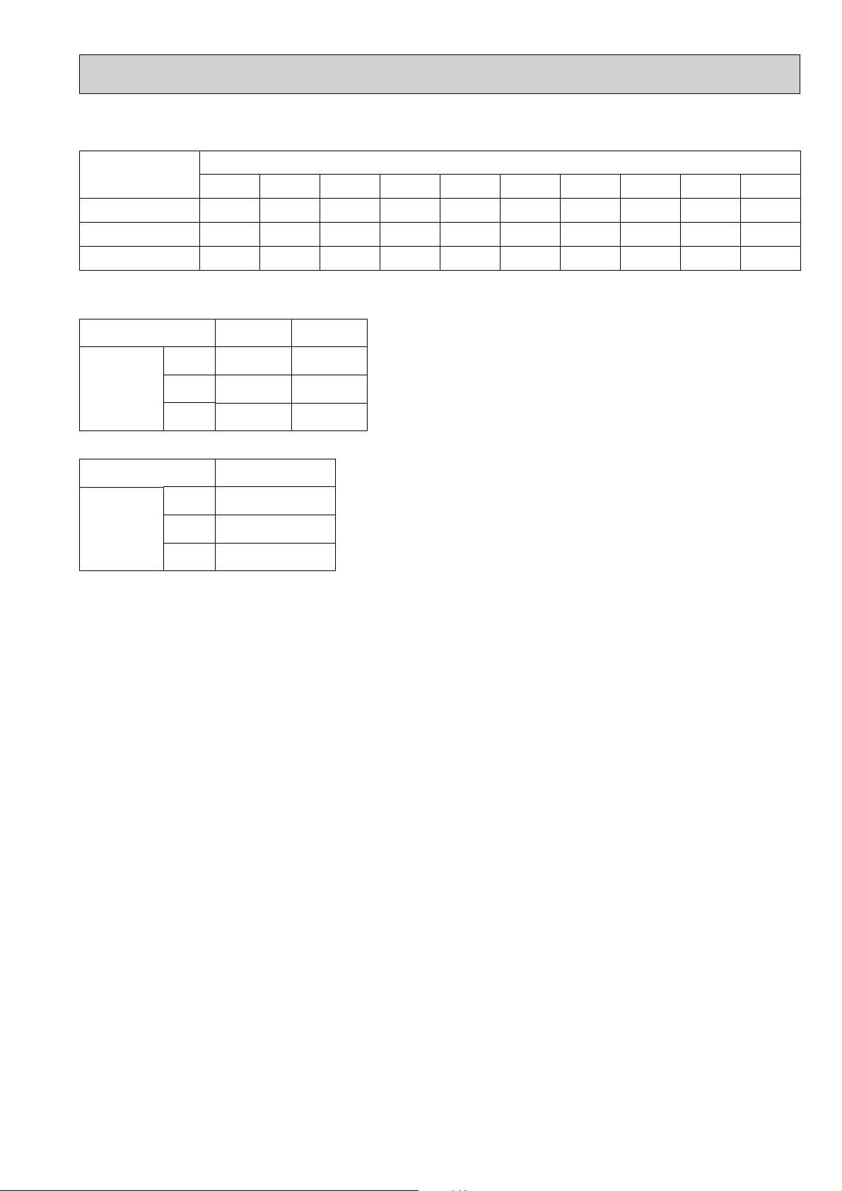
1. REFILLING REFRIGERANT CHARGE (R-22 : kg)
PUH-1.6VKAFT
PUH-3VKAFT
PUH-5YKSAFT
5m
1.6
2.5
4.7
Service Ref.
Refrigerant piping length (one way)
10m
1.8
2.7
4.8
15m
1.9
2.8
5.0
20m
2.0
2.9
5.1
25m
2.2
3.1
5.3
30m
2.3
3.2
5.4
35m
2.4
3.3
5.6
40m
2.5
3.4
5.7
45m
—
3.6
5.9
50m
—
3.7
6.0
2. COMPRESSOR TECHNICAL DATA at 20˚C
at 25˚C
Winding
Resistance
(!)
U-V
(
R-C
)
U-W
(
S-C
)
W-V
Compressor Model
RE247VFC NE52VND
Winding
Resistance
(!)
ZR61KCETED
T1-T2
T2-T3
T3-T1
Compressor Model
4.2.Outdoor unit
Page 14
14
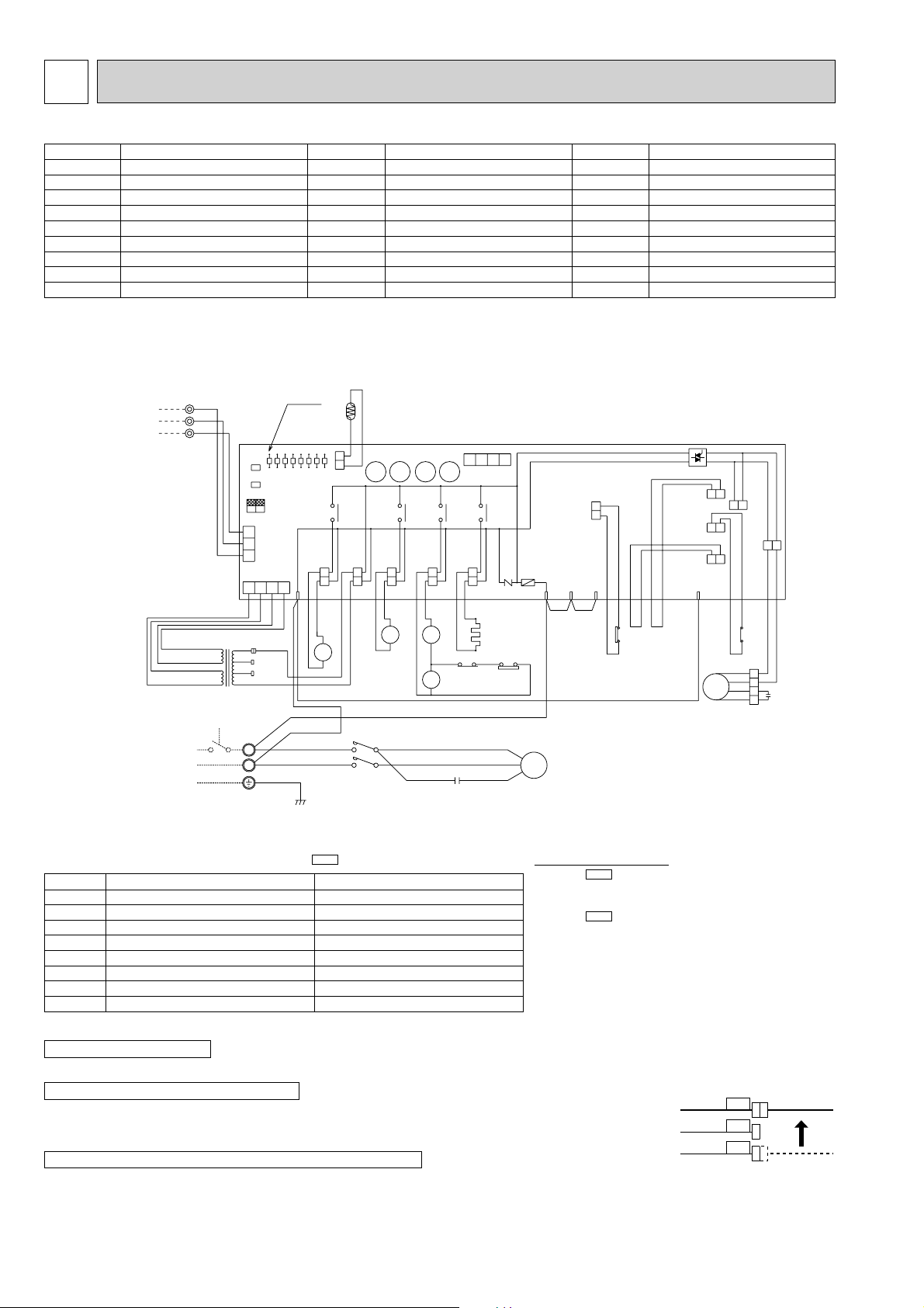
5 WIRING DIAGRAM
PUH-1.6VKAFT
Main functions of LED
(
when both Nos.1 and 2 of are “OFF”
)
NOTE : If the operation stops to function of the protection device, the check display flashes.
●
Connect the lead wires accordling to the color indication of sticker on the compressor terminal.
●
Since LD8 lights when normal power is turned “ON”, check the power supply with the “ON” or “OFF” LD8.
❈
Since the transformer (T) is connected with 240V power, if 220V or 230V power is used, change the wiring connection
in the following procedure.
●
Since the indoor and outdoor connecting wires has polarity, make sure to connect the same terminal numbers (1,2,3) for indoor and outdoor units.
How to use SW1 and 2
●
Pressing erases the past check contents loaded on the
microcomputer.
●
The output display (light) remains lit during operation but
pressing displays the past check contents in flashing
mode. Pressing the switch again returns to output display
(light).
SW3
SW1
SW2
LED No.
LD1
LD2
LD3
LD4
LD5
LD6
LD7
LD8
Output display (light
)
Compressor indoor command
Heating indoor command
63H1 ON
Compressor ON
Outdoor fan ON
4-way valve ON
Bypass valve ON
Crankcase heater ON
Check display (flash
)
–
–
Pipe sensor short/open
63H2 functions
–
–
RT overheat protection
Defective input
CAUTIONS FOR POWER SUPPLY WIRING
CAUTION FOR SERVICING
CAUTION FOR INDOOR AND OUTDOOR CONNECTING WIRES
SYMBOL
MC
MF
C1
C2
RT
HC
52C
21S4
21R
NAME
COMPRESSOR
OUTDOOR FAN MOTOR (INNER THERMOSTAT)
FAN MOTOR CAPACITOR
COMPRESOR CAPACITOR
PIPE TEMP. THERMISTOR
CRANKCASE HEATER
CONTACTOR
4-WAY VALVE SOLENOID COIL
BYPASS VALVE SOLENOID COIL
SYMBOL
TB1,3
63H1
63H2
O.B
ZNR<O.B
>
F<O.B
>
FC<O.B
>
X11<O.B
>
T
NAME
TERMINAL BLOCK
CONTROL HIGH PRESSURE SWITCH
PROTECT HIGH PRESSURE SWITCH
OUTDOOR CONTROLLER BOARD
SURGE ABSORBER
FUSE(6.3A
)
FAN CONTROLLER
CRANKCASE HEATER RELAY
TRANSFORMER
SYMBOL
X12<O.B
>
X13<O.B
>
X14<O.B
>
X16
SW1,2,3<O.B
>
LD1-LD8<O.B
>
NAME
COMPRESSOR RELAY
SOLENOID COIL RELAY
SOLENOID COIL RELEY
HIGH PRESSURE RELAY
CHECK,SERVICE SELECT SWITCH
CHECK,SERVICE LED
TO INDOOR UNIT
CONNECTING WIRES
DC 12V (polar)
POWER SUPPLY
~/N(1phase)
220V-240V 50Hz
1
YLW
2
ORN
3
BRN
TB3
BRN AC12.3V
RED AC12.3V
O.B
SW1
SW2
SW3
12
3
CN3
2
1
CN4T
YLW
240V
ORN
230V
RED
220V
T
TB1
L
N
GRN/YLW
LD1
OFF
ON
LD2
1234
LD3
4
LED
LD4
LD5
LD6
RED
RED
BLU
RT
CN2
LD7
LD8
X14
TRF 52C
SV
WHT
WHT
RED
21R
RED
BLU
52C
L1/1
L3/5
BLU
T1/2
T3/6
X13X14
21S4
BLU
21
S4
GRY
BLU
WHT
RED
GRY
52C
X16
X11X12
A1
A2
GRY
7
8
6
C2
WHT
X16
WHT
CH
CN4
HC
GRY
2
GRY
RED
X11X12X13
ZNR
63H2
1234
F
R/1 S/2 T/3
R
C
MC
S
63H1
BLU BLU
BRN
BRN5YLW
63H1
YLW
YLW
YLW
FC
BLU
26C
63H2
51CM
MF
VLT
BLU
WHT
RED
ORN
VLT
MF2
MF1
1
X16
5
BLU
WHT
4
RED
3
2
C1
1
ORN
❈When power supply is 220V
RED WHITE
220V
ORANGE
YELLOW
230V
240V
Page 15
15
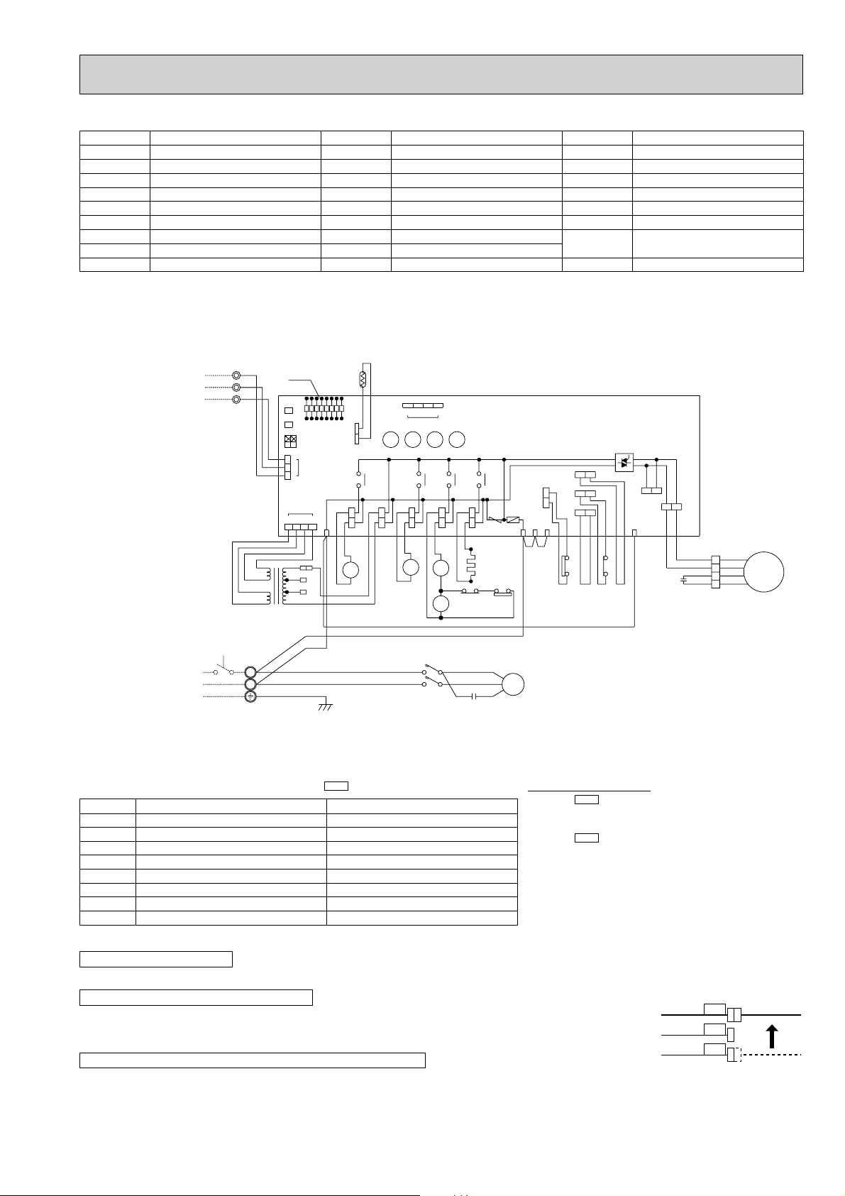
PUH-3VKAFT
Main functions of LED
(
when both Nos.1 and 2 of are “OFF”
)
NOTE : If the operation stops to function of the protection device, the check display flashes.
●
Connect the lead wires accordling to the color indication of sticker on the compressor terminal.
●
Since LD8 lights when normal power is turned “ON”, check the power supply.
❈
Since the transformer (T) is connected with 240V power, if 220V or 230V power is used, change the wiring connection
in the following procedure.
●
Since the indoor and outdoor connecting wires has polarity, make sure to connect the same terminal numbers (1,2,3) for indoor and outdoor units.
How to use SW1 and 2
●
Pressing erases the past check contents loaded on the
microcomputer.
●
The output display (light) remains lit during operation but
pressing displays the past check contents in flashing
mode. Pressing the switch again returns to output display
(light).
SW3
SW1
SW2
LED No.
LD1
LD2
LD3
LD4
LD5
LD6
LD7
LD8
Output display (light
)
Compressor indoor command
Heating indoor command
63H1 ON
Compressor ON
Outdoor fan ON
4-way valve ON
Bypass valve ON
Crankcase heater ON
Check display (flash
)
–
–
Pipe sensor short/open
63H2 functions
–
–
TH overheat protection
Defective input
CAUTIONS FOR POWER SUPPLY WIRING
CAUTION FOR SERVICING
CAUTION FOR INDOOR AND OUTDOOR CONNECTING WIRES
SYMBOL
MC
MF
C1
C2
TH
HC
52C
21S4
21R
NAME
COMPRESSOR
OUTDOOR FAN MOTOR (INNER THERMOSTAT)
FAN MOTOR CAPACITOR
COMPRESOR CAPACITOR
PIPE TEMPERATURE THERMISTOR
CRANKCASE HEATER
CONTACTOR
4-WAY VALVE SOLENOID COIL
BYPASS VALVE SOLENOID COIL
SYMBOL
TB1,3
63H1
63H2
O.B
ZNR<O.B
>
F<O.B
>
FC<O.B
>
X11<O.B
>
T
NAME
TERMINAL BLOCK
CONTROL HIGH PRESSURE SWITCH
PROTECT HIGH PRESSURE SWITCH
OUTDOOR CONTROLLER BOARD
SURGE ABSORBER
FUSE(6.3A
)
FAN CONTROLLER
CRANKCASE HEATER RELAY
TRANSFORMER
SYMBOL
X12<O.B
>
X13<O.B
>
X14<O.B
>
X16
SW1,2,3<O.B
>
LD1-LD8<O.B
>
CN3<O.B
>
CN4T<O.B
>
NAME
COMPRESSOR RELAY
SOLENOID COIL RELAY
SOLENOID COIL RELEY
HIGH PRESSURE RELAY
CHECK,SERVICE SELECT SWITCH
CHECK,SERVICE LED
CONNECTING WIRES
INDOOR/OUTDOOR CONNECTOR
TRANSFORMER CONNECTOR
TO INDOOR UNIT
CONNECTING WIRES
DC 12V
POWER SUPPLY
~/N(1phase)
220V-240V 50Hz
1
YLW
2
ORN
3
BRN
TB3
RED
RED
AC12.3V
AC
12.3V
TB1
L
N
BRN
BRN
T
GRN/YLW
O.B
SW1
SW2
SW3
4
YLW
ORN
RED
LED
12
3
2
1
LD1
OFF
ON
CN3
CN4T
240V
230V
220V
BLU
LD7
LD6
LD5
LD4
LD3
LD2
CN2
123
4
RED
WHT
WHT
TH
LD8
RED
21R
SV
RED
RED
BLU
1234
CN4
X12X13X14
X11
X11X12X13X14
A1
A2
GRY
7
8
WHT
6
BLU
WHT
RED
WHT
X16
C2
CH
GRY
HC
GRY
2
RED
ZNR
63H2
C
TRF
BLU
BLU
L1/1
L3/5
21S4
21
S4
GRY
52C
52C
GRY
52C
X16
T1/2
T2/6
YLW
F. C
MF2
MF1
5
BLU
VLT
VLT
YLW
YLW
1
X16
5
C1
WHT
BLU
RED
ORN
WHT
3
BLU
4
RED
MF
2
ORN
1
26C
63H2
63H1
51CM
ST
F
R
YLW
BRN
BRN
BLUBLU
63H1
R
MC
S
❈When power supply is 220V
RED WHITE
220V
ORANGE
YELLOW
230V
240V
Page 16
16
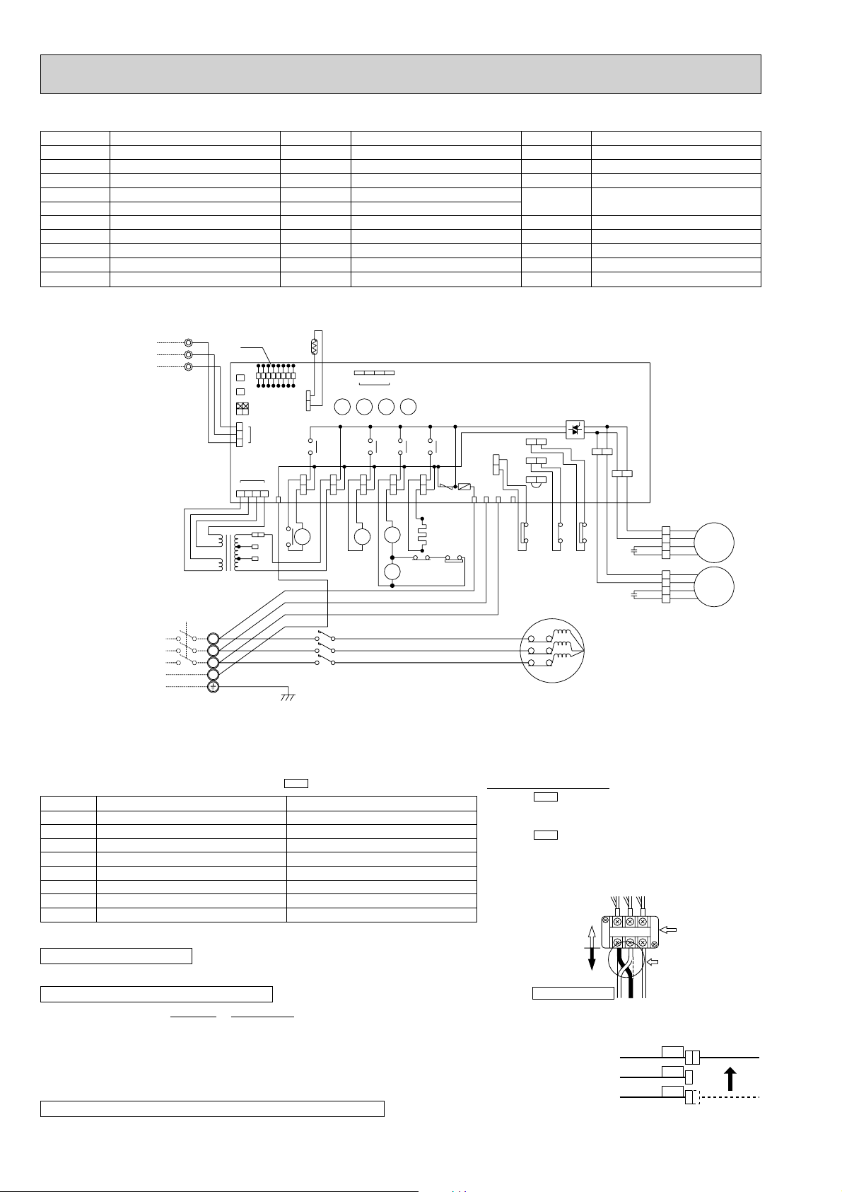
PUH-5YKSAFT
Main functions of LED
(
when both Nos.1 and 2 of are “OFF”
)
NOTE : If the operation stops to function of the protection device, the check display flashes.
●
Connect the lead wires accordling to the color indication of sticker on the compressor terminal.
●
Making wiring connection in anti-phase or missing phase “L2” or “L3” causes the protection device incorporated in the
microcomputer to function resulting in LD1 or LD2 shown in the table above to flash and prevents the compressor
operation. If phase “L1” or “N” is missing it causes all displays to go out. Under normal condition LD8 light when power
is turned “ON”. If anti-phase connection is to be used, change connections of 2 out of 3 power lines (field wiring side)
contained in the power supply terminal block (TB1) of the outdoor unit as shown at the right upper.
❈
Since the transformer (T) is connected with 240V power, if 220V or 230V power is used, change the wiring connection
in the following procedure.
●
Since the indoor and outdoor connecting wires has polarity, make sure to connect the same terminal numbers (1,2,3) for indoor and outdoor units.
How to use SW1 and 2
●
Pressing erases the past check contents loaded on the
microcomputer.
●
The output display (light) remains lit during operation but
pressing displays the past check contents in flashing
mode. Pressing the switch again returns to output display
(light).
SW3
SW1
SW2
LED No.
LD1
LD2
LD3
LD4
LD5
LD6
LD7
LD8
Output display (light
)
Compressor indoor command
Heating indoor command
63H1 ON
Compressor ON
Outdoor fan ON
4-way valve ON
Bypass valve ON
Crankcase heater ON
Check display (flash
)
Auti-phase detect
Missing-phase detect
Pipe sensor short/open
63H2 functions
–
26C functions
RT overheat protection
Defective input
CAUTIONS FOR POWER SUPPLY WIRING
CAUTION FOR SERVICING
CAUTION FOR INDOOR AND OUTDOOR CONNECTING WIRES
SYMBOL
MC
MF1,2
C1,2
TH
HC
49C
52C
21S4
21R
X16
NAME
COMPRESSOR
OUTDOOR FAN MOTOR (INNER THERMOSTAT)
FAN MOTOR CAPACITOR
PIPE TEMPERATURE THERMISTOR
CRANKCASE HEATER
INTERNAL THERMOSTAT FOR MC
CONTACTOR
4-WAY VALVE SOLENOID COIL
BYPASS VALVE SOLENOID COIL
HIGH PRESSURE RELAY
SYMBOL
TB1,3
63H1
63H2
26C
O.B
ZNR<O.B
>
F<O.B
>
FC<O.B
>
X11<O.B
>
T
NAME
TERMINAL BLOCK
CONTROL HIGH PRESSURE SWITCH
PROTECT PRESSURE SWITCH
DIS.CHARGE THERMAL SWITCH
OUTDOOR CONTROLLER BOARD
SURGE ABSORBER
FUSE(6.3A
)
FAN CONTROLLER
CRANKCASE HEATER RELAY
TRANSFORMER
SYMBOL
X12<O.B
>
X13<O.B
>
X14<O.B
>
CN3<O.B
>
CN4T<O.B
>
SW1,2,3<O.B
>
LD1-LD8<O.B
>
51CM<O.B
>
NAME
COMPRESSOR RELAY
SOLENOID COIL RELAY
SOLENOID COIL RELEY
CONNECTING WIRES
INDOOR/OUTDOOR CONNECTOR
TRANSFORMER CONNECTOR
CHECK,SERVICE SELECT SWITCH
CHECK,SERVICE LED
JUMPER CONNECTOR
TO INDOOR UNIT
CONNECTING WIRES
DC 12V
POWER SUPPLY
3N~(3phase 4wires)
380/220V-415/240V 50Hz
YLW
1
ORN
2
BRN
3
TB3
RED
RED
AC
12.3V
AC12.3V
BRN
BRN
TB1
L1
L2
L3
N
LED
O.B
SW1
SW2
SW3
12
3
2
1
CN4T
4
YLW
ORN
RED
T
GRN/YLW
OFF
ON
CN3
LD1
240V
230V
220V
LD5
LD4
LD3
LD2
123
4
13
52C
14
RED
WHT
BLU
TH
LD8
LD7
LD6
CN2
SV
RED
RED
21R
RED
WHT
WHT
RED
WHT
BLK
BLU
L2/3
L3/5
52C
1234
CN4
X11X12X13X14
X11X12X13X14
63H1
RST
F
TRF
T1/2L1/1
T2/4
T3/6
BLU
21S4
BLU
21
S4
52C
GRY
GRY
A1
52C
A2
GRY
X16
ZNR
CH
BLK
BLK
HC
GRY
7
2
6
63H2
X16
8
GRY
RED
WHT
BLU
26C
63H2
51CM
5
BRN
BRN
63H1
49C
T1
T2
T3
VLT
MC
F.C
MF2
MF1
BLK
BLK
VLT
1
X16
26C
5
C1
C2
WHT
BLU
RED
ORN
WHT
BLU
BRN
YLW
WHT
3
BLU
4
RED
2
ORN
1
WHT
3
BLU
4
RED
2
ORN
1
MF1
MF2
Power line reconnection procedure
In case of reverse rotation
Unit side
wiring
Field wiring
Change thie side
L1L2L3
123
charge 2 out of 1.
2 and 3.
(This example shows
reconnection of 1
and 2.)
❈When power supply is 220V
RED WHITE
220V
ORANGE
YELLOW
230V
240V
Outdoor unit
terminal
Page 17
17
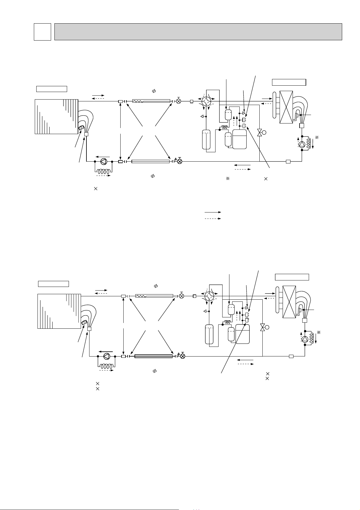
6 REFRIGERANT SYSTEM DIAGRAM
PKH-1.6FKHAFT/PUH-1.6VKAFT
PKH-3FKHAFT/PUH-3VKAFT
Unit : mm
Indoor
heat
exchanger
Indoor coil
thermistor
(RT2)
Distributor
with
strainer
PLH-1.6 (O.D.3.2 I.D.1.6-r630)
Restrictor
valve
Refrigerant pipe
(option)
9.52mm( 3.8")
(with heat insulator)
Ball valve
(with service port)
Indoor unit
Strainer
Refrigerant pipe
(option)
15.88mm( 5/8")
(with heat insulator)
Flexible tube
Flared
connection
Ball valve
Strainer
4-way valve
Oil separator
Service
port
High pressure
control switch
Outdoor unit
Outdoor heat exchanger
Outdoor coil
thermistor
(TH)
Bypass
valve
Restrictor
valve
Capillary
tube
Strainer
Compressor
Accumulator
Refrigerant flow in cooling
Refrigerant flow in heating
R.V.coil
Heating ON
Cooling OFF
PUH-1.6 (O.D.3.2 I.D.1.8 -R600)
Capillary
tube
High pressure
protect switch
Service
port
PLH-1.6KKHCFT/PUH-1.6VKAFT
Indoor unit
Indoor
heat
exchanger
Strainer
Indoor coil
thermistor
(RT1)
Distributor
with
strainer
PKH-1.6 (O.D.3.2 I.D.1.6-r700)
PKH-3 (O.D.4.0 I.D.2.2-r740)
Restrictor
valve
Capillary
tube
Refrigerant pipe
(option)
15.88mm( 5/8")
(with heat insulator)
Flexible tube
Flared
connection
Refrigerant pipe
(option)
9.52mm( 3.8")
(with heat insulator)
Ball valve
Strainer
Service
port
Accumulator
Ball valve
(with service port)
High pressure
Oil separator
4-way valve
Compressor
High pressure
control switch
PUH-1.6 (O.D.3.2 I.D.1.8 -r600)
PUH-3 (O.D.4.0 I.D.2.4 -r940)
control switch
Service
port
Outdoor unit
Outdoor heat exchanger
Bypass
valve
Restrictor
valve
Strainer
Outdoor coil
thermistor
(TH)
Capillary
tube
Page 18

18
Indoor unit
Indoor
heat
exchanger
Refrigerant pipe
(option)
15.88
mm( 5/8")
(with heat insulator)
Flexible tube
Ball valve
Strainer
4-way valve
Oil separator
Service
port
Service
port
High pressure
control switch
High pressure
proted switch
Outdoor unit
Outdoor heat exchanger
Thermistor
TH
Capillary
tube
Restrictor
valve
PUH-3 4.0 2.4- 940
Strainer
Bypass
valve
Compressor
Accumulator
Ball valve
(with service port)
Refrigerant pipe
(option)
9.52
mm( 3/8")
(with heat insulator)
Capillary
tube
Restrictor
valve
Distributor
with
strainer
Thermistor
TH2
Strainer
Flared
connection
Refrigerant flow in cooling
Refrigerant flow in heating
<R.V.coil>
Heating ON
Cooling OFF
Unit : mm
O.D. I.D. Length
O.D. I.D. Length
2.2- 850 PLH-3 4.0
Thermal switch
Indoor unit
Indoor
heat
exchanger
Refrigerant pipe
(option)
19.05
mm( 3/4")
(with heat insulator)
Flexible tube
Ball valve
Strainer
4-way valve
Oil
separator
Service
port
Service
port
High pressure
control switch
High pressure
proted switch
Outdoor unit
Outdoor heat exchanger
Thermistor
TH
Capillary tube
Restrictor
valve
Strainer
Bypass
valve
Compressor
Accumulator
Ball valve
(with service port)
Refrigerant pipe
(option)
9.52
mm( 3/8")
(with heat insulator)
Capillary
tube
Distributor
with
strainer
Thermistor
RT2
Strainer
Flared
connection
PLH-5 4.0 2.6- 690
Capillary tube
O.D. I.D. Length
O.D. I.D. Length
PUH-5 ( 4.0 2.4- 840) 2
Restrictor valve
PLH-3GKHBFT/PUH-3VKAFT
PLH-5GKHSBFT/PUH-5YKSAFT
Page 19

19
Indoor unit
Indoor
heat
exchanger
Refrigerant pipe
(option)
15.88
mm( 5/8")
(with heat insulator)
Flexible tube
Ball valve
Strainer
4-way valve
Oil separator
Service
port
Service
port
High pressure
control switch
Outdoor unit
Outdoor heat exchanger
Outdoor
coil
thermistor
(RT)
Capillary
tube
Restrictor
valve
Strainer
Bypass
valve
Compressor
Accumulator
Ball valve
(with service port)
Refrigerant pipe
(option)
9.52
mm( 3/8")
(with heat insulator)
Capillary
tube
Restrictor
valve
Distributor
with
strainer
Indoor coil
thermistor
RT2
Indoor coil
thermistor
RT2
Strainer
Flared
connection
<R.V.coil>
Heating ON
Cooling OFF
PCH-3(O.D.4.0 ✕ I.D.2.2-R400)
Thermal switch
Indoor unit
Indoor
heat
exchanger
Refrigerant pipe
(option)
19.05
mm( 3/4")
(with heat insulator)
Flexible tube
Ball valve
Strainer
4-way valve
Oil
separator
Service
port
Service
port
High pressure
control switch
Outdoor unit
Outdoor heat exchanger
Capillary
tube
Restrictor
valve
Strainer
Bypass
valve
Compressor
Accumulator
Ball valve
(with service port)
Refrigerant pipe
(option)
9.52
mm( 3/8")
(with heat insulator)
Capillary
tube
Distributor
with
strainer
Strainer
Flared
connection
PCH-5 O.D.4.0 ✕ I.D.2.8-R860
Capillary tube
PUH-5 (O.D.4.0 ✕ I.D.2.4-R840)✕ 2
Restrictor valve
Refrigerant flow in cooling
Refrigerant flow in heating
Unit : mm
PUH-3(O.D.4.0 ✕ I.D.2.4-R940)
Outdoor
coil
thermistor
(RT)
High pressure
protect switch
High pressure
protect switch
(O.D.4.0 ✕ I.D.3.0-R200)
PCH-3GKHAFT/PUH-3VKAFT
PCH-5GKHSAFT/PUH-5YKSAFT
Page 20

20
7 PARTS LIST
PANEL PARTS
PLH-1.6KKHCFT
7
6
No. Part No. Part Name Specification
1
T7W 560 003
2
R01 29H 500
3
R01 29H 691
4
R01 29H 061
5
6
T7W 14K 200
7
T7W 556 305
—
AIR OUTLET GRILLE
AIR FILTER
INTAKE GRILLE
HINGE
GRILLE HANGER
REMOTE CONTROLLER
REMOTE CONTROLLER CABLE
12m
Q'ty/set
PLH-1.6
KKHCFT
1
1
1
2
1
1
1
Remarks
(Drawing No.)
(BG88H096H01)
Wiring
Diagram
Symbol
R.B
Recom-
mended
Q'ty
Unit
Price
Amount
Page 21

21
1
2
3
4
5
6
7
8
9
10
R01 29H 002
R01 29H 085
R01 29H 223
R01 29H 063
T7W 33K 063
R01 29H 056
R01 29H 047
T7W 560 258
R01 29H 040
R01 29H 041
4
1
1
1
1
1
8
1
1
1
MV
H
<3/SET>
AUTO VANE
AIR GUIDE
VANE MOTOR
SPRING JOINT 1
SPRING JOINT
PUSH BUTTON
VANE SUPPORT
CORD HEATER
GRILLE GEAR (RIGHT)
GRILLE GEAR (LEFT)
240V 28.2W
No. Part No. Part Name Specification
Q'ty/set
Price
Unit
Amount
Remarks
(Drawing No.)
Wiring
Diagram
Symbol
Recommended
Q'ty
PLH-1.6
KKHCFT
PANEL PARTS
PLH-1.6KKHCFT
Page 22

22
11
12
13
14
15
37
20
22
3032
34
29 31 33
28
27
26
19
18
7
6
3
4
35
8
9
10
5
1
2
36
24
23
25
16
FUNCTIONAL PARTS
PLH-1.6KKHCFT
21
Page 23

23
1
2
3
4
5
6
7
8
9
11
12
13
14
15
16
17
18
19
20
21
22
23
24
25
26
27
28
29
30
31
32
33
34
35
36
37
38
—
—
—
—
—
T7W E00 762
R01 29H 105
—
R01 41N 114
T7W E00 300
T7W E01 300
R01 32K 706
R01 046 700
R01 08K 202
R01 41N 523
T7W E00 355
R01 W28 266
R01 W28 527
T7W E12 480
R01 E00 529
—
—
T7W 521 716
T7W 517 716
T7W 515 716
R01 29H 255
—
T7W 58K 310
T7W 520 239
T7W 580 799
R01 J07 202
—
—
R01 71G 215
T7W 29H 675
R01 08K 097
R01 A48 524
R01 71N 241
R01 20J 303
MF1
H
H
FS1
26H
RT2
DP
DS
TB2
TB4
TB5
C1
I.B
F.IN
T
RT1
88H
(BG02Y348G06)
(BG00T672G08)
(BG00T672G09)
(BG00T672G10)
(BG00T673G02)
(BG00T718G06)
(BG00T713G05)
(BG00T712G06)
(BG25J542H04)
(BG00L601G22)
(BG00A662G18)
BASE
LEG
LEG
LEG
LEG
FAN MOTOR
MOTOR MOUNT
INNER COVER
TURBO FAN
HEATER ELEMENT
HEATER ELEMENT
THERMAL FUSE
THERMAL SWITCH
INDOOR COIL THERMISTOR
DRAIN SOCKET
DRAIN PUMP
DRAIN SENSOR
DRAIN HOSE
HEAT EXCHANGER
DRAIN PAN
CORNER COVER
COVER (DRAM)
TERMINAL BLOCK
TERMINAL BLOCK
TERMINAL BLOCK
CAPACITOR
CONTROLLER CASE
INDOOR CONTROLLER BOARD
FUSE
TRANSFORMER
ROOM TEMPERATURE THERMISTOR
BELL MOUTH
ELECTRICAL PARTS COVER
RELAY
FAN GUARD
SPL WASHER
DRAIN PLUG
SENSOR HOLDER
INSULATOR
PAI-V30F
467W 240V
700W 240V
77"C 250V 10A
OFF42"C ON32"C
3P(L,N,;)
3P(1,2,3)
2P(1,2)
2.5#F 400V
250V 6.3A
LY2F DC12V
No.
Part No. Part Name Specification
Q'ty/set
Price
Unit Amount
Remarks
(Drawing No.)
Wiring
Diagram
Symbol
Recommended
Q'ty
10
KKHCFT
PLH-1.6
1
1
1
1
1
1
3
1
1
3
1
1
1
1
1
1
1
1
1
1
1
1
1
1
1
1
1
1
1
1
1
1
1
1
1
1
1
1
Part numbers that are cicled are not shown in the figure.
Page 24

24
No. Parts No. Parts Name
Specification
Q'ty / set
PLH-3
GKHBFT
Remarks
(Drawing No.)
Wiring
Diagram
Symbol
Recom-
mended
Q'ty
Unit Amount
Price
1
2
3
4
5
6
7
8
AIR OUTLET GRILLE
AIR FILTER
INTAKE GRILLE
HANGER G
GRILLE CATCH
FILTER CATCH
SHUTTER PLATE
PANEL SCREW
PANEL 1
1
1
1
2
2
1
1
T7W 700 003
R01 W28 500
R01 W28 691
R01 W28 098
R01 W28 054
R01 029 054
R01 W28 083
R01 W28 673
PANEL PARTS
PLH-3GKHBFT
Part numbers that are circled are not shown in the figure.
Page 25

25
No. Parts No. Parts Name
Specification
Q'ty / set
PLH-3
GKHBFT
Remarks
(Drawing No.)
Wiring
Diagram
Symbol
Recom-
mended
Q'ty
Unit Amount
Price
1
2
3
4
5
6
7
8
9
AUTO VANE(2)
AUTO VANE(3)
AIR GUIDE(1)
AIR GUIDE(2)
AIR GUIDE(3)
AIR GUIDE(4)
VANE MOTOR
VANE JOINT
VANE BUSHING
2
2
1
1
1
1
1
4
8
MV
R01 W29 002
R01 W30 002
R01 W28 085
R01 W28 086
R01 W28 087
R01 W28 088
T7W 700 223
R01 W28 063
R01 W28 064
PANEL PARTS
PLH-3GKHBFT
8
9
2
9
8
9
1
9
8
7
9
4
2
6
9
5
9
3
8
Page 26

26
FUNCTIONAL PARTS
PLH-3GKHBFT
37
Page 27

27
No. Parts No. Parts Name Specifications
Q'ty/set
PLH-3
GKHBFT
Remarks
(Drawing No.)
Wiring
Diagram
Symbol
Recommended
Q'ty
Unit Amount
Price
1
2
3
4
5
6
7
8
9
10
11
12
13
14
15
16
17
18
19
20
21
22
23
24
25
26
27
28
29
30
31
32
33
34
35
36
37
BASE
DRAM (1)
DRAM (2)
FAN MOTOR
TURBO FAN
LEG
HEATER ELEMENT
THERMAL FUSE
THERMAL SWITCH
INDOOR COIL THERMISTOR
DRAIN SOCKET
DRAIN PUMP
DRAIN SENSOR
HEAT EXCHANGER
DRAIN PAN
TERMINAL BLOCK
TERMINAL BLOCK
TERMINAL BLOCK
RELAY
TRANSFORMER
RUN CAPACITOR
INDOOR CONTROLLER BOARD
FUSE
CONTROLLER CASE
BELL MOUTH
ROOM TEMPERATURE
THERMISTOR
DRAIN HOSE
ELECTRICAL BOX
ELECTRICAL BOX
REMOTE CONTROLLER
REMOTE CONTROLLER CABLE
MOTOR LEG
RUBBER MOUNT
SPL WASHER
DRAIN PLUG
FAN GUARD
SENSOR HOLDER
1
1
1
1
1
4
3
2
2
1
1
1
1
1
1
1
1
1
1
1
1
1
1
1
1
1
1
1
1
1
1
1
3
1
1
1
1
(BG00C305G25)
(BG00A102G10)
(BG00A101G09)
(DB00H01G02)
(BG25B226H03)
(BG00A894G06)
(BG00D221G19)
(BG00D221G09)
MF1
H1
FS1,2
26H
RT2
DP
DS
TB2
TB4
TB5
88H
T
C1
I.B
F<I.B>
RT1
R,B
PM6V50-LA
240V 700W
250V 96"C 10A
OFF 42"C ON 32"C
3P(L,N,;)
3P(1,2,3)
2P(1,2)
JC-1A DC 12V
3+ 400V
250V 6.3A
12m
—
—
—
T7W 703 762
R01 W46 114
—
T7W 705 300
R01 P02 706
R01 046 700
R01 W28 202
R01 K01 523
T7W 11K 355
R01 W28 266
T7W E10 480
R01 W28 529
T7W 519 716
T7W 518 716
T7W 515 716
R01 71G 215
T7W 700 799
R01 W28 255
T7W 57K 310
T7W 520 239
—
—
R01 J01 202
R01 W28 527
—
—
T7W 14K 200
T7W 556 305
R01 W46 130
R01 W28 105
R01 08K 097
R01 A48 524
T7W 11K 675
R01 005 533
Part numbers that are circled are not shown in the figure.
Page 28

28
FUNCTIONAL PARTS
PLH-5GKHSBFT
38
Page 29

29
PLH-5
No. Parts No. Parts Name Specifications
GKHSBFT
Remarks
(Drawing No.)
Wiring
Diagram
Symbol
Recommended
Q'ty
Unit
Amount
Price
1
2
3
4
5
6
7
8
9
10
11
12
13
14
15
16
17
18
19
20
21
22
23
24
25
26
27
28
29
30
31
32
33
34
35
36
37
38
BASE
DRAM (1)
DRAM (2)
SEPARATOR
FAN MOTOR
TURBO FAN
LEG
HEATER ELEMENT
THERMAL FUSE
THERMAL SWITCH
INDOOR COIL THERMISTOR
DRAIN SOCKET
DRAIN PUMP
DRAIN SENSOR
HEAT EXCHANGER
DRAIN PAN
TERMINAL BLOCK
TERMINAL BLOCK
TERMINAL BLOCK
RELAY
TRANSFORMER
RUN CAPACITOR
INDOOR CONTROLLER BOARD
FUSE
INDOOR CONTROLLER CASE
BELL MOUTH
BELL MOUTH
ROOM TEMPERATURE
THERMISTOR
DRAIN HOSE
ELECTRICAL BOX
ELECTRICAL BOX
REMOTE CONTROLLER
REMOTE CONTROLLER CABLE
MOTOR LEG
RUBBER MOUNT
SPL WASHER
FAN GUARD
DRAIN PLUG
SENSOR HOLDER
1
1
1
2
2
2
4
3
2
2
1
1
1
1
1
1
1
1
1
1
1
2
1
1
1
1
1
1
1
1
1
1
1
2
6
2
2
1
1
(BG00C305G26)
(BG00A102G10)
(BG00A101G09)
(BG00C324G07)
(DB00H010G02)
(BG25B226H03)
(BG00C894G06)
(BG00C894G07)
(BG00D220G13)
(BG00D221G09)
MF1,2
H1
FS1,2
26H
RT2
DP
DS
TB2
TB4
TB5
88H
T
C1,2
I.B
F<I.B>
RT1
R,B
PM6V50-LA
240V 1000W
250V 98"C 15A
OFF 42"C ON 32"C
3P(L,N,;)
3P(1,2,3)
2P(1,2)
JC-1A DC 12V
3+ 400V
250V 6.3A
12m
—
—
—
—
T7W 703 762
R01 W46 114
—
T7W 709 300
T7W 509 706
R01 046 700
R01 W28 202
R01 K01 523
T7W 11K 355
R01 W28 266
T7W E11 480
R01 W50 529
T7W 518 716
T7W 519 716
T7W 515 716
R01 71G 215
T7W 700 799
R01 W28 255
T7W 57K 310
T7W 520 239
—
—
—
R01 J01 202
R01 W28 527
—
—
T7W 14K 200
T7W 556 305
R01 W46 130
R01 W28 105
R01 08K 097
T7W 11K 675
R01 A48 524
R01 005 533
Part numbers that are circled are not shown in the figure.
Page 30

30
PANEL PARTS
PLH-5GKHSBFT
Part numbers that are circled are not shown in the figure.
No. Parts No. Parts Name
Specification
Q'ty / set
PLH-5
Remarks
(Drawing No.)
Wiring
Diagram
Symbol
Recom-
mended
Q'ty
Unit Amount
Price
1
2
3
4
5
6
7
8
AIR OUTLET GRILLE
AIR FILTER
INTAKE GRILLE
HANGER G
GRILLE CATCH
FILTER CATCH
SHUTTER PLATE
PANEL SCREW
PANEL 1
2
2
2
4
4
1
1
T7W 800 003
R01 W50 500
R01 W50 691
R01 W28 098
R01 W28 054
R01 029 054
R01 W50 083
R01 W28 673
GKHSBFT
Page 31

31
No. Parts No. Parts Name
Specification
Q'ty / set
GKHSBFT
PLH-5
Remarks
(Drawing No.)
Wiring
Diagram
Symbol
Recommended
Q'ty
Unit Amount
Price
1
2
3
4
5
6
7
8
9
10
11
AUTO VANE (L1)
AUTO VANE (L2)
AUTO VANE (2)
AUTO VANE (3)
AIR GUIDE (L1)
AIR GUIDE (L2)
AIR GUIDE (3)
AIR GUIDE (4)
VANE MOTOR
VANE JOINT
VANE BUSHING
1
1
1
1
1
1
1
1
1
4
8
MV
R01 W50 002
R01 W51 002
R01 W29 002
R01 W28 002
R01 W50 085
R01 W50 086
R01 W28 087
R01 W28 088
T7W 700 223
R01 W28 063
R01 W28 064
PANEL PARTS
PLH-5GKHSBFT
Page 32

32
STRUCTURAL PART
PCH-3GKHAFT
16
11
13
14 12
27
15
10
24
17
1
5
22252619
7
369
4
23
18
2
8
Page 33

33
No.
Parts No. Parts Name
Specifications
PCH-3
Wiring
Diagram
Symbol
Recom-
mended
Q'ty
Unit
Amount
Q'ty / set Price
1
2
3
4
5
6
7
8
9
10
11
12
13
14
15
16
17
18
19
20
21
22
23
24
25
26
27
RIGHT SIDE PANEL
LEFT SIDE PANEL
L.L. FILTER
REAR PANEL
FRONT PANEL
GRILLE ASSY
UNDER PANEL
GRILLE HINGE
GRILLE CATCH
RIGHT SIDE BOX
LEFT SIDE BOX
GUIDE VANE ASSY-6R.
GUIDE VANE ASSY-6L.
GUIDE VANE ASSY-6C.
AUTO VANE
VANE MOTOR
RIGHT LEG
LEFT LEG
WIRELESS BOARD CASE
JOINT SOCKET
DRAIN HOSECOVER
SIDE PLATE-R.
SIDE PLATE-L.
SERVICE PANEL
BEAM(GA)
REAR SUPPORT
VANE SUPPORT
1
1
2
1
1
2
1
4
4
1
1
1
1
1
1
1
1
1
1
1
1
1
1
1
2
1
2
(BG02H454H08)
(BG02H454H04)
(BG02R321G06)
MV
Remarks
(Drawing No.)
R01 17J 661
R01 17J 662
R01 17J 500
R01 29J 676
R01 29J 651
R01 17J 691
R01 29J 669
R01 17J 061
R01 17J 054
R01 17J 067
R01 17J 068
R01 17J 085
R01 18J 086
R01 29J 087
R01 29J 002
R01 29J 223
R01 17J 808
R01 17J 809
R01 17J 070
R01 17J 523
R01 17J 072
R01 18J 665
R01 18J 666
R01 17J 668
—
—
—
GKHAFT
Page 34

34
STRUCTURAL PART
PCH-5GKHSAFT
20
14 16 12 29 13 11
17
10
24
15
26
1
27
28
21
3
5
79
8
18
4
25
2
6
19
Page 35

35
No.
Parts No. Parts Name
Specifications
Q'ty / set Price
Wiring
PCH-5
GKHSAFT
Remarks
(Drawing No.)
Diagram
Symbol
Recom-
mended
Q'ty
Unit
Amount
R01 35J 661
1
R01 35J 662
2
R01 41J 669
3
R01 41J 676
4
R01 17J 500
5
R01 18J 500
6
R01 17J 691
7
R01 18J 691
8
R01 17J 054
9
R01 41J 651
10
R01 41J 085
11
R01 42J 086
12
R01 43J 087
13
R01 35J 223
14
R01 35J 067
15
R01 35J 068
16
R01 41J 002
17
R01 17J 061
18
R01 17J 808
19
R01 17J 809
20
R01 17J 070
21
R01 17J 523
22
R01 17J 072
23
R01 35J 665
24
R01 35J 666
25
R01 17J 668
26
27
28
29
—
—
—
RIGHT SIDE PANEL
LEFT SIDE PANEL
UNDER PANEL
REAR PANEL
L.L. FILTER
L.L. FILTER
GRILLE ASSY
GRILLE ASSY
GRILLE CATCH
FRONT PANEL
GUIDE VANE ASSY-5R.
GUIDE VANE ASSY-5L.
GUIDE VANE ASSY-5C.
VANE MOTOR
RIGHT SIDE BOX
LEFT SIDE BOX
AUTO VANE
GRILLE HINGE
RIGHT LEG
LEFT LEG
WIRELESS BOARD CASE
JOINT SOCKET
DRAIN HOSE COVER
SIDE PLATE-R.
SIDE PLATE-L.
SERVICE PANEL
BEAM(GA)
REAR SUPPORT
VANE SUPPORT
1
1
1
1
2
1
2
1
4
1
1
1
2
1
MV
1
1
1
4
1
1
1
1
1
1
1
1
3
1
3
(BG17H464H08)
(BG02H454H04)
(BG02R805G04)
Page 36

36
No. Parts No. Parts Name Specifications
PCH-3
Wiring
Diagram
Symbol
Recommended
Q'ty
Unit
Amount
Q'ty / set Price
1
2
3
4
5
6
7
8
9
10
11
12
13
14
15
16
17
18
19
20
21
22
FAN MOTOR
FAN JOINT
SHAFT (FAN)
SLEEVE BEARING
MOTOR LEG
SIROCCO FAN
SIROCCO FAN
CASING
HEATER ELEMENT
THERMAL SWITCH
THERMAL FUSE
INSULATOR
INSULATOR
INDOOR COIL THERMISTOR
ROOM TEMPERATURE
THERMISTOR
HEAT EXCHANGER
DRAIN PAN ASSY
DRAIN PLUG
BEARING SUPPORT
FAN GUARD
FAN GUARD
FAN GUARD
PIECE (MOTOR)
1
1
1
1
1
2
1
3
3
1
1
1
3
1
1
1
1
1
1
1
2
1
1
MF
H
26H
FS1,2
RT2
RT1
Remarks
(Drawing No.)
T7W 30J 762
R01 29J 116
R01 29J 100
R01 705 103
R01 29J 130
R01 29J 114
R01 33J 114
R01 17J 110
T7W 30J 300
R01 46K 700
T7W 23J 706
R01 20J 303
R01 30J 303
R01 17J 202
R01 18J 202
T7W E08 480
R01 29J 529
R01 17J 524
R01 29J 145
T7W 20J 675
T7W 21J 675
T7W 18J 675
R01 43E 126
DC9C4P70MS
80V 700W
OFF:50: ON:35:
110" 15A 250V
GKHAFT
9
13
15
11
10
6
8
21
16
20
3
19
7
17
4·18
14
2
1
5
22
12
FAN AND HEATER PARTS
PCH-3GKHAFT
Page 37

37
17
10
12
4·20
9
23
8
22
18
7
21
19
24
11
6
25
2
3
1
5
16
13
14
15
FAN AND HEATER PARTS
PCH-5GKHSAFT
No.
Parts No. Parts Name Specifications
1
T7W 43J 762
2
R01 29J 116
3
R01 29J 100
4
R01 705 103
5
R01 41J 130
6
R01 41J 114
7
R01 39J 114
8
R01 35J 114
9
R01 35J 110
10
R01 17J 202
11
R01 18J 202
12
T7W 43J 300
13
R01 46K 700
14
T7W 23J 706
15
R01 20J 303
16
R01 36J 303
17
T7W E09 480
18
R01 41J 529
19
R01 17J 524
20
R01 35J 145
21
T7W 25J 675
22
T7W 23J 675
23
T7W 24J 675
24
T7W 26J 675
25
R01 43E 126
FAN MOTOR
FAN JOINT
SHAFT
SLEEVE BEARING
MOTOR LEG
SIROCCO FAN
SIROCCO FAN
SIROCCO FAN
CASING
INDOOR COIL THERMISTOR
ROOM TEMPERATURE THERMISTOR
HEATER ELEMENT
THERMAL SWITCH
THERMAL FUSE
INSULATOR
INSULATOR
HEAT EXCHANGER
DRAIN PAN ASSY
DRAIN PLUG
BEARING SUPPORT
FAN GUARD
FAN GUARD
FAN GUARD
FAN GUARD
PIECE (MOTOR)
D10B4P150MS
80V 1000W
OFF:50: ON:35:
110" 15A 250V
Q'ty / set Price
PCH-5
GKHSAFT
Remarks
(Drawing No.)
1
Wiring
Diagram
Symbol
MF
Recom-
mended
Q'ty
Unit
Amount
1
1
1
1
1
1
2
4
1
1
3
1
1
RT2
RT1
H
26H
FS1
1
6
1
1
1
1
1
2
1
1
1
Page 38

38
No.
Parts No. Parts Name
Specifications
Wiring
Diagram
Symbol
Recom-
mended
Q'ty
Unit
Amount
Q'ty / set Price
1
2
3
4
5
6
7
8
9
10
11
12
CONTROLLER BOARD
FUSE
TRANSFORMER
CONTROL BOX
RUN CAPACITOR
RUN CAPACITOR
TERMINAL BLOCK
TERMINAL BLOCK
TERMINAL BLOCK
BOX COVER
REMOTE CONTROLLER
REMOTE CONTROLLER CORD
RELAY
(BG00N015G14)
(BG02A804G13)
3
1
1
1
1
1
1
1
1
1
1
1
1
5
1
1
1
1
1
1
1
1
1
1
1
1
I.B
F1,2
T
C
C
C
TB2
TB4
R.B
250V 6.3A
4MF. 440V
6MF. 440V
3P (L,N, )
3P (1,2,3)
2P (1,2)
10m
JC-1A DC12V
Remarks
(Drawing No.)
T7W 71J 310
T7W 520 239
T7W 23J 260
T7W 39J 255
T7W 43J 255
T7W 521 716
T7W 517 716
T7W 512 716
T7W 14K 200
R01 08K 305
R01 71G 215
GKHAFT GKHSAFT
5
12
3
2
1
6
7
8
4
10
11
9
ELECTRICAL PARTS
PCH-3GKHAFT
PCH-5GKHSAFT
Page 39

39
STRUCTURAL PARTS
PKH-1.6FKHAFT
1
10
4
10
4
3
25
11
6
7
8
9
3
3
Part No.
Specifi-
cation
No.
Wiring
Diagram
Symbol
Recom-
mended
Q,ty
Price
Unit
Amount
Remarks
(
Drawing No.
)
Q,ty/set
FKHAFT
1
2
3
4
5
6
7
8
9
10
11
R01 47J 651
R01 47J 500
R01 KV5 096
R01 A20 054
T7W 580 058
R01 KV5 658
R01 KV5 635
R01 KV5 808
R01 KV5 623
—
—
Part Name
FRONT PANEL
AIR FILTER
SCREW CAP
FILTER CATCH
SERVICE PANEL
CORNER COVER
BOX ASSEMBLY
BACK PLATE
UNDER COVER
CATCH HOLDER
PANEL CATCH
(
BC25R572H06
)
(
BC25G057H07
)
1
2
4
2
1
1
1
1
1
2
2
PKH-1.6
Page 40

40
Part No.
Specification
No.
Wiring
Diagram
Symbol
Recommended
Q,ty
Price
Unit
Amount
Remarks
(
Drawin No.
)
Q,ty/set
PKH-1.6
FKHAFT
1
2
3
4
5
6
7
8
9
10
11
12
13
14
15
T7W 570 762
R01 KV5 114
R01 KV5 105
R01 KV5 106
R01 566 103
R01 KV5 102
R01 KV5 130
R01 KV5 530
R01 KW1 002
R01 KW2 002
R01 KV5 223
R01 KV5 527
T7W 70J 310
T7W 520 239
T7W 514 716
Part Name
FAN MOTOR
PK4V30KA
250V 6.3A
3P(L/N/;)
LINEFLOW FAN
RUBBER MOUNT
BEARING SUPPORT
SLEEVE BEARING
BEALING MOUNT
MOTOR SUPPORT
NOZZLE ASSEMBLY
LEFT ROTARY VANE
RIGHT ROTARY VANE
VANE MOTOR
DRAIN HOSE
CONTROLLER BOARD
FUSE
TERMINAL BLOCK
1
1
2
1
1
1
1
1
1
1
1
1
1
2
1
MF
MV
I.B
F1<I.B>
TB2
FILTER
CHECK MODE
TEST RUN
241
( )
For 1.6,2FKHA2
1.6,2FKHA3,(FT)
( )
For 1.6,2FKHA
1.6,2FKHA1
ELECTRICAL PARTS
PKH-1.6FKHAFT
22
37
18
20
6
521
33
19
16 17
38
14 15
30
35
31
29
1
34
36
7
13
12
26
27
10
32
40
39
24
25
3
2
11
9
28
8
4
42
Page 41

41
No.
Part No.
Part Name
Specific-
ation
Q,ty/set
PKH-1.6
FKHAFT
Remarks
(
Drawing No.
Wiring
Diagram
)
Symbol
Recom-
mended
Q,ty
Unit
Price
Amount
16
T7W 512 716
17
T7W 517 716
18
R01 588 255
19
R01 J07 202
20
T7W 53J 799
21
T7W E06 480
T7W 54J 200
22
R01 12G 523
23
R01 KV5 135
24
R01 KV5 038
25
R01 KV5 059
26
R01 KV5 092
27
R01 KV5 048
28
29
30
31
32
T7W 581 300
33
R01 110 700
34
R01 A21 706
35
36
R01 71G 215
37
T7W 556 305
38
T7W 52J 675
39
T7W 51J 675
40
T7W B02 675
41
T7W 351 077
42
—
—
—
—
—
TERMINAL BLOCK
TERMINAL BLOCK
RUN CAPACITOR
THERMISTOR
2P(1/2)
3P(1/2/3)
2.0#F 440V
INDOOR COIL.ROOM
TEMPERATURE
TRANSFORMER
HEAT EXCHANGER
REMOTE CONTROLLER
DRAIN SOCKET
MOTOR COVER
GUIDE VANE
ARM
VANE SLEEVE
CENTER SUPPORT
CONTROLLER CASE
WATER SHIELD
CONTROL BOX COVER
TERMINAL COVER
HEATER ELEMENT
700W
THERMAL SWITCH
THERMAL FUSE
119˚C 10A 250V
INSULATOR
RELAY
REMOTE CONTROLLER CABLE
JC-1A DC 12V
12m
FAN GUARD
FAN GUARD
FAN GUARD
REMOTE CONTROLLER COVER
16
1
1
1
2
1
TB5
TB4
C
RT1
RT2
T
1
1
R.B
1
1
2
1
1
1
1
1
1
(
BG25B573H05
(
BG25B846H11
(
BG02A326G06
(
BG02B718H05
2
1
2
1
(
BA84D384H01
1
)
)
)
)
H
26H
FS<1.2>
)
88H
1
1
1
1
Page 42

42
FILTER
CHECK MODE
TEST RUN
241
ELECTRICAL PARTS
PKH-3FKHAFT
5
1
3
31
10
7
21
18
322033
35
28
27
39
30 23 24
17
15 40
29
6
9
42
13
38
438 41 36
16
2
12
11
4
22
14
16
19
25
26
34
Part No.
Specification
No.
Wiring
Diagram
Symbol
Recommended
Q,ty
Price
Unit
Amount
Remarks
(
Drawing No.
)
Q,ty/set
PKH-3
FKHAFT
1
2
3
4
5
6
7
8
9
R01 12G 220
R01 12G 105
—
—
—
R01 12G 115
R01 12G 114
R01 005 103
R01 12G 103
Part Name
FAN MOTOR
RUBBER MOUNT
MOTOR BAND
MOTOR BAND
MOTOR LEG
RIGHT LINEFLOW FAN
LEFT LINEFLOW FAN
SLEEVE BEARING
SLEEVE BEARING
1
2
1
1
1
1
1
1
1
MF
(
BG02H065H01
)
(
BG02H178H01
)
(
BG02A534G11
)
Page 43

43
No.
Part No.
Part Name
Specification
Q,ty/set
PKH-3
FKHAFT
Remarks
(
Drawing No.
Wiring
Diagram
)
Symbol
Recommended
Q,ty
Unit
Price
Amount
R01 L15 102
10
R01 KV5 102
11
12
13
14
R01 12G 529
15
R01 12G 223
16
17
18
R01 12G 002
19
R01 12G 621
20
R01 12G 063
21
R01 KV5 527
22
T7W E07 480
23
T7W 71J 310
24
T7W 520 239
25
26
27
T7W 509 716
28
T7W 517 716
29
30
R01 588 255
31
32
T7W 50J 799
33
R01 06A 202
34
R01 22A 202
35
T7W 53J 200
36
R01 512 716
37
T7W 587 300
38
R01 230 700
39
R01 12G 706
R01 71G 215
40
T7W 556 305
41
T7W 53J 675
42
43
T7W 351 077
BEARING MOUNT
BEARING MOUNT
–
–
BEARING BAND
CENTER SUPPORT
DRAIN PAN
VANE MOTOR
–
–
–
GUIDE VANE
GUIDE VANE(WITH HANDLE)
ARM
AUTO VANE
CENTER COVER
JOINT SHAFT
DRAIN HOSE
HEAT EXCHANGER
CONTROLLER BOARD
FUSE
–
–
CONTROLLER CASE
CONTROLLER COVER
250V 6.3A
TERMINAL BLOCK
TERMINAL BLOCK
–
TERMINAL COVER
3P(L/N/;)
3P(1/2/3)
RUN CAPACITOR
TRANSFORMER
ROOM TEMPERATURE THERMISTOR
2.0#F 440V
INDOOR COIL THERMISTOR
REMOTE CONTROLLER
TERMINAL BLOCK
HEATER ELEMENT
THERMAL SWITCH
THERMAL FUSE
RELAY
REMOTE CONTROLLER CABLE
FAN GUARD
2P(1/2)
240V 700W
70˚C OFF 50˚C ON
117˚C 10A 250V
JC-1A DC12V
12m
REMOTE CONTROLLER COVER
1
1
1
1
1
1
26
4
3
2
1
1
1
1
1
1
1
1
1
1
1
1
1
1
1
1
1
3
1
2
1
1
1
1
(
BG02L462H02
(
BG25A543H07
(
BG25J821H02
(
BG25J821H02
(
BG25H301H02
)
)
)
)
)
F1.2<I.B>
(
BG25B573H05
(
BG02A648G01
(
BG02J608H05
)
)
)
700W
FS1.2
MV
I.B
TB2
TB4
C
T
RT1
RT2
R.B
TB5
H
26H
88H
Page 44

44
Part number that are circed is not shown in the figure.
Part No.
No.
Wiring
Diagram
Symbol
Recommended
Q,ty
Price
Unit
Amount
Remarks
(
Drawing No.
)
1
2
3
5
6
7
8
9
10
11
R01 12G 661
R01 12G 662
R01 12G 691
R01 12G 500
R01 12G 811
R01 12G 812
R01 12G 641
R01 12G 523
R01 12G 808
—
Part Name
RIGHT SIDE PANEL
LEFT SIDE PANEL
INTAKE GRILLE
AIR FILTER
NOSE
UNDER PLATE
TOP PLATE
DRAIN SOKET
BACK PLATE
BOX ASSEMBLY
Specification
Q,ty/set
PKH-3
FKHAFT
1
1
2
4
1
1
1
1
1
1
(
BG00A593G91
)
STRUCTURAL PARTS
PKH-3FKHAFT
11
1
5
7
6
3
108
2
Page 45

45
STRUCTURAL PARTS
PUH-1.6VKAFT
1
2
3
4
5
6
7
8
9
10
11
12
14
13
R01 A00 641
—
—
—
R01 A00 668
R01 A00 675
R01 A00 655
R01 A00 661
R01 A00 662
R01 A00 682
R01 A00 658
T7W E00 698
R01 A00 686
Part No. SpecificationNo.
Wining
Diagram
Symbol
Recom-
mended
Q,ty
Price
Unit
Amount
Part Name
TOP PANEL
F.ST SCREW
FRONT PANEL
FAN GUARD
PANEL HANDLE
SERVICE PANEL
SIDE PANEL
LABEL (MITSUBISHI)
REAR PANEL
PANEL COVER
REAR GUARD
MOTOR SUPPORT
BASE
—
LABEL (BRAND)
(5✕10)
Q,ty/set
PUH-1.6
VKAFT
Remarks
(Drawing No.)
1
13
1
1
3
1
1
1
1
1
1
1
1
1
(ZOO4M203H10)
(DG79R130H01)
(BG00B020G55)
(BC79G510H01)
111
2
7
12 13 6 10
5
3
4
89
14
5
Page 46

46
STRUCTURAL PARTS
PUH-3VKAFT
1
2
3
4
5
6
7
8
9
10
11
12
13
14
R01 A00 641
—
—
—
R01 A08 668
R01 A00 675
R01 A00 655
R01 A08 661
R01 A08 662
R01 A08 682
R01 A00 658
R01 A08 698
R01 A04 686
Part No. Part Name SpecificationNo.
Wining
Diagram
Symbol
Recommended
Q,ty
Price
Unit
Amount
TOP PANEL
F.ST SCREW
FRONT PANEL
FAN GUARD
PANEL HANDLE
SERVICE PANEL
SIDE PANEL
LABEL (MITSUBISHI)
REAR PANEL
PANEL COVER
REAR GUARD
MOTOR SUPPORT
BASE
(5✕10)
Q,ty/set
VKAFT
Remarks
(Drawing No.)
—
LABEL (BRAND)
1
13
1
1
1
3
1
1
1
1
1
1
1
1
(ZOO4M203H10)
(DG79R130H01)
(BG00B020G56)
(BC79G510H01)
PUH-3
1112
7
13 12 6 10
3
5
4
895
14
Page 47

47
STRUCTURAL PARTS
PUH-5YKSAFT
1
2
3
4
5
6
7
8
9
10
11
12
13
14
15
R01 A14 641
—
—
—
—
R01 A14 668
R01 A00 675
R01 A00 655
R01 A14 661
R01 A14 662
R01 A14 682
R01 A14 658
R01 A14 698
Part No. Part Name
Specification
No.
Wining
Diagram
Symbol
Recom-
mended
Q,ty
Price
Unit
Amount
TOP PANEL
F.ST SCREW
FRONT PANEL
FAN GUARD
PANEL HANDLE
SERVICE PANEL
SIDE PANEL
LABEL (MITSUBISHI)
REAR PANEL
PANEL COVER
REAR GUARD
MOTOR SUPPORT
MOTOR PLATE
T7W E00 686
BASE
—
LABEL (BRAND)
(5✕10)
Q,ty/set
Remarks
(Drawing No.)
1
13
1
3
1
1
1
1
1
1
1
1
1
1
2
(ZOO4M203H10)
(DG79R130H01)
(BG00B020G42)
(BG02C075H03)
(BC79G510H01)
YKSAFT
PUH-5
11213 112
7
3
14 5
4
5
89
10
9
15
Page 48

48
FUNCTIONAL PARTS
PUH-1.6VKAFT
14
11
19
18
22
20
19
26
21
22
23
25
24
12
28
13
5
6
1
27
2
16
15
17
1047389
Page 49

49
Part numbers that are circled are not shown in the figure.
Part No. Part Name SpecificationNo.
Q,ty/set
PUH-1.6
VKAFT
Remarks
Wining
Diagram
Symbol
Recom-
mended
Q,ty
Unit
Price
Amount
1
T7W 271 763
2
R01 A00 115
3
T7W A05 315
4
T7W 520 239
5
T7W 509 716
6
T7W 516 716
7
T7W 251 799
8
R01 A00 255
9
T7W 737 723
10
T7W 249 708
11
R01 A00 208
12
T7W E00 428
13
T7W 106 242
14
R01 V39 490
15
T7W E00 403
16
T7W 250 242
17
R01 KL5 202
18
R01 L11 418
19
R01 56H 450
20
T7W 250 425
T7W A00 425
21
R01 A00 440
22
T7W E00 411
23
T7W E00 410
24
T92 660 610
25
T7W 249 236
26
T7W E00 413
27
R01 A04 408
28
R01 KL5 451
29
T7W A04 208
30
T7W 737 215
31
T7W E00 405
OUTDOOR FAN MOTOR
PROPELLER FAN
OUTDOOR CONTROLLER BOARD
FUSE
TERMINAL BLOCK
TERMINAL BLOCK
TRANSFORMER
OUTDOOR FAN CAPACITOR
COMPRESSOR CAPACITOR
CONTACTOR
HIGH PRESSURE SWITCH
SOLENOID VALVE
SOLENOID COIL
OIL SEPARATOR
4 -W AY V ALV E
4-WAY COIL
OUTDOOR COIL THERMISTOR
RESTRICTOR VALVE
STRAINER
CAPILLARY TUBE
CAPILLARY TUBE
ACCUMULLAOR
BALL VALVE
BALL VALVE
COMPRESSOR
CRANKCASE HEATER
CHARGE PLUG
HEAT EXCHANGER
STRAINER
HIGH PRESSUER SWITCH
RELAY
FILTER DRAIER
PA6V85-UH(1.6VKA2)
250V 6.3A
3P(L,N,;)
3P(1,2,3)
2.5+ 440V
35+ 420V
S-U12 230V
OFF26kg/cm2 ON21kg/cm2
4 -W AY V ALV E
{3.2✕{1.8✕600mm
5/8˝
3/8˝
RE247VFC
240V 30W
LY-2F 230VAC
1
MF
1
1
1
1
1
1
1
1
1
1
O.B
F<O.B>
TB1
TB3
T
C1
C2
52C
63H1
1
1
21R
1
1
1
1
21S4
RT
1
1
1
1
1
1
1
1
1
MC
HC
2
1
1
1
1
63H2
X15
1
Page 50

50
FUNCTIONAL PARTS
PUH-3VKAFT
11 16 15
13
17
14
12
10
21
18
29
1
2
251927 26 24 23 20
30
978 2145
6
283
1
2
3
4
5
6
T7W 271 763
R01 A00 115
T7W 520 239
T7W 509 716
T7W 516 716
Part No. Part Name SpecificationNo.
Wining
Diagram
Symbol
Recom-
mended
Q,ty
Price
Unit
Amount
OUTDOOR FAN MOTOR
PROPELLER FAN
FUSE
TERMINAL BLOCK
TERMINAL BLOCK
250V 6.3A
3P(1,2,3)
3P(L,N,;)
PA6V85-UF(VKA,YKA)
PA6V85-UH(VKA1,YKA1)
MF
T7W A05 315
OUTDOOR CONTROLLER BOARD
O.B
F(O.B)
TB3
TB1
Remarks
PUH-3
Q,ty/set
VKAFT
1
1
1
1
1
1
Page 51

51
Part numbers that are circled are not shown in the figure.
Part No. Part Name SpecificationNo.
7
T7W 251 799
8
R01 576 255
9
T7W 616 709
10
T7W E00 428
11
T7W 106 242
12
T7W E01 425
13
R01 L11 418
14
R01 A04 450
15
T7W E00 403
16
T7W 106 242
17
R01 KL5 202
18
R01 A08 451
T7W E00 413
19
20
T7W E02 413
21
R01 A08 440
22
R01 V39 490
T7W E01 411
23
T7W E00 410
24
25
T97 500 310
26
T7W A00 236
27
R01 A00 208
28
T7W 101 723
29
R01 A10 408
30
R01 A00 425
31
T7W A04 208
32
T7W 737 215
T7W E01 405
33
TRANSFORMER
OUTDOOR FAN CAPACITOR
CONTACTOR
3+ 440V
S-K25(S-N25)230V
SOLENOID VALVE
SOLENOID COIL
CAPILLARY TUBE
{4.0✕{2.4✕1070
RESTRICTOR VALVE
STRAINER
4 -W AY V ALV E
4-WAY COIL
OUTDOOR COIL THERMISTOR
STRAINER
CHARGE PLUG
CHARGE PLUG
ACCUMULATOR
OIL SEPARATOR
BALL VALVE
BALL VALVE
COMPRESSOR
CRANKCASE HEATER
HIGH PRESSURE SWITCH
COMPRESSOR CAPACITOR
5/8˝
3/8˝
NE-52VND
240V 38W
OFF25.5kg/cm2 ON21kg/cm
60+ 400V
HEAT EXCHANGER
CAPILLARY TUBE
{2.5✕{0.6✕1000
HIGH PRESSUER SWITCH
RELAY
LY-2F 230VAC
FILTER DRAIER
mm
mm
Q,ty/set
PUH-3
VKAFT
1
1
1
Remarks
Wining
Diagram
Symbol
T
C1
52C
Recom-
mended
Q,ty
Unit
Price
Amount
1
1
21R
1
1
1
1
1
1
21S4
RT
1
1
1
1
1
1
1
1
1
2
1
1
MC
HC
63H1
C2
1
1
1
1
63H2
X15
1
Page 52

52
FUNCTIONAL PARTS
PUH-5YKSAFT
1
2
3
4
5
6
T7W 256 763
R01 A00 115
T7W 520 239
T7W 511 716
T7W 516 716
Part No. Part Name SpecificationNo.
Wining
Diagram
Symbol
Recommended
Q,ty
Price
Unit
Amount
OUTDOOR FAN MOTOR
PROPELLER FAN
T7W A06 315
OUTDOOR CONTROLLER BOARD
FUSE
TERMINAL BLOCK
TERMINAL BLOCK
S6V60FPK
250V6.3A
5P(1L,L2,L3,N,;)
3P(1,2,3)
Remarks
Q,ty/set
MF1,2
O.B
F<O.B>
TB1
TB3
YKSAFT
2
2
1
1
1
1
PUH-5
Part numbers that are circled are not shown in the figure.
14
15
17
18
18
20
2526 24 23
10
11
1
27
27
13
12
21
2
2
22
16
191 6 5 4 73 28 8 9
Page 53

53
Part numbers that are circled are not shown in the figure.
Part No. Part Name SpecificationNo.
7
T7W 251 799
8
R01 576 255
9
T7W 517 708
10
R01 A14 428
11
T7W 106 242
12
T7W E01 425
13
R01 993 418
14
R01 42L 450
T7W 258 403
15
T7W A01 242
16
R01 KN7 202
17
T7W E00 413
18
T7W E01 413
R01 A14 440
19
R01 A14 490
20
T7W E02 411
21
T7W E00 410
22
23
T97 510 510
24
R01 86H 201
25
T7W 010 236
26
R01 A00 208
27
T7W 555 408
T7W 737 215
28
R01 A00 425
29
30
T7W A04 208
T7W E02 405
31
TRANSFORMER
FAN MOTOR CAPACITOR
CONTACTOR
3+ 440V
S-K20(S-N20)230V
SOLENOID VALVE
SOLENOID COIL
CAPILLARY TUBE
{4.0✕{2.4✕940
RESTRICTOR VALVE
STRAINER
4 -W AY V ALV E
SOLENOID COIL
OUTDOOR COIL THERMISTOR
CHARGE PLUG
CHARGE PLUG
ACCUMULATOR
OIL SEPARATOR
BALL VALVE
BALL VALVE
COMPRESSOR
THERMOSTAT
CRANKCASE HEATER
HIGH PRESSURE SWITCH
3/4˝
3/8˝
ZR61KCE-TFD
CUT125˚C IN90˚C
240V 38W
OFF25.5kg/
HEAT EXCHANGER
RELAY
CAPILLARY TUBE
LY2F 230V 10A
{2.5✕{0.6✕1000
HIGH PRESSUER SWITCH
FILTER DRAIER
cm2
ON21kg/
mm
cm
mm
Q,ty/set
PUH-5
YKSAFT
1
2
1
Remarks
Wining
Diagram
Symbol
T
C1,2
52C
Recom-
mended
Q,ty
Unit
Price
Amount
1
1
21R
2
2
1
1
1
1
21S4
RT
1
1
1
1
1
1
1
1
1
2
1
MC
26C
HC
63H1
2
1
X15
1
1
63H2
1
Page 54

Page 55

Page 56

HEAD OFFICE MITSUBISHI DENKI BLDG.MARUNOUCHI TOKYO100 TELEX J24532 CABLE MELCO TOKYO
cCopyright 1997 MITSUBISHI ELECTRIC ENGINEERING CO.,LTD
Issued in Dec. 1997. NO.OC157 28
Printed in Japan
New publication, effective Dec. 1997
Specifications subject to change without notice.
 Loading...