

Mitsubishi PU-1.6VLJA2.UK, PU-2VJA2.UK, PU-2.5VJA2.UK, PU-3VJA2.UK, PU-3YJA2.UK Service Manual
...Page 1
SPLIT -TYPE AIR CONDITIONERS
OUTDOOR UNIT
The Slim Line.
From Mitsubishi Electric.
TECHNICAL & SERVICE MANUAL
No.OC149
REVISED EDITION-B
Outdoor unit
[Model names]
PU-1.6VLJA
PU-2VJA,PU-2NJA
PU-2.5VJA,PU-2.5NJA
PU-3VJA,PU-3YJA
PU-3NJA
PU-4VLJSA,PU-4YJSA
PU-4TJSA
PU-5YJSA,PU-5TJSA
PU-6YJSA,PU-6TJSA
[Service Ref.]
1997
PU-1.6VLJA2.UK
2
PU-2VJA
PU-2.5VJA
PU-3VJA2.UK
.UK,PU-2NJA1.UK
2
.UK,PU-2.5NJA1.UK
,PU-3YJA2.UK
PU-3NJA1.UK
2
PU-4VLJSA
PU-4TJSA
.UK,PU-4YJSA2.UK
1
.UK
1998
PU-5YJSA.UK,PU-5TJSA.UK
PU-6YJSA.UK,PU-6TJSA.UK
CONTENTS
Revision:
●Parts List has been partially modified.
(Marking W in the PARTS LIST has been changed
the PARTS LIST in OC149 REVISED EDITION-A.)
●Please discard OC149 REVISED EDITION-A.
1.
COMBINATION OF INDOOR AND OUTDOOR UNITS
2. PART NAMES AND FUNCTIONS·····················2
3. DATA··································································3
4. OUTLINES AND DIMENSIONS························5
5. WIRING DIAGRAM ···········································9
6. REFRIGERANT SYSTEM DIAGRAM ·············13
7. DISASSEMBLY PROCEDURE ·······················14
8. PARTS LIST····················································16
9. OPTIONAL PARTS··························Back cover
·····2
Page 2
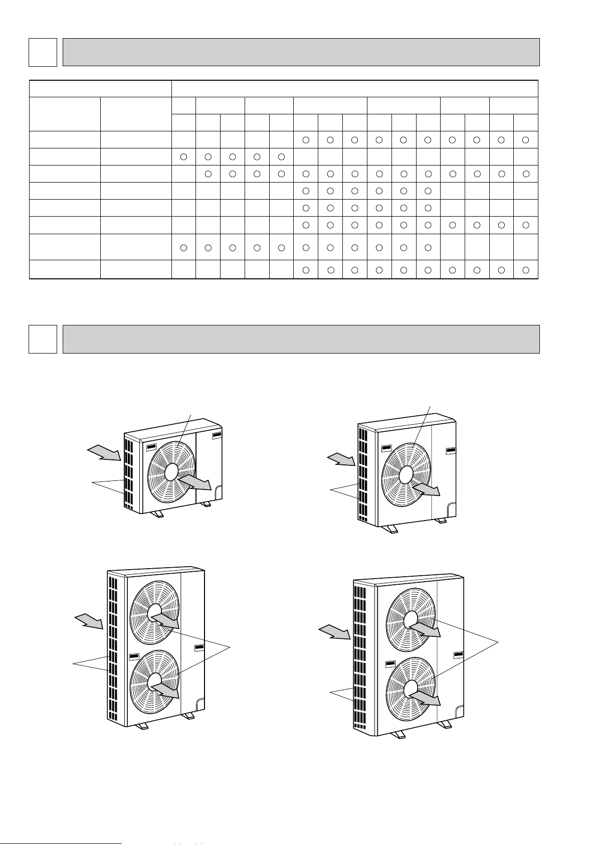
1 COMBINATION OF INDOOR AND OUTDOOR UNITS
Air intake
Air outlet
(Expels warm air during cooling)
Air intake
Air outlet
Air intake
Air outlet
Service
Manual No.
Service
Ref.
OC151
(REVISED EDITION-A)
OC146
OC131
OC143
OC129
PL-GJ(S)B1.UK
PL-KJB.UK
PC-GJ(S)A
1
PE-EJH(S)A1
PS-GJ(S)1
PK-1.6/2FLA3
PK-2.5/3/4FL(S)A2
Indoor unit Outdoor unit
PU-1.6
.UK
PU-2.UK PU-2.5.UK PU-3.UK PU-4.UK PU-5.UK PU-6.UK
VLJSA2
VLJA2
VJA2 NJA1 VJA2
NJA1
VJA2 YJA3
YJSA3 TJSA1
YJSA TJSA YJSA TJSA
NJA1
_____
______
_
_
_
_
________
_
_
_
_
_
_
_
_
_
_
_
_
_
_
_
OC141
(REVISED EDITION-A)
OC155
(REVISED EDITION-A)
PS-GJ(S)A1
PE-EJ(S)A.TH
_
_____
____
OC134
(REVISED EDITION-A)
Air intake
Air outlet
2 PART NAMES AND FUNCTIONS
●Outdoor Unit
wUnit of pressure is based on ISO (International Standardization Organization)
2
PU-1.6VLJA
2.UK
PU-2VJA2.UK
PU-2NJA1.UK
PU-4VLJSA
PU-4YJSA2.UK
PU-4TJSA1.UK
2.UK
[kgf/cm
2
]➝[Mpa] (1MPa=10.2kgf/cm2)
PU-2.5VJA
2.UK
PU-2.5NJA1.UK
PU-3VJA2.UK
PU-3YJA2.UK
PU-3NJA1.UK
PU-5YJSA.UK
PU-5TJSA.UK
PU-6YJSA.UK
PU-6TJSA.UK
Page 3
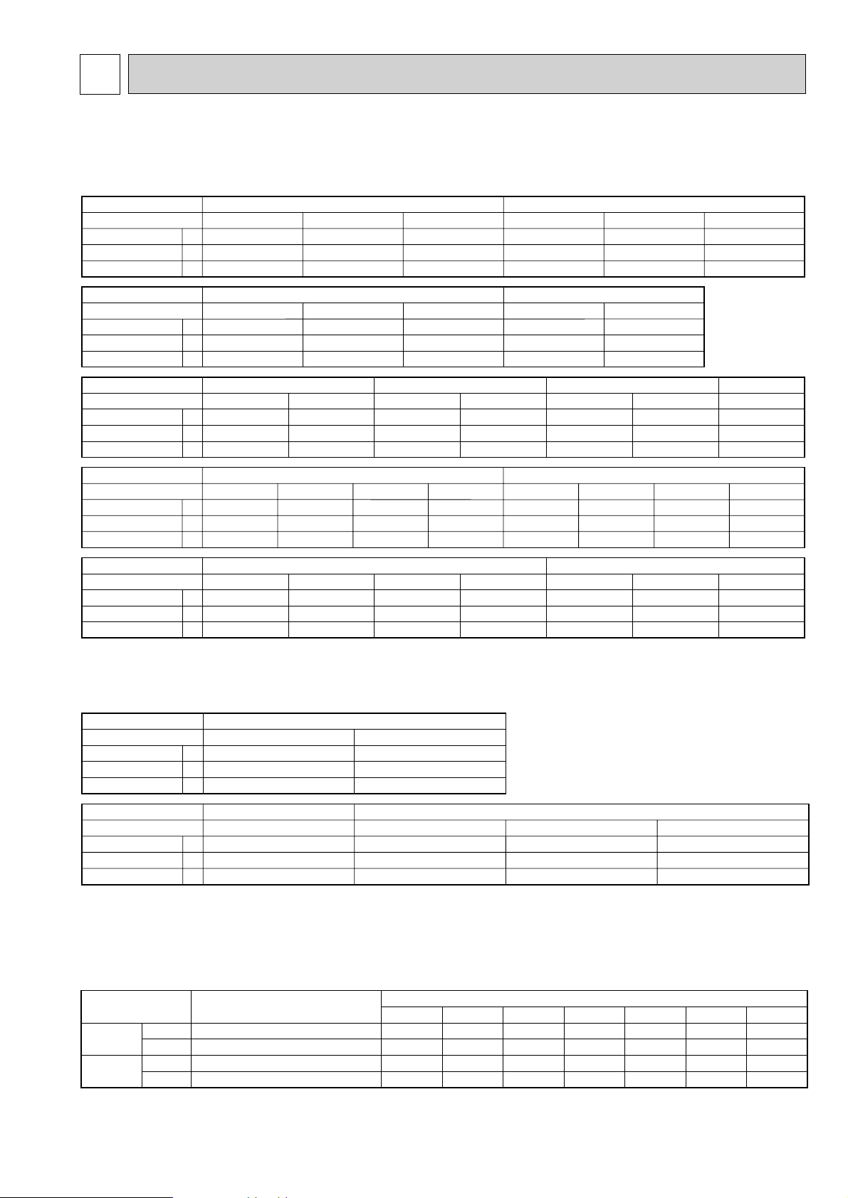
3 DATA
Power supply (1 phase)
Service Ref.
Current
Input
Starting current
A
A
kW
Power supply (1 phase)
Service Ref.
Current
Input
Starting current
A
A
kW
Power supply (3 phase)
Service Ref.
Current
Input
Starting current
A
A
kW
Power supply (3 phase)
Service Ref.
Current
Input
Starting current
A
A
kW
V : 220V 50Hz V : 230V 50Hz
PU-1.6VLJA
2.UK PU-2VJA2.UK PU-2.5VJA2.UK PU-1.6VLJA2.UK PU-2VJA2.UK
PU-1.6VLJA
2.UK
PU-3VJA
2.UK PU-4VLJSA2.UK PU-3VJA2.UK
PU-4VLJSA2.UK
PU-3VJA2.UK
PU-4VLJSA2.UK
PU-3NJA1.UK
PU-2VJA
2.UK PU-2.5VJA2.UK PU-2NJA1.UK
PU-3YJA
2.UK
PU-4YJSA2.UK
PU-5YJSA.UK
PU-3YJA2.UK PU-4YJSA2.UK PU-4TJSA1.UK
PU-6YJSA.UK
PU-2.5NJA1.UK
PU-2.5VJA
2.UK
11.3
2.44
48
6.7
1.42
30
11.4
2.46
45
11.0
2.46
50
6.7
1.47
32
11.0
2.49
47
Power supply (1 phase)
Service Ref.
Current
Input
Starting current
A
A
kW
V : 240V 50Hz N : 220V 60Hz
10.8
2.48
52
6.9
1.52
33
10.7
2.52
49
11.4
2.45
54
13.4
2.91
58
V : 220V 50Hz V : 230V 50Hz V : 240V 50Hz N : 220V 60Hz
15.1
3.18
68
16.9
3.35
79
14.4
3.19
68
16.6
3.44
79
13.9
3.20
68
16.3
3.52
79
17.6
3.44
80
Y : 380/220V 50Hz
5.7
3.18
36
5.7
3.29
38
8.15
4.56
65.5
8.63
5.11
74
PU-3YJA
2.UK
PU-4YJSA2.UK
5.4
3.19
36
5.5
3.33
38
Y : 400/230V 50Hz
PU-5YJSA.UK PU-6YJSA.UK
7.89
4.61
65.5
8.55
5.15
74
Y : 415/240V 50Hz T : 220V 60Hz
5.3
3.20
36
5.5
3.36
38
PU-5YJSA.UK
7.63
4.66
65.5
PU-6YJSA.UK
8.48
5.18
74
12.2
4.27
69
PU-5TJSA.UK
16.83
5.63
135
PU-6TJSA.UK
18.70
6.15
140
Power supply
Service Ref.
Current
Input
Starting current
A
A
kW
PU-2NJA
1.UK
13.6
2.97
54
PU-2.5NJA
1.UK
15.8
3.44
58
N : 220V (1 phase) 60Hz
Power supply
Service Ref.
Current
Input
Starting current
A
A
kW
PU-3NJA
1.UK
20.9
4.09
80
PU-4TJSA
1.UK
14.0
4.97
69
N : 220V (1 phase) 60Hz
PU-5TJSA
.UK
19.61
6.68
135
T : 220V (3 phase) 60Hz
PU-6TJSA
.UK
21.45
7.28
140
Power supply
50Hz
60Hz
1ph.
3ph.
1ph.
3ph.
Service Ref. (indoor unit)
220, 230, 240V
380/220, 400/230, 415/240V
220V
220V
Model name (outdoor unit)/Service Ref.
PU-1.6 PU-2 PU-2.5 PU-3 PU-4
PU-1.6VLJA2.UK
PU-2VJA2.UK PU-2.5VJA2.UK
—
————
—
—
—
—
——
PU-2NJA1.UK PU-2.5NJA1.UK
PU-3VJA
2
.UK
PU-4VLJSA2.UK
PU-3YJA2.UK
PU-3NJA
1
.UK
PU-4YJSA
2
.UK
PU-4TJSA
1
.UK
PU-5
——
PU-5YJSA.UK
PU-5TJSA.UK
PU-6
PU-6YJSA.UK
PU-6TJSA.UK
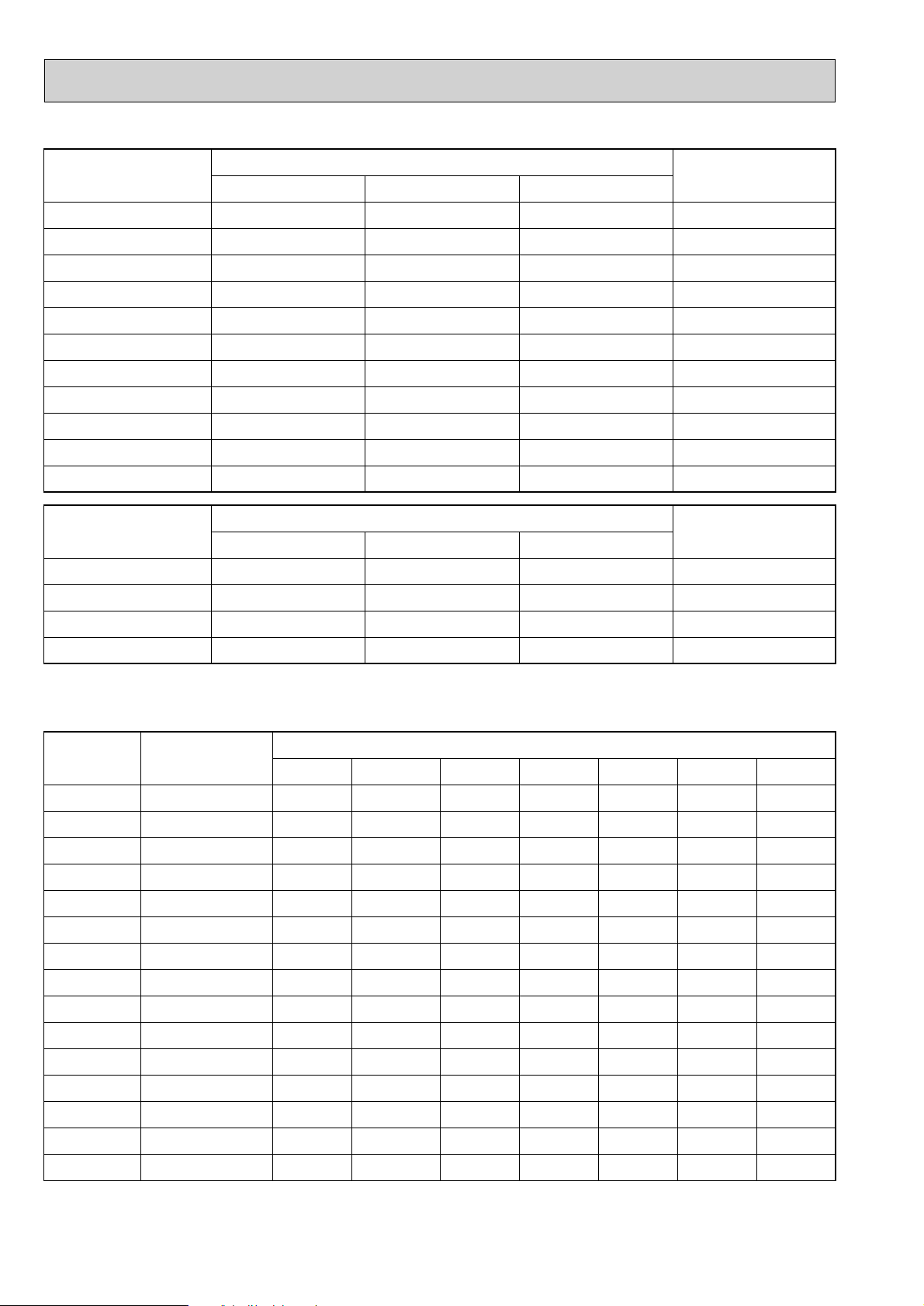
1. ELECTRICAL SPECIFICATIONS
(1) Rating conditions
●JIS B 8616
Indoor : 27˚C(80˚F)D.B.,19˚C(66˚F)W.B.
Outdoor : 35˚C(95˚F)D.B.,24˚C(75˚F)W.B.
●SSA 385,386
2. POWER SUPPLY & MODEL NAMES
Notes : 1.Power supply key N ……1ph,220V,60Hz Y…3ph,380/220,400/230,
Indoor : 29˚C(84˚F)D.B. ,19˚C(66˚F)W.B.
Outdoor : 46˚C(115˚F)D.B.,24˚C(75˚F)W.B.
V(L)…1ph,220,230,240V,50Hz 415/240V,50Hz,4 wires
T
……
3ph,220V,60Hz
3
Page 4
2. COMPRESSOR TECHNICAL DATA
Compressor
RH247VFC
NHJ33NBD
NHJ41VMD
NHJ38NBD
NHJ41VMD
NHJ52VND
NHJ52YDE
NHJ47NAD
NH56VND
NHJ56YDE
NHJ56TKA
Winding resistance("). at 20:
R-C/U-V S-C/V-W W-U
2.00 4.55 –
0.70 1.44 –
0.92 2.44 –
0.70 1.42 –
0.92 2.44 –
0.83 2.03 –
3.68 3.68 –
0.58 1.14 3.68
0.64 1.55 –
3.30 3.30 3.30
0.83 0.83 0.83
Outdoor unit
Service Ref.
PU-1.6VLJA
2.UK
PU-2NJA
1.UK
PU-2VJA
2.UK
PU-2.5NJA
1.UK
PU-2.5VJA
2.UK
PU-3VJA
2.UK
PU-3YJA
2.UK
PU-3NJA
1.UK
PU-4VLJSA
2.UK
PU-4YJSA
2.UK
PU-4TJSA
1.UK
Compressor
Winding resistance("). at 25:
T
1–T2 T2–T3 T3–T1
Outdoor unit
Service Ref.
ZR61KC-TFD
2.53–2.91 2.53–2.91 2.53–2.91
PU-5YJSA.UK
ZR61KC-TF5
0.628–0.722 0.628–0.722 0.628–0.722
PU-5TJSA.UK
ZR72KC-TFD
2.148–2.472 2.148–2.472 2.148–2.472
PU-6YJSA.UK
ZR68KC-TF5
0.517 0.517 0.517
PU-6TJSA.UK
Service Ref.
Outdoor unit
precharged (kg)
(up to 20m)
Refrigerant piping length (one way)
PU-1.6VLJA2.UK
PU-2VJA
2.UK
PU-2NJA
1.UK
PU-2.5VJA
2.UK
PU-2.5NJA
1.UK
PU-3VJA
2.UK
PU-3YJA
2.UK
PU-3NJA
1.UK
PU-4VLJSA
2.UK
PU-4YJSA
2.UK
PU-4TJSA
1.UK
1.3
1.78
1.9
2.4
2.4
3.08
2.88
3.5
3.8
4.6
4.6
20m (66ft) 25m (82ft) 30m (98ft) 35m (115ft) 40m (131ft)
0
0
0
0
0
0
0
0
0
0
0
–
0.06 (0.13)
0.06 (0.13)
0.06 (0.13)
0.06 (0.13)
0.06 (0.13)
0.06 (0.13)
0.06 (0.13)
0.15 (0.33)
0.15 (0.33)
0.15 (0.33)
–––
––
––
––
––
––
––
––
0.45 (0.99) 0.6 (1.32)
0.45 (0.99) 0.6 (1.32)
0.45 (0.99) 0.6 (1.32)
45m (148ft)
–
–
–
–
–
–
–
–
–
–
–
50m (164ft)
–
–
–
–
–
–
–
–
–
–
–
0.12 (0.26)
0.12 (0.26)
0.12 (0.26)
0.12 (0.26)
0.12 (0.26)
0.12 (0.26)
0.12 (0.26)
0.30 (0.66)
0.30 (0.66)
0.30 (0.66)
PU-5YJSA.UK
5.1
0 0.15 (0.33) 0.45 (0.99) 0.6 (1.32) 0.75 (1.65) 0.9 (1.98)0.30 (0.66)
PU-5TJSA.UK
5.1
0 0.15 (0.33) 0.45 (0.99) 0.6 (1.32) 0.75 (1.65) 0.9 (1.98)0.30 (0.66)
PU-6YJSA.UK
5.7
0 0.15 (0.33) 0.45 (0.99) 0.6 (1.32) 0.75 (1.65) 0.9 (1.98)0.30 (0.66)
PU-6TJSA.UK
5.7
0 0.15 (0.33) 0.45 (0.99) 0.6 (1.32) 0.75 (1.65) 0.9 (1.98)0.30 (0.66)
3. ADDITIONAL REFRIGERANT CHARGE (R-22
4
……
kg (lbs))
Page 5
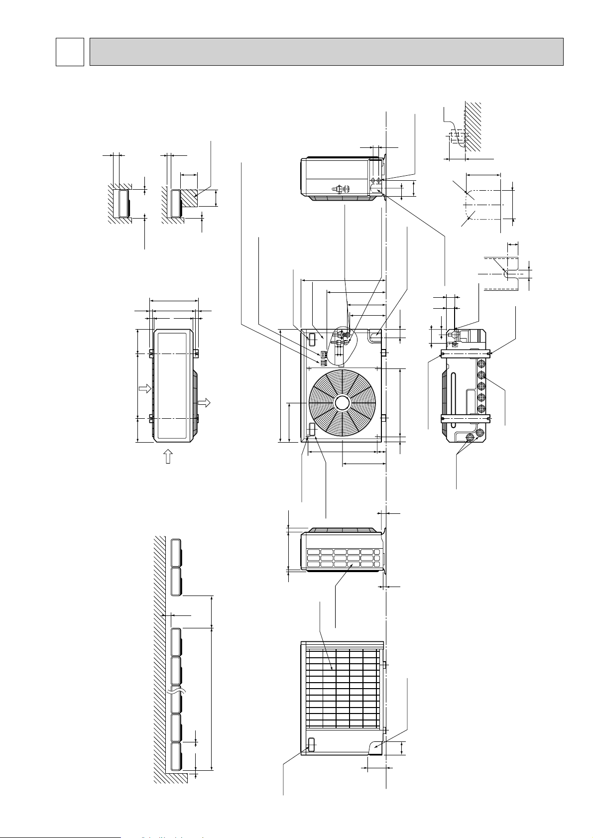
4 OUTLINES AND DIMENSIONS
100 10
1000For 10 units or less
200
Outdoor Unit-necessary surrounding clearance
(Concentrated installation)
The upper side must be open.
Outdoor Unit-necessary surrounding clearance
200
10
10
10
Note:Allow adequate
upper clearance
150
500
500
Service space
Front opening
Handle
for moving
138
95
Rear piping hole
23
33
Rear fresh
air intake
Side air intake
7 24(1)295(11-5/8)
Outlet guide
installation hole
302
Air intake
Air intake
Air outlet
870(34-1/4)
185
(7-9/32)
185
(7-9/32)
500(19-11/16)
330(13)
362(14-1/4)
1715
39.5 27.5
Terminal block for indoor and outdoor unit connection
Terminal block for power line
Handle for moving
77
524
339
282
297
444
650 (25-5/8)
40 60524
Service panel
(Ground terminal)
Refrigerant-pipe flared
connection
[15.88 5/8F
Refrigerant-pipe flared
connection
[9.52 3/8F
Knock out hole
for front piping
(refrigerant,drainage
and wiring)
Knock out hole
for front piping
(refrigerant,drainage
and wiring)
R
20
R20
60
120
4553
25 max.
Knock out holes for
power line 2-[27
Standard bolt length
65
Front right piping holes-
detail figures
80
17
42
45
12
R6
104
33
Bottom
piping hole
2-U-shaped
notched
holes
Drain hole
Drain hole
2-12o23 Oval holes
(standard bolt M10)
Handle for moving
PU-1.6VLJA2.UK/PU-2VJA2.UK/PU-2NJA1.UK
Unit : mm (inch)
5
Page 6
PU-2.5VJA2.UK/PU-2.5NJA1.UK
100 10
1000For 10 units or less
200
Outdoor Unit-necessary surrounding clearance
(Concentrated installation)
The upper side must be open.
Outdoor Unit-necessary surrounding clearance
200
10
10
10
Note:Allow adequate
upper clearance
150
500
500
Service space
Front opening
Handle
for moving
138
95
Rear piping hole
23
33
Rear fresh
air intake
Side air intake
7 24(1)295(11-5/8)
Outlet guide
installation hole
302
Air intake
Air intake
Air outlet
870(34-1/4)
185
(7-9/32)
185
(7-9/32)
500(19-11/16)
330(13)
362(14-1/4)
1715
39.5 27.5
Terminal block for indoor and outdoor unit connection
Terminal block for power line
Handle for moving
179 524
441
337
352
403
553
850(33-7/16)
40 60524
Service panel
(Ground terminal)
Refrigerant-pipe flared
connection [15.88 5/8F
Refrigerant-pipe flared
connection [9.52 3/8F
Knock out hole
for front piping
(refrigerant,drainage
and wiring)
Knock out hole
for front piping
(refrigerant,drainage
and wiring)
R
20
R20
60
120
4553
25 max.
Knock out holes for
power line 2-[27
Standard bolt length
65
Front right piping holes-
detail figures
80
17
42
45
12
R6
104
33
Bottom
piping hole
2-U-shaped
notched
holes
Drain hole
Drain hole
2-12o23 Oval holes
(standard bolt M10)
Handle for moving
PU-3VJA2.UK/PU-3YJA2.UK/PU-3NJA1.UK
Unit : mm (inch)
6
Page 7
PU-4VLJSA2.UK/PU-4YJSA2.UK/PU-4TJSA1.UK
300
Note:Allow adequate
upper clearance
10
150
500
Service space
500
4553
Knock out holes for
power line 2-[27
120
60
R20
Unit : mm (inch)
Standard bolt length
25 max.
80
65
Front opening
10
10
Outdoor Unit-necessary surrounding clearance
Terminal block for
indoor and outdoor
unit connection
Terminal block for power line
362(14-1/4)
1715
185
(7-9/32)
Air intake
500(19-11/16)
185
(7-9/32)
330(13)
39.5 27.5
Air intake
870(34-1/4)
302
Air outlet
(Ground terminal)
Service panel
Handle
for moving
52461
585
Refrigerant-pipe flared
1258(49-1/2)
959
connection [19.05 3/4F
Refrigerant-pipe flared
connection [9.52 3/8F
Knock out hole
for front piping
403
382
83 524
40 60524
345
R20
Knock out hole
for front piping
(refrigerant,
drainage and wiring)
(refrigerant,drainage
and wiring)
57
52
Bottom
39
104
2-12o23 Oval holes
(standard bolt M10)
piping hole
Drain hole
Front right piping holes-
detail figures
17
R6
12
2-U-shaped
notched
holes
Drain hole
Outlet guide
7 24(1)295(11-5/8)
300
1000For 10 units or less
The upper side must be open.
Outdoor Unit-necessary surrounding clearance
(Concentrated installation)
150 10
installation hole
Side air intake
Handle
for moving
Handle for moving
Rear fresh
air intake
33
23
Rear piping hole
95
138
7
Page 8
PU-5YJSA.UK/PU-5TJSA.UK/PU-6YJSA.UK/PU-6TJSA.UK
150 10
1000For 10 units or less
300
Outdoor Unit-Necessary surrounding clearance
(Concentrated installation)
Outdoor Unit-Necessary surrounding clearance
The upper side must be open.
Handle
for moving
138
95
Rear piping hole
23
33
Rear fresh
air intake
Side air intake
7 24(1)345(13-9/16)
Outlet guide
installation hole
352
Air intake
Air intake
Air outlet
970(38-3/16)
185
(7-9/32)
185
(7-9/32)
600(23-5/8)
380(14-31/32)
412(16-1/4)
1715
39.5 27.5
Terminal block for
indoor and outdoor
unit connection
Terminal block for power line
300
10
10
10
Note:Allow adequate
upper clearance
150
500
500
Service space
Handle for moving
52461
585
83 524
345
382
403
959
1258(49-1/2)
90 60524
Service panel
(Ground terminal)
Handle
for moving
Refrigerant-pipe flared
connection [19.05 3/4F
Refrigerant-pipe flared
connection [9.52 3/8F
Knock out hole
for front piping
(refrigerant,drainage
and wiring)
Knock out hole
for right piping
(refrigerant,
drainage and wiring)
R
20
R20
60
120
4553
25 max.
Knock out holes for
power line 2-[27
Standard bolt length
65
Front right piping holes-
detail figures
80
17
52
57
12
R6
104
39
Bottom
piping hole
2-U-shaped
notched
holes
Drain hole
Drain hole
2-12o23 Oval holes
(standard bolt M10)
Front opening
Unit : mm (inch)
8
Page 9
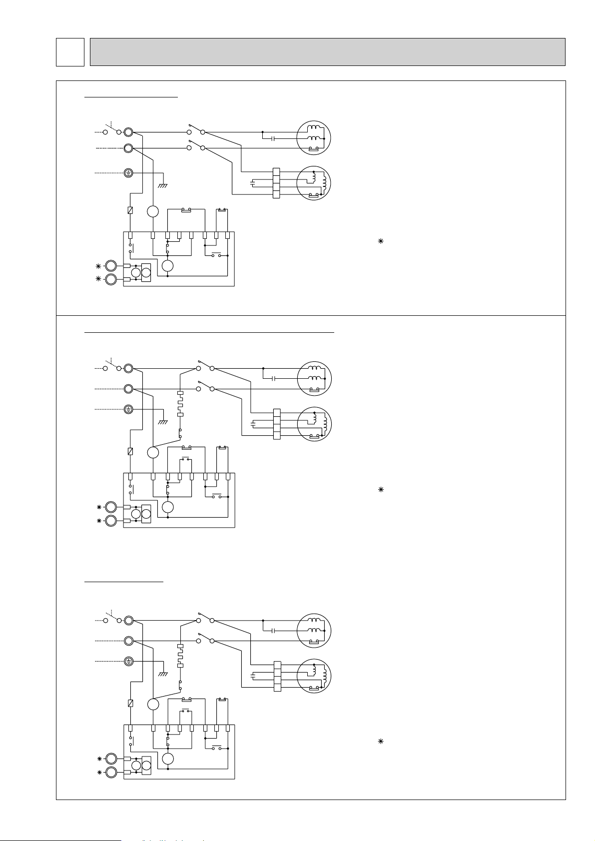
5 WIRING DIAGRAM
PU-1.6VLJA2.UK
L1/1 T1/2
L3/5
63H
GRY
52C
52C
X6
X6
52C
BLU
RED
ORN
WHT
BLU
C
RED
BLU
4
RED
2
ORN
1
WHT
3
BLU
T3/6
WHT
C3
63L
WHT
WHT
GRY
P2P3P3
CP
X17
POWER
SUPPLY
~/N (1PHASE)
220-240V 50Hz
TB3
1
2
RED
WHT
TB1
RED
L
BLU
N
GRN/YLW
RED
BLU
F3
(5A)
A1
52
C
A2
ORN
YLW
1
2
P1BA
X14
X17X14
PU-2VJA2.UK,PU-2.5VJA2.UK,PU-3VJA2.UK
52C
L1/1 T1/2
GRY
L3/5 T3/6
2
HC
1
GRY
22(32)
21(31)
63H
52C
1413
VLT
VLT
52C
P3 P3 P2
RED
WHT
C3
63L
GRY
GRY
WHT
WHT
CP
X17
RED
ORN
WHT
BLK
C
RED
BLUBLU
4
RED
2
ORN
1
WHT
3
POWER
SUPPLY
~/N (1PHASE)
220-240V 50Hz
TB3
TB1
TB1
L
N
RED
F3
(5A)
YLW
ABP1
X14
RED
1
1
X14 X17
2
2
WHT
RED
BLU
GRN/YLW
BLU
EARTH
52C
A1
52
C
A2
ORN
GRY
GRY
GRY
52C
X6
X6
S
C
S
C
R
49F3
R
49F3
49C
49C
C
CP
C3
MC
F3
MC
MF3
TB1
TB3
49C
MF3
49F3
52C
63H
63L
NOTES:1.THE DOTTED LINES SHOW FIELD WIRING.
2. TO INDOOR UNIT TERMINAL BLOCK.
C
CP
C3
MC
F3
HC CRANKCASE HEATER
MC
MF3
TB1
TB3
MF3
49C
49F3
52C
63H
63L
NOTES:1.THE DOTTED LINES SHOW FIELD WIRING.
2. TO INDOOR UNIT TERMINAL BLOCK.
3.THE LETTERS IN THE ( ) INDICATE PU-3VJA
COMPRESSOR RUN CAPACITOR
COMPRESSOR PROTECTOR
FAN MOTOR CAPACITOR
FUSE(5A)
COMPRESSOR
FAN MOTOR
TERMINAL BLOCK (POWER SUPPLY)
TERMINAL BLOCK (CONNECTING WIRES INDOOR/OUTDOOR)
COMPRESSOR INTERNAL THERMOSTAT
FAN MOTOR INTERNAL THERMOSTAT
COMPRESSOR CONTACTOR
HIGH PRESSURE SWITCH
LOW PRESSURE SWITCH
COMPRESSOR RUN CAPACITOR
COMPRESSOR PROTECTOR
FAN MOTOR CAPACITOR
FUSE(5A)
COMPRESSOR
FAN MOTOR
TERMINAL BLOCK (POWER SUPPLY)
TERMINAL BLOCK (CONNECTING WIRES INDOOR/OUTDOOR)
INTERNAL THERMOSTAT FOR MC
INTERNAL THERMOSTAT FOR MF3
COMPRESSOR CONTACTOR
HIGH PRESSURE SWITCH
LOW PRESSURE SWITCH
PU-3NJA1.UK
TB1
POWER
SUPPLY
~/N (1PHASE)
220V 60Hz
F3
(5A)
ABP1
RED
TB3
1
2
WHT
L
N
1
2
YLW
X14
X14 X17
RED
RED
BLU
BLU
A1
52
C
A2
ORN
GRN/YLW
GRY
GRY
X6
52C
52C
X6
GRY
GRY
32
31
63H
52C
VLT
52C
52C
L1/1 T1/2
L3/5 T3/6
2
HC
1
1413
WHT
GRY
VLT
P3 P3 P2
X17
63L
WHT
RED
WHT
BLK
R
C
RED
S
C
49C
BLU
BLU
4
RED
RED
ORN
WHT
2
ORN
1
WHT
3
49F3
C3
CP
C
CP
C3
MC
F3
HC CRANKCASE HEATER
MC
MF3
TB1
TB3
MF3
49C
49F3
52C
63H
63L
NOTES:1.THE DOTTED LINES SHOW FIELD WIRING.
2. TO INDOOR UNIT TERMINAL BLOCK.
COMPRESSOR RUN CAPACITOR FOR
COMPRESSOR PROTECTOR
FAN MOTOR CAPACITOR
FUSE(5A)
COMPRESSOR
FAN MOTOR
TERMINAL BLOCK (POWER SUPPLY)
TERMINAL BLOCK (CONNECTING WIRES INDOOR/OUTDOOR)
INTERNAL THERMOSTAT FOR MC
INTERNAL THERMOSTAT FOR MF3
COMPRESSOR CONTACTOR
HIGH PRESSURE SWITCH
LOW PRESSURE SWITCH
9
Page 10
PU-2NJA1.UK,PU-2.5NJA1.UK
C
CP
C3,4
F3
MC
MF3.4
TB1
TB3
49C
49F3.4
52C
26C
RUN CAPACITOR FOR MC
COMPRESSOR PROTECTOR
FAN MOTOR CAPACITOR
FUSE(5A)
HC CRANKCASE HEATER
COMPRESSOR
FAN MOTOR
TERMINAL BLOCK (POWER SUPPLY)
TERMINAL BLOCK (CONNECTING WIRES INDOOR/OUTDOOR)
INTERNAL THERMOSTAT FOR MC
INTERNAL THERMOSTAT FOR MF3,4
COMPRESSOR CONTACTOR
THERMAL SWITCH (DIS. CHARGE)
63H
63L
HIGH PRESSURE SWITCH
LOW PRESSURE SWITCH
NOTES:1.THE DOTTED LINES SHOW FIELD WIRING.
2. TO INDOOR UNIT TERMINAL BLOCK.
3.POWER SUPPLY ~ (1PHASE) 220–240V,50Hz
26C
L
N
220-240V 50Hz
~/N (1PHASE)
SUPPLY
POWER
GRN/YLW
RED
C
C
S
BLK
WHT
RED
49C
BLU
WHT
GRY
GRY
GRY
ORN
BLU
T3/6
L3/5
1
1
RED
(5A)
F3
BLU
RED
52C
32
31
A1
A2
1413
HC
63H
63L
52C
WHT
VLT
WHT
GRY
VLT
GRY
YLW
2
2
T1/2
L1/1
52C
C
52
TB1
R
MF4
49F4
WHT
ORN
RED
BLU
WHT
YLW
BRN
BLU
MC
MF3
49F3
C4
C3
WHT
ORN
RED
BLU
BLU
RED
ORN
WHT
3
1
2
4
3
1
2
4
CP
X17
X6
X14
52C
P2P3P3
52C
P1BA
WHT
RED
TB3
X6
2
1
1
2
X17X14
GRN/YLW
TB1
RED
BLU
A1
A2
63L
63H
1413
52C
VLT
VLT
GRY
GRY
GRY
GRY
X14 X17
2
1
1
2
X6
TB3
RED
WHT
ABP1
52C
P3 P3 P2
52C
X14
X6
X17
CP
4
2
1
3
WHT
ORN
RED
BLUBLU
RED
ORN
WHT
C3
49F3
MF3
MC
R
52
C
POWER
SUPPLY
52C
L1/1 T1/2
YLW
WHT
WHT
F3
(5A)
RED
L3/5 T3/6
BLU
ORN
49C
RED
WHT
BLK
S
C
C
RED
~/N (1PHASE)
220V 60Hz
L
N
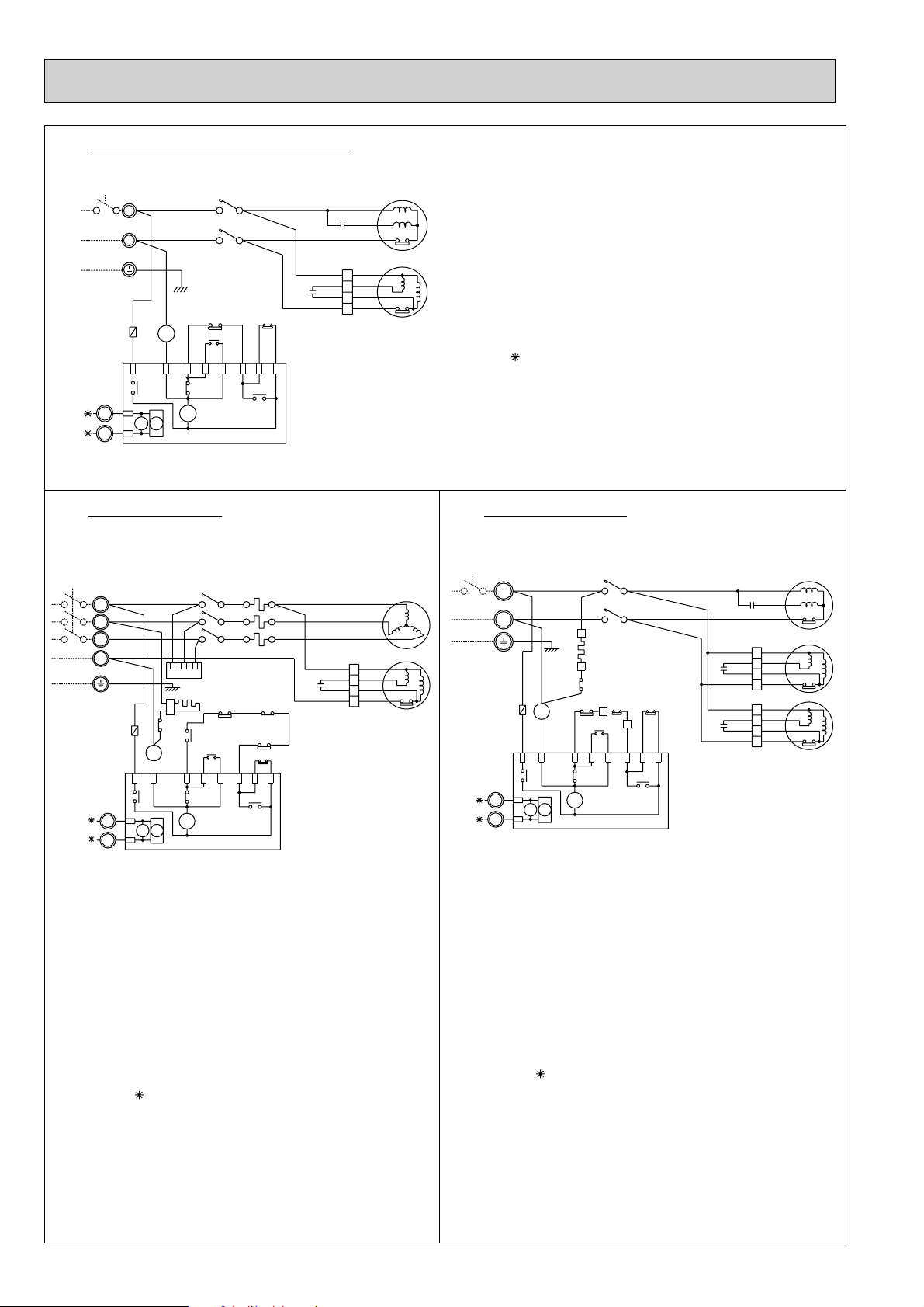
PU-3YJA2.UK
POWER SUPPLY
3N~ (3PHASE 4WIRES)
380/220-415/240V 50Hz
L1
L2
L3
N
TB3
CP
C3
F3
HC CRANKCASE HEATER
10
MC
MF3
TB1
TB3
26C
47 ANTI-PHASE PROTECTOR
49F3
51C THERMAL RELAY
52C
63H
63L
NOTES:1.THE DOTTED LINES SHOW FIELD WIRING.
2. TO INDOOR UNIT TERMINAL BLOCK.
RED
WHT
BLK
GRY
GRN/YLW
BLU
RED
22
F3
(5A)
21
A1
52
C
A2
YLW
RED
1
2
X14
1
X17X14
2
WHT
COMPRESSOR PROTECTOR
FAN MOTOR CAPACITOR
FUSE(5A)
COMPRESSOR
FAN MOTOR
TERMINAL BLOCK (POWER SUPPLY)
TERMINAL BLOCK (CONNECTING WIRES INDOOR/OUTDOOR)
THERMAL SWITCH
INTERNAL THERMOSTAT FOR MF3
COMPRESSOR CONTACTOR
HIGH PRESSURE SWITCH
LOW PRESSURE SWITCH
52C
GRY
ORN
RED
1
2
RTS
WHT
C
A
P1BA
X6
52C 51C
L1/1
L2/3
L3/5
BLU
47
HC
YLW
47
52C
BLU
VLT
52C
52C
X6
26C
1413
VLT
YLW
GRY
C
CP
C3
F3
MC
MF3
TB1
TB3
49C
49F3
52C
63H
63L
NOTES:1.THE DOTTED LINES SHOW FIELD WIRING.
2. TO INDOOR UNIT TERMINAL BLOCK.
RUN CAPACITOR FOR MC
COMPRESSOR PROTECTOR
FAN MOTOR CAPACITOR
FUSE(5A)
COMPRESSOR
FAN MOTOR
TERMINAL BLOCK (POWER SUPPLY)
TERMINAL BLOCK (CONNECTING WIRES INDOOR/OUTDOOR)
INTERNAL THERMOSTAT FOR MC
INTERNAL THERMOSTAT FOR MF3
COMPRESSOR CONTACTOR
HIGH PRESSURE SWITCH
LOW PRESSURE SWITCH
PU-4VLJSA2.UK
GRY
RED
WHT
BLK
WHT BLU
4
RED
RED
2
C3
ORN
ORN
1
BLU
WHT
3
T1/2
T2/4
T3/6
51C
9596
63H
63L
WHT
WHT
P2P3P3
X17
CP
49F3
MC
U
V
W
MF3
Page 11
PU-4TJSA1.UK
POWER
SUPPLY
3~ (3PHASE)
220V 60Hz
TB3
1
2
TB1
L1
L2
L3
RED
WHT
(5A)
F3
RED
GRN/
YLW
RED
1
2
52C 51C
BLU
C3
C4
RED
WHT
BLK
BLU BLU
4
RED
RED
2
ORN
ORN
1
WHT
WHT
3
BLU
BLU
4
RED
BRN
2
ORN
YLW
1
WHT
WHT
3
V
W
49F3
49F4
L1/1
WHT
L2/3
BLK
L3/5
GRY
RED
WHT
BLU
47
RTS
HC
1
2
GRY
32
52C
31
A1
52
C
A2
ORN
YLW
X14
P1BA
X6
X17X14
63H
52C
1413
GRY
X6
52C
VLT
VLT
52C
BRN
X17
63L
WHT
T1/2
T2/4
T3/6
WHT
51C
YLWGRY
9695
26C
47
AC
YLW
WHT
P2P3P3
CP
MC
U
MF3
MF4
CP
C3,4
F3
HC CRANKCASE HEATER
MC
MF3,4
TB1
TB3
26C
47 ANTI-PHASE PROTECTOR
49F3,4
51C THERMAL RELAY
52C
63H
63L
NOTES:1.THE DOTTED LINES SHOW FIELD WIRING.
2. TO INDOOR UNIT TERMINAL BLOCK.
COMPRESSOR PROTECTOR
FAN MOTOR CAPACITOR
FUSE(5A)
COMPRESSOR
FAN MOTOR
TERMINAL BLOCK (POWER SUPPLY)
TERMINAL BLOCK (CONNECTING WIRES INDOOR/OUTDOOR)
THERMAL SWITCH
INTERNAL THERMOSTAT
COMPRESSOR CONTACTOR
HIGH PRESSURE SWITCH
LOW PRESSURE SWITCH
PU-4YJSA2.UK
POWER SUPPLY
3N~ (3PHASE 4WIRES)
380/220-415/240V 50Hz
RED
L1
L2
L3
N
RED
F3
(5A)
YLW
RED
TB3
1
2
WHT
1
2
X14
WHT
BLK
A1
52
A2
BLU
C
X17X14
22
21
GRY
52C
GRY
RED
RTS
GRN/YLW
1
2
ORN
P1BA
52C 51C
L1/1
L2/3
L3/5
WHT
BLU
47
HC
52C
GRY
VLT
52C
52C
X6
X6
1413
63H
MC
U
V
W
4
RED
2
ORN
1
WHT
3
49F3
BLU
4
RED
2
ORN
1
WHT
3
49F4
MF3
MF4
CP
C3,4
F3
HC CRANKCASE HEATER
MC
MF3,4
TB1
TB3
26C
47 ANTI-PHASE PROTECTOR
49F3,4
51C THERMAL RELAY
52C
63H
63L
NOTES:1.THE DOTTED LINES SHOW FIELD WIRING.
2. TO INDOOR UNIT TERMINAL BLOCK.
3.POWER SUPPRY 3N~ (3PHASE 4WIRES) 380/220-415/240V 50Hz
COMPRESSOR PROTECTOR
FAN MOTOR CAPACITOR
FUSE(5A)
COMPRESSOR
FAN MOTOR
TERMINAL BLOCK (POWER SUPPLY)
TERMINAL BLOCK (CONNECTING WIRES INDOOR/OUTDOOR)
THERMAL SWITCH
INTERNAL THERMOSTAT
COMPRESSOR CONTACTOR
HIGH PRESSURE SWITCH
LOW PRESSURE SWITCH
WHT
C3
C4
RED
WHT
BLK
BLU BLU
RED
ORN
WHT
BLU
BRN
YLW
WHT
T1/2
T2/4
T3/6
BLU
51C
YLWGRY
9695
26C
47
AC
YLW
63L
VLT
BRN
X17
WHT
WHT
P2P3P3
CP
11
Page 12

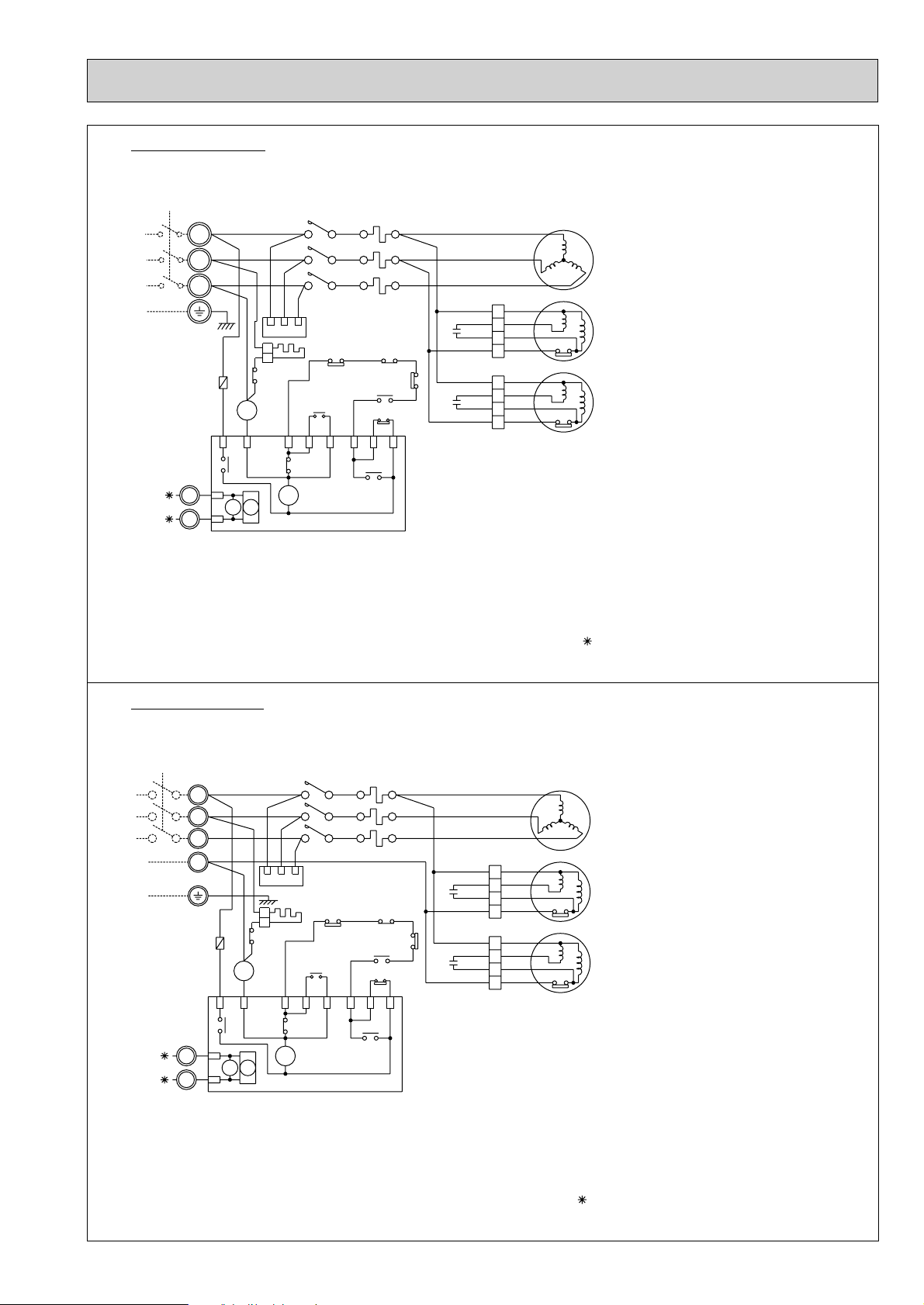
PU-5TJSA.UK, PU-6TJSA.UK
CIRCUID
BREAKER
WHT
T2/4
49C
49C
49C
GRY
26C
T1/2
GRN/YLW
3~ (3PHASE)
220V 60Hz
POWER SUPPLY
L1
L2
L3
BLK
WHT
RED
(5A)
F3
WHT
RED
A1
A2
BLK
AC
1413
63H
47
52C
GRY
RED
WHT
GRY
RED
BLK
YLW
47
RTS
RED
WHT
BLK
L3/5
L2/3
L1/1
52C
C
52
T3/6
BLU
T3
T2
T1
BLK
WHT
RED
MF4
49F4
WHT
ORN
RED
BLU
WHT
YLW
BRN
BLU
MC
MF3
49F3
C4
C3
WHT
ORN
RED
BLU BLU
RED
ORN
WHT
3
1
2
4
3
1
2
4
CP
X17
X6
X14
52C
P2P3P3
52C
P1BA
WHT
RED
TB3
X6
2
1
*
*
1
2
X17X14
CP
C3,4
F3
MC
MF3,4
TB1
TB3
26C
47
49F3,4
49C
52C
63H
COMPRESSOR PROTECTOR
FAN MOTOR CAPACITOR
FUSE(5A)
COMPRESSOR
FAN MOTOR
POWER SUPPLY TERMINAL BLOCK
INDOOR/OUTDOOR CONNECTING LINE TERMINAL BLOCK
THERMAL SWITCH
PHASE PROTECTOR
FAN MOTOR INTERNAL THERMOSTAT
INTERNAL THERMOSTAT FOR MC
COMPRESSOR CONTACTOR
HIGH PRESSURE SWITCH
WHT
CIRCUID
BREAKER
BLU
49C
49C
49C
GRY
26C
T1/2
GRN/YLW
N
3N~ (3PHASE 4WIRES)
380/220-415/240V 50Hz
POWER SUPPLY
L1
L2
L3
BLK
WHT
RED
(5A)
F3
BLU
RED
A2
BLK
AC
1413
63H
47
52C
GRY
RED
WHT
GRY
RED
BLK
YLW
47
RTS
RED
WHT
BLK
L3/5
L2/3
L1/1
52C
C
52
T3/6
T2/4
T3
T2
T1
BLK
WHT
RED
MF4
49F4
WHT
ORN
RED
BLU
WHT
YLW
BRN
BLU
MC
MF3
49F3
C4
C3
WHT
ORN
RED
BLU BLU
RED
ORN
WHT
3
1
2
4
3
1
2
4
CP
X17
X6
X14
52C P2P3P352CP1BA
WHT
RED
TB3
X6
2
1
*
*
1
2
X17X14
CP
C3,4
F3
MC
MF3,4
TB1
TB3
26C
47
49F3,4
49C
52C
63H
COMPRESSOR PROTECTOR
FAN MOTOR CAPACITOR
FUSE(5A)
COMPRESSOR
FAN MOTOR
POWER SUPPLY TERMINAL BLOCK
INDOOR/OUTDOOR CONNECTING LINE TERMINAL BLOCK
THERMAL SWITCH
PHASE PROTECTOR
FAN MOTOR INTERNAL THERMOSTAT
INTERNAL THERMOSTAT FOR MC
COMPRESSOR CONTACTOR
HIGH PRESSURE SWITCH
NOTES:1.THE DOTTED LINES SHOW FIELD WIRING.
2. TO INDOOR UNIT TERMINAL BLOCK.
A1
PU-5YJSA.UK, PU-6YJSA.UK
12
Page 13

6 REFRIGERANT SYSTEM DIAGRAM
Low pressure
switch
Charge
plug
Ball
valve
Ø15.88
(5/8)
Ball valve
(with service port)
Accumulator
Ø9.52
(3/8)
PU-1.6 (O.D.3.2oI.D.1.8-R 900)
PU-2 (O.D.4.0oI.D.2.0-R 430)
Check plug
Compressor
Capillary tube
O.D.3.2oI.D.1.2-R1000
Capillary tube
for injection
(Only PU-2NJ1.UK
PU-2VJA
2.UK)
Strainer
Outdoor heat
exchanger
High pressure
switch
flow of refrigerant
Charge
plug
Ball
valve
Ball valve
(with service port)
Accumulator
Ø9.52
(3/8)
Compressor
Capillary tube for
injection
O.D.
3.2o
I.D.
1.2-R1000
Strainer
Outdoor heat
exchanger
Check
plug
flow of refrigerant
Low pressure
switch
High pressure
switch
Ø15.88
(5/8)
Capillary
tube
(O.D.3.2oI.D.1.6
-R760)o2pcs
Charge
plug
Ball
valve
Ball valve
(with service port)
Accumulator
Ø9.52
(3/8)
Compressor
Capillary tube for
injection
Strainer
Outdoor heat
exchanger
Check
plug
flow of refrigerant
Low pressure
switch
High pressure
switch
Capillary
tube
PU-3NJA,3VJA
PU-3YJA
(O.D.3.2oI.D.1.8-R 800)o2pcs
PU-4VLJSA
PU-4YJSA
PU-4TJSA
(O.D.3.2oI.D.2.0-R 840)o2pcs
PU-3JA
Ø15.88
(5/8)
PU-4JSA
Ø19.05
(3/4)
PU-3VJA
PU-3YJA
PU-3NJA
PU-4YJSA
PU-4TJSA
(O.D.3.2oI.D.2.0-R520)
(O.D.3.2oI.D.1.4-R800)
(O.D.3.2oI.D.1.6-R500)
(O.D.3.2oI.D.1.2-R500)
Only
}
Strainer
Outdoor
heat
exchanger
Ball
valve
Ball valve
(with service port)
High pressure
switch
Compressor
Accumulator
DPR
Capillary tube
PU-5Y·TJSA (O.D. 4.0 oI.D. 2.4 –R400)
PU-6Y·TJSA (O.D. 4.0 oI.D. 2.4 –R200)
Capillary tube
PU-5Y·TJSA
(O.D. 4.0 oI.D. 2.4 –R840)o2pcs
PU-6YJSA
(O.D. 4.0 oI.D. 2.4 –R1200)o2pcs
PU-6TJSA
(O.D. 4.0 oI.D. 2.4 –R740)o2pcs
[9.52
(3/8)
[19.05
(3/4)
Check plug
Charge
plug
: flow of refrigerant
PU-1.6VLJA2.UK
PU-2VJA2.UK,PU-2NJA1.UK
PU-2.5VJA2.UK
PU-2.5NJA1.UK
PU-3VJA2.UK,PU-3YJA2.UK,PU-3NJA1.UK
PU-4VLJSA2.UK,PU-4YJSA2.UK,PU-4TJSA1.UK
PU-5TJSA.UK, PU-5YJSA.UK
PU-6TJSA.UK, PU-6YJSA.UK
13
Page 14

7 DISASSEMBLY PROCEDURE
Model : PU-4JSA.UK type
OPERATING PROCEDURE PHOTOS
1. Removing the electrical parts
(1)
Remove the 3 screws at the front and the 2 screws at
the rear of the top panel.
(2) Remove the top panel.
(3)
Remove the screw from the panel cover. Unhook the
catches from the side panel and pull the panel cover
toward you to remove.
(4)
Remove the screw from the service panel. Pull down the
service panel to unhook the caches. Pull the service
panel toward you to remove.
Photo 1
Photo 2
Screws
Panel cover
Compressor protector
Run capacitor
52C relay
2. Removing the fan motor
(1)
Remove the 3 screws and the front panel.
Open the panel to a 45-degree angle and lift it to
remove. The panel is hooked by 3 catches on the left
side.
(2)
Remove the propeller nuts and the propellers.
(3)
Remove the 3 screws each and the fan motors.
Disconnect the lead connectors.
Screws
Photo 3
Propeller
nut
Motor support
Terminal block
Separator support place
High-pressure
switch
Valve bed
14
Propeller
Crankcase heater
Page 15

OPERATING PROCEDURE PHOTOS
3. Removing the heat exchanger and the compressor
NOTE :
When removing the panels, move them up and down
to unhook catches.
(1)
Remove the rear panel set screws: 2 screws at the
front, 1 screw on the side, and 3 screws at the rear.
(2) Remove the valve bed.
(3) Open the rear panel rearward to remove.
(4)
Remove the 4 screws of the right side panel and
remove it.
(5)
Remove the 3 screws of the rear guard and remove it.
(6)
Remove the 4 screws of the separator support plate
and remove it.
(7)
Remove the 2 screws of the motor support and
remove it.
(8)
Remove the 5 screws of the valve bed. Lift the valve
bed to unhook the catches on both sides.
(9)
Remove the electrical parts box.
(10) Disconnect the connectors of the high-pressure
switch, crankcase heater, shell thermo, and fan motor.
(11)
Remove the 2 screws of the separator and remove it.
(12)
Remove the 2 screws of the heat exchanger and
remove it.
(13) Detach the welded points of the pipe.
(14) Remove the 3 nuts of the compressor and remove it.
(15) Detach the welded points of the suction pipe and
discharge pipe.
Photo 4
Photo 5
Screws
Screws
Heat exchanger
SUCTION
Muffler
Photo 6
Accumulator
Charge plug
Ball valve
Compressor
15
Page 16

8 PARTS LIST
1
2
3
4
5
6
7
8
9
10
11
12
13
14
R01 A00 641
—
S70 020 668
S70 001 675
R01 A00 655
S70 020 661
R01 A00 662
—
—
R01 A00 682
R01 A00 658
R01 A00 698
S70 021 130
S70 020 686
S70 001 686
Part No. Part Name Specification
No.
Q,ty/set
VLJA.UK
VLJA1.UK
PU-1.6
VJA.UK
VJA1.UK
PU-2
Wining
Diagram
Symbol
Recom-
mended
Q,ty
Price
Unit
Amount
TOP PANEL
F. ST SCREW
FRONT PANEL
FAN GUARD
PANEL HANDLE
SERVICE PANEL
SIDE PANEL
LABEL (MITSUBISHI)
LABEL (BRAND)
REAR PANEL
PANEL COVER
REAR GUARD
MOTOR SUPPORT
BASE
BASE
1
13
1
1
3
1
1
1
1
1
1
1
1
1
1
13
1
1
3
1
1
1
1
1
1
1
1
1
(Z004M203H10)
(DG79R130H01)
(BC79G510H02)
(5O10)
Remarks
(Deawing No)
STRUCTURAL PARTS
PU-1.6VLJA.UK, PU-2VJA.UK
PU-1.6VLJA1.UK, PU-2VJA1.UK
112
8105
2
7
5
3
4
16
1413 9611
Page 17

STRUCTURAL PARTS
PU-1.6VLJA2.UK
PU-2VJA2.UK
PU- 2NJA1.UK
112
8105
2
7
5
3
4
1
R01 A00 641
2
3
R01 A00 668
4
R01 A00 675
5
R01 A00 655
W
6
R01 A00 661
7
R01 A00 662
8
9
10
R01 A00 682
11
R01 A00 658
12
R01 A00 698
S70 021 130
13
S70 030 130
R01 A04 686
14
R01 A00 686
Part No. Part Name
TOP PANEL
—
—
—
F. ST SCREW
FRONT PANEL
FAN GUARD
PANEL HANDLE
SERVICE PANEL
SIDE PANEL
LABEL (MITSUBISHI)
LABEL(BRAND)
REAR PANEL
PANEL COVER
REAR GUARD
MOTOR SUPPORT
MOTOR SUPPORT
BASE
BASE
1413 9611
Q,ty/set
SpecificationNo.
(5o10)
PU-1.6
VLJA2
.UK
1
13
1
1
3
1
1
1
1
1
1
1
1
1
VJA2
.UK
1
13
1
1
3
1
1
1
1
1
1
1
1
1
PU-2
NJA1
.UK
1
13
1
1
3
1
1
1
1
1
1
1
1
1
Remarks
(Drawing No.)
(Z004M203H10)
(DG79R130H01)
(BC79G510H02)
Wiring
Diagram
Symbol
Recommended
Q,ty
Unit
Price
Amount
17
Page 18

STRUCTURAL PARTS
PU-2.5VJA.UK, PU-3VJA.UK, PU-3YJA.UK
PU-2.5VJA1.UK, PU-3VJA1.UK, PU-3YJA1.UK
112
8105
2
7
3
5
4
No.
1
R01 A00 641
2
3
S70 001 668
4
S70 001 675
5
R01 A00 655
6
S70 001 661
7
R01 A08 662
8
9
10
R01 A08 682
11
R01 A00 658
12
R01 A08 698
W
13
S70 030 130
14
S70 001 686
18
Part No. Part Name
TOP PANEL
—
—
—
F. ST SCREW
FRONT PANEL
FAN GUARD
PANEL HANDLE
SERVICE PANEL
SIDE PANEL
LABEL (MITSUBISHI)
LABEL (BRAND)
REAR PANEL
PANEL COVER
REAR GUARD
MOTOR SUPPORT
BASE
14 13 9 6 11
Q,ty/set
Specification
(5O10)
PU-2.5 PU-3
VJA.UK
VJA1.UK
1
13
1
1
3
1
1
1
1
1
1
1
1
1
VJA.UK
VJA1.UK
1
13
1
1
3
1
1
1
1
1
1
1
1
1
YJA.UK
YJA1.UK
1
13
1
1
3
1
1
1
1
1
1
1
1
1
Remarks
(Deawing No)
(Z004M203H10)
(DG79R130H01)
(BC79G510H02)
Wining
Diagram
Symbol
Recommended
Q,ty
Unit
Price
Amount
Page 19

STRUCTURAL PARTS
PU-2.5VJA2.UK
PU-2.5NJA1.UK
PU-3VJA2.UK
PU-3YJA2.UK
PU-3NJA
1.UK
2
7
3
5
4
112
8105
1
R01 A00 641
2
3
R01 A08 668
4
R01 A00 675
W
5
R01 A00 655
6
R01 A08 661
7
R01 A08 662
W
8
9
10
R01 A08 682
11
R01 A00 658
12
R01 A08 698
13
S70 030 130
W
14
R01 A04 686
W
Part No. Part Name
TOP PANEL
—
—
—
F. ST SCREW
FRONT PANEL
FAN GUARD
PANEL HANDLE
SERVICE PANEL
SIDE PANEL
LABEL (MITSUBISHI)
LABEL(BRAND)
REAR PANEL
PANEL COVER
REAR GUARD
MOTOR SUPPORT
BASE
14 13 9 6 11
Q,ty/set
SpecificationNo.
(5
o10)
PU-2.5 PU-3
VJA2.UK
NJA
1.UK
1
13
1
1
3
1
1
1
1
1
1
1
11
11
VJA
YJA
2.UK
2.UK
1
13
1
1
3
1
1
1
1
1
1
1
NJA
13
1.UK
1
1
1
3
1
1
1
1
1
1
1
1
1
Remarks
(Drawing No.)
(Z004M207H10)
(DG79R130H01)
(BC79G510H02)
Wiring
Diagram
Symbol
Recom-
mended
Q,ty
Unit
Price
Amount
19
Page 20

STRUCTURAL PARTS
PU-4VLJSA.UK, 4YJSA.UK
PU-4VLJSA1.UK, 4YJSA1.UK
112
810
2
7
3
5
4
No.
10
11
12
13
14
Part No. Part Name Specification
1
R01 A00 641
2
3
S70 004 668
4
S70 001 675
5
T7W 510 241
6
S70 004 661
7
T7W 515 716
8
9
R01 A11 682
R01 A00 658
R01 A11 698
S70 004 130
S70 001 686
—
—
—
14 13 9 5 11
TOP PANEL
F. ST SCREW
FRONT PANEL
FAN GUARD
PANEL HANDLE
SERVICE PANEL
SIDE PANEL
LABEL (MITSUBISHI)
LABEL (BRAND)
REAR PANEL
PANEL COVER
REAR GUARD
MOTOR SUPPORT
BASE
(5O10)
Q,ty/set
PU-4
VLJSA.UK
VLJSA1.UK
1
13
1
2
3
1
1
2
1
1
1
1
1
1
YJSA.UK
YJSA1.UK
1
13
1
2
3
1
1
2
1
1
1
1
1
1
6
Remarks
(Deawing No)
(Z004M203H10)
(DG79R130H01)
(BG79G510H02)
Wining
Diagram
Symbol
Recom-
mended
Q,ty
Unit
Price
Amount
20
Page 21

STRUCTURAL PARTS
R01 A00 641
R01 A11 668
R01 A00 675
R01 A00 655
R01 A11 661
R01 A11 662
R01 A11 682
R01 A00 658
R01 A11 698
S70 004 130
R01 A10 686
1
2
3
4
5
6
7
8
9
10
11
12
13
Part No. Part Name
SpecificationNo.
Q,ty/set
Wiring
Diagram
Symbol
Recommended
Q,ty
Price
Unit
Amount
TOP PANEL
F. ST SCREW
FRONT PANEL
FAN GUARD
PANEL HANDLE
SERVICE PANEL
SIDE PANEL
LABEL (MITSUBISHI)
LABEL(BRAND)
REAR PANEL
PANEL COVER
REAR GUARD
MOTOR SUPPORT
1
13
1
2
3
1
1
1
1
1
1
1
1
Remarks
(Drawing No.)
(DG79R130H01)
(BC79G510H02)
(Z004M203H10)
(5o10)
—
—
—
14
VLJSA
2.UK
YJSA2.UK
TJSA1.UK
PU-4
BASE
1
W
PU-4VLJSA2.UK
PU-4YJSA2.UK
PU-4TJSA1.UK
2
7
4
3
5
11213
8
10
4
14 6
5
9
11
21
Page 22

STRUCTURAL PARTS
1
2
3
4
5
6
7
8
9
10
11
12
13
14
Part No. Part Name
SpecificationNo.
Q,ty/set
Wiring
Diagram
Symbol
Recommended
Q,ty
Price
Unit
Amount
TOP PANEL
F. ST SCREW
FRONT PANEL
FAN GUARD
PANEL HANDLE
SERVICE PANEL
SIDE PANEL
LABEL (MITSUBISHI)
LABEL(BRAND)
REAR PANEL
PANEL COVER
REAR GUARD
MOTOR SUPPORT
BASE
1
13
1
2
3
1
1
1
1
1
1
1
1
Remarks
(Drawing No.)
(DG79R130H01)
(BC79G510H02)
(Z004M203H10)
(5o10)
TJSA.UK
YJSA.UK
TJSA.UK
YJSA.UK
PU-5 PU-6
1
13
1
2
3
1
1
1
1
1
1
1
1
1
1
R01 A14 641
S70 010 668
S70 001 675
R01 A00 655
R01 A14 661
R01 A14 662
R01 A14 682
R01 A14 658
R01 A14 698
S70 050 130
S70 010 686
W
PU-5YJSA.UK, PU-5TJSA.UK
PU-6YJSA.UK, PU-6TJSA.UK
3
7
2
13
1
12
8
6
10
4
5
11
22
514
9
Page 23

FUNCTIONAL PARTS
1
2
3
4
5
6
7
8
9
10
11
12
13
14
15
16
17
18
19
Part No. Part Name Specification
No.
Q,ty/set
PU-1.6
VLJA
.UK
VLJA
1
.UK
Wining
Diagram
Symbol
Recom-
mended
Q,ty
Price
Unit
Amount
OUTDOOR FAN MOTOR
PROPELLER FAN
COMPRESSOR PROTECTOR
COMPRESSOR PROTECTOR
FUSE
FUSE HOLDER
TERMINAL BLOCK
TERMINAL BLOCK
OUTDOOR FAN CAPACITOR
COMPRESSOR CAPACITOR
CONTACTOR
LOW PRESSURE SWITCH
ACCUMULATOR
COMPRESSOR
BALL VALVE
BALL VALVE
CHARGE PLUG
CHARGE PLUG
HEAT EXCHANGER
CAPILLARY TUBE
230V
230V 5A
3P(L,N,;)
2P(1,2)
2.5+ 440V
35+ 420V
S-U12 230VAC
MSO-N25KF
CUT 3.3Mpa
CUT 0.05Mpa
RH247VFC
3/8˝
5/8˝
{3.2o{1.8o900A
M8
PN6V85-UA
1
1
1
1
1
1
1
1
1
1
1
1
1
1
1
1
2
1
1
1
1
1
1
1
1
1
1
1
1
1
1
1
1
1
1
1
1
1
1
1
1
Remarks
MF3
CP
CP
F3
F3
TB1
TB1
TB3
TB3
C3
C
52C
63L
MC
FUSE
250V 5A
FUSE HOLDER
TERMINAL BLOCK
2P(A,N)
TERMINAL BLOCK
2P(1,2)
CONTACTOR
VLJA
2
.UK
1
1
1
1
1
1
1
1
1
1
1
1
1
1
1
1
2
1
1
1
HIGH PRESSURE SWITCH
63H
20
NUT
CHARGE PLUG
S70 020 763
R01 A00 115
T7W 965 282
T7W A00 282
T7W 510 239
T7W 101 239
T7W 510 241
R01 556 241
T7W 509 716
T7W 607 716
T7W 515 716
R01 556 246
R01 A00 255
S70 010 723
T7W 249 708
T7W A04 708
T7W 001 208
T7W 965 209
T7W 001 440
T92 547 452
R01 943 410
R01 943 411
R01 590 413
R01 02L 413
R01 943 413
R01 K81 408
R01 Z13 425
R01 30L 097
W
W
W
W
W
PU-1.6VLJA.UK
PU-1.6VLJA
1.UK
PU-1.6VLJA2.UK
10
89
17
11
5
4
3
1
18
2
20
7
6
13
12
19
17
16
15
14
23
Page 24

FUNCTIONAL PARTS
PU-2VJA.UK
PU-2VJA
PU-2VJA2.UK
1.UK
5
PU-2NJA1.UK
4
3
89
10
6
7
No.
1
S70 020 763
2
R01 A00 115
3
T7W 965 282
4
T7W 101 239
5
R01 556 241
6
T7W 607 716
7
R01 556 246
8
R01 A00 255
9
S70 020 723
10
T7W 320 708
11
T7W 001 208
12
T7W 965 209
13
T7W 001 440
14
T92 502 400
15
T7W 003 236
16
R01 943 410
17
R01 943 411
18
R01 943 413
19
R01 K85 408
20
S70 030 425
21
S70 060 425
W
22
T7W 030 450
W
23
R01 30L 097
24
1
19
2
23
Part No. Part Name
FAN MOTOR
PROPELLER FAN
COMPRESSOR PROTECTOR
FUSE
FUSE HOLDER
TERMINAL BLOCK
TERMINAL BLOCK
RUN CAPACITOR
RUN CAPACITOR
CONTACTOR
HIGH PRESSURE SWITCH
LOW PRESSURE SWITCH
ACCUMULATOR
COMPRESSOR
CRANKCASE HEATER
BALL VALVE
BALL VALVE
CHARGE PLUG
HEAT EXCHANGER
CAPILLARY TUBE
CAPILLARY TUBE
STRAINER
NUT
18 14
Specification
PN6V85-UA
230V
250V 5A
2P(A,N)
2P(1,2)
2.5= 440V
45= 440V
S-K19 AC 230V
CUT 3.3MPa
CUT 0.05MPa
NHJ41VMD
240V 38W
3/8"
5/8"
[3.2o[2.0o430mm
[3.2o[2.0o520mm
M8
Q,ty/set
PU-2
VJA.UK
1
1
1
1
1
1
1
1
1
1
1
1
1
1
1
1
1
2
1
1
1
1
1
Remarks
(Deawing No)
injection
20
22
11
12
18
13
17
16
15
Wining
Diagram
Symbol
MF3
TB1
TB3
52C
63H
63L
CP
F3
C3
C
MC
HC
Recommended
Q,ty
Unit
Price
Amount
Page 25

Part numbers that are circled are not shown in the figure.
1
2
3
4
5
6
7
8
9
10
11
12
Part No.
Part Name
Specification
No.
Q,ty/set
PU-2
NJA
1
.UK
VJA1
.UK
VJA2
.UK
Wining
Diagram
Symbol
Recommended
Q,ty
Price
Unit
Amount
OUTDOOR FAN MOTOR
PROPELLER FAN
COMPRESSOR PROTECTOR
FUSE
FUSE HOLDER
TERMINAL BLOCK
TERMINAL BLOCK
OUTDOOR FAN CAPACITOR
COMPRESSOR CAPACITOR
COMPRESSOR CAPACITOR
CONTACTOR
CONTACTOR
HIGH PRESSURE SWITCH
LOW PRESSURE SWITCH
13
ACCUMULATOR
14
15
16
COMPRESSOR
COMPRESSOR
17
18
19
20
220V
250V 5A
3P(L,N,;)
2P(1,2)
2.5+ 440V
50+ 420V
45+ 440V
S-K25 220V AC
SN20EX AC 230V
CONTACT OR
MOS-N25KF
HIGH PRESSURE SWITCH
CUT 3.3MPa
CUT 3.3MPa
CUT 0.05MPa
NHJ33NBD
NHJ41VMD
{3.2o{2.0
o520
A
M8
1
1
COMPRESSOR PROTECTOR
230V
1
1
1
1
1
1
1
1
1
1
1
1
CRANKCASE HEATER
BALL VALVE
BALL VALVE
CHARGE PLUG
CHARGE PLUG
HEAT EXCHANGER
CAPILLARY TUBE
CAPILLARY TUBE
STRAINER
NUT
240V 38W
3/8˝
5/8˝
{3.2o{2.0
o430
A
1
2
1
1
2
1
1
1
1
11
1
1
1
1
11
1
1
1
1
1
1
1
2
1
1
1
1
1
Remarks
PN6V85-UA
MF3
OUTDOOR FAN MOTOR
1
PS6V85-UA
MF3
CP
F3
TB1
TB3
C3
C
C
52C
52C
52C
63H
63H
63L
MC
MC
HC
21
22
23
CP
1
1
1
1
1
1
1
1
1
1
1
1
1
1
1
1
2
1
1
1
1
1
S70 020 763
T7W E00 763
R01 A00 115
T7W 967 282
T7W A00 282
T7W 510 239
T7W 510 241
T7W 509 716
T7W 515 716
R01 A00 255
S70 015 723
S70 020 723
R01 44L 225
T7W 517 708
T7W A04 708
T7W A04 208
T7W 001 208
T7W 965 209
T7W 001 440
T97 504 400
T92 502 400
T7W A04 236
R01 943 410
R01 943 411
R01 02L 413
R01 590 413
R01 K85 408
S70 030 425
S70 060 425
T7W 030 450
R01 30L 097
W
W
W
25
Page 26

FUNCTIONAL PARTS
PU-2.5VJA.UK
PU-2.5VJA1.UK
PU-2.5VJA2.UK
PU-2.5NJA1.UK
5
6
7
19
39
84
10
No.
1
S70 020 763
2
R01 A00 115
3
T7W 965 282
4
T7W 101 239
5
R01 556 241
6
T7W 607 716
7
R01 556 246
8
T7W 320 708
9
S70 030 723
10
T7W 001 208
11
T7W 965 209
12
R01 A08 440
13
T92 502 400
14
T7W 003 236
15
R01 943 410
16
R01 951 411
17
R01 590 413
18
T7W 900 408
19
R01 576 255
20
R01 600 425
W
21
R01 001 425
22
R01 30L 097
W
18
2
22
1
Part No. Part Name
FAN MOTOR
PROPELLER FAN
COMPRESSOR PROTECTOR
FUSE
FUSE HOLDER
TERMINAL BLOCK
TERMINAL BLOCK
CONTACTOR
RUN CAPACITOR
HIGH PRESSURE SWITCH
LOW PRESSURE SWITCH
ACCUMULATOR
COMPRESSOR
CRANKCASE HEATER
BALL VALVE
BALL VALVE
CHARGE PLUG
HEAT EXCHANGER
RUN CAPACTOR
CAPILLARY TUBE
CAPILLARY TUBE
NUT
17 13
Specification
PN6V85-UA
250V 5A
2P(A,N)
2P(1,2)
S-K19 AC 230V
45= 440V
CUT 3.3MPa
CUT 0.05MPa
NHJ41VMD
240V 38W
3/8"
5/8"
3= 440V
[3.2o[1.6o760mm
[3.2o[1.2o1000mm
M8
Q,ty/set
PU-2.5
VJA.UK
1
1
1
1
1
1
1
1
1
1
1
1
1
1
1
1
2
1
1
2
1
1
Remarks
(Deawing No)
injection
20
11
12
17
15
16
14
Wining
Diagram
Symbol
MF3
CP
F3
TB1
TB3
52C
C
63H
63L
MC
HC
C3
Recommended
Q,ty
Unit
Price
Amount
26
Page 27

Part numbers that are circled are not shown in the figure.
No.
10
11
12
13
14
15
16
17
18
19
20
21
22
Part No.
S70 020 763
1
T7W E00 763
2
R01 A00 115
T7W 967 282
3
T7W A00 282
T7W 510 239
4
T7W 510 241
5
T7W 509 716
6
T7W 515 716
7
R01 44L 225
T7W 517 708
8
T7W A04 708
S70 035 723
9
S70 030 723
T7W 001 208
T7W A04 208
T7W 965 209
R01 A08 440
T97 506 400
T92 502 400
T7W A05 236
R01 943 410
R01 951 411
R01 02L 413
R01 590 413
T7W 900 408
R01 576 255
R01 600 425
R01 001 425
T7W 400 425
R01 30L 097
Part Name
FAN MOTOR
FAN MOTOR
PROPELLER FAN
COMPRESSOR PROTECTOR
COMPRESSOR PROTECTOR
FUSE
FUSE HOLDER
TERMINAL BLOCK
TERMINAL BLOCK
CONTACTOR
CONTACTOR
CONTACTOR
COMPRESSOR CAPACITOR
COMPRESSOR CAPACITOR
HIGH PRESSURE SWITCH
HIGH PRESSURE SWITCH
LOW PRESSURE SWITCH
ACCUMULATOR
COMPRESSOR
COMPRESSOR
CRANKCASE HEATER
BALL VALVE
BALL VALVE
CHARGE PLUG
CHARGE PLUG
HEAT EXCHANGER
RUN CAPACITOR
CAPILLARY TUBE
CAPILLARY TUBE
CAPILLARY TUBE
NUT
Specification
PN6V-85UA
PS6V-85UA
220V
230V
250V 5A
3P(L,N,;)
2P(1,2)
S-N25 200V AC
S-N20 230V AC
MSO-N25
60+ 400V
45+ 400V
CUT 3.3MPa
CUT 3.3MPa
CUT 0.05MPa
NHJ38NBD
NHJ41VMD
240V 38W
3/8˝
5/8˝
3+ 440V
{3.2o{1.6o760A
{3.2o{1.2o1000A
{3.2o{1.2o1000A
M8
NJA
.UK
1
1
1
1
1
1
1
1
1
1
1
1
1
1
1
2
1
1
2
1
1
Q,ty/set
PU-2.5
1
VJA1
.UK
1
1
1
1
1
1
1
1
1
1
1
1
1
1
1
1
2
1
1
2
1
1
VJA2
.UK
1
1
1
1
1
1
1
1
1
1
1
1
1
1
1
1
2
1
1
2
1
1
Remarks
Wining
Diagram
Symbol
MF3
MF3
CP
CP
F3
TB1
TB3
52C
52C
52C
C
C
63H
63H
63L
MC
MC
HC
C3
Recom-
mended
Q,ty
Unit
Price
Amount
27
Page 28

1
2
3
4
5
6
7
8
9
10
11
12
13
14
15
16
17
18
19
20
21
22
23
24
25
27
Part No. Part Name SpecificationNo.
Q,ty/set
PU-3
YJA
.UK
YJA1
.UK
1
VJA
.UK
VJA
1
.UK
1
Wining
Diagram
Symbol
Recom-
mended
Q,ty
Price
Unit
Amount
11
11
1
1
1
1
1
1
1
1
11
1
1
1
1
1
1
1
1
1
2
1
1
1
1
1
1
1
2
11
1
2
1
1
2
1
1
1
1
1
1
1
1
1
2
1
2
1
1
1
1
1
1
1
1
1
1
11
1
1
11
1
1
1
1
1
1
2
1
111
1
1
1
2
1
Remarks
PN6V85-UA
250V 5A
5P(L1,L2,L3,N,;)
2P(1,2)
9A-9.0A 230VAC
S70 020 763
R01 A00 115
T7W A00 282
T7W 510 239
T7W 101 239
T7W 510 241
T7W 511 716
T7W 515 716
T7W 205 708
R01 576 255
T7W 104 290
R01 652 238
T97 512 400
T7W 965 282
T97 514 400
T7W 001 208
T7W 965 209
R01 A08 440
T7W A05 236
T7W 003 236
R01 943 410
R01 951 411
R01 590 413
R01 K91 408
S70 035 723
T7W 509 716
R01 588 425
S70 060 425
R01 30L 097
T7W 616 709
FAN MOTOR
PROPELLER FAN
COMPRESSOR PROTECTOR
COMPRESSOR PROTECTOR
FUSE
FUSE HOLDER
11
1
R01 556 241
FUSE HOLDER
TERMINAL BLOCK
TERMINAL BLOCK
2P(1,2)
R01 556 246
TERMINAL BLOCK
CONTACTOR
RUN CAPACITOR
COMPRESSOR THERMAL SWITCH
COMPRESSOR
COMPRESSOR
HIGH PRESSURE SWITCH
LOW PRESSURE SWITCH
ACCUMULATOR
CRANKCASE HEATER
CRANKCASE HEATER
BALL VALVE
BALL VALVE
CHARGE PLUG
HEAT EXCHANGER
COMPRESSOR CAPACITOR
TERMINAL BLOCK
CAPILLARY TUBE
CAPILLARY TUBE
CAPILLARY TUBE
NUT
REVERSED-PHASE PROTECTOR
CONTACTOR
S-N25 230 AC
3+ 440V
CS-7-2590
NHJ52YDA
NHJ52VND
CUT 3.3MPa
CUT 0.05MPa
3/8˝
5/8˝
60+ 400V
3P(L,N,;)
{3.2o{1.8o800A
{3.2o{2.0o520A
M8
S70 070 425
{3.2o{1.4o800A
MF3
CP
F3
11
250V 5A
FUSE
F3
TB1
2P(A,N)
T7W 607 716
TERMINAL BLOCK
TB1
4P(A
1,A2,A3,N)
T7W 617 715
TERMINAL BLOCK
TB1
TB3
TB3
51C
52C
52C
C3
47
26C
MC
MC
63H
63L
HC
HC
C
TB1
CP
W
W
W
W
W
FUNCTIONAL PARTS
PU-3VJA.UK,PU-3VJA
PU-3YJA.UK,PU-3YJA
PU-3NJA
1.UK
5
1.UK,PU-3VJA2.UK
1.UK,PU-3YJA2.UK
104
3
89
PU-3NJA1.UK
PU-3VJA.UK,PU-3VJA
PU-3VJA
2.UK
1.UK
6
7
20
2
27
1 13 19
12
Part numbers that are circled are not shown in the figure.
28
11 (for PU-3YJA)
23
14
15
19
17
18
16
4
21 3 89
5
7
22
Page 29

Part numbers that are circled are not shown in the figure.
1
2
3
4
5
6
7
8
9
10
11
12
13
14
15
16
17
18
19
20
21
22
23
24
25
26
Part No. Part Name Specification
No.
Q,ty/set
PU-3
YJA2
.UK
NJA
1
.UK
VJA
2
.UK
Wining
Diagram
Symbol
Recommended
Q,ty
Price
Unit
Amount
1
1
1
1
1
1
1
1
1
1
1
1
1
1
2
1
1
1
1
1
2
1
1
1
1
1
1
1
1
1
1
1
1
1
1
1
1
1
1
2
1
2
1
1
1
1
1
1
1
1
1
1
1
1
1
1
1
1
1
Remarks
220V
250V 5A
5P(L1,L2,L3,N,;)
2P(1,2)
230VAC
S-K25
S-N25
MSO-N12K
S70 020 763
R01 A00 115
T7W 967 282
T7W 510 239
T7W 510 241
T7W 511 716
T7W 515 716
T7W A07 708
R01 44L 225
T7W 616 709
R01 576 255
T97 512 400
T97 507 400
T97 514 400
T7W A04 208
T7W 965 209
T7W A00 282
R01 A08 440
T7W A05 236
T7W A06 236
R01 943 410
R01 951 411
R01 590 413
R01 K91 408
R01 02L 413
S70 035 723
T7W 509 716
S70 050 425
S70 060 425
S70 070 425
R01 588 425
R01 30L 097
R01 652 238
T7W 104 290
FAN MOTOR
PROPELLER FAN
COMPRESSOR PROTECTOR
COMPRESSOR PROTECTOR
FUSE
FUSE HOLDER
TERMINAL BLOCK
TERMINAL BLOCK
CONTACTOR
CONTACTOR
RUN CAPACITOR
COMPRESSOR THERMAL SWITCH
COMPRESSOR
COMPRESSOR
COMPRESSOR
HIGH PRESSURE SWITCH
LOW PRESSURE SWITCH
ACCUMULATOR
CRANKCASE HEATER
CRANKCASE HEATER
BALL VALVE
BALL VALVE
CHARGE PLUG
HEAT EXCHANGER
COMPRESSOR CAPACITOR
TERMINAL BLOCK
CAPILLARY TUBE
CAPILLARY TUBE
CAPILLARY TUBE
CAPILLARY TUBE
REVERSED-PHASE PROTECTOR
CONTACTOR
S-N25 230 AC
3+ 440V
CS-7-2590
NHJ52YDA
NHJ47NAD
NHJ52VND
CUT 3.3MPa
CUT 0.05MPa
210V 38W
220V 38W
3/8˝
5/8˝
60+ 400V
3P(L,N,;)
{3.2o{1.8o800A
{3.2
o
{2.0o520A
{3.2
o
{1.4o800A
{3.2
o
{1.8o800A
{3.2
o
{1.6o500A
M8
T7W E00 763
FAN MOTOR
T7W A13 425
CAPILLARY TUBE
MF3
MF3
CP
CP
F3
TB1
TB3
51C
52C
52C
C3
47
26C
MC
MC
MC
63H
63L
HC
HC
C
TB1
52C
CHARGE PLUG
2
27 NUT 111
1
1
2
1
PN6V-85UA
PS6V-85UA
W
W
W
W
W
W
W
W
29
Page 30

FUNCTIONAL PARTS
PU-4VLJSA.UK, PU-4VLJSA
1.UK, PU-4VLJSA2.UK
8
45
37
91011
1
6
2
16
22
1
15
6
17
2
22
20
18
19
13
30
1714
21
12
Page 31

Part numbers that are circled are not shown in the figure.
Part No. Part Name Specification
No.
1
2
3
W
4
5
6
7
8
9
10
11
12
13
14
15
16
17
18
19
20
21
W
22
23
W
S70 040 763
R01 A00 115
T7W 965 282
T7W A00 282
T7W 509 716
T7W 607 716
T7W 515 716
R01 556 246
R01 K92 408
T7W 956 708
S70 040 723
R01 653 255
T7W 510 239
T7W 101 239
T7W 510 241
R01 556 241
T97 610 300
T7W 003 236
T7W A07 236
T7W 001 208
T7W A04 208
T7W 965 209
T7W 013 440
R01 590 413
R01 943 410
R01 670 411
R01 Z16 425
T7W A00 201
R01 30L 097
S70 080 425
FAN MOTOR
PROPELLER FAN
COMPRESSOR PROTECTOR
COMPRESSOR PROTECTOR
TERMINAL BLOCK
TERMINAL BLOCK
TERMINAL BLOCK
TERMINAL BLOCK
HEAT EXCHANGER
CONTACTOR
COMPRESSOR CAPACITOR
RUN CAPACITOR
FUSE
FUSE
FUSE HOLDER
FUSE HOLDER
COMPRESSOR
CRANKCASE HEATER
CRANKCASE HEATER
HIGH PRESSURE SWITCH
HIGH PRESSURE SWITCH
LOW PRESSURE SWITCH
ACCUMULATOR
CHARGE PLUG
BALL VALVE
BALL VALVE
CAPILLARY TUBE
THERMOSTAT
NUT
CAPILLARY TUBE
PN6V60-UK
230V
230V
3P(L,N,;)
2P(A,N)
2P(1,2)
2P(1,2)
S-N35 230V AC
60+ 450V
4+ 440V
250V 5A
250V 5A
NH56VND
240V 38W
240V 38W
3.3MPa
3.3MPa
CUT 0.05MPa
3/8˝
3/4˝
{3.2o{2.0o840A
M8
{3.2o{1.2o500A
VLJSA
-UK
2
2
1
1
1
2
1
1
2
1
1
1
1
1
1
1
2
1
1
2
2
1
Q,ty/set
PU-4
VLJSA
-UK
2
2
1
1
1
2
1
1
2
1
1
1
1
1
1
1
2
1
1
2
2
1
1
VLJSA
-UK
2
2
1
1
1
2
1
1
2
1
1
1
1
1
1
1
2
1
1
2
1
2
1
Remarks
2
Wining
Diagram
Symbol
MF3,4
CP
CP
TB1
TB1
TB3
TB3
52C
C
C3,4
F3
F3
MC
HC
HC
63H
63H
63L
26C
Recommended
Q,ty
Unit
Price
Amount
31
Page 32

FUNCTIONAL PARTS
1
2
3
4
5
6
7
9
8
10
11
12
13
14
15
16
17
18
19
20
21
22
Part No. Part Name Specification
No.
Q,ty/set
PU-4
YJSA
.UK
YJSA1
.UK
2
Wining
Diagram
Symbol
Recom-
mended
Q,ty
Price
Unit
Amount
2
2
1
1
2
2
1
1
1
1
1
1
2
1
1
2
2
1
1
1
1
1
1
1
2
1
1
1
2
1
Remarks
PN6V60-UN
4P(L1,L2,L3,;)
4+ 400V
2P(1,2)
11A-9.8A
S70 040 763
R01 A00 115
T7W 965 282
T7W 617 715
T7W 515 716
R01 556 246
R01 K92 408
R01 653 255
T7W 510 239
T7W 510 241
T7W 001 208
T7W 965 209
R01 652 238
R01 590 413
T7W 013 440
R01 943 410
R01 670 411
R01 Z16 425
T7W 402 425
T7W 110 708
FAN MOTOR
PROPELLER FAN
COMPRESSOR PROTECTOR
230V
T7W A00 282
COMPRESSOR PROTECTOR
TERMINAL BLOCK
TERMINAL BLOCK
HEAT EXCHANGER
RUN CAPACITOR
FUSE
HIGH PRESSURE SWITCH
LOW PRESSURE SWITCH
T7W 003 236
T7W A07 236
CRANKCASE HEATER
TERMAL SWITCH
CHARGE PLUG
ACCUMULATOR
BALL VALVE
BALL VALVE
CAPILLARY TUBE
CAPILLARY TUBE
FUSE HOLDER
1
R01 556 241
FUSE HOLDER
CONTACTOR
250V 5A
240V 38W
CS-7-2590
T7W 104 290
PHASE PROTECTOR
CUT 3.3MPa
CUT 0.05MPa
3/8˝
3/4˝
{3.2o{2.0o840A
{3.2o{1.2o500A
M8
CP
TB1
1
1
5P(L1,L2,L3,N,;)
T7W 511 716
TERMINAL BLOCK
TB1
TB3
2P(1,2)
TERMINAL BLOCK
TB3
C3,4
51C
52C
F3
1
T7W 101 239
FUSE
250V 5A
F3
47
63H
63L
11
T97 601 400
COMPRESSOR
NHJ56YDA
MC
26C
MF3,4
CP
HC
HC
1
2
1
1
1
1
23 2
R01 30L 097
NUT
2
2
CRANKCASE HEATER
240V 38W
W
W
W
W
PU-4YJSA.UK
PU-4YJSA1.UK
PU-4YJSA2.UK
PU-4TJSA1.UK
23
10
9
11
37
8
4
5
18
1
6
2
1
13
17
21
6
2
19
23
171416
12
Part numbers that are circled are not shown in the figure.
32
20
15
Page 33

Part numbers that are circled are not shown in the figure.
1
2
3
4
5
6
7
9
8
10
11
12
13
14
16
15
17
18
19
20
21
22
Part No. Part Name Specification
No.
Q,ty/set
PU-4
TJSA1
.UK
YJSA2
.UK
Wining
Diagram
Symbol
Recom-
mended
Q,ty
Price
Unit
Amount
2
2
1
1
2
2
1
1
1
1
1
1
1
1
2
2
1
1
1
2
1
2
2
1
1
1
2
2
1
1
1
1
1
1
1
1
1
1
1
1
2
1
Remarks
PN6V60-UA
230V
4P(L1,L2,L3,;)
4+ 400V
2P(1,2)
MSO-N20K
S70 040 763
R01 A00 115
T7W 967 282
T7W 513 716
T7W 515 716
R01 K92 408
R01 653 255
T7W 510 239
T7W 510 241
R01 748 290
T7W A04 208
T7W 965 209
T97 600 400
R01 652 238
R01 590 413
T7W 013 440
R01 943 410
R01 670 411
R01 Z16 425
S70 080 425
T7W A05 708
T7W A04 708
FAN MOTOR
PROPELLER FAN
COMPRESSOR PROTECTOR
230V
T7W A00 282
COMPRESSOR PROTECTOR
TERMINAL BLOCK
TERMINAL BLOCK
HEAT EXCHANGER
RUN CAPACITOR
FUSE
PHASE PROTECTOR
HIGH PRESSURE SWITCH
LOW PRESSURE SWITCH
COMPRESSOR
T7W A08 236
CRANKCASE HEATER
T7W A07 236
CRANKCASE HEATER
TERMAL SWITCH
CHARGE PLUG
R01 02L 413
CHARGE PLUG
ACCUMULATOR
BALL VALVE
BALL VALVE
CAPILLARY TUBE
CAPILLARY TUBE
FUSE HOLDER
CONTACTOR
CONTACTOR
MSO-N25K
250V 5A
220V 38W
240V 38W
CS-7-2590
T7W 104 290
PHASE PROTECTOR
CUT 3.3MPa
CUT 0.05MPa
NHJ56TKA
3/8˝
3/4˝
{3.2o{2.0o840A
{3.2
o
{1.2o500A
M8
MF3,4
PS6V85-UA
T7W E00 763
FAN MOTOR
MF3,4
CP
CP
TB1
1
5P(L1,L2,L3,N,;)
T7W 511 716
TERMINAL BLOCK
TB1
TB3
C3,4
51C
52C
51C
52C
F3
47
47
63H
63L
1
T97 601 400
COMPRESSOR
NHJ56YDA
MC
HC
HC
MC
26C
23
R01 30L 097
22
NUT
W
33
Page 34

FUNCTIONAL PARTS
Part No. Part Name Specification
No.
Q,ty/set
PU-5 PU-6
YJSA.UK YJSA.UK
Wining
Diagram
Symbol
Recommended
Q,ty
Price
Unit
Amount
Remarks
(Drawing No.)
1
2
3
4
5
6
7
8
9
10
11
12
13
14
15
16
17
18
19
20
21
22
23
2
2
1
1
1
1
1
1
2
1
1
1
1
1
1
1
1
2
1
1
2
1
2
2
2
1
1
1
1
1
1
2
1
1
1
1
1
1
1
1
2
1
1
2
1
2
MF3,4
F3
TB1
TB3
C3,4
63H
26C
MC
MC
FAN MOTOR
PROPELLER FAN
COMPRESSOR PROTECTOR
CONTACTOR
PHASE PROTECTOR
FUSE
TERMINAL BLOCK
TERMINAL BLOCK
RUN CAPACITOR
ACCUMULATOR
HIGH PRESSURE SWITCH
THERMOSTAT
BALL VALVE
BALL VALVE
CHARGE PLUG
CHARGE PLUG
COMPRESSOR
COMPRESSOR
HEAT EXCHANGER
HEAT EXCHANGER
CAPILLARY TUBE
CAPILLARY TUBE
STRAINER
CAPILLARY TUBE
CAPILLARY TUBE
DISCHARGE PRESSURE REGULATOR
NUT
PA6V100–UG
230V
S-N20EX
250V 5A
5P(
L1,L2,L3,N,
;)
2P (1,2)
4+ 440V
CUT 3.3MPa
UT12-2090K
3/4"
3/8"
ZR61KC-TFD
ZR72KC-TFD
{4.0o{2.4o400A
{4.0o{2.4o200A
{4.0o{2.4o840A
{4.0o{2.4o1,200A
M8
T7W 277 763
R01 A00 115
T7W 965 282
T7W 517 708
T7W 104 290
T7W 510 239
T7W 511 716
T7W 515 716
R01 653 255
R01 A14 440
T7W A04 208
T7W A01 201
R01 670 411
R01 943 410
R01 590 413
R01 02L 413
T97 511 500
T97 530 502
S70 015 408
S70 016 408
T7W A20 425
T7W A17 425
R01 42L 450
T7W A15 425
T7W A19 425
T7W A00 401
R01 30L 097
52C
CP
W
PU-5YJSA.UK
PU-6YJSA.UK
1
18
4
5867910
3
Part numbers that are circled are not shown in the figure.
34
2
1
18
2
23
11
17
14
15
21
19
16
12
13
Page 35

FUNCTIONAL PARTS
Part No. Part Name Specification
No.
Q,ty/set
PU-5 PU-6
TJSA.UK TJSA.UK
Wining
Diagram
Symbol
Recom-
mended
Q,ty
Price
Unit
Amount
Remarks
(Drawing No.)
1
2
3
4
5
6
7
8
9
10
11
12
13
14
15
16
17
18
19
20
21
22
23
2
2
1
1
1
1
1
1
2
1
1
1
1
1
2
1
1
1
1
1
2
1
2
2
2
1
1
1
1
1
1
2
1
1
1
1
1
2
1
1
1
1
1
2
1
2
MF3,4
26C
CP
F3
TB1
TB3
C3,4
63H
MC
MC
FAN MOTOR
PROPELLER FAN
THERMOSTAT
COMPRESSOR PROTECTOR
CONTACTOR
FUSE
TERMINAL BLOCK
TERMINAL BLOCK
RUN CAPACITOR
ACCUMULATOR
HIGH PRESSURE SWITCH
PHASE PROTECTOR
BALL VALVE
BALL VALVE
HEAT EXCHANGER
HEAT EXCHANGER
CHARGE PLUG
CHARGE PLUG
COMPRESSOR
COMPRESSOR
CAPILLARY TUBE
CAPILLARY TUBE
STRAINER
CAPILLARY TUBE
CAPILLARY TUBE
DISCHARGE PRESSURE REGULATOR
NUT
PN6N65-UA
UT12-2090K
220V
S-N25EX
250V 5A
4P (L
1,L2,L3,;)
2P (1,2)
4+ 440V
CUT 3.3MPa
3/8"
3/4"
ZR61KC-TF5
ZR68KC-TF5
{4.0o{2.4o400A
{4.0o{2.4o200A
{4.0o{2.4o840A
{4.0o{2.4o740A
M8
S70 E00 763
R01 A00 115
T7W A01 201
T7W 967 282
T7W A15 708
T7W 510 239
T7W 513 716
T7W 515 716
R01 653 255
R01 A14 440
T7W A04 208
R01 748 290
R01 943 410
R01 670 411
S70 015 408
S70 016 408
R01 590 413
R01 02L 413
T97 512 500
T97 521 501
T7W A20 425
T7W A17 425
R01 42L 450
T7W A15 425
T7W A16 425
T7W A00 401
R01 30L 097
52C
W
PU-5TJSA.UK
PU-6TJSA.UK
15
2
1
1
41412867910
5
15
2
23
11
Part numbers that are circled are not shown in the figure.
18
13
21
19
16
17
3
35
Page 36

9 OPTIONAL PARTS
538
537
5247
524
72
7
4o{6 hole
7
7
AIR OUTLET GUIDE
This guide is needed for changing the direction of the outdoor unit’s air discharge upward or downward. For PU-4~6, 2 pcs
of PAC-292SG are needed.
Part No. PAC-292SG
Unit : mm
CCopyright 1997 MITSUBISHI ELECTRIC ENGINEERING CO.,LTD.
Issued in Jul. 1998 No.OC149 REVISED EDITION-B 301
Issued in Dec. 1997 No.OC149 REVISED EDITION-A 360
Issued in Jul. 1997 No.OC149 1020 New publication, effective Jul. 1998
Printed in Japan. Specifications subject to change without notice.
HEAD OFFICE MITSUBISHI DENKI BLDG.MARUNOUCHI TOKYO100 TELEX J24532 CABLE MELCO TOKYO
 Loading...