

Page 1

Run / Standby Panel
PANEL_RS2
FOR INSTALLERS
INSTALLATION MANUAL
Version 1.02
For safe and correct use, please read this installation manual thoroughly before installing the PANEL_RS2.
Page 1 of 25
MITSUBISHI ELECTRIC
Page 2

1
[Fig. 1]
A
B
A 3 x PAC-SA89TA
B 3 x PAC-SF40RM
Page 2 of 25
Page 3
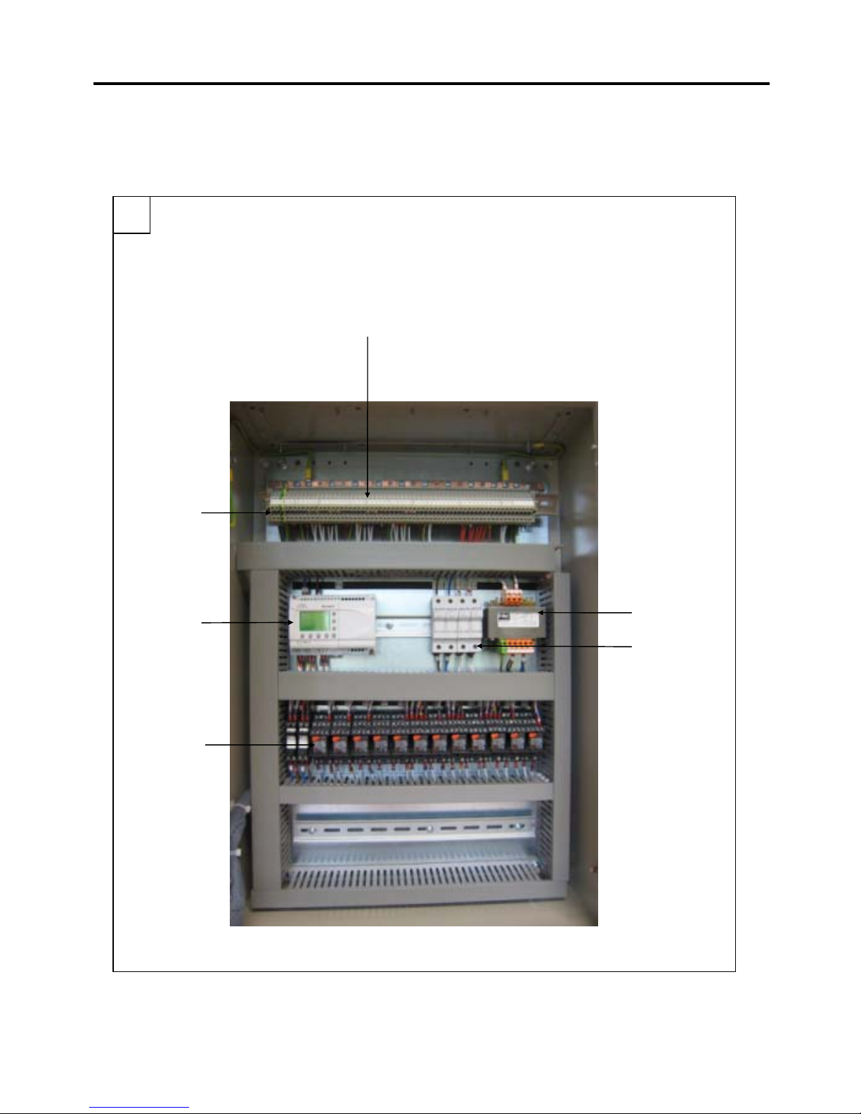
2
[Fig. 2]
B
C
A Input / output terminal
B 240VAC terminal
C Time clock
A
D Relays
E Control fuses
F Transformer
F
E
D
Page 3 of 25
Page 4
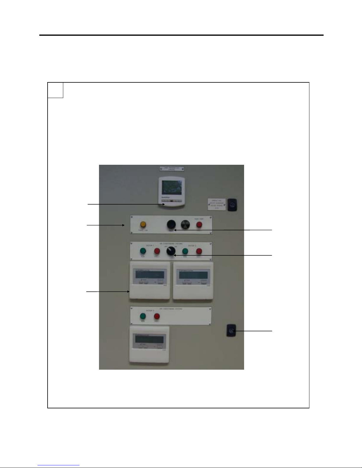
3
A Thermostat
[Fig. 3]
B Lamp status
C Remote controllers
D Door lock
Air conditioning On/Off
E
F Buzzer switch
switch
B
C
A
F
E
D
Page 4 of 25
Page 5
4
[Fig. 4]
Page 5 of 25
Page 6
5
[Fig. 5]
Page 6 of 25
Page 7

5
[Fig. 5]
Page 7 of 25
Page 8

Contents
1.
Safety precautions ....................................................................................................................................................9
2.
Overview ..................................................................................................................................................................10
3.
Panel size and weight .............................................................................................................................................11
4.
Selecting an installation site..................................................................................................................................12
5.
Installation ...............................................................................................................................................................13
5.1.
System diagram 1 – Connected to Mr Slim units .......................................................................................... 13
5.2. System diagram 2 – Connected to City Multi PFD units................................................................................ 14
6.
Electrical wiring.......................................................................................................................................................15
6.1.
Precautions on electrical wiring...................................................................................................................... 15
6.2. Types of control cables .................................................................................................................................. 15
6.3. Connecting wiring ........................................................................................................................................... 15
6.3.1. Power supply wiring................................................................................................................................... 15
6.3.2. Connecting PAC-SA89TA ......................................................................................................................... 15
6.3.3. Connecting PAC-SF40RM (for Mr Slim) ................................................................................................... 15
6.3.4. Connecting optional PAR-21MAA ............................................................................................................. 15
7.
Applicable Air Conditioning models.....................................................................................................................16
8.
Important notes .......................................................................................................................................................17
9.
Additional information............................................................................................................................................18
9.1. Heatmiser thermostat ..................................................................................................................................... 18
9.1.1. Overview.................................................................................................................................................... 18
9.1.2. Wiring diagram .......................................................................................................................................... 18
9.1.3. Technical Details ....................................................................................................................................... 18
9.2. Inlec transformer............................................................................................................................................. 19
9.2.1. Overview.................................................................................................................................................... 19
9.3. Mitsubishi Electric AL2-14MR-A alpha controller .......................................................................................... 20
9.3.1. Overview.................................................................................................................................................... 20
9.3.2. Setup.......................................................................................................................................................... 20
9.4. Mitsubishi Electric PAR-21MAA remote controller ........................................................................................ 21
9.4.1. Overview.................................................................................................................................................... 21
9.4.2. Lock the buttons ........................................................................................................................................ 22
9.4.3. Error codes ................................................................................................................................................ 23
Page 8 of 25
Page 9

g
1. Safety precautions
¾ Before installing the unit, make sure you read all the
“Safety precautions”
¾ The “Safety precautions” provide very important points
re
arding safety. Make sure you follow them
Symbols used in the text
Warning:
Describes precautions that should be observed to prevent danger of injury or death to the user.
Caution:
Describes precautions that should be observed to prevent damage to the unit.
Warning:
Carefully read the labels affixed to the main unit
Warning:
• Ask the dealer or an authorised technician to install the unit
- Improper installation by the user may result in water leakage, electric shock, or fire
• Use the specified cables for wiring. Make the connections securely so that any outside forces acting on the cables are
not applied to the terminals
- Inadequate connection and fastening may generate heat and cause a fire
• Never repair the unit. If the controller must be repaired, consult the dealer
- If the unit is repaired improperly, electric shock, or fire may result
• When handling this product, always wear protective equipment. EG: Gloves, full arm protection and safety glasses
- Improper handling may result in injury
• Have all electric work done by a licensed electrician according to "Electric Facility Engineering Standard", "Interior Wire
Regulations" and the instructions given in this manual and always use a special circuit
- If the power source capacity is inadequate or electric work is performed improperly, electric shock and fire may result
• Keep the electric parts away from any water - washing water etc…
- Contact may result in electric shock, fire or smoke
• Do not reconstruct or change the settings of the protection devices
- If the protection device is shorted or operated forcibly, or parts other than those specified by Mitsubishi Electric are used, fire or
explosion may result
• To dispose of this product, consult your dealer
Caution:
• Ground the unit
- Do not connect the ground wire to gas or water pipes, lightning rods, or telephone ground lines. Improper grounding may result
in electric shock
• Install the power cable so that tension is not applied to the cable
- Tension may cause the cable to break and generate heat which may, in turn, cause fire
• Install a leak circuit breaker, as required
- If a leak circuit breaker is not installed, electric shock may result
• Use power line cables of sufficient current carrying capacity and rating
- Cables that are too small may leak, generate heat, and cause a fire
• Use only a circuit breaker and fuse of the specified capacity
- A fuse or circuit breaker of a larger capacity or a steel or copper wire may result in a general unit failure or fire
• Be careful that the installation base is not damaged
- If the damage is left uncorrected, the unit may fall and cause personal injury or property damage
• Be very careful regarding product transportation
- Two people should be used to carry products of 20kg or more
- Some products use PP bands for packaging. Do not use any PP bands for a means of transportation
• Safely dispose of the packing materials
- Packing materials, such as nails and other metal or wooden parts, may cause stabs or other injuries
- Tear apart and throw away plastic packaging bags so that children will not play with them - If children play with a plastic bag
which has not been torn apart, they face the risk of suffocation
Page 9 of 25
Page 10

2. Overview
The run/standby panel is used to automatically change over three Air Conditioning indoor units.
The panel will be fed with a 240VAC power supply.
The panel is fitted with a day time controller switch with battery back-up and latching relay to permit two indoor units to
run for instance 7 days, after this the panel will automatically change over to the next indoor unit for 7 days etc.
The panel is designed that if one indoor unit goes to fault while running it would automatically bring in the backup
indoor unit.
The high temperature thermostat option will allow the three indoor units to run together if a high temperature exists. A
high temperature warning lamp will indicate.
The sounder & mute option will allow any fault condition received by the control panel (i.e. unit fault, or high
temperature) to initiate a sounder on the panel door. A mute button is fitted to silence the sounder.
Volt free terminals are fitted to allow fault signals to be transmitted to any external monitoring system.
The panel is supplied with accessories to interface with the Air Conditioning indoor unit:
- 3 wire adaptor to control the On/Off
- PAC-SF40RM to monitor Run and Faults with Mr Slim indoor units
Figure 1 shows the accessories supplied with the panel.
Figure 2 shows the inside of the panel.
Figure 3 shows the front panel.
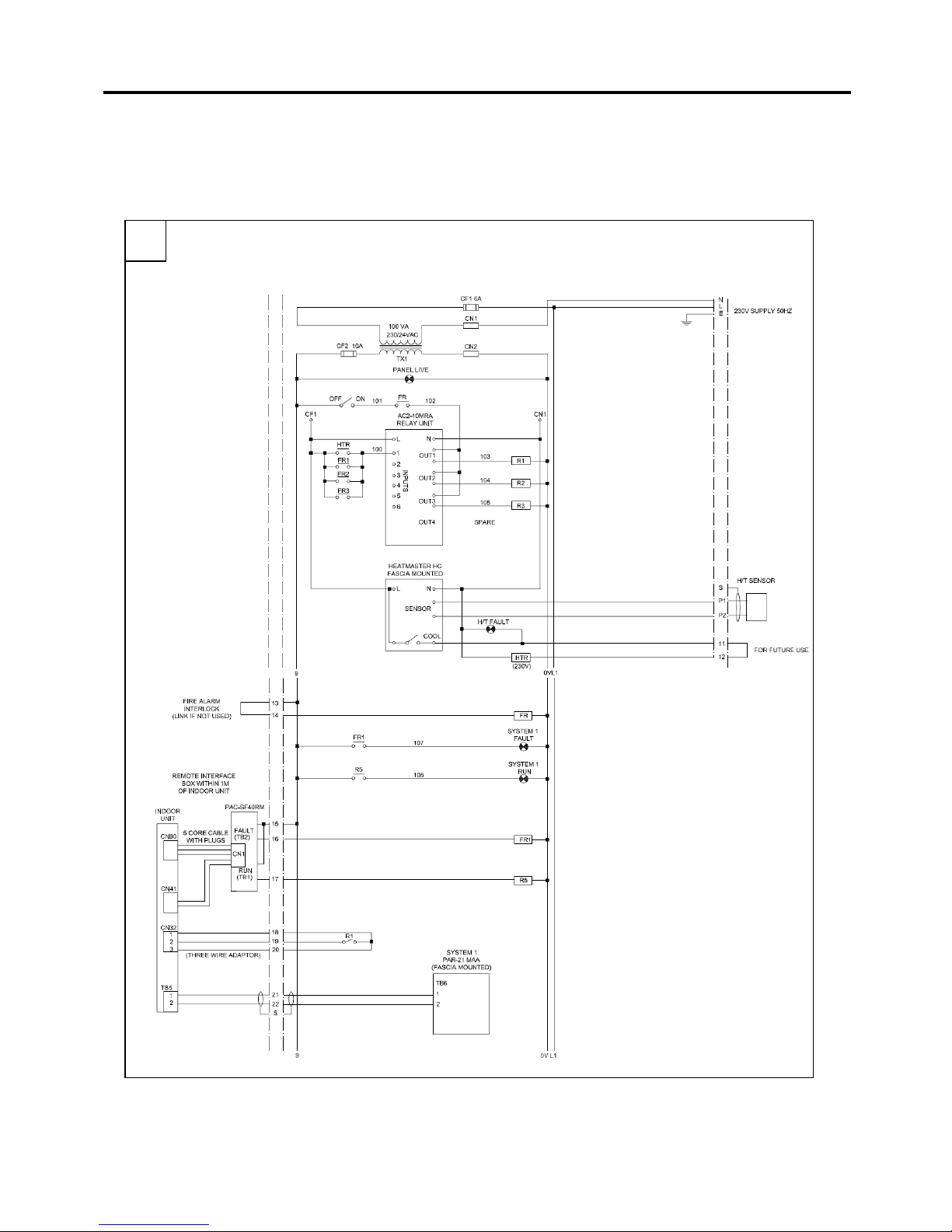
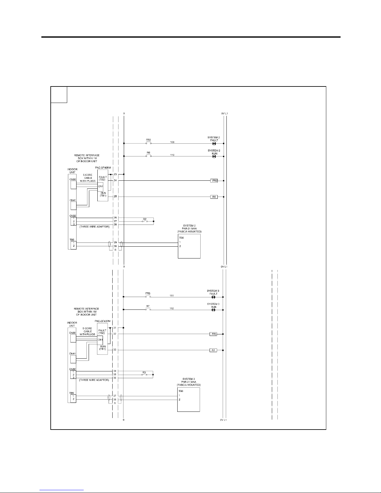
Figure 4 shows the wiring diagram of the panel.
Page 10 of 25
Page 11

3. Panel size and weight
The panel details are:
- Height 700mm
- Width 500mm
- Depth 210mm
- Weight 30Kg
Page 11 of 25
Page 12

4. Selecting an installation site
- Avoid locations in direct sunlight
- Avoid locations exposed to steam or oil vapour
- Avoid locations where combustible gas may leak, settle or be generated
- Avoid installation near machines emitting high-frequency waves
- Avoid places where acidic solutions are frequently handled
- Avoid places where sulphur-based or other sprays are frequently used
- Avoid areas of high humidity (when cooling operation is required)
- Install inside the building
- Install near the indoor units monitored and controlled
Page 12 of 25
Page 13

A
A
5. Installation
5.1. System diagram 1 – Connected to Mr Slim units
Three Mr Slim indoor units can be connected to the PANEL_RS2 via three PAC-SF40RM and three PAC-SA89TA.
POWER
SUPPLY
240VAC
HIGH
TEMP.
SENSOR
FIRE
ALARM
INPUT
Normally
Closed
SYSTEM 1
CN90 CN4 1
CN1
PAC-SF40RM
TB2
TB2
TB1
INDOOR
MR SLIM
CN32
1 2 3
TB1
PAR-21MAA
Connection
(Option)
UNIT PCB
SYSTEM 2
CN90 CN41
CN1
PAC-SF40RM
TB2
TB2
TB1
MR SLIM
TB1
INDOOR
UNIT PCB
CN32
1 2 3
PAR-21MA
Connection
(Option)
SYSTEM 3
CN90 CN41
CN1
PAC-SF40RM
TB2
TB2
TB1
MR SLIM
TB1
INDOOR
UNIT PCB
CN32
1 2 3
PAR-21MA
Connection
(Option)
HIGH TEMP. OUTPUT Normally Opened
SYSTEM 1 FAULT OUTPUT Normally Opened
SYSTEM 3 FAULT OUTPUT Normally Opened
SYSTEM 2 FAULT OUTPUT Normally Opened
COMMON FAULT OUTPUT 240VAC
L
E
N
Page 13 of 25
11
12
13
14
15
16
17
P1
P2
SCR
18
19
20
21
22
23
24
25
26
27
28
29
SCR
30
RUN/STANDBY PANEL_RS2
SCR
47
48
49
50
51
31
32
33
34
35
36
37
38
SCR
52
58
53
54
57
Page 14

A
A
5.2. System diagram 2 – Connected to City Multi PFD units
Three City Multi PFD indoor units can be connected to the PANEL_RS2 via three PAC-SA89TA. The PAC-SF40RM
interfaces are not required.
POWER
SUPPLY
240VAC
L
N
HIGH
TEMP.
SENSOR
E
P1
P2
SCR
FIRE
ALARM
INPUT
Normally
Closed
11
12
13
SCR
INDOOR
SYSTEM 2
UNIT PCB
CITY MULTI PFD
TB22 2
TB22 1
TB22 C
23
CN32
1 2 3
PAR-21MA
Connection
(Option)
24
25
26
27
28
29
30
SCR
INDOOR
SYSTEM 3
UNIT PCB
CITY MULTI PFD
TB22 2
TB22 1
TB22 C
31
CN32
1 2 3
HIGH TEMP. OUTPUT Normally Opened
SYSTEM 3 FAULT OUTPUT Normally Opened
SYSTEM 1 FAULT OUTPUT Normally Opened
PAR-21MA
Connection
(Option)
32
33
34
35
36
37
38
SCR
SYSTEM 2 FAULT OUTPUT Normally Opened
47
48
49
50
51
COMMON FAULT OUTPUT 240VAC
COMMON FAULT OUTPUT 240VAC
52
53
54
58
57
INDOOR
SYSTEM 1
UNIT PCB
CITY MULTI PFD
TB22 2
TB22 1
TB22 C
14
15
CN32
1 2 3
PAR-21MAA
Connection
(Option)
16
17
18
19
20
21
22
Please note that DIP SWITCH SW1-9 and SW1-10 must be switched OFF to activate level input with CN32 instead of
pulse input.
Page 14 of 25
RUN/STANDBY PANEL_RS2
Page 15

6. Electrical wiring
6.1. Precautions on electrical wiring
Warning:
Electrical work should be done by qualified electrical engineers / electrician in accordance with "Engineering Standards for
Electrical Installation" and supplied installation manuals. Dedicated circuits should also be used. If the power circuit lacks
capacity or has an installation failure, it may cause a risk of electric shock or fire.
- Be sure to take power from the special branch circuit
- Be sure to install an earth leakage breaker to the power
- Install the unit to prevent any of the control circuit cables (MNET transmission cables) coming into direct contact with the power cable
outside the unit
- Ensure that there is no slack on all wire connections
- Never connect the power cable to leads for the transmission cables. This will damage the transmission cable
- Select control cables from the conditions given in “Type of control cables” section
6.2. Types of control cables
Wiring transmission cables
• Cable diameter: More than 1.25 mm
2
screened cable
6.3. Connecting wiring
6.3.1. Power supply wiring
Power supply cords of appliances shall not be lighter than design 245 IEC 57 or 227 IEC 57.
Caution:
Do not use anything other than the correct capacity breaker and fuse. Using fuse, wire or copper wire with too large capacity
may cause a risk of malfunction or fire.
6.3.2. Connecting PAC-SA89TA
Connect the PAC-SA89TA to the CN32 terminal on the indoor unit. The other end of the wire must be connected to the
panel (18, 19 and 20 for system 1, 26, 27 and 28 for system 2 and 34, 35 and 36 for system 3).
6.3.3. Connecting PAC-SF40RM (for Mr Slim)
Connect the PAC-SF40RM to the CN90 and CN41 terminals on the Mr Slim indoor unit. The TB1 and TB2 terminals
must be connected to the panel (15, 16 and 17 for system 1, 23, 24 and 25 for system 2 and 31, 32 and 33 for system
3).
6.3.4. Connecting optional PAR-21MAA
Connect the optional PAR-21MAA to the MA remote controller terminal on the indoor unit. The other end of the wire
must be connected to the panel (21 and 22 for system 1, 29 and 30 for system 2 and 37 and 38 for system 3). A CN22
connector is required for each wall mounted indoor unit.
Page 15 of 25
Page 16

7. Applicable Air Conditioning models
Below is a list of Air Conditioning models that can be connected to this panel:
- Mr Slim product range
- PFD City Multi VRF product range
Please note that:
- A CN22 connector is required for each wall mounted indoor unit
- The PAC-SF40RM is not required for the PFD units
Page 16 of 25
Page 17

8. Important notes
Please note that:
- If the internal fuse fails on the panel all systems stop
- If the internal fuse fails on the panel the volt free contacts for remote alarm does not operate
- If the panel is switched off all indoor units stop
- If the panel is switched off the volt free contacts for remote alarm does not operate
- When the panel is first energised all indoor units start together
- If the power of the indoor unit is switched off, the panel will not automatically change over
Page 17 of 25
Page 18

9. Additional information
9.1. Heatmiser thermostat
9.1.1. Overview
Set Temperature
This is the temperature the thermostat is currently controlling to. At any time, you can press the Up/Down arrow key
and the display will show the set Temperature for 30 seconds.
9.1.2. Wiring diagram
9.1.3. Technical Details
Large display
Automatic blue back-light (Turns off after 30 seconds)
Flush mounting
Self Learning Optimum Start (Heating Mode only)
°C / °F Selectable
Heating, Cooling and Automatic modes available
30 minute timing increments
5 day/2 day Program
(Weekday/Weekend programming)
Up to 4 changes in room temperature
Fan speed: Auto, High, Medium, Low
Heating Output, Cooling Output, Frost protection
Easily increase or decrease the required temperature
Temperature range 05°C - 35°C
Supply: 230v / 110v
Outputs: 230v / 110v
Page 18 of 25
Page 19

9.2. Inlec transformer
9.2.1. Overview
Page 19 of 25
Page 20

9.3. Mitsubishi Electric AL2-14MR-A alpha controller
9.3.1. Overview
9.3.2. Setup
The Alpha controller is used to switch other the systems every 7 days. The switch over timing (7) can be changed but
special programming software is required. Please contact your sales office for more details.
Page 20 of 25
Page 21

9.4. Mitsubishi Electric PAR-21MAA remote controller
9.4.1. Overview
Page 21 of 25
Page 22

9.4.2. Lock the buttons
Page 22 of 25
Page 23

9.4.3. Error codes
Control Error Codes (E)
Page 23 of 25
Page 24

A-Control Error Codes (F/P)
A-Control Error Codes (U)
Page 24 of 25
Page 25

This product is designed and intended for use in the residential, commercial and light-
industrial environment.
The product at hand is based on the following EU regulations:
• Low Voltage Directive 73/23/EEC
• Electromagnetic Compatibility Directive 89/336/EEC
Please be sure to put the contact address/telephone number on
this manual before handing it to the customer.
MITSUBISHI ELECTRIC UK
MITSUBISHI ELECTRIC UK, TRAVELLERS LANE, HATFIELD HERTFORDAHIRE, AL10 8XB
Page 25 of 25
 Loading...