

Page 1
DUCTLESS SPLIT-TYPE AIR CONDITIONERS
L
I
S
T
E
D
R
MUM18NW
LCD Wireless
remote controller
LCD Wireless
remote controller
MS09NW MS09NW
TECHNICAL & SERVICE MANUAL
Wireless type
Models
MS09NW✕2 •MUM18NW
CONTENTS
No.OB202
1. FEATURES·························································2
2. TECHNICAL CHANGES ····································3
3. PART NAMES AND FUNCTIONS······················3
4. SPECIFICATIONS ··············································4
5. DATA ···································································5
6. OUTLINES AND DIMENSIONS·························9
7. WIRING DIAGRAM ··········································10
8. REFRIGERANT SYSTEM DIAGRAM··············11
9. TROUBLESHOOTING······································12
10. DISASSEMBLY INSTRUCTIONS·····················14
11. PARTS LIST······················································17
12. OPTIONAL PARTS ···········································18
NOTE:For parts list, please refer to the following manuals.
MS09NW ➝ OB192
The Slim Line.
From Mitsubishi Electric.
Page 2
1 FEATURES
MUM18NW
LCD Wireless
remote controller
LCD Wireless
remote controller
MS09NW MS09NW
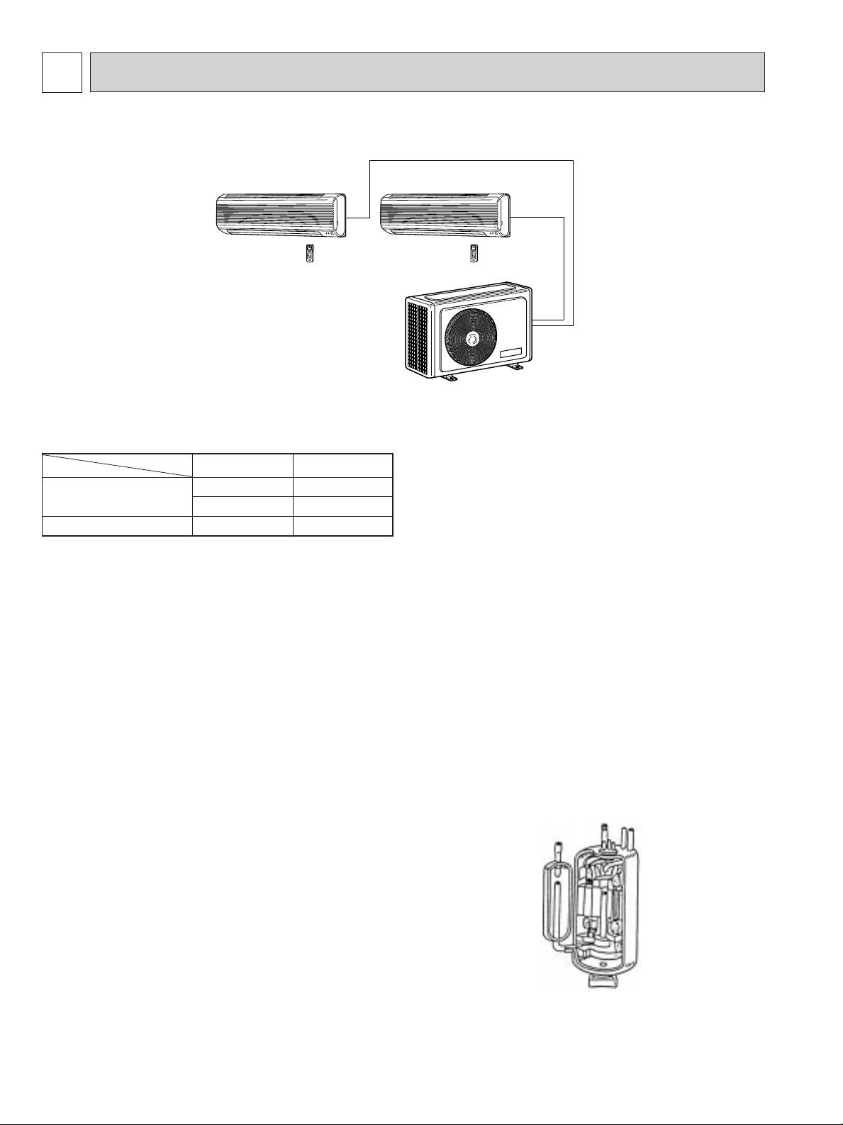
This “2 to 1” Multi system consists of a single outdoor unit with two compressors that permit up to two indoor units to
be installed separate rooms, each with its own controller.
Cooling Capacity (BTU/h)
Operation
1 Indoor Unit Operation
2 Indoor Unit Operatin
Indoor unit
MS09NW
8,400
—
8,400
MS09NW
—
8,400
8,400
1.SPACE-SAVING LAYOUT
Two indoor units are served by a single outdoor unit whose installation requires only minimum space. This allows equipment
installed outside the house to be arranged in a neat, space-saving layout.
2.FLEXIBLE INSTALLATION OF INDOOR UNITS
Each indoor unit can be connected to piping up to 49 feet in length, providing plenty of freedom in determining the best locations for installation.
3.AUTO-RESTART FUNCTION
The auto restart function restarts the equipment when power is
restored following an outage automatically. Operation resumes
in the mode in which the equipment was running immediately
before the outage.
HIGH PERFORMANCE ROTARY COMPRESSOR
The advanced design of Mitsubishi Electric’s powerful and energyefficient rotary compressor results in lower operating costs
and longer service life.
2
Page 3
2 TECHNICAL CHANGES
MSM18EW ➔ MSM18NW
1. Indoor unit has been changed.
2. Outdoor unit has been changed.
3. Remove controller has been changed.
(The timer function was changed to the clock timer function.)
4. Indoor auto vave has been adopted.
5. Outdoor fan motor has been changed.
(SGW-60F-AC➔RA6W60-AA)
6. The varistor and the fuse have been added to electric circuit of the outdoor unit.
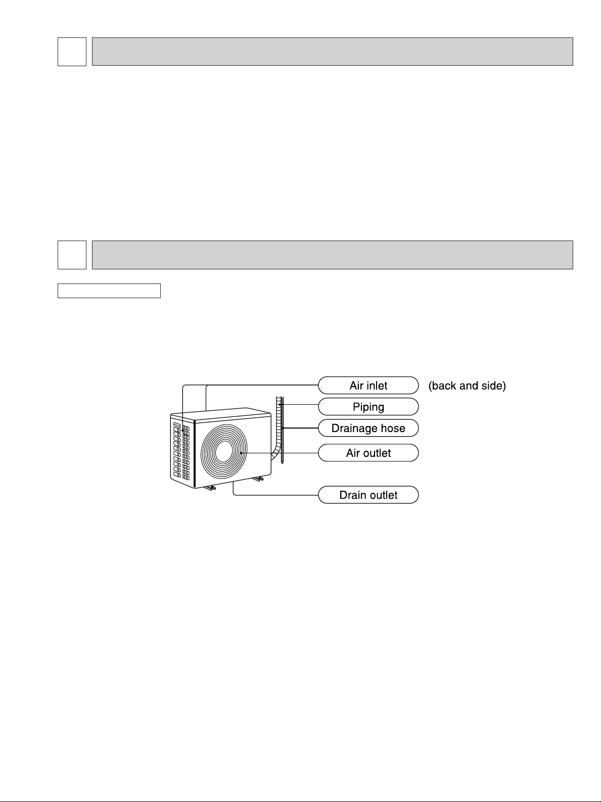
3 PART NAMES AND FUNCTIONS
OUTDOOR UNIT
MUM18NW
3
Page 4
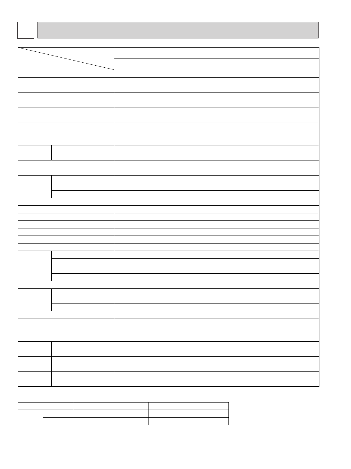
4 SPECIFICATIONS
Model
MSM18NW
SINGLE DOUBLE
Cooling capacity w1 BTU/h 8,400 8,400✕2
850 1,700
9.9
10.0
MS09NW✕2
White
115,60,1
15
0.5
0.37
208-265-328
177-226-279
–
5/8
32-1/16
7-3/16
10-13/16
18
Max. 49
Max. 25
Flared
Flared
3/8
1/4
Not supplied (optional parts)
12V DC
Wireless type
122
23-7/8
11-7/16 (12-5/8)
33-1/2
Capillary tube
37✕2
10✕2
C-R 0.98 C-S 2.21
KH122WES✕2
1.0
14+1314
15✕2
208/230,60,1
Munsell 5Y6.5/1
MUM18NW
w1 WPower consumption
EER (Double unit operation)
SEER (Double unit operation)
INDOOR UNIT MODEL
Extenal finish
Power Supply V, Hz, Phase
A
F.L.A
CFM
CFM
(Pints/h)
in.
in.
in.
in.
lbs.
V, Hz, Phase
A
F.L.A
Winding resistance (at 68˚F) "
Model
W
D
H
W
D
H
Dry
Wet
Liquid
Gas
Indoors
Outdoors
Height difference
Piping length
R.L.A
L.R.A
in.
in.
in.
in.
in.
ft
ft
lbs.
Max. fuse size (time delay)
Min. ampacity
Fan motor
Airflow
Lo-Me-Hi
Moisture removal
Cond. drain connection OD
Dimensions
Weight
OUTDOOR UNIT MODEL
External fnish
Power supply
Max. fuse sizu (time delay)
Min. ampacity
Fan motor
Compressor
Refrigerant control
Dimensions
Weight
REMOTE CONTROLLER
Control voltage (be built-in transformer)
REFRIGERANT PIPING
Pipe size
Connection
method
Between the
indoor &
outdoor units
Items
Notes w1. Rating conditions (cooling) — Inddor : 80˚FDB, 67˚FWB, Outdoor : 95˚FDB, 75˚FWB
Operating Range
Cooling
Maximum
Maximum
Indoor air intake temperature
90˚FDB,71˚FWB
67˚FDB,57˚FWB
Outdoor air intake temperature
115˚FDB
67˚FDB
4
Page 5
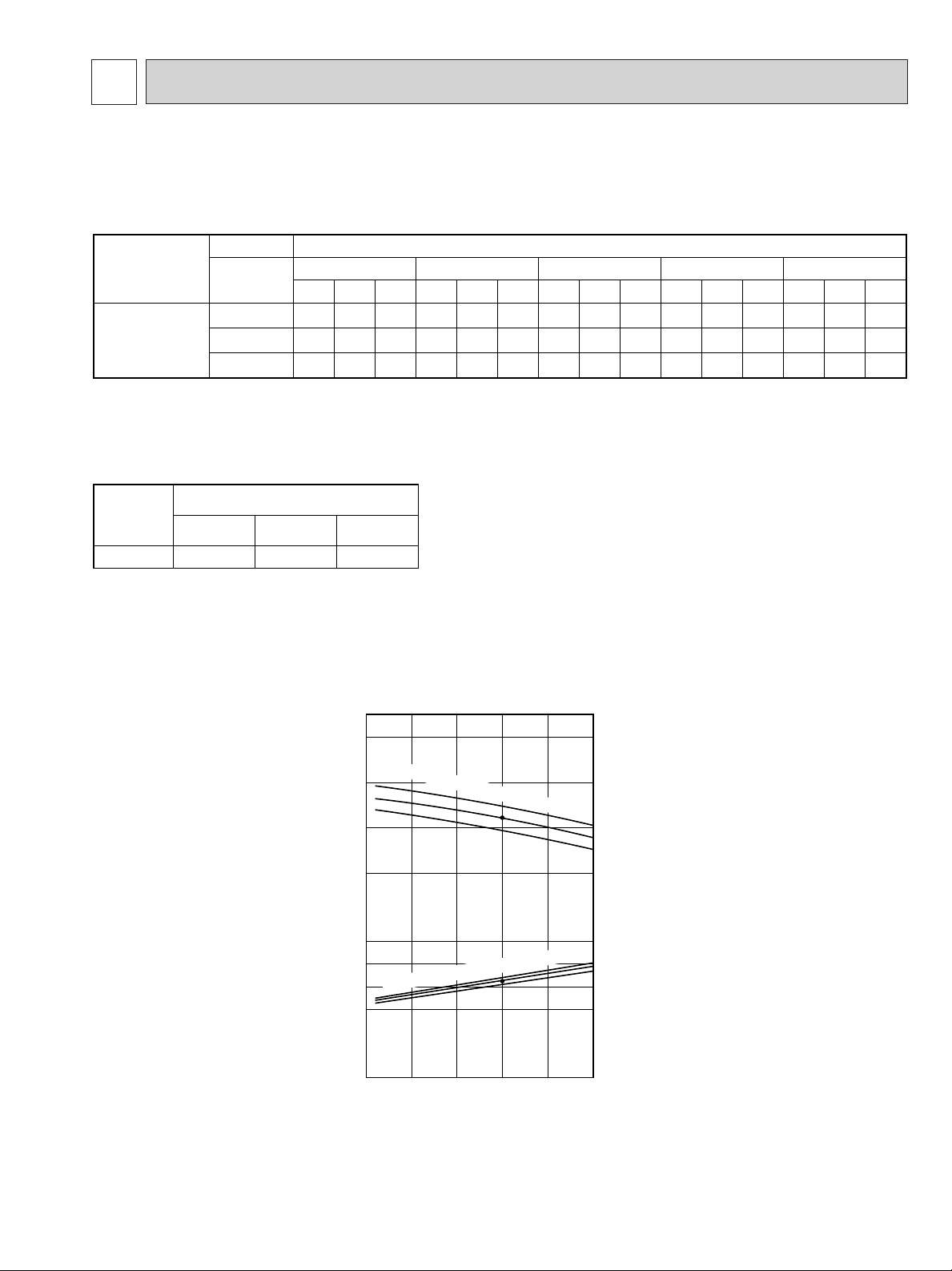
Models
Indoor air Outdoor intake air DB temperature(˚F
)
MS09NW
71
67
63
TC
10.3
9.74
9.16
SHC
5.93
6.91
7.72
TPC
0.76
0.71
0.68
TC
9.61
9.07
8.48
SHC
5.55
6.44
7.16
TPC
0.83
0.79
0.75
TC
9.03
8.4
7.9
SHC
5.21
5.95
6.66
TPC
0.89
0.85
0.81
TC
8.4
7.81
7.18
SHC
4.84
5.55
6.06
TPC
0.94
0.90
0.87
TC
7.73
7.18
6.55
SHC
4.46
5.10
5.53
TPC
0.98
0.94
0.90
IWB
(˚F)
75 85 95 105 115
Notes 1. IWB : Intake air wet-bulb temperature
TC : Total Capacity (x10
3
Btu/h), SHC : Sensible Heat Capacity (x10
3
Btu/h)
TPC : Total Power Consumption (kW)
2. SHC is based on 80˚F of indoor intake air DB temperature.
MODEL
Refrigerant piping length (one way)
MS-09NW
1.0
25ft (std)
0.954
40ft
0.927
49ft
5 DATA
65
0.6
0.8
1.0
1.2
6
8
10
12
75 85 95 105 115
Outdoor intake air DB temperature (-F)
Total power consumption (kW) Total capacity (o 10
3
Btu/h)
Cooling capacity
SHF at rating condition = 0.71
Airflow = 279CFM
Bypass Factor = 0.24
Indoor intake air WB temperature (-F)
Indoor intake air WB temperature (-F)
63
67
71
63
67
71
1.PERFORMANCE DATE (ONE INDOOR UNIT WITH ONE OUTDOOR UNIT)
MS09NW✕ 2
MUM18NW
2) COOLING CAPACITY CORRECTIONS
1.PERFORMANCE CURVE (ONE INDOOR UNIT WITH ONE OUTDOOR UNIT)
NOTE : Apoint on the curve shows the reference point.
MS09NW
MUM18NW
5
Page 6
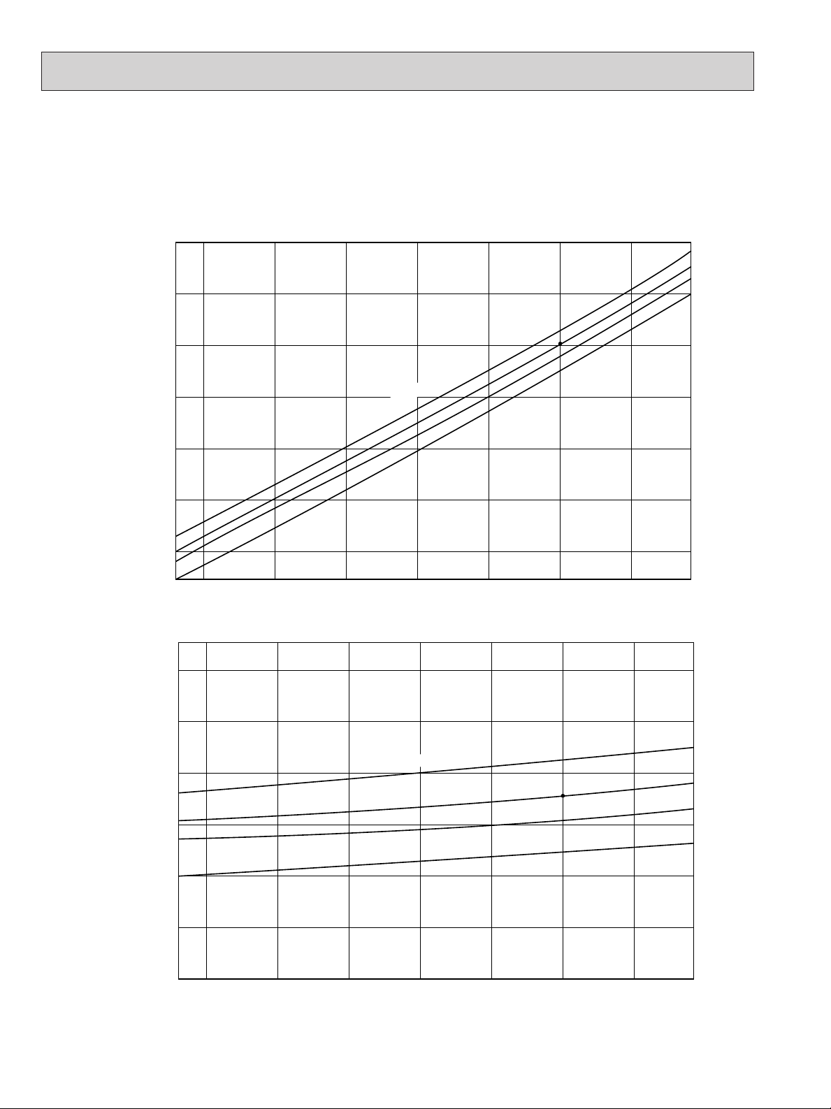
3.CONDENSING PRESSURE AND SUCTION PRESURE
68
40
50
60
70
80
90
100
(PSIG)
70
Outdoor ambient temperature
75 80 85 90 95 100 104-F
Suction pressure
70
86-F
80
75
Indoor DB temperature
68
170
180
200
220
240
260
280
300
(PSIG)
70
Outdoor ambient temperature
75 80 85 90 95 100 104-F
70
75
80
86-F
Condensing pressure
Indoor DB temperature
(ONE INDOOR UNIT WITH ONE OUTDOOR UNIT)
Data is based on the condition of indoor humidity 50%. Air flow should be set at HI. A point on the corve shows the reference
point.
MS09NW
MUM18NW
6
Page 7
2.STANDARD OPERATION DATA
Model
Total
Electrical
circuit
Refrigerant
circuit
Indoor side
Outdoor side
Item
Capacity
SHF
Input
Indoor unit model
Power supply (V,Hz,{)
Input
Fan current
Outdoor unit model
Power supply (V,Hz,{)
Input
Comp. current
Fan current
Condensing pressure
Suction pressure
Discharge temperature
Condensing temperature
Suction temperature
Comp. shell bottom temp.
Ref. pipe length
Refrigerant charge
Intake air
temperature
Discharge
air temperature
WB
DB
WB
Fan speed
Airflow (Hi)
Intake air
temperature
DB
WB
Fan speed
Airflow
Unit
Btu/h
—
kW
kW
A
kW
A
A
psi.G
psi.G
˚F
˚F
˚F
˚F
ft
—
˚FDB
˚F
˚F
˚F
rpm
CFM
˚F
˚F
rpm
CFM
MSM18NW
Single Double
Cooling
8,400 8,400✕2
0.71 0.71
0.85 1.70
MS09NW
115.60.1
0.035✕2
0.34✕2
MUM18NW
208/230.60.1(3-wire)
0.815 1.63
6.64 7.16✕2
1.0
260 270
75 75
194 191
116 118
64 54
172
25✕2
1lds 14oz✕2
80
67
60 60
57 57
1,230
279
95
—
900
1,150
3.POWER SUPPLY
MSM18NW
115V, 60Hz, 1[
115V, 60Hz, 1[
POWER SUPPLY
INDOOR UNIT
INDOOR UNIT
OUTDOOR UNIT
SIGNAL WIRE 2 wire DC12V
115V
commom
230V
115V
Field installed
208/230V, 60Hz, 1[ 3wire
7
Page 8

4.OPERATING RANGE
Indoor unit
115V 60Hz 1[
208/230V 60Hz 1[
(3wires)
Min. 198V 208V 230V Max. 253V
Min. 103v—Max. 127V
Outdoor unit
MS09NW
MUM18NW
Models Rating Guaranteed Voltage
Function
Cooling
Indoor Outdoor
78% –
DB (˚F)
80
95
67
Standard temperature
Maximum temperature
Minimum temperature
Maximum humidity
WB (˚F)
67
71
57
DB (˚F)
95
115
67
WB (˚F)
–
–
–
Intake air
temperature
Condition
Model
Outdoor unit
precharged
(up to 25ft)
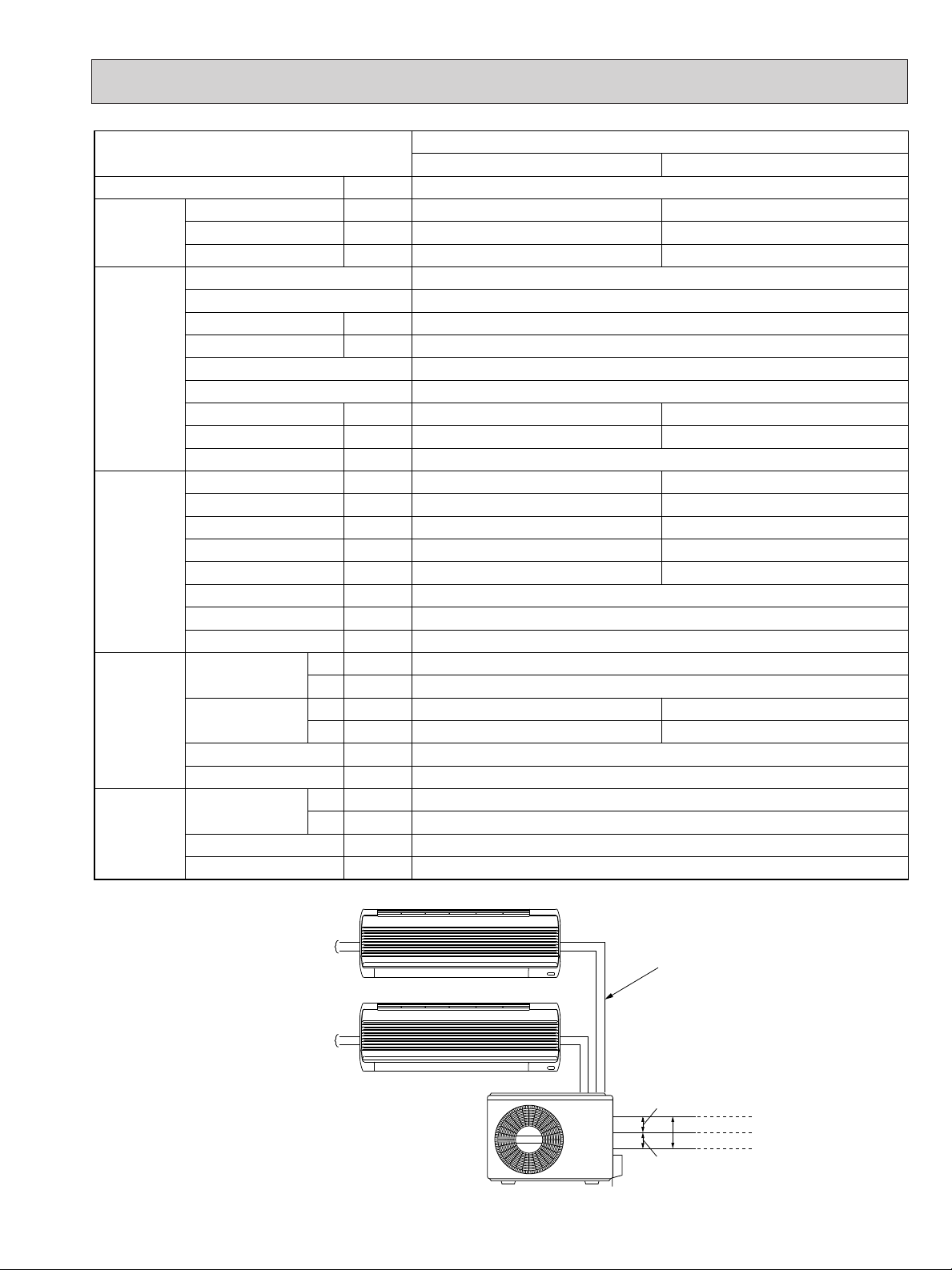
Refrigerant piping length (one way)
MS09NW✕2
MUM18NW
1 Ibs 14 oz ✕2
25ft 30ft 33ft 40ft 45ft 49ft
0 1 1 2 2 3
Indoor unit A
MS09NW
Max. Length
49ft
❋Max. Height
difference 25ft
Indoor unit B
MS09NW
Outdoor unit
MUM18NW
Max. Length
49ft
(1)
POWER SUPPLY
(2)
OPERATION
5.ADDITIONAL REFRIGERANT CHARGE (R-22(oz))
6.MAX. REFRIGERANT PIPING LENGTH & MAX. HEIGHT DIFFERENCE
MSM18NW
7.PIPING PREPARATION
1 Table below shows the specifications of pipes commercially available.
UNIT No. Pipe
and
2 Ensure that the 2 refrigerant pipes are well insulated to prevent condensation.
3 Refrigerant bending radius must be 10cm or more.
8
BA
UNIT
For liquid 1/4 1/4 Heat resisting foam plastic
For gas 3/8 1/4 0.045 specific gravity
Outside diameter Insulation
inch thickness(in)
Insulation material
Page 9

6 OUTLINES AND DIMENSIONS
REAR VIEW
Unit center
Refrigerant
pipe(Flared)
{3/8
Refrigerant
pipe(Flared)
{1/4
7/8
Wiring hole
{3-7/8
NOTE : The symbol { indicates diameter.
12-1/4
13-1/2
11-7/16
1-3/16 1-3/16 2-3/8
5-1/4
33-1/2
1/4
1-3/16
12-7/8
5-1/8
10-1/8
8
5-13/16
2 2
19-11/16
Unit
center
12-5/16
23-7/8
6-5/8
3-5/8
4 Drain holes [5/8
Air in
Air in
Air out
2-1/4
1-3/8
4 Installation anchor holes
3/8✕13/16
8-3/4
8-3/4
1-1/8
7/8
1-1/4
REQUIRED SPACE
Space for
servicing
4 in. or more
4 in. or more
36 in. or more
4 in. or more
38 in. or more
16 in. or more
[17
MODEL : MUM18NW
OUTDOOR UNIT
Unit : inch
9
Page 10

7 WIRING DIAGRAM
F
NR
115V
34
BLK
BRN
2
1
BLU
GRY
N
❈
❈
❈
BLK
ORN
YLW
X2
X1
2
2
6
6
4
4
YLW
BLU
L2
BLU
RED
TB3
TO INDOOR
UNIT No.B
CONNECTING
WIRES
DC12V
2
52
C2
GRY
VLT
2
1
TO INDOOR
UNIT No.A
CONNECTING
WIRES
DC12V
2
1
52
C1
ORN
BRN
2
1
TB2
X2
X1
5
5
3
3
WHT
RED
RED
GROUND
C3
7
7
8
8
X1
X2
52C1
52C2
4 3
BLK
TB1
L1
115V
POWER
SUPPLY
208/230V
1phase
3wires
60Hz
YLW
GRY
NR
F
GRY
WHT WHT
BLK
BRN
2
1
2
1
BLK
RED
WHT
2
1
S
MC1
MC2
MF
51C1
C1
BLK
WHT
BLK
BLK
RED
WHT
BLK
RED
BLK
GRY
1
5
4
3
YLW
ORN
RED
YLW
BLK
WHT
ORN
R
R
S
C
C
1
1
2
2
C2
51C2
❈
❈
❈
❈
OUTDOOR
MODEL MUM18NW WIRING DIAGRAM
SYMBOL NAME SYMBOL NAME SYMBOL NAME
C1,2
C3 FAN MOTOR CAPACITOR NR VARISTOR 52C1,2
F FUSE(3.0A) TB1~3 TERMINAL BLOCK
MC1,2 COMPRESSOR X1,2 FAN MOTOR RELAY
NOTE:1. Use copper conductors only (For field wiring).
2. Symbols below indicate.
3. “❈”shows the terminals with a lock mechanism, so they cannot be removed when you pull
COMPRESSOR CAPACITOR
: Terminal block, : Connector
the lead wire.
Be sure to pull the wire by pushing the locking lever (projected part) of the terminal with a finger.
10
MF
FAN MOTOR(INNER THERMOSTAT)
51C1,2
OVERCURRENT RELAY
COMPRESSOR CONTACTOR
1.Slide the sleeve.
2.Pull the wire while
pushing the locking
lever.
Page 11

8 REFRIGERANT SYSTEM DIAGRAM
Indoor unit Outdoor unit
Indoor heat
exchanger
Indoor coil
thermistor
RT12
Room
temperature
thermistor
RT11
Flared
connection
Flared
connection
Refrigerant pipe [1/4
(Option)
(with heat insulator)
Ball valve
with service port
Refrigerant pipe [3/8
(Option)
(with heat insulator)
Ball valve
Service
port
Service
port
Accumulator
Muffler
Fusible
plug
Compressor
OD0.12oID0.055o23-5/8
Capillary tube
Strainer
Indoor heat
exchanger
Indoor coil
thermistor
RT12
Room
temperature
thermistor
RT11
Flared
connection
Flared
connection
Refrigerant pipe [1/4
(Option)
(with heat insulator)
Ball valve
with service port
Refrigerant pipe [3/8(Option)
(with heat insulator)
Ball valve
Service
port
Service
port
Accumulator
Muffler
Fusible
plug
Compressor
OD0.12oID0.055o23-5/8
Capillary tube
Strainer
Flow of refrigerant
Outdoor
heat
exchanger
MS09NW✕ 2/MUM18NW
Unit : inch
11
Page 12

9 TROUBLESHOOTING
Measure the resistance between the terminals with a tester.
(Coil wiring temperature-10¡C ~ 40¡C)
Measure the resistance between the terminals with a tester.
(Coil wiring temperature-10¡C ~ 40¡C)
Part name
Compressor
Outdoor fan
motor
Check method and criterion Figure
Normal
0.86~1.06'
Opened or
short-circuited
C-R
C-S 1.94~2.39'
Abnormal
Normal
17.6~21.6'
Opened or
short-circuited
WHT-BLK
BLK-YLW
YLW-RED
9.1~11.3'
9.1~11.3'
Abnormal
BLK
REDYLW ORN
WHT
P
MUM18NW
9-1 Cautions on troubleshooting
9-1-1 Before troubleshooting, check the followings:
1) Check the power supply voltage.
2) Check the indoor/outdoor connecting wire for mis-wiring.
9-1-2 Take care the followings during servicing.
1) Befor servicing the air conditioner, be sure to first turn off the remote controller to stop the main unit, and then after
confirming the horizontal vane is closed, disconnect the breaker.
2) When removing the P.C. board, hold the edge of the board with care NOT to apply stress on the components.
3) When connecting or disconnecting the connectors, hold the housing of the connector. DO NOT pull the lead wires.
9-2 Trouble criterion of main parts
12
Page 13

Check of outdoor unit
Compressor and outdoor fan do not operate.(Only indoor fan operates.)
Start
Press EMERGENCY ON/OFF button.
3-minute time delay works.
Test mode operates for 30 minutes.
Check voltage to terminal block of outdoor unit. Is
there 115V AC to terminal block between - ,
N
L2
- ?
Yes
Check voltage to terminal block of outdoor unit. Is
there DC12V to terminal block between
Yes
Check the outdoor fan motor , compressor , relay ,
contactor , and wiring.
L1
22- 11
N
?
No
No
Yes
Check the indoor, outdoor connection.
Check voltage to terminal block of indoor unit. Is
there DC12V to terminal block between 22- 11?
Turn on outdoor power supply.
No
Check the indooor electronic control
P.C.board and wiring.
13
Page 14

10 DISASSEMBLY INSTRUCTIONS
OUTDOOR UNIT MUM18NW
OPERATING PROCEDURE PHOTOS
1. Removing of the cabinet
(1)Remove the set screws of the valve cover to remove
the valve cover as shown in Photo 2.
(2)Remove the set screws of the side panel to remove
the side panel and cabinet.
Photo 3
Photo 1
Screws
Screws
Photo 2
Screws
Screw
2. Removing the propeller
(1)Remove the propeller nut.
(2)Loosen the propeller in the rotating direction.
(3)Pull the propeller forward.
Note:
● To set the propeller, fit the cut on the shaft to the
mark on the propeller.
Photo 4
Propeller
Nut
14
Page 15

OPERATING PROCEDURE PHOTOS
3. Removing the outdoor fan motor.
(1) Remove the cabinet. (Refer to 1)
(2) Remove the propeller. (Refer to 2)
(3) Disconnect the connector remove the clamp of out-
door fan
motor lead wire.
(4) Remove the screws fixing the outdoor fan motor.
Photo 5
Photo 6
Clamp
Set screws of the relay panel
Connector
Screws
Clamp
15
Page 16

OPERATING PROCEDURE PHOTOS
4. Removing the compressor
(1)Disconnect the cord connector. (See Phot 5)
(2)Remove the set screws of the relay panel.
(3)Remove the set nuts of the terminal cover.
(4)Pull up the compressor.
(5)Pull out the lead wires from the compressor terminal
to remove overcurrent relay.
(6)Remove set nuts of the compressor base.
(7)Remove the low pressure side welded part and high
pressure side welded part using a burner.
Note:
● Before using a welder, release gas inside the unit and
make sure that the gauge pressure shows 0 kg/f.
● During welding, open the charge plug because
pressure rises due to expansion by heat
Photo 7
Photo 8
Set nuts of the terminal cover
16
Nuts
Nuts
Page 17

11 PARTS LIST
No. Parts No. RemarksParts Name
Symbol
in
Wiring
Diagram
Q,ty/unit
MUM18NW
1
2
3
4
5
6
7
8
9
10
11
12
13
14
15
16
17
18
19
20
21
22
23
24
T2W 382 342
T2W 462 232
T2W 667 249
T2W 739 245
T2W 466 509
T2W A75 301
R01 093 115
T2W 903 353
T2W 466 342
T2W E47 378
T2W 464 340
T2W 466 350
T2W 466 630
M21 B90 641
T2W 416 642
T2W 460 662
T2W 460 661
T92 513 200
T2W 739 246
M21 B93 936
T2W E42 375
M21 020 378
T2W 739 290
T2W A96 641
CONTACTOR G4F11123T-M
252C1,52C2
MF
C1,C2
X1,X2
TB1
51C1,51C2
C3
MC1,MC2
TB2,3
1
1
1
1
1
1
2
2
1
2
1
1
2
2
1
1
1
1
2
1
1
1
2
55+ 220V
8+ 220V
8+ 220V
"0.12✕"0.055✕43-5/16
CABINET
SIDE PANEL
SERVICE PANEL
OUTDOOR NOZZLE
OUTDOOR FAN MOTOR
PROPELLER
COMPRESSOR CAPACITOR
OUTDOOR FAN RELAY
OUTDOOR TERMINAL BLOCK
OVERCURRENT RELAY
OUTDOOR FAN CAPACITOR
OUTDOOR HEAT EXCHANGER
CHARGE PLUG
FUSIBLE PLUG
VALVE (LIQUID) 1/4
VALVE (GAS) 3/8
COMPRESSOR
VALVE COVER
CAPILLARY TUBE
TERMINAL BLOCK
TERMINAL BLOCK
BASE ASSEMBLY
CHARGE PLUG
RA6W60-
When servicing, cut the tube to the proper length as shown in the REFRIGERANT SYSTEM DIAGRAM see page 11.
OUTDOOR UNIT PARTS
MUM18NW
Refer to MS09EW for indoor unit.
Part number that are circled is not shown in the illustration.
17
Page 18

12 OPTIONAL PARTS
1. REFRIGERANT PIPES
The air conditioner has flared connections its indoor and outdoor sides.
Please use the optional extension pipe as follows.
MS09NW
Part No.Model
MAC - 440PI
MAC - 441PI
MAC - 442PI
MAC - 443PI
Pipe length
10ft
16ft
23ft
33ft
Cross-section
Pipe size O.D
A-Gas B-Liquid
3/8 1/4
Insulation
C 13/16
D 1-1/16
Additional
refrigerant
charge
R-22(Oz)
0
1
18
Page 19

Page 20

The Slim Line.
L
I
S
T
E
D
R
From Mitsubishi Electric.
CCopyright 1997 MITSUBISHI ELECTRIC ENGINEERING CO.,LTD.
Issued in Sep. 1997 NO.OB202 5011
New publication, effective Sep. 1997.
Specifications subject to change without notice.
Page 21

3400 Lawrenceville Suwanee Road ● Suwanee, Georgia 30024
Toll Free: 800-433-4822 ● Toll Free Fax: 800-889-9904
www.mrslim.com
Specifications are subject to change without notice.
 Loading...