

Page 1
SERVICE
&
PARTS
MANUAL
Wireless type
Models
INDOOR UNlT
MSOSEW
MS12EN
OUTDOOR UNlT
Page 2
MS-O9DW + MSOSEW
1 . lndoor unit model changed.
2. Compressor changed. KH-122WEV
-+
KH-122WES
3.
New model has Auto restart function.
/
1
1
MS-12/15DN
-+
MS12/15EN
1
.
lndoor front panel changed.
2. Suction line changes from 1 /2
0.
D. to 5/8
0.
D
.
3.
Compressor of MS15EN changed. RH207NAB
-t
RH-207NFL
4.
New model has Auto restart function. Cut the jumper wire to work the function.
I
CHANGE
POINTS
MSMI 8EW
1
.
lndoor unit model changed.
2. Compressor changed. KH-122WEV
-.
KH-122W ES
3.
New model has Auto restart function. Cut the jumper wire to work the function.
Model indication of wiring diagram and spec. name plate etc. chanegd.
Page 3
FEATURES
LCD wireless
remote controller
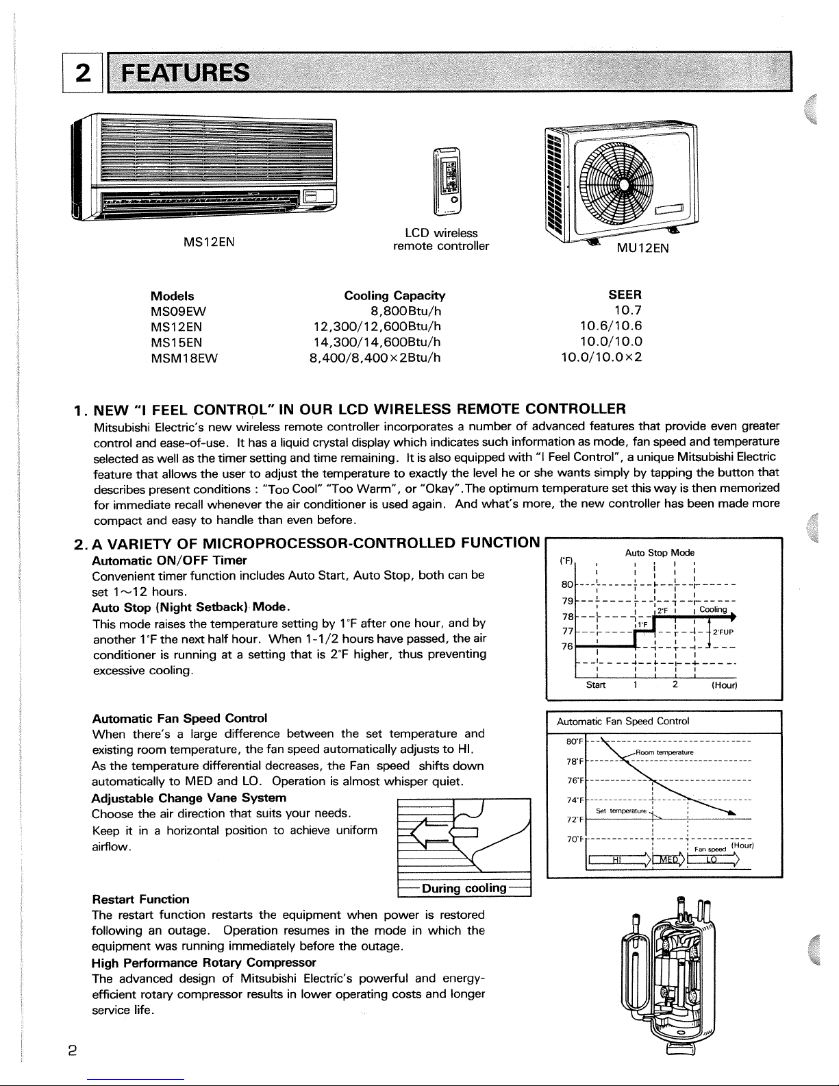
Models Cooling Capacity
MSOSEW 8,800 Btu/h
MS12EN 12,300/12,600Btu/h
MS15EN 14,300/14,600Btu/h
MSMI 8EW 8,400/8,400 x 2Btu/h
1.
NEW
"I
FEEL CONTROL" IN OUR LCD WIRELESS RER
SEER
10.7
10.6/10.6
10.0/10.0
10.0/10.0x2
dOTE CONTROLLER
Mitsubishi Electric's new wireless remote controller incorporates a number of advanced features that provide even greater
control and ease-of-use.
It
has a liquid crystal display which indicates such information as mode, fan speed and temperature
selected as well as the timer setting and time remaining.
It
is also equipped with
"I
Feel Control", a unique Mitsubishi Electric
feature that allows the user to adjust the temperature to exactly the level he or she wants simply by tapping the button that
describes present conditions
:
"Too Cool" "Too Warm", or "Okay" .The optimum temperature set this way is then memorized
for immediate recall whenever the air conditioner is used again. And what's more, the new controller has been made more
compact and easy to handle than even before.
2.
A VARIETY OF MICROPROCESSOR-CONTROLLED FUNCTION
Automatic ON/OFF Timer
Convenient timer function includes Auto Start, Auto Stop, both can be
set 1-12 hours.
Auto Stop (Night Setback) Mode.
This mode raises the temperature setting by 1 "F after one hour, and by
another 1
"F the next half hour. When 1-1 /2 hours have passed, the air
conditioner is running at a setting that is 2°F higher, thus preventing
excessive cooling.
Automatic Fan Speed Control
When there's a large difference between the set temperature and
existing room temperature, the fan speed automatically adjusts to HI.
As the temperature differential decreases, the Fan speed
shifts down
automatically to MED and LO.
Operation is almost whisper quiet.
Adjustable Change Vane System
Choose the air direction that suits your needs.
Keep it in a horizontal position to achieve uniform
aimow.
During cooling
Restart Function
The restart function restarts the equipment when power is restored
following an outage.
Operation resumes in the mode in which the
equipment was running immediately before the outage.
High Performance Rotary Compressor
The advanced design of Mitsubishi Electric's powerful and energy-
efficient rotary compressor results in lower operating costs and longer
service life.
76
I I
Start
1
2
(Hour)
Page 4
1
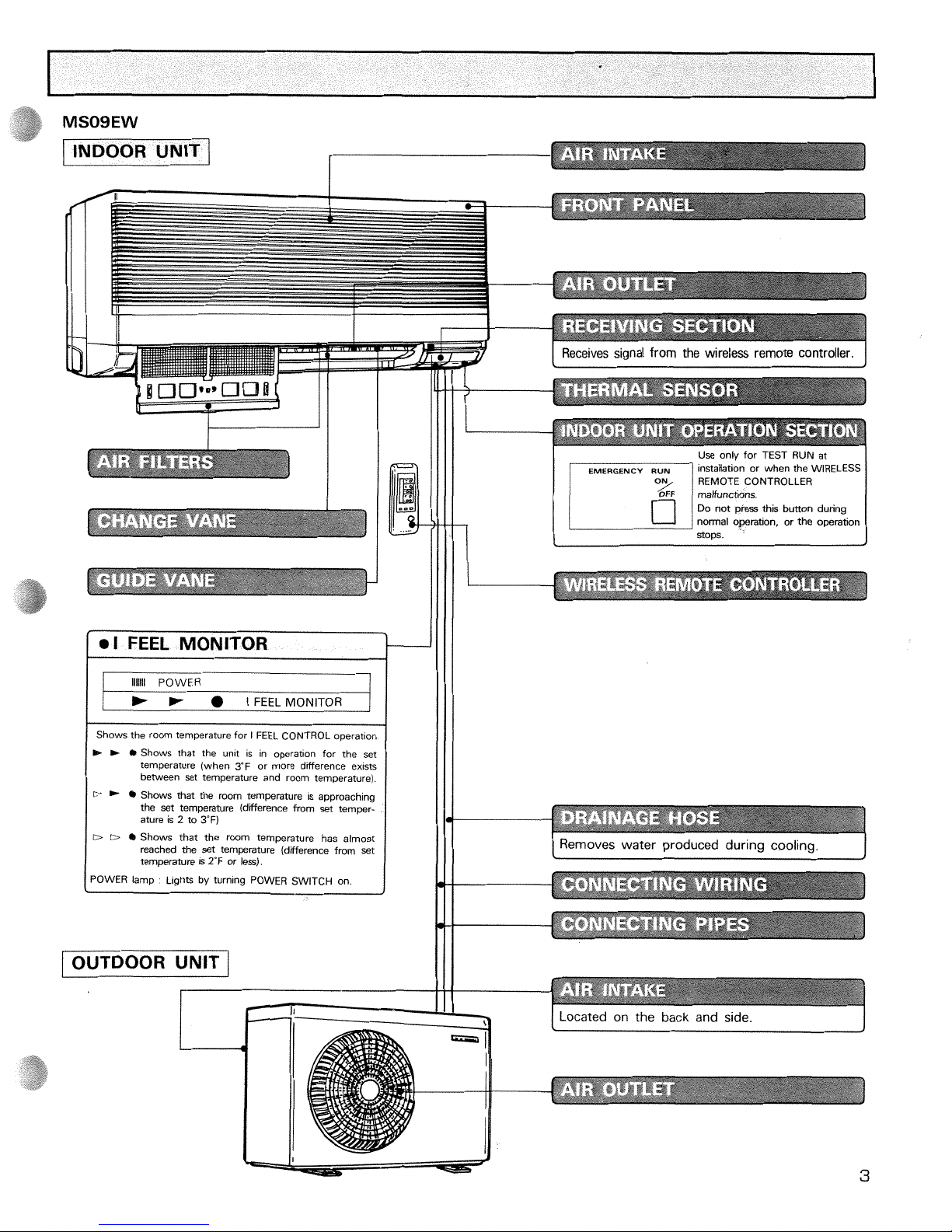
INDOOR UNIT
1
ll i 'ii
I
1
Shows the room temperature for I FEEL CONTROL
operation
R- R-
0
Shows that the unlt is in operation for the set
temperature (when 3'F or more difference exlsts
between set temperature and room temperature).
D
*
Shows that the room temperature
is
approaching
the set temperature (diierence from set temperature
is
2
to
3'F)
D
D
0
Shows that the room temperature has almost
reached the set temperature (difference from set
temperature
is
2°F or less).
I
POWER lamp
L~ghts by turning POWER SWITCH on
2
(
OUTDOOR UNIT
/
I
Receives signal from the wireless remote controller.
Use only for TEST RUN at
installation or when the WIRELESS
REMOTE CONTROLLER
maVunctlons
Do not press thls button dunng
normal
operanon,
or
the operahon
SODS.
Removes water produced during cooling.
J
I
Located on the back and side.
I
Page 5
--
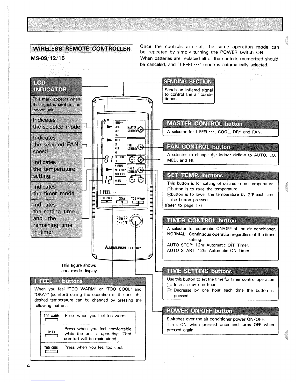
Once the controls are set, the same operatlon mode can
coNTRoLLE~
be repeated by s~mply turning the POWER sw~tch ON
-
--
When batteries are replaced all of the controls memorized should
be canceled, and
'
I
FEEL-.
-
'
mode is automatically selected.
Sends an inflared signal
to control the air
condi-
tioner.
1
This button is for setting of desired room temperature.
@button is to raise the temperature
@button is to lower the temperature by 2°F each time
the button pressed.
(Refer to page
17)
This figure shows
cool mode display.
When you feel "TOO WARM" or "TOO COOL" and
"OKAY (comfort) during the operation of the unit, the
desired temperature can be changed by pressing the
following buttons.
I
I
TO0
WARM
Press when you feel too warm.
0
while the unit is operating. That
-
comfort will be maintained.
TOO COOL
Press when you feel too cool.
I
in
A selector for automatic ON/OFF of the air conditioner.
NORMAL: Continuous operation regardless of the timer
setting.
AUTO STOP: 12hr Automatic OFF Timer.
AUTO START:
12hr Automatic ON Timer.
--
Switches over the air conditioner power ON/OFF.
Turns ON when pressed once and turns OFF when
pressed again.
Use this button to set the
tme for timer control operatlon
@
Increase by one hour
@
Decrease by one hour each tme the button is
pressed
Page 6
I
INDOOR UNIT
]
A
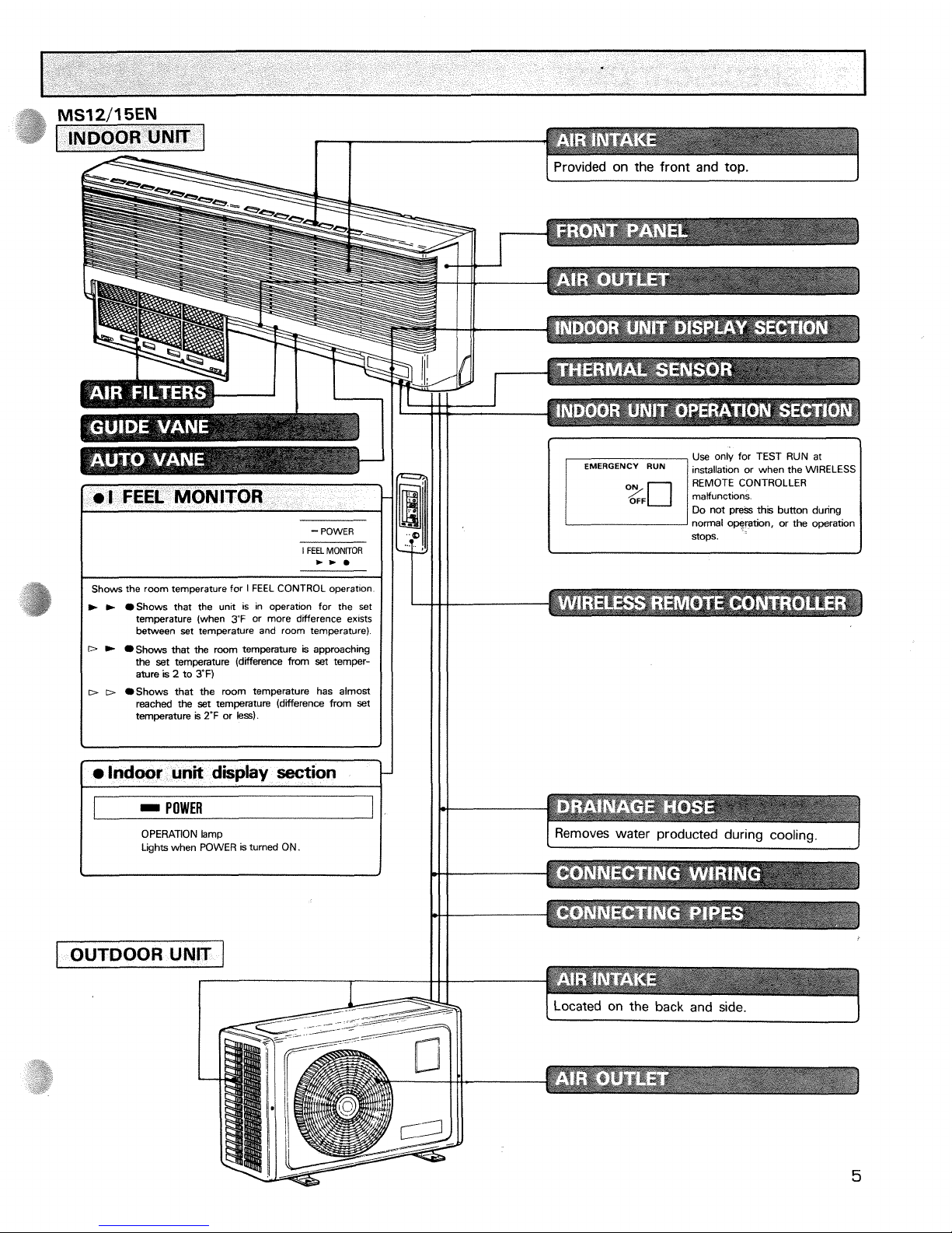
Provided on the front and top.
I
FEEL
MONFTOR
/
Shows the room temperature for I FEEL CONTROL operatton
I
m
b
Shows that the unit is in operation for the set
temperature (when
3'F
or more difference exists
between set temperature and room temperature)
D
Shows that the room temperature k approaching
the set temperature (difference from set temperature
is
2
to
TF)
I
I
D D
Shows that the room temperature has almost
reached the set temperature (difference from set
temperature
is
2'F
or
less).
-
POWER
OPERATION lamp
Lights when POWER
is
turned ON.
I
OUTDOOR UNIT
]
Use only for TEST RUN at
REMOTE CONTROLLER
Do not
pres;
th~s button dunng
normal operabon, or the operation
stops
I
Removes water producted during
cool in^.
I
Located on the back and side.
I
Page 7
-
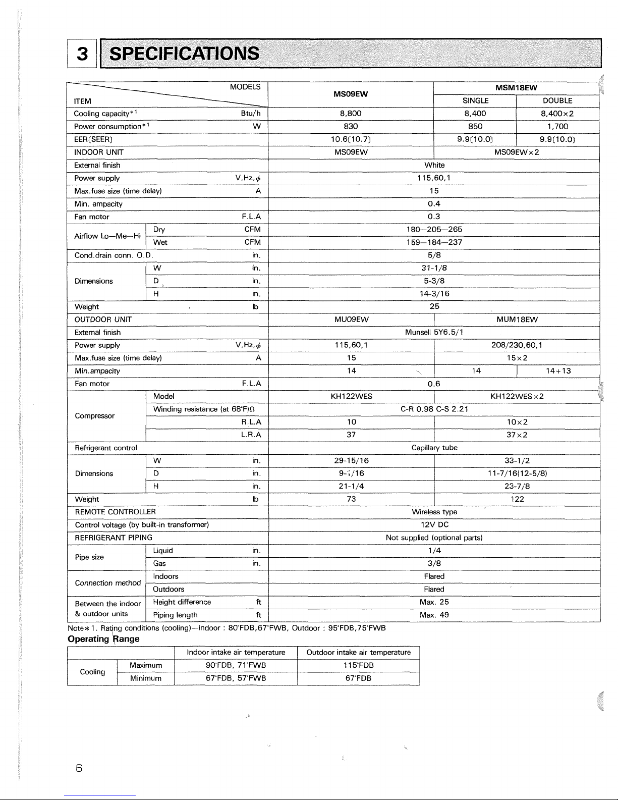
MODELS
ITEM
Cool~na cawacitv*
'
Btu/h
-.
,
I
I
I
/
power supply V.Hz,C
/
11 5,60, 1
1
MSOSEW
8.800
Power consumption*
'
W
/
830
EER[SEER)
INDOOR UNIT
External finish
/
Fan motor F.L.A
/
0.3
1
MSMISEW
850
10.6[10.7)
MSO9EW
Max.fuse size (time delay) A
/
15
SINGLE
1,700
Min. amoacity
I
Cond.drain conn. O.D. in.
1
5/8
1
DOUBLE
White
9.9(10.0)
0.4
Airflow Lo-Me-Hi
Dimensions
9.9[10.0)
IW
in.
I
31-11'8
I
8.400
MSO9EWx2
Dn/ CFM
8.400~2
180-205-265
/
H in.
1
14-3/16
I
Wet CFM
I
159-1 84-237
I
D ~n.
5-3/8
Weight Ib
I
25
/
Fan motor F.L.A
/
0.6
i-
OUTDOOR UNIT
External finish
Power supply V.Hz,C
Max.fuse size (time delay) A
I
1
/
Model KH 122WES KH 122WES x 2
MUOSEW
Munsell 5Y6.5/1
MUM18EW
11 5,60, 1
Compressor
/
REMOTE CONTROLLER
I
Wireless type
1
208/230,60,1
Winding resistance (at 68F)n
R.L.A
Refrigerant control
15
Capillary tube
Dimensions
Control voltage (by built-in transformer)
15x2
C-R 0.98 C-S 2.21
29-1 5/16
9-';/I 6
21-1/4
73
W in.
D
ln.
H in.
12V DC
Pipe size
10
33-1 /2
1 1-7/16(12-5/8)
23-7/8
122 Weight
Ib
Connection method
Note*
I.
Rating conditions (cooling)-Indoor : 8OFDB,67'FWB, Outdoor : 95FDB.75FWB
Operating kange
10x2
REFRIGERANT PIPING
Liquid in.
Gas in.
Between the indoor
&
outdoor units
I
/
Indoor intake air temwerature
I
Outdoor intake air temoerature
/
Not supplied (optional parts)
1 /4
3/8
Indoors
Height difference
ft
1
Max. 25
Piping length
ft
/
Max.
49
Flared
Outdoors
Cooling
Flared
SO'FDB, 71"FWB
67"FDB. 57"FWB
Maximum
Minimum
11 5FDB
67"FDB
Page 8
I
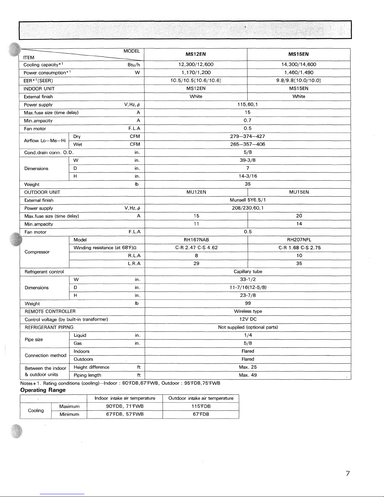
Cooling capacity*' Btu/h
/
12,300/12,600
/power consumption*
'
w
I
1,170/1,200
I
1,460/1,490
1
EER
*
'
(SEER)
I
I
/
Fan motor F.L.A
/
0.5
I
10.5/10.5(10.6/10.6)
External finish
Power supply V, Hz, 4
Max.fuse size (time delay) A
Min
.
ampacity A
9.8/9.8(10.0/10.0)
115,60,1
15
0.7
MS15EN
INDOOR UNIT
White
I
Dimensions
1
D in.
I
7
MS12EN
White
DW CFM
Cond.drain conn. O.D. in.
279-374-427
5/8
/W
in.
1
39-3/8
H
in.
Airflow Lo-Me-Hi
14-3/16
-
I
/
Max.fuse size (time delay) 15
1
20
1
Wet CFM
/
265-357-406
Weiqht Ib
/
35
OUTDOOR UNIT
External finish
Munsell 5Y6.5/1
MUl2EN
Power supply V,Hz,4
1
208/230,60,1
L.R.A
Refrigerant control
/W
in.
MU15EN
Dimensions
29
REMOTE CONTROLLER
Control voltage (by built-in transformer)
REFRIGERANT PIPING
35
D in.
H
in.
Wireless type
12V DC
Not supplied (optional parts)
Pipe size
Notes*
1. Rating conditions (cooling)-Indoor
:
80"FDBr67"FWB, Outdoor : 95FDB.75FWB
Capillary tube
33-1 /2
1 1-7/16(12-5/8)
23-7/8
Weight Ib
Connection method
Between the indoor
&
outdoor units
Operating Range
/
Indoor intake air temperature I Outdoor intake air temperature
1
99
Liquid in.
1 /4
Indoors
Outdoors
Height difference
ft
Piping length
ft
Gas in.
I
5/8
Flared
Flared
Max. 25
Max. 49
Cooling
SWFDB, 71"FWB
67"FDB. 57TWB
Maximum
Minimum
11 5FDB
67"FDB
Page 9
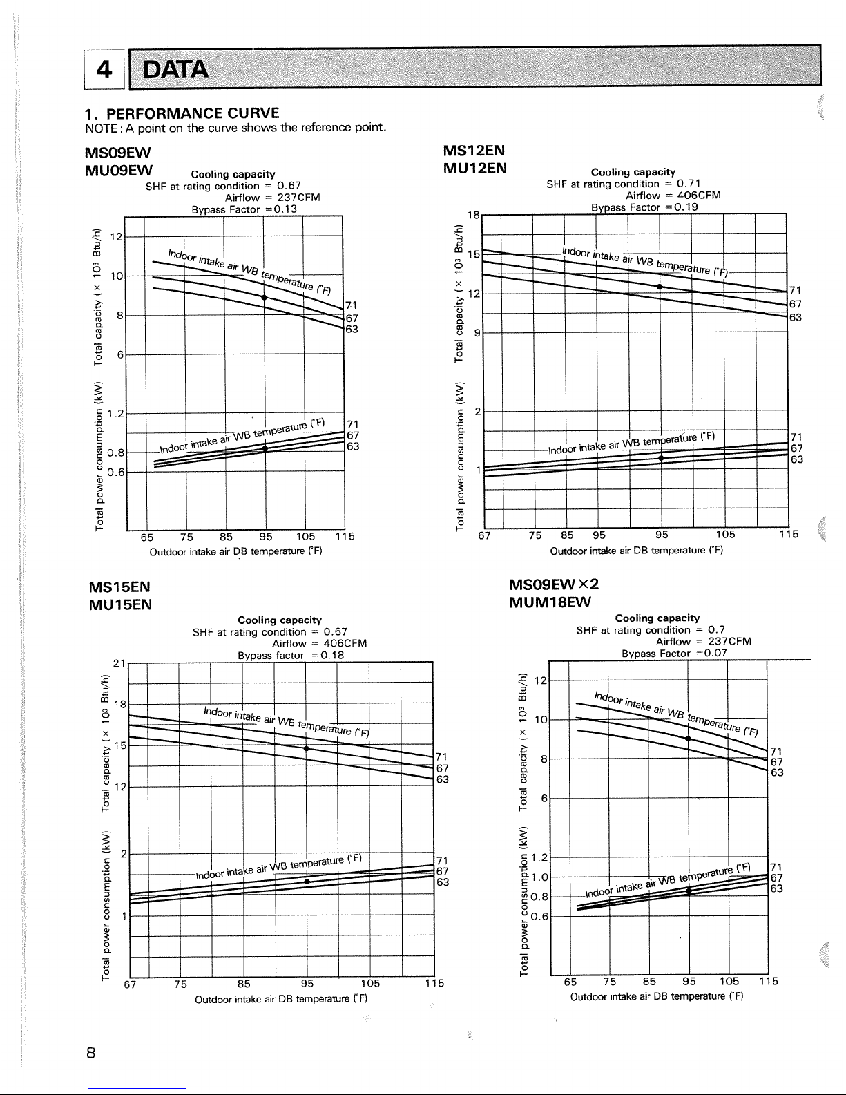
1. PERFORMANCE CURVE
NOTE
:
A
point on the
curve
shows
the
reference point.
1
Outdoor intake air DB temperature
rF)
DATA
MS15EN
MU15EN
Cooling capacity
SHF
at rating condition
=
0.67
Airflow
=
406CFM
MS12EN
MU12EN
Cooling capacity
SHF
at ratlng condition
=
0.7
1
Airflow
=
406CFM
18
e
i!
fj
15
Et
X
;
12 7 1
+
.-
0
67
m
a
63
5
9
-
m
C
2'
z
-
c
2
E!
C
e
7 1
2
67
63
81
k
3
a
-
m
C
I-
67 75 85 95 95 105 115
Outdoor intake air DB temperature
("F)
MSOSEW
x2
MUM18EW
Cooling capacity
SHF
st rating condition
=
0.7
Airflow
=
237CFM
Bypass Factor
=0.07
I
I
I
I
I I
I
Outdoor mtake air DB temperature
rF)
Outdoor ~ntake air DB temperature
("F)
Page 10
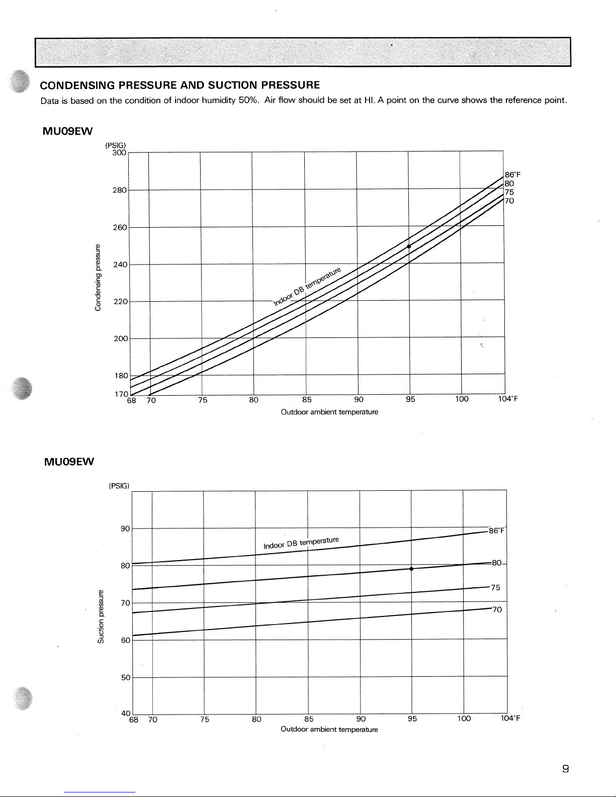
CONDENSING PRESSURE AND SUCTION PRESSURE
Data is based on the condition of indoor humidity
50%.
Air flow should be set at
Hi.
A point on the curve shows the reference point.
P!
I
,
P!
a
c
.-
I-'
3
m
85
90
95
100 1
Outdoor ambient temperature
Outdoor ambient temperature
Page 11
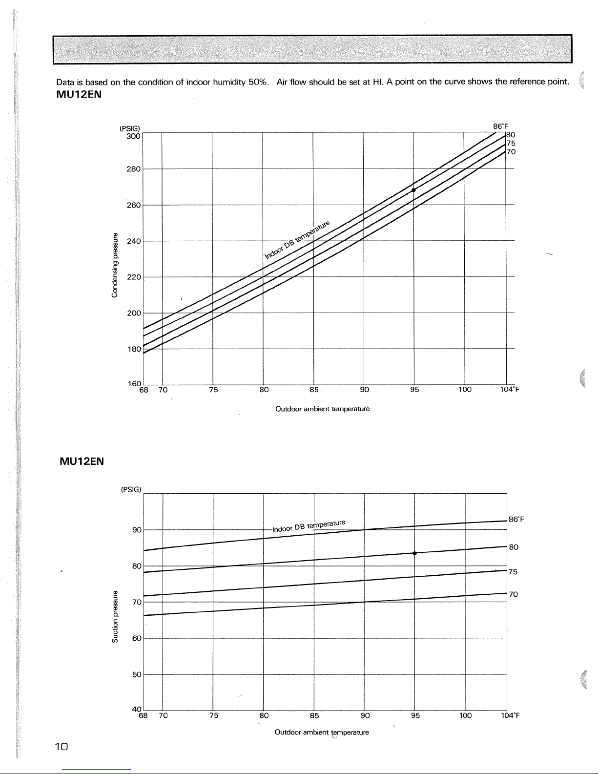
Data
is based on the condition of indoor humidity
50%.
Air flow should be set at
HI.
A point on the curve shows the reference point.
MU12EN
(PSIG)
Outdoor
ambient
temperature
Page 12
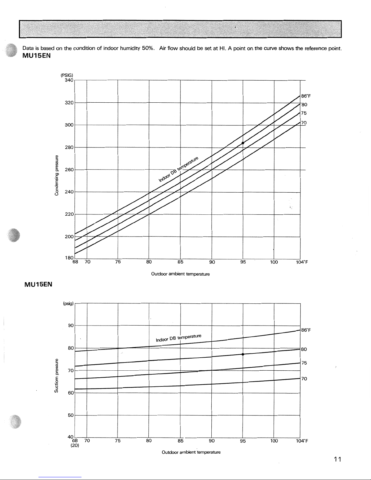
Data
is based on the condition of indoor humidity
50%.
Air flow should be set at
HI.
A point on the curve shows the reference point.
MUISEN
Outdoor ambient temperature
Page 13
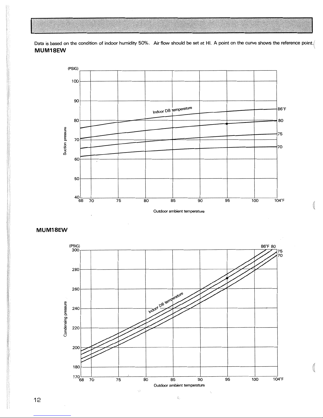
Data
is based on the condition of indoor humidity
50%.
Air flow should
be
set at
HI.
A
point on the curve shows the reference point.
(PSIG)
100
I
I I
I
0
85
90
95
100
Outdoor
ambient
temperature
Outdoor ambient temperature
Page 14
Indoor unit MS12EN
I
MS15EN
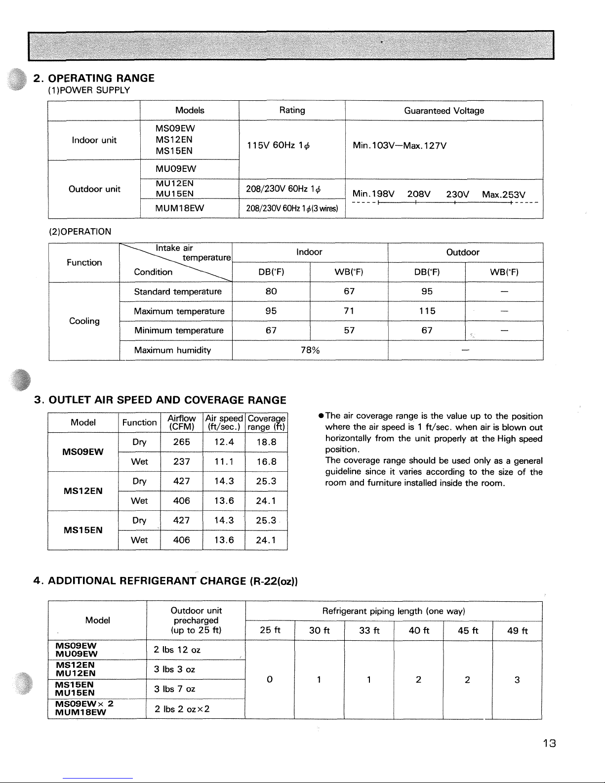
2. OPERATING RANGE
(1 )POWER SUPPLY
Min. l03V-Max. 127V
Models
Rating
Outdoor unit
Guaranteed Voltage
MUM1 8EW
Function
Min. 198V 208V 230V Max.253V
MU
12EN
MU1
5EN
2081230V 60Hz
1
d(3
wires)
Standard temperature
Maximum
tern~erature
2081230V 60Hz 14
-----
Cooling
3.
OUTLET AIR SPEED AND COVERAGE RANGE
Outdoor
DB("F)
i
WB("F)
Indoor
80
9
5
I
Maximum humidity
Model
Airflow Air speed Covera e
I I
(CFM) I ift/sec.) I ranae
I
DB("F)
I
I
I I
MSOSEW
14.3 25.3
MSl SEN
Wet 406 13.6 24.1
WB("F)
67
7
1
78%
4.
ADDITIONAL REFRIGERANT CHARGE (R-22(oz))
Minimum temperature
-
*The air coverage range is the value up to the position
where the air speed is 1 ft/sec. when air is blown out
horizontally from the unit properly at the High speed
position.
The coverage range should be used only as a general
guideline since
it
varies according to the size of the
room and furniture installed inside the room.
9 5
115
5 7 67
Model
-
-
67
-
Outdoor unit
precharged
(up to 25
ft)
I
I
I
I
I
I
I
/
3 lbs 7 oz
Refrigerant piping length (one way)
MSOSEW
MUOSEW
MS12EN
MU12EN
25 ft
2 Ibs
12
oz
3
Ibs 3 oz
30 ft
49 ft
33 ft 40 ft
45 ft
Page 15
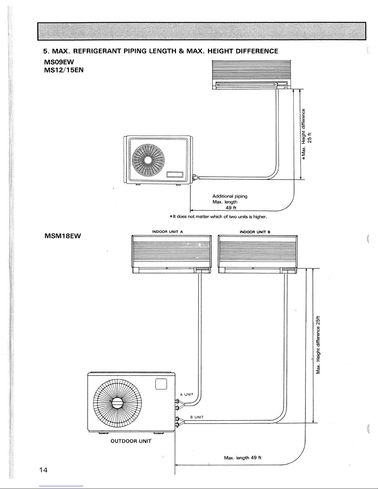
5.
MAX.
REFRIGERANT PIPING LENGTH & MAX.
HEIGHT DIFFERENCE
Additional piping
Max.
length
r
49
ft
*Jt
does not
matter
which
of
two units
is
higher.
INDOOR UNIT
A
INDOOR UNIT
I3
OUTDOOR UNlT
-
Page 16
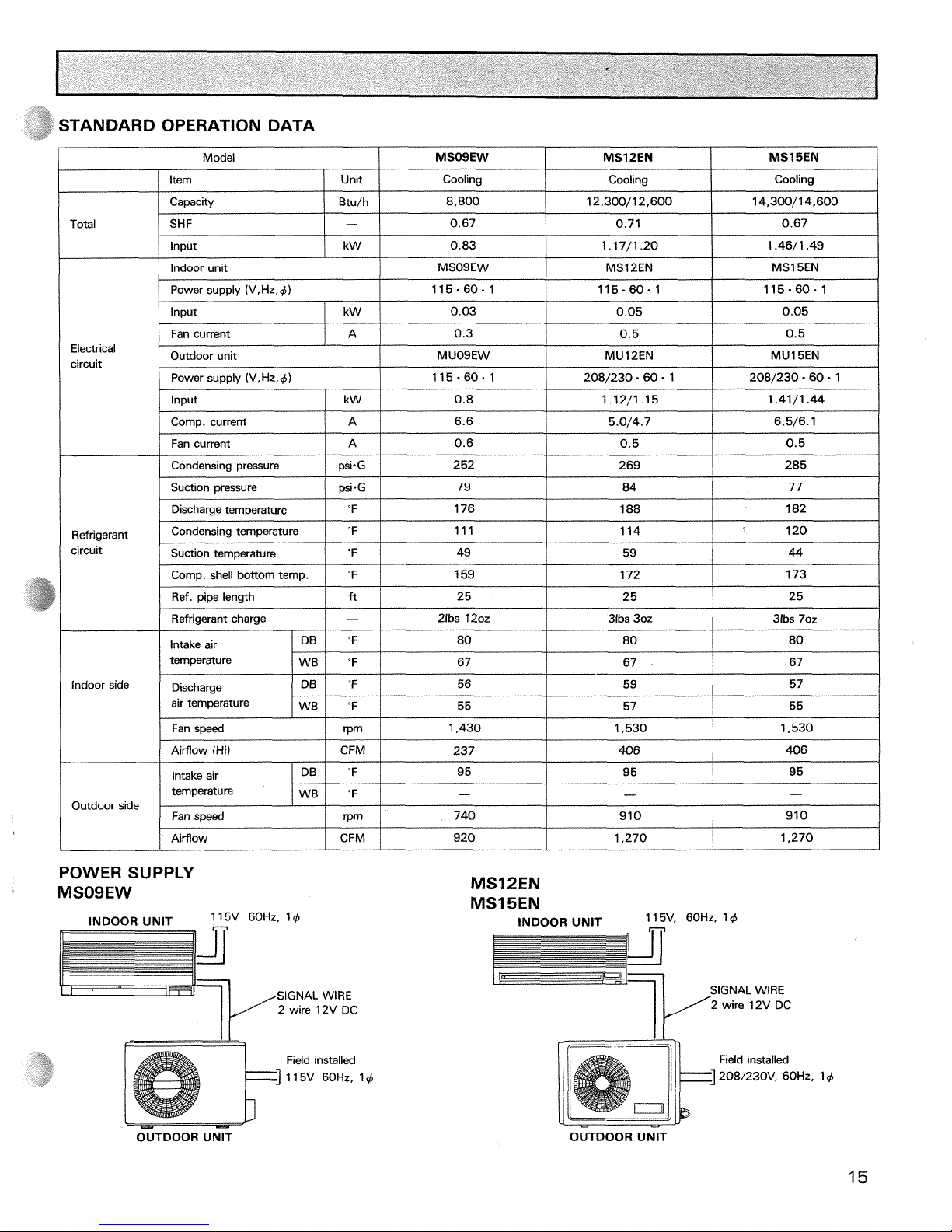
TANDARD OPERATION DATA
I
[tern
/
Unit
1
Cooling
1
Cooling
I
Cooling
I
Model
MSOSEW MSl
PEN
Total
MSl
BEN
Input
Capacity
SHF
Power supply (V,Hz,+)
kW
Electrical
circuit
I
Fan current
IAl
0.6
1
0.5
I
0.5
1
Btu/h
-
/
Indoor unit
115.60.1
Input
0.83
Input
I
kW
/
0.03 0.05
Fan current
/
Discharge temperature
I
%
I
176
1
188
I
182
I
8,800
0.67
MSO9EW
115.60.1
0.05
Power supply (V,Hz,d)
k W
Condensing pressure
Suction pressure
1.17/1.20
115-60.1
A
12,300/12,600
0.71
1.46/1.49
MSl2EN
Outdoor unit
115.60.1
0.8
6.5/6.1
Comp. current
/
A
/
6.6
psi.G
psi-G
Refrigerant
circuit
/
Refrigerant charge
1-1
2ibs 120z
1
31bs 30z
1
31bs 70z
I
14,300/14,600
0.67
MS1 SEN
0.3
5.0/4.7
Comp. shell bottom temp.
Ref. pipe length
MUO9EW
208/230.60
-
1
1.12/1.15
252
79
Condensing temperature
Suction temperature
indoor side Discharge
air temperature
208/230.60
1
0.5
1.41/1.44
"F
ft
/
Fan speed
/
rpm
I
1,430
1
1,530
I
1,530
I
0.5
MU12EN
ppp
269
84
"F
'F
Intake air
temperature
MU1 SEN
285
77
159
25
"F
'F
DB
WB
/
Airflow
I
CFM
/
920
I
1,270
I
1,270
1
111
49
Outdoor side
POWER SUPPLY
MSOSEW
172
25
80
67
INDOOR UNlT
60Hz,
'4
n
n
II
1 14
59
173
25
SIGNAL
WIRE
2 wire 12V DC
120
44
80
67
Airflow (Hi)
Field installed
1
15V 60Hz, 14
80
67
CFM
"F
"F
rpm
Intake air
temperature
MS12EN
MS15EN
INDOOR UNlT
11 5V. 60Hz. 1 4
DB
WB
SIGNAL
WlRE
237
95
-
740
Fan speed
It'
2 wire 12V DC
OUTDOOR UNlT
406
95
-
910
OUTDOOR UNlT
406
95
-
910
Page 17

Model
Item
I
unit
Total
MSMI
8EW
Input
Single
Capacity
Input
Double
kW
Electrical
circuit
I
Condensing pressure
I
P+G
I
245
I
270
I
Cooling
SHF
-
0.7 0.7
!
Btu/h
Indoor unit model
Power supply
(V.Hz.4)
Fan current
/
A
/
0.3~2
k W
Comp. current
MSO9EW
115-60.1
0.85
0.03~2
I
Outdoor unit model
Power supply (V.Hz.4)
Input
I
kW
8,400
1.70
Fan current
IAl
1
.O
A
Suction pressure
Discharge temperature
/
Comp. shell bottom temp.
I
'F
1
166
I
8,400~2
MUM
18EW
208/230 60
.
1
(3-wire)
Refrigerant
circuit
0.82
6.5
psi-G
'F
Indoor side
1.64
7.2~2
Condensing temperature
Ref.
pipe length
Refrigerant charge
76
188
I
Airflow (Hi)
/
CFM
I
237
I
79
184
'F
ft
-
Intake air
temperature
Discharge
air temperature
Outdoor side
Suction temperature
1
'F
I
63
25
21bs
202 X 2
109
50
Fan soeed
I
rpm
I
1,430
DB
WB
DB
WB
119
Intake air
temperature
POWER
SUPPLY
'F
"F
"F
"F
Fan speed
INDOOR UNlT
DB
WB
INDOOR UNlT
n
80
67
Aifflow
/
CFM
/
1,150
rpm
-------
Field installed
208/230V,
60Hz,
56
55
'F
'F
900
i
OUTDOOR UNIT
56
55
95
-
Page 18

MSOSEW
INDOOR UNlT
4 holes 7/16 x 13/16
Wall holeb2-1/2
1
Air in
OUTLINES AND DIMENSIONS
111
2-3/16 3/4
Wireless remote controller
OUTDOOR UNlT
Air out
Air out
Drain
hoseO.D.5/8
Insulation 0.0.1
-
1 /8
REQUIRED SPACE
Unit
:
inch
Wiring hole
43-7/8
Refrigerant
pipe
(Flared)
0.
D.3/8
Note
:
The symbol 4 indicates diameter
Page 19

Installation plate
LiquidlineO.D.5/46-19-11/16
Flare joint 1 /4F
Gas line O.D.3/8-16-15/16
Insulation Flare joint 5/8F
0.D.2-3/16
O.D.l-1/8
--
--3
MODEL MS12EN
Unit : inch
MS15EN
INDOOR UNlT
3-1/2
32-1 /4
3-1 /2
INDOOR UNIT REQUIRED SPACE
-
-
4 In or more
4-3/8 In or more
OUTDOOR UNlT
b
i&------
q5-i
:
i
i i
-
-
I
-
7
-
-
- - -
- - -
-.
-
-
I
-
i
P.
-
L
i
Page 20

0DEL:MUM-18EW
OUTDOOR UNIT
REQUIRED SPACE
Unit
:
inch
Air in
4
Installation anchor holes
Air
out
Wiring hole
6
3-7/8
1
Refr~gerant
ppe(Flared)
#I
14
Refr~gerant Unit center
'
ppe(Flare4
@3/8
NOTE
:
The symbol # indicates diameter.
Page 21

MODEL
MSOSEW WIRING DIAGRAM
1
TO OUTDOOR
UNIT
--
CON N ECTl NG
DC12V
--
WIRING DIAGRAM
NOTES
:
1.
For outdoor electric wiring refer to the outdoor unit electric wiring diagram.
2.
Use copper conductors only. (For field wiring)
3.
Symbols below indicate.
Q
:
Terminal block,
:
Connector.
SYMBOL
C
DSAR
F
MF
NR
SYMBOL
RTl 1
RT12
T
TB1,2
Xl l-14
NAME
INDOOR FAN CAPACITOR
SURGE ABSORBER
FUSE
(2A)
INDOOR FAN MOTOR (INNER THERMOSTAT)
VARISTOR
NAME
ROOM TEMPERATURE THERMISTOR
INDOOR COIL THERMISTOR
TRANSFORMER
INDOOR TERMINAL BLOCK
INDOOR FAN MOTOR RELAY
Page 22

MODEL MUOQEW WIRING DIAGRAM
POWER
--
--
SUPPLY L1
1
l5V
lphase
-
-
--
N
60Hz
:--'-'-A
I
IBLK:
;2
SLKn
+
GROUND
BLK
RED
MF
I
WHT
FROM INDOOR
UNIT
CONNECTING WIRES
----zFo,
----
52C
12VDC
I
MC I COMPRESSOR
/
52C / CONTACTOR
1
I
MF I OUTDOOR FAN MOTOR (INNER THERMOSTAT)
/
1
I
SYMBOL
C 1
C2
NOTE
:
Use
copper conductors only (For field wiring).
SYMBOL
TB1.2
51C
NAME
COMPRESSOR CAPACITOR
OUTDOOR FAN MOTOR CAPAClTOR
NAME
TERMINAL BLOCK
OVERCURRENT RELAY
Page 23

MS12EN
MSI~EN
WIRING DIAGRAM
WHT
SUPPLY
-
-
TO OUTDOOR
UNIT
--
CONNECTING
12VDC
--
NOTES
:
1.
For outdoor electric wiring refer to the outdoor unit electric wiring diagram.
2.
Use copper conductors only. (For field wiring)
3.
Symbols below indicate.
Q
:
Terminal block,
-1
:
Connector.
SYMBOL
C
DSAR
F
MF
NR
SYMBOL
RTl 1
RT12,14
T
TB1.2
Xll-14
NAME
INDOOR FAN CAPACITOR
SURGE ABSORBER
FUSE (2A)
INDOOR FAN MOTOR
VARISTOR
NAME
ROOM TEMPERATURE THERMISTOR
INDOOR
COIL THERMISTOR
TRANSFORMER
INDOOR TERMINAL BLOCK
INDOOR FAN MOTOR RELAY
Page 24

MODEL
MU
12EN WIRING DIAGRAM
zL
ED
ol
T
WHT
;i
sqR
POWER SUPPLY NO COM
208/230V
1
phase
60Hz
---
BLU
RED
L2
ELK
+
-
RED
GROUND
MF
ORN
FROM INDOOR UNIT
CONNECTING WIRES
12VDC
2
I
I I
MC
/
COMPRESSOR
/
52C
/
CONTACTOR
I
/
MF
/
OUTDOOR FAN MOTOR (INNER THERMOSTATI
/
1
I
r
SYMBOL
C6 1
C65
NOTE
:
Use copper conductors only (For field wiring).
SYMBOL
TB1,2
51 C
NAME
COMPRESSOR CAPACITOR
OUTDOOR FAN CAPACITOR
MODEL MU l5EN WIRING DIAGRAM
NAME
OUTDOOR TERMINAL BLOCK
OVERCURRENT RELAY
---
POWER SUPPLY
208/230V
1
phase
60Hz
BLU
RED
ELK
-
GROUND
FROM INDOOR UNIT
CONNECTING WIRES
12VDC
52C
2
/
SYMBOL
I
NAME
/
SYMBOL
I
NAME
I
I
I
C61 I COMPRESSOR CAPACITOR
/
MF
I
OUTDOOR FAN MOTOR (INNER THERMOSTAT)
I
I
C65 I OUTDOOR FAN CAPACITOR
/
TBI
,2
I
OUTDOOR TERMINAL BLOCK
1
NOTE
:
Use copper conductors only (For field wiring).
Page 25

MODEL MUM18EW WIRING DIAGRAM
lphase
3wires
POWER
SUPPLY
WHT
2
1
MF
3
5
FROM INWOR
UNIT
No.
A
CONNECTING
WIRES
l2VDC
---
FROM UNIT No. INDOOR B
---
:-@
CONNECTING
WIRES
-
--
l2VDC
(-)
SYMBOL
C1,2
C3
MC1,2
J
NOTES
:
1.
Use copper conductors only. (For field wiring)
2.
Symbols below indicate.
0
:
Terminal block,
:
Connector.
NAME
COMPRESSOR CAPACITOR
OllTDOOR
FAN
MOTOR CAPACFOR
COMPRESSOR
SYMBOL
MF
TB1-3
XI ,2
NAME
WlWOR
FAN
MOmR
INNER
THERWAD
TERMINAL BLOCK
OUTDOOR FAN RELAY
SYMBOL
51C1.2
52C1.2
NAME
OVERCURRENT RELAY
CONTACTOR
Page 26

REFRIGERANT SYSTEM DIAGRAM
.
I
Indoorunit
1
Refngerant pipe 43/8
(Opt~on)
(with heat insulator)
connection
1
Unit:
inch
1
Outdoorunit
1
Strainer
i_
I
/I
connection
(I
I
Refrigerant pipe 4 1 /4 Ball valve
Capillary tube 0~0.12 x ID0.063 x47-1/4
(Option) with service
(with heat insulator) port
f
Indoor unit
1
Refnqerant pipe Q5/8
Room temperature
thermistor RTl1
b
I
Service
ared connectio
Accumulator
Muffler
rn
Compressor
I
Outdoor unit
1
Flared connection
MU12EN ODO. 12 xID0.063 X27-9/16
\
I/
MUISEN OD0.12X1D0.063X23-5/8
Refrigerant pipe41 /4
"
Ball valve
(Option) (with service port)
(wkh heat insulator)
+Flow of refrigerant
NOTE:
The symbol
d,
indicates diameter.
Page 27

MS09EW x2/MUMl8EW
Unit: inch
1
Indoor
unit
]
1
Outdoor
unit
1
Refrigerant pipe +3/8
(Option)
(with heat insulator)
'fE53
I-.+&
Flared
'
Ball valve
connection
ODO. 12
X
100.055 X23-5/8
bith heat insulator)
U
Room
I
I
11
temperature
Refrigerant pipe +3/8
IO~tion)
;!',--$t.a463m
C-
Indoor coil
I I
11
thermistor Refrigerant pipe 4 1
/4
Ball valve
Capillary tube Strainer
RT11 (Option) with service
port
I
Room
temperature
thermistor
RTl 1
-
Capillary tube Strainer
Refrigerant pipe
+
1
/4
Ball valve
(Option) with service
port
(with heat insulator)
--.
Flow of refrigerant
Page 28

MICROPROCESSOR CONTROL
Wireless Remote Controller
SENDING SECTION
I
LCD
INDICATOR
rooi
DRY
MASTER CONTROL
button
LO
FAN CONTROL
HI
bunon
St1 TEMP
SET TEMP.
bunons
AUTO
STOP
TIMER CONTROL
AUTO
SPRT
bunon
HOURS
TIME SETTING
bunons
TO0 COOL
OKAY
TOO
WARM
POWER
bunon
I
'I FEEL" CONTROL bunons
This figure shows
I
FEEL CONTROL mode display.
[
INDOOR UNIT DISPLAY SECTION
I
I
FEEL MONITOR
bb.
POWER
...
...
Once the controls are set, the same operation mode can
be
repeated by simply turning the POWER switch ON.
Indoor unit receives the signal with a beep tone.
When the system turns off,
"3
min. time-delay function" will
operate to protect system from over load and compressor will
not restart for
3
minutes.
1.
"I
FEEL
CONTROL" operation
(1 ) Press POWER button on the remote controller. Power
lamp of the indoor unit will tum on with a beep tone.
(2)
Press the MASTER CONTROL button to set
"I
FEEL
. . .
".
And I FEEL MONITOR lamp lights with a beep tone.
(3)
The operation mode is decided by the initial room
temp. at starting up the operation.
1
Initial Room Temp.
/
Mode
!
*Once the mode is fixed, the mode will not change by
room temp. afterwards.
*Under the AUTO START timer operation, the mode is
determined according to the room temperature
1
hour
before the set time.
When the system is stopped with the POWER button on
the remote controller, and restarted within
1
hour in
"I
FEEL CONTROL" mode, the system operates in previous
mode automatically regardless of the room temp.
When the system is restarted after 1 hour, the operation
mode is decided by the initial room temperature at start-up
of the operation.
Example
Previous operation
COOL mode of
"I FEEL CONTROL"
COOL mode of
or COOL mode
Page 29

(4)
The initial set temperature is decided by the initial room temperature for the first 2 min. after the system starts.
tG
UI
JTROL"
/
Less than 76°F
Initial room temperature
minus 2 deg("F)
Initial set temperature
Model
%
1
After the system restarts by the remote controller, the system operates with the previous set temperature regardless
of the initial set temperature.
Initial room temperature
(5)
1
FEEL CONTROL buttons
In
'I
FEEL CONTROL" mode, set temperature is decided by the microprocessor based on the room temperature. In
addition, set temperature is controlled by
I
FEEL buttons when you feel too cool or too warm, and when you feel
comfortable the button fixes the comfortable temperature.
When the
I
FEEL button is pressed, I FEEL MONITOR lamp on the indoor unit flickers for a second with beeps.
*Variable control
When the
TOO COOL
or
TOO
WARM
-
button is pressed, the set temperature is changed based on the room temperature. As the
set temperature range is variable, this is called "Variable control". The variable control operates only in
'I
FEEL
CONTROL" mode.
In DRY mode of
'I
FEEL CONTROL". the set temperature range is fixed
+
2
deg ("F).
:=!.-.To raise the set temperature by
2
deg.
--
3
deg.('F)
OKAY
--.To fix and memorize the comfortable present temperature
0
WARM--^^
lower the set temperature 2 deg.
--
3
deg. ('F)
0
-
I
FEEL
MONITOR
lamp
on the indoor unit
-
When I FEEL CONTROL button is pressed, I FEEL MONITOR lamp on the indoor unit flickers with beeps and shows the
temperature control condition.
I
FEEL MONITOR lamp
\,
\I
\I
b-b
Shows difference between set temperature and room temperature is more than 3 deg. ("F)
t\
I,
I
\
During this condition, I FEEL button is not available.
Wait for about 15 min.
D
Shows difference between set temperature and room temperature is 2 deg.
-3
deg. (OF)
\I
The buttons are available.
DD*
Shows room temperature has almost reached set temperature. The difference is less than 2°F.
The buttons are available.
NOTE
During
"I
FEEL CONTROL" operation, thermostat (SET TEMP.) is not available. Use
"I
FEEL CONVKN-"
buttons to set temperature
Once the set temperature is set, the microprocessor memorizes the temperature and the system restarts at
the same set temperature.
*The set temperature range is 61 to 88F in COOL
DRY mode of
'I
FEEL CONTROL".
When the main power is turned off, the settings are canceled. Initial set temperature will be decided as
shown in the above table.
Page 30

-
COOL mode of
"I
FEEL CONTROL"
-
ON ON
Compressor
&
OFF
1
OFF
Outdoor fan motor
I
ON
Runs all \he time in cooling mode
Indoor fan motor
NOTE Coil frost prevention during COOL mode of
'I
FEEL CONTROL".
There are two types of controls in coil frost prevention.
@
Temperature control
<MS09>
When the indoor coil thermistor RTI 2 reads 47°F or below for 5 min., the coil frost prevention starts. The compressor stops
and the indoor fan operates at set speed or AUTO speed for 5 min. After that if
RTI 2 still reads 47°F or below, this function
is prolonged until
RTI 2 reads over 47°F.
<MS12/15>
MS12/15 have two indoor coil thermistors RTI 2 and RTI 4. When RTI 2 (or RTI 4) reads 50°F or below for 5 min., the
coil frost prevention starts. The compressor stops and the indoor fan operates at set speed or AUTO speed for 5 min. After
that, if
RT12 (or RT14) still read(s) 50°F or below, this function is prolonged until RT12 (or RT14) read(s) over 50°F.
@
Time control
When the three conditions below have been satisfied for 1 hour and 45 minutes, the compressor stops for
3
minutes and
the coil frost prevention mode starts.
(a)The compressor is on continuously.
(b)The indoor fan speed is LO or MED.
(c)The room temperature is below 79°F.
If the compressor turns off half way, the accumulated time is cancelled.
Time counting starts from the beginning when the above three conditions are satisfied again.
If the indoor fan speed becomes
HI or the room temperature exceeds 79"F, time counting stops temporarily.
Time counting restarts from the stop point when the above three conditions are satisfied again.
The indoor fan operates at the set speed.
*Indoor fan operates at the set speed
by
FAN CONTROL switch.
Followings are' the fan speed in AUTO.
Room temperature minus set temperature
:
4 to 7 deg.("F) or over-.........--HI
-
- - - - - - - - -
-
Room temperature minus set temperature : 2 to 7 deg.("F)
..--.-....-.....--.-.
MED
----.-
t
4
deg. 7 deg
Room temperature minus set temperature : 2 to 3 deg.('F) or below -....-.LO
- - - - -
f
2deg.
3deg.
-
DRY
mode of
"I
FEEL CONTROL"
-
The system uses the same refrigerant circuit as the cooling circuit for dry operation.
The compressor and the indoor fan are controlled by both temperature and the microprocessor.
By such controls, indoor flow amounts will be reduced in order to lower humidity without much room temperature decrease.
The operation of the
comp. and indoor fan is as follows on the next page.
1.
When the room temperature is 73°F or over
Compressor operates by temperature control and time control.
For the first 2 min. the system is FAN mode and the indoor fan operates at very low speed.
Then 2 min. later, the room temperature is read as the initial temperature.
@Set temperature is controlled to fall by 2°F as initial set temperature.
Page 31

@When the thermostat is ON, the compressor repeats 8 rnin. ON/3 rnin. OFF cycle operation.
When the thermostat is OFF, the compressor repeats 4 rnin. OFF/1 min. ON cycle operation.
indoor and outdoor fans operate in the same cycle with compressor.
lndoor fan speed is very low.
2.
When the room temperature is under
73°F.
Compressor works in 2 min. ON/3 min. OFF cycle while the thermostat is on.
When the thermostat is OFF, the compressor repeats 4 rnin. OFF/1 min. ON cycle operation.
lndoor and outdoor fans operate in the same cycle with compressor.
lndoor fan speed is Very low
Operation Time
Chart
1st ON
Example
7
Thermostat
!
lndoor fan OFF
I
VLO
speed
Outdoor fan OFF
/
compressor
2
min.
j
I
OFF
I
OFF
, , , , , , ,
,
, , , ,
,
,
m,
ON
, ,
, ,
OFF
!
2
0
2,
NOTE *Coil frost prevention during DRY mode of
"I
FEEL CONTROL"
The operation is same as coil frost prevention during COOL mode of
"I
FEEL CONTROL" except the indoor
fan speed is VLo.
*In DRY mode of
"I
FEEL CONTROL", FAN CONTROL switch is not available.
2.
COOL
operation
(1 ) Press POWER button.
Power lamp of the indoor unit turns on with a beep tone.
lndoor fan continues to operate regardless of thermostat's OFF-ON.
Coil frost prevention is the same as COOL mode of
"I
FEEL CONTROL".
(2)
Select COOL mode.
(3) Set the SET TEMP. button.
F
The setting range is 61 to 88°F.
95.
*"I
FEEL CONTROL" buttons are not available.
(4) The indoor fan runs continuously to provide venti-
lation and prevent air stratification.
90-
3.
DRY
operation
85-
(1)
Press POWER ON/OFF button.
E.
Power lamp of the indoor unit turns on with a beep tone.
$
80:.
(2)
Select DRY mode.
8.1
(3)
lndoor fan operates at VLO speed.
E.
8-
(4)
After 2 rnin. the microprocessor reads the room temperature
5
75:
and decides the set temperature. Set temperature will be as
shown on the chart.
70-
Thermostat
(SET
TEMP.) is not available.
The other operations are same as DRY mode of
"I
FEEL CONTROL".
65.
30
65
70
75 80 85 90 95
100'F
Set temperature and ~nitial room temperature
/
/
/I
/
/
/
Page 32

4.
FAN
operation
(1) Press POWER ON/OFF button.
(2) Select FAN mode.
(3) Press SET TEMP. button to select the desired temperature.
The indoor fan stops when room temperature is lower than the set temperature
(4) Select the desired fan speed.
Followings are the fan speed in AUTO.
Room temperature minus set temperature
:
4 to 7 deg.("F) or over.....-...-..HI
- -
- - -
-
-
-
Room temperature minus set temperature : 2 to 7 deg.("F)
......-.....-.-.....-MED
- - -
-
-
Room temperature minus set temperature : -2 to 3 deg.("F)
..-...............
LO
---
Room temperature minus set temperature : -2 to 0 deg.("F) or below
..-...
Only indoor fan operates.
Outdoor unit does not operate.
SOFT SLEEP CIRCUIT
5.
TIMER
4
1 . AUTO STOP operation
AUTO STOP mode has "SOFT SLEEP" circuit which provides comfortable
temperature control for sleeping.
3
(1) Set the TIMER CONTROL to AUTO STOP.
2
4..
(2) Set the time. Time setting is in 1 hour units for up to 12 hours.
8
ti
2
(3) "SOFT SLEEP" circuit operates in COOL mode. By this circuit, system
operates at the set temperature for the first 1 hour. Then, in COOL mode
the set temperature rises by 1 deg. half-hourly to
2
deg. range.
1
In
"I
FEEL CONTROL and DRY mode, the circuit does not operate.
Set temperature
1 Hour
2
Hours
2.
AUTO START operation
(1) Set the TIMER CONTROL button to AUTO START.
(2) Set the time. Time setting is in 1 hour units for up to 12 hours.
NOTE
TIMER setting will be canceled by power failure or breaker functioning.
6.
EMERGENCY-TEST operation
When the remote controller is missing, has failed or the batteries run down, press the emergency run on/off switch on the
front of the indoor unit. The unit will start and the operation lamp will light.
The first 30 min. of operation will be the test run operation. This operation is for servicing. The indoor fan runs at high speed
and the system is in continuous operation.
The thermostat does not operate and the timer is reset to normal.
After 30 min. of test run operation the system shifts to emergency run operation with a set temperature of 75°F in cooling.
The fan shifts to MED speed.
This operation continues until the emergency run
on/off button is pressed or a button on the remote control is pressed, then
normal operation will start.
The coil frost prevention circuit operates in this mode.
EMERGENCY RUN
EMERG~NCY
ON/OFF
button
Page 33

1.
AUTO RESTART FUNCTION
When the indoor unit is controlled by the remote controller; the operation mode, set temperature, and the fan speed are
memorized by the indoor electronic control P.C. board. After power failure, the unit operates automatically when power is
restored. In case of unit operated in
'I
FEEL CONTROL"
mode before power failure, the operation is not memorized. In
'I
FEEL CONTROL" mode, the operation is decided
by
the initial temperature. Refer to page 28.
How to set AUTO RESTART FUNCTION
Cut the jumper wire JR84
Operation
a) If main power
(ACI 15V) is cut, the operation settings remain.
b)
When power is restored, the unit restarts in previous mode 3 minutes later without remote controller.
c) Even if power is cut for about 0.5 seconds, auto restart works.
Note
a) If main power is cut while AUTO START/STOP timer is set, the timer setting is cancelled when auto restart function
works.
b) If the unit was off by the remote controller before power failure, auto restart function does not work as the power button
of the remote controller is off.
[q
2.
How to reconstruct for individual operation
SERVICE FUNCTION
A
maximum of 4 units with wireless remote controllers can
be
used in a room. In this case, reconstruction of
P.C.
boards is needed
to operate each unit individually by each remote controller.
The transmission code is changed by the reconstruction.
1 . Reconstruction of the remote controller
P.
C.
board.
Remove batteries before reconstruction.
/-
&
I&
are printed on the board.
Originally, chip parts are fitted on J10/J20 side and there is no chip parts on the other side.
Remove the chip parts of
J
10/J20 side and connect Jumper wire to J11 /J21 side according to the number of the
individual control.
Either J 10 or J 1
1
/J20 or J2 1 should be attatched for normal operation.
Standard reconstrucion table
1
/
1 unit operation
1
2 units operation
1
3
units operation
1
4
units operation
1
/
No. 1 unit No construction
1
Same as left
I
Same as left
I
Same as left
I
Reconstruction of the indoor electronic control
P.
C
.
board.
JR05
JR06
is printed on the board. Refer to TEST POINT VOLTAGE in the manual for the print point.
Jumper wire are fitted to JR05 and JR06.
Reconstruct JR05 and JR06 to corespond to the remote controller board.
L
No.2 unit
No.3 unit
No.4 unit
I
I
1 unit operation
1
2 units operation
1
3
units operation
1
4
units operation
/
-
-
-
No. 1 unit
No.2 unit
/
No.4unit
1
-
I
-
I
-
I
Remove JR05, JR06
I
Same as left
Remove
J 1 0
Connect
to
J
1 1
-
Connect
to
~2
1
Remove
J20
-
-
No.3 unit
Same as left
Same as left
Remove
J10, J20
Connect
to
J
1 1 ,
J2
1
No construction
-
J
-
Same as left
Remove JR05
-
Same as left
Same as left
Same as left
Same as left
Remove JR06
Same as left
Page 34

Self
check
function
This function is to show defective point by lighting or flashing of the indoor unit power lamp, or
"I
FEEL
monitor lamp (monitor
LED). If trouble written in the below table occurs during operation, the self check result is indicated.
The abnormal cation
indication is reset by pressing the power on/off button of the remote controller and when the unit is on.
10
1I_;
*
Before taking measures make sure that the symptom reappears, for accurate troubleshooting.
TROUBLE
SHOOTING
Self Check Table
;m:
Flash
0
OFF
Abnormal point
indication
Symptom
Detect
methd
Cause
Repair
lndoor coil thermistor
,
POWER
D
~1.1
I
FEEL
MONITOR
lndoor unit power turns off.
Detects lndoor coil thermistor short or open circuit every
2
sec. during operation.
Thermistor defect
Connector disconnecting
0
Connector misconnecting
lndoor control P.C. board defect
Check thermistor calibration.
0
Reconnect connector.
0
Check indoor board.
Page 35

(I
)
Operation does not start
(Stan)
I
Check power supply voltage on indoor
terminal block.
Is there 1 15V AC between indoor
Turn on power supply
terminal block
[IT]
-
?
Yes
/
\
Does+signal mark appear for an instant
on Remote Controller when POWER button is
pressed
?
Yes
,
Is battery voltage
over 2.4V
?
Does emergency run start by
No
pressing EMERGENCY button
?
Yes Replace Remote controller
Check Electronic control P.C. board voltage.
a)
CN102
@ - @
:
12-20VAC
b) CN109@+
-
0-
:
5V
See the TEST POINT DIAGRAM VOLTAGE on page
37.
Replace Electronic
control P.C. board.
.
Does indoor unit receive signal
with a beep tone when POWER
Replace Receiver board.
button is pressed
?
Check power P.C. board
qvOltage.
CN204
0
-
@
:
Replace
Power P. C. board
Page 36

Compressor and outdoor fan do not operate (Only indoor fan operates)
Press EMERGENCY ON/OFF bunon
3 min
.
time-delay function operates.
Test mode operates for 30 min.
MS12/15EN
Is there 230V AC between
-
a
on
outdoor terminal block
?
No
L
Tum on outdoor
MSOSEW power supply.
Is there
1
15V AC between
-
m.
Yes
Check voltage to contactor 52C
Yes
Is there 1 2V DC between
(
+
'
-
2
-
1
of
c
Check Contactor 52C
outdoor term~nal block TB2
7
If defectwe replace.
*
No
is there 12V DC between.li(+)
-
211-1
of
Yes
Check
cont~nu~ty
of
Indoor term~nal block TB2
?
L
~ndoor and outdoor untt
control wiring.
J
Replace the power P. C. board.
Check resistance of room temp. thermistor RT1 1.
NO
e
Replace Room temp.
See the thermistor resistance on page
37.
thermistor RT11.
i
Yes
Is there 12V DC between CN 1020-
-
@
+
NO
on the Indoor electronic control P.C. board
?
*
Replace the indoor electronic
control P.C. board
Yes
Page 37

RELAY OPERATION
NOTE : When the compressor is OFF,
"3
min. time-delay circuit" operates
MODE
COIL FROST PREVENTION mode are as follows
THERMOSTAT
]
52C CONTACTOR
1
INDOOR FAN RELAY
THERMOSTAT
Indoor
fan
relav mode
52C CONTACTOR
OFF for 5 min. After
that, OFF is prolonged
until indoor coil thermistor reads termina-
tion temp.
1
Indoor fan speed
I
Relay turning ON
1
HI
I
OFF
I
All fan relavs are off
I
XI4
LO
INDOOR FAN RELAY
Auto or set speed
Very low speed
XI
2
MED
VLO
XI
1
i
XI
3
I
Page 38

TEST POINT DIAGRAM AND VOLTAGE
MSOQEN
MS12/15EN
In/out signal circuit
Power supply
25-30V
AC
Ir
In/out siganl
output
24-OV
DC
Indoor electronic control
P.C.
board
I
Reconstruction of indoor
:;i
$
Defrost thermistor
-
"---Auto restart
function switch
Room temperature
thermistor
electronic control
P.
C. board
I
$.
Room temperature
Thermistor RTl 1
20
5
15
Y
-
E
E
'3
10
d
5
60 70 7780 90 100
Defrost
Thermistor RT12.RT14
Temperature
('F)
Temperature
('F)
Page 39

MSOSEW
Power P.C. board
Transformer
Output lnput Output
12-20V
AC
1 15V
AC
25-30V
AC
-,----.-
aQQIaB a
I
lnput
1 15V
AC
In/out signal
12-1 4V
DC
Indoor fan motor relay signal
Page 40

NIS12/15EN
Power
P.C.
board
Transformer
Output Input
12--20V AC 1 1 5V AC
In/out signal
~~2550 - LD2570
lnput
1
i5~
AC
12-16V DC
Page 41

OPTIONAL PARTS
1.
REFRIGERANT PIPES
The air conditioner has flared connections on its indoor and outdoor sides.
Please use the optional extension pipe as follows.
Applicable
Parts No. Pipe length
models
Pipe Size
0.
D
A.Gas (in.)
B.
Liquid (in.)
I
Additional
refrigerant
Page 42

THIS PAGE LEFT INTENTIONALLY BLANK.
Page 43

STANDARD PARTS
INDOOR UNIT PARTS
MSOSEW
Page 44

Parts Name
I
I
1 I T2W 901 000 / FRONT PANEL ASSEMBLY
Symbol
1
Q'tvhnit
1
in
Wiring Remarks
Diagram MSO9EW
1
Air filter wire is included
2 T2W 901 067 SCREW CAP 2
3 T2W 901 100 AIR FILTER 2
4
/
M21 K17 022 / AIR FILTER WIRE
1 1
2
I
5 1 T2W 901 004 / SWITCH DOOR
1 1
1
I
6 1 T2W 901 234 1 BOX ASSEMBLY
1 1
1
I
7 T2W 901 975 CORNER BOX 1
8 M21 BOO 970 INSTALLATION PLATE 1
9
1
T2W 901 081 1 ELECTRICAL BOX 1
10
1
T2W 901 339 1 TRANSFORMER T 1
11
/
T2W 901 443 1 SWITCH P.C. BOARD
1 1
1
I
12 T2W 712 781 LAMP HOLDER 1
13 T2W 901 329 DISPLAY P.C. BOARD 1
14
/
M21 534 375 1 INDOOR TERMINAL BLOCK
1
TB1
I
1
1
15 T2W 901 375 INDOOR TERMINAL BLOCK
TB2 1
16 T2W 901 450
ELECTRONIC CONTROL P.C. BOARD 1
17 T2W 901 440
POWER P.C. BOARD 1
18 T2W 901 300 INDOOR FAN MOTOR MF 1 RA4W11-
AA
19 / M21 BOO 302 / LINE FLOW FAN
I
1
1
1
20 M21 453 505 RUBBER MOUNT 2
21 T2W 41 6 382 FUSE (2A) F 1
22
1
T2W 901 235 1 NOZZLE ASSEMBLY
1 1
1
I
I
I
1
I
I
23 1 T2W 901 040 1 VANE 1
24
1
M21 BOO 041 1 VANE HOLDER
1
I
1
I
25 M21 B03 703 DRAIN HOSE 1
26 M21 NO0 468 RECEIVER P.C. BOARD 1
27
/
T2W 901 320
/.
SLIDE KNOB
1
I
1
1
28 T2W 723 307 ROOM TEMPERATURE THERMISTOR RTl
I
1
29
/
T2W
A04 308 INDOOR COIL THERMISTOR RT12 1
30
/
T2W 676 620 / INDOOR HEAT EXCHANGER
1
1
1
1
31
M21
BOO 509 BEARING MOUNT
1
32
M21
BOO 504 SLEEVE BEARING
1
Page 45

OUTDOOR UNIT PARTS
MUOSEW
1 2 1
M21 478 297 1 TOP PANEL
1 1
1
1
I
No.
1
Parts Name
CABINET ASSEMBLY
Parts No.
T2W 464 232
3
4
1 7 1
T2W 457 641 / CHARGE PLUG
I
1
2
I
I
5
6
1 8 1
T2W 416 642 1 FUSIBLE PLUG
I I
1
I
I
Symbol
Wiring
In
Diagram
T2W 41 6 521
M21
A00 245
T2W 41 6 630
T92 513 200
1
12 1 T2W 41 6 509 / OUTER NOZZLE
1
I
1
1
I
Q'ty/unit
MUO9EW
1
FAN GUARD
SERVICE PANEL
9
10
11
1
13 / T2W 464 290 / BASE ASSEMBLY
1
I
1
1
I
Remarks
1
1
OUTDOOR HEAT EXCHANGER
COMPRESSOR
1
14 1 T2W 679 301 / OUTDOOR FAN MOTOR
1
MF
I
1
/
SGW-26C-CB
I
M21 987 936
T2W 460 661
T2W 460 662
MC
CAPILLARY TUBE
VALVE (GAS)
VALVE (LIQUID)
15
16
19
1
T2W 679 350 / OUTDOOR FAN MOTOR CAPACITOR
I
C2
/
1
/
5,uF
250V
1
1
17
18
KH-122WES
1
1
1
M21 601 501
T2W 81
1
375
40.12~
40.063 x 126
M21 534 375
T2W 903 353
20
21
PROPELLER
OUTDOOR TERMINAL BLOCK
22
OUTDOOR TERMINAL BLOCK
COMPRESSOR CAPACITOR
T2W 464 340
T2W 382 342
TB
1
I
44
T2W 460 246
1
1
TB2
C1
OVERCURRENT RELAY+
CONTACTOR
VALVE COVER
1
1
51 C
52C
1
55,uF 220V
1
1
Page 46

OUTDOOR UNIT
MUM18EW
Refer
to
MSOSEW
for
PARTS
indoor unit
Parts No. Parts Name
I
I
1 I T2W 382 342 1 CONTACTOR
Symbol Q'tvhnit
in
Wiring
Remarks
Diagram MUM
18EW
52C1.52C2 2
2 T2W 462 232 CABINET 1
3 T2W 667 249 SIDE PANEL 1
4
/
T2W 739 245 1 SERVICE PANEL
1 1
1
I
1
5 T2W 466 509 OUTER NOZZLE 1
6 T2W 466 301 OUTDOOR FAN MOTOR MF 1 SGW-6OF-AC
7
/
R01 093 11 5 1 PROPELLER
1
I
1
1
I
7T2W 903 353 COMPRESSOR CAPACITOR
I
I
I
C1, C2 2 55j4 F 220V
1
9 / T2W 466 342 1 OUTDOOR FAN RELAY
I
x1,x2
/
2
1
I
800 375 OUTDOOR TERMINAL BLOCK TB 1 1
464 340 OVERCURRENT RELAY 51C1 ,51C2 2
OUTDOOR FAN CAPACITOR C3 1
1
8pF 220V
OUTDOOR HEAT EXCHANGER 1
14
/
T2W 457 641 1 CHARGE PLUG
1
I
4
I
I
15 T2W 416 642 FUSIBLE PLUG
*I
1
VALVE (LIQUID)
1
2
17 T2W 460 662 VALVE (GAS) 2
18 T92 513 200 COMPRESSOR
MCI, MC2 2 KH-122WES
19
1
T2W 739 246 1 VALVE COVER
I I
1
1
I
I
I
I
I I
20 T2W 233 936 CAPILLARY TUBE 2
I
dO.12~dO.055~43-5/16
21
1
M21 534 375 / TERMINAL BLOCK
1
TB2.3
I
2
I
I
22 T2W 359 378 TERMINAL BLOCK 1
23 T2W 739 290 BASE ASSEMBLY 1
Page 47

INDOOR UNITS PARTS
MS12EN
MSl5EN
1
Page 48

Parts Name
In
Wiring Remarks
Diagram MS12EN MS1 SEN
FRONT PANEL ASSEMBLY 1 1
Parts No.
AIR FILTER
2 2
SWITCH DOOR
1 1
SCREW CAP
1
13/31
BOX ASSEMBLY
I
~1~1~
INSTALLATION PLATE
1
~1~1~
INDOOR HEAT EXCHANGER
I
1
ELECTRICAL BOX 1 1
ELECTRONIC CONTROL P.C. BOARD
1
llll/
POWER P.C. BOARD
1
11/11
DISPLAY P.C. BOARD
-
1 1
LAMP HOLDER 1 1
LINE FLOW FAN
1
11 111
INDOOR FAN MOTOR MF 1 1 S4W-23 B-AA
RUBBER MOUNT 2 2
M21
BOO 504
M21 BOO 509
SLEEVE BEARING 1 1
BEARING MOUNT 1 1
INDOOR FAN CAPACITOR
/
C 11 11 14/.tF220V
SWITCH P.C. BOARD
1 1
RECEIVER P.C. BOARD 1 1
SWITCH HOLDER (KNOB SET)
1
/Ill/
ROOM TEMPERATURE THERMISTOR
RTl
I
1
1
INDOOR COIL THERMISTOR RT12,14 2 2
NOZZLE ASSEMBLY 1
1
INDOOR TERMINAL BLOCK TB2 1 1
INDOOR
TERMINAL
BLOCK
ITBIII~I
TRANSFORMER T 1 1
VANE
1
1
VANE SUPPORT SLEEVE SET
1
1
GUIDE VANE SET 16 16
DRAIN HOSE
1
11/11
PIPE SUPPORT 1 1
WATER SHIELD
1
1
Page 49

OUTDOOR UNIT PARTS
MU12EN
MU15EN
Symbol
No.
I
2
Q'tv/unit
4
I
Parts No.
T2W 708 301
R01 093 115
L
5
6
Parts Name
OUTDOOR FAN MOTOR
PROPELLER
I
M21 534 375
T2W 659 375
7
8
C6 1
C6
1
52C
T7W 966 723
T2W 913 353
T2W 359 340
C65
51
C
in
Wiring
Dgagram
MF
COMPRESSOR CAPACITOR
COMPRESSOR CAPACITOR
CONTACTOR
OUTDOOR TERMINAL BLOCK
OUTDOOR TERMINAL BLOCK
T2W 708 350
T2W 394 330
1
1
1
1
OUTDOOR FAN CAPACITOR
OVERCURRENT RELAY
TB
1
TB2
Remarks
S6N-50F-EC
MU12EN
1
1
1
1
1
MU1 5EN
1
I
25,uF 370V
30,uF 380V
1
1
3p F 440V
1
1
Page 50

OUTDOOR UNIT PARTS
MU12EN
MU15EN
No.
1
1
4 / T2W 521 509 / OUTER NOZZLE
1
111lI
I
2
3
Parts No.
T2W 510 232
T2W 521 245
T2W 521 249
5
6
Parts Name
CABINET ASSEMBLY
7
8
SERVICE PANEL
SIDE PANELASSEMBLY
T2W 708 290
T2W 911 515
9
10
Symbol
in
Wiring
Diagram
T2W 774 630
T92 650 452
T92 667 600
11
12
1
1
BASE ASSEMBLY
MOTORSUPPORT
T2W 457 641
T2W 41 6 642
13
1
M21
987 936
1
CAPILLARY TUBE
1
1
OUTDOOR HEAT EXCHANGER
COMPRESSOR
COMPRESSOR
T2W 460 662
R01 951 41 1
Remarks
Q'ty/unit
1
1
CHARGE PLUG
FUSIBLE PLUG
-When servicing, cut the tube to the proper length as shown in the REFRIGERANT SYSTEM DIAGRAM in MANUAL OB-099.
1
MU1 2EN
1
1
1
MC
MC
BALL VALVE (LIQUID)
BALL VALVE (GAS)
1
I
dO.12~dO.063~126
MU1 5EN
1
2
1
1
1
2
1
1
1
1
1
1
1
RH-167NAB
RH-207NFL
Page 51

ACCESSARY & REMOTE CONTROLLER PARTS
MSOSEN
MS12EN
MS15EN
-
/
Svmbol
1
Q'tv/unit
I
\lo
1
2
3
4
5
Parts No.
T2W 679 426
M21 N28 01 7
6
7
M21 N28 083
M21 478
919
M21 478
917
9
10
Parts Name
REMOTE CONTROLLER
BATTERY COVER
M21 480 708
M21 480
973
M21 480
977
M21 K50
977
REMOTE CONTROLLER HOLDER
PUrrY
PIPING TAPE
M21 480
703
M21 BOO 973
in
Wiring
Diagram
PIPE FIXING BAND
PIPE HOLE COVER
WALL HOLE SLEEVE
WALL HOLE SLEEVE
1
1
I
DRAIN HOSE
WALL HOLE COVER
1
1
I
3
1
1
Remarks
MSO9EW
1
I
3
I
1
1;;
::[
1
I
1
1
Page 52

3400 Lawrenceville Suwanee Road ● Suwanee, Georgia 30024
Toll Free: 800-433-4822 ● Toll Free Fax: 800-889-9904
Specifications are subject to change without notice.
www.mrslim.com
 Loading...