

Page 1

GRAPHIC OPERATION TERMINAL
GOT SIMPLE Series
User's Manual
Page 2

Page 3
SAFETY PRECAUTIONS
WARNING
Indicates that incorrect handling may cause hazardous
conditions, resulting in death or severe injury.
CAUTION
Indicates that incorrect handling may cause hazardous
conditions, resulting in medium or slight personal injury or
physical damage.
(Always read these precautions before using this equipment.)
Before using this product, please read this manual and the relevant manuals introduced in this manual
carefully and pay full attention to safety to handle the product correctly.
The precautions given in this manual are concerned with this product.
In this manual, the safety precautions are ranked as "WARNING" and "CAUTION".
Note that the caution level may lead to a serious accident according to the circumstances.
Always follow the instructions of both levels because they are important to personal safety.
Please save this manual to make it accessible when required and always forward it to the end user.
[DESIGN PRECAUTIONS]
WARNING
● Some failures of the GOT or cable may keep the outputs on or off. Some failures of a touch panel
may cause malfunction of the input objects such as a touch switch. An external monitoring circuit
should be provided to check for output signals which may lead to a serious accident. Not doing so
can cause an accident due to false output or malfunction.
● Do not use the GOT as the warning device that may cause a serious accident. An independent and
redundant hardware or mechanical interlock is required to configure the device that displays and
outputs serious warning. Not doing so can cause an accident due to false output or malfunction.
● When the GOT detects its backlight failure, the GOT disables the input operation on the touch
switch(s). Thus, operators cannot operate the GOT with touches. The GOT backlight failure can be
checked with a system signal of the GOT.
● Even when the display section has dimmed due to a failure of the liquid crystal section or the
backlight on the GOT, the input operation of the touch switches may still be enabled. This may cause
an incorrect operation of the touch switches. For example, if an operator assumes that the display
section has dimmed because of the screen save function and touches the display section to cancel
the screen save, a touch switch may be activated.
A - 1
Page 4
[DESIGN PRECAUTIONS]
WARNING
● The display section of the GOT is an analog-resistive type touch panel. Simultaneous pressing of
two or more areas on the display section may activate the switch between those areas. Do not press
two or more areas simultaneously on the display section. Doing so may cause an accident due to
incorrect output or malfunction.
● When programs or parameters of the controller (such as a PLC) that is monitored by the GOT are
changed, be sure to shut off the power of the GOT promptly and power on the GOT again. Not doing
so can cause an accident due to false output or malfunction.
● If a communication fault (including cable disconnection) occurs during monitoring on the GOT,
communication between the GOT and PLC CPU is suspended and the GOT becomes inoperative. A
system where the GOT is used should be configured to perform any significant operation to the
system by using the switches of a device other than the GOT on the assumption that a GOT
communication fault will occur. Not doing so can cause an accident due to false output or
malfunction.
CAUTION
● Do not bundle the control and communication cables with main-circuit, power or other wiring. Run
the above cables separately from such wiring and keep them a minimum of 100mm apart. Not doing
so noise can cause a malfunction.
● Do not press the GOT display section with a pointed material as a pen or driver. Doing so can result
in a damage or failure of the display section.
● When the GOT is connected to the Ethernet network, the available IP address is restricted according
to the system configuration.
• When multiple GOTs are connected to the Ethernet network:
Do not set the IP address (192.168.3.18) for the GOTs and the controllers in the network.
• When a single GOT is connected to the Ethernet network:
Do not set the IP address (192.168.3.18) for the controllers except the GOT in the network.
Doing so can cause the IP address duplication. The duplication can negatively affect the communication of the
device with the IP address (192.168.3.18). The operation at the IP address duplication depends on the devices
and the system.
● Turn on the controllers and the network devices to be ready for communication before they
communicate with the GOT. Failure to do so can cause a communication error on the GOT.
● When the GOT is subject to shock or vibration, or some colors appear on the screen of the GOT, the
screen of the GOT might flicker.
[MOUNTING PRECAUTIONS]
WARNING
● Be sure to shut off all phases of the external power supply used by the system before mounting or
removing the GOT main unit to/from the panel. Not doing so can cause the unit to fail or malfunction.
A - 2
Page 5
[MOUNTING PRECAUTIONS]
CAUTION
● Use the GOT in the environment that satisfies the general specifications described in this manual.
Not doing so can cause an electric shock, fire, malfunction or product damage or deterioration.
● When mounting the GOT to the control panel, tighten the mounting screws in the specified torque
range (0.36N
GOT to drop, short circuit or malfunction. Overtightening can cause a drop, short circuit or
malfunction due to the damage of the screws or the GOT.
● Remove the protective film of the GOT. When the user continues using the GOT with the protective
film, the film may not be removed.
● Operate and store the GOT in environments without direct sunlight, high temperature, dust, humidity,
and vibrations.
● Do not use the GOT in an environment with oil or chemicals. Doing so may cause failure or
malfunction due to the oil or chemical entering into the GOT.
·m to 0.48N·m) with a Phillips-head screwdriver No.2. Undertightening can cause the
[WIRING PRECAUTIONS]
WARNING
● Be sure to shut off all phases of the external power supply used by the system before wiring. Failure
to do so may result in an electric shock, product damage or malfunctions.
CAUTION
● Please make sure to ground FG terminal of the GOT power supply section by applying 100Ω or less
which is used exclusively for the GOT. Not doing so may cause an electric shock or malfunction.
● Correctly wire the GOT power supply section after confirming the rated voltage and terminal
arrangement of the product. Not doing so can cause a fire or failure.
● Tighten the terminal screws of the GOT power supply section in the specified torque range (0.5N
to 0.6N
short circuit or malfunction due to the damage of the screws or the GOT.
● Exercise care to avoid foreign matter such as chips and wire offcuts entering the GOT. Not doing so
can cause a fire, failure or malfunction.
● Plug the communication cable into the GOT interface or the connector of the connected unit, and
tighten the mounting screws and the terminal screws in the specified torque range. Undertightening
can cause a short circuit or malfunction. Overtightening can cause a short circuit or malfunction due
to the damage of the screws or unit.
·m). Undertightening can cause a short circuit or malfunction. Overtightening can cause a
·m
A - 3
Page 6
[TEST OPERATION PRECAUTIONS]
WARNING
● Before performing the test operations of the user creation monitor screen (such as turning ON or
OFF bit device, changing the word device current value, changing the settings or current values of
the timer or counter, and changing the buffer memory current value), read through the manual
carefully and make yourself familiar with the operation method. During test operation, never change
the data of the devices which are used to perform significant operation for the system. False output
or malfunction can cause an accident.
[STARTUP/MAINTENANCE PRECAUTIONS]
WARNING
● When power is on, do not touch the terminals. Doing so can cause an electric shock or malfunction.
● Before starting cleaning or terminal screw retightening, always switch off the power externally in all
phases.
Not doing so can cause the unit to fail or malfunction.
Undertightening can cause a short circuit or malfunction.
Overtightening can cause a short circuit or malfunction due to the damage of the screws or unit.
CAUTION
● Do not disassemble or modify the unit. Doing so can cause a failure, malfunction, injury or fire.
● Do not touch the conductive and electronic parts of the unit directly. Doing so can cause a unit
malfunction or failure.
● The cables connected to the unit must be run in ducts or clamped. Not doing so can cause the unit or
cable to be damaged due to the dangling, motion or accidental pulling of the cables or can cause a
malfunction due to a cable connection fault.
● When unplugging the cable connected to the unit, do not hold and pull from the cable portion. Doing
so can cause the unit or cable to be damaged or can cause a malfunction due to a cable connection
fault.
● Do not drop the module or subject it to strong shock. A module damage may result.
● Before touching the unit, always touch grounded metals, etc. to discharge static electricity from
human body, etc. Not doing so can cause the unit to fail or malfunction.
A - 4
Page 7
[TOUCH PANEL PRECAUTIONS]
CAUTION
● For the analog-resistive film type touch panels, normally the adjustment is not required.
However, the difference between a touched position and the object position may occur as the period
of use elapses. When any difference between a touched position and the object position occurs,
execute the touch panel calibration.
● When any difference between a touched position and the object position occurs, other object may be
activated. This may cause an unexpected operation due to incorrect output or malfunction.
[PRECAUTIONS WHEN THE DATA STORAGE IS IN USE]
WARNING
● If the SD card mounted on drive A of the GOT is removed while the GOT is accessed, processing for
the GOT might be interrupted about for 20 seconds. The GOT cannot be operated during this period.
The functions that run in the background including a screen updating, alarm, logging, scripts, and
others are also interrupted. Since this interruption makes an impact to the system operation, it might
cause failure. After inhibiting access to the SD card on the GOT utility screen, check that the SD card
access LED is off and remove the SD card.
[PRECAUTIONS WHEN THE DATA STORAGE IS IN USE]
CAUTION
● If the data storage mounted on the GOT is removed while the GOT is accessed, the data storage
and files are damaged. To remove the data storage from the GOT, check that the access to the data
storage in SD card access LED, the system signal, and others is not performed.
● When removing the SD card from the GOT, make sure to support the SD card by hand as it may pop
out. Failure to do so may cause the SD card to drop from the GOT, resulting in a failure or break.
● Before removing the USB device from the GOT, follow the procedure for removal on the utility screen
of the GOT. After the successful completion dialog is displayed, remove the USB device by hand
carefully. Failure to do so may cause the USB device to drop from the GOT, resulting in a failure or
break.
[DISPOSAL PRECAUTIONS]
CAUTION
● When disposing of this product, treat it as industrial waste.
A - 5
Page 8
[TRANSPORTATION PRECAUTIONS]
CAUTION
● Make sure to transport the GOT main unit and/or relevant unit(s) in the manner they will not be
exposed to the impact exceeding the impact resistance described in the general specifications of this
manual, as they are precision devices. Failure to do so may cause the unit to fail. Check if the unit
operates correctly after transportation.
● When fumigants that contain halogen materials such as fluorine, chlorine, bromine, and iodine are
used for disinfecting and protecting wooden packaging from insects, they cause malfunction when
entering our products. Please take necessary precautions to ensure that remaining materials from
fumigant do not enter our products, or treat packaging with methods other than fumigation (heat
method). Additionally, disinfect and protect wood from insects before packing products.
A - 6
Page 9

INTRODUCTION
Thank you for choosing Mitsubishi Graphic Operation Terminal (Mitsubishi GOT).
Read this manual and make sure you understand the functions and performance of the GOT thoroughly in
advance to ensure correct use.
CONTENTS
SAFETY PRECAUTIONS .........................................................................................................................A - 1
INTRODUCTION ...................................................................................................................................... A - 7
CONTENTS ..............................................................................................................................................A - 7
About Manual.......................................................................................................................................... A - 13
Quick Reference ..................................................................................................................................... A - 14
Abbreviations and Generic Terms ..........................................................................................................A - 15
1. OVERVIEW
1.1 Features........................................................................................................................................... 1 - 2
1.1.1 Rough procedure.................................................................................................................. 1 - 3
2. SYSTEM CONFIGURATION
2.1 Overall Configuration ....................................................................................................................... 2 - 1
2.2 Component List................................................................................................................................ 2 - 1
2.2.1 GOT...................................................................................................................................... 2 - 2
2.2.2 Option................................................................................................................................... 2 - 2
3. SPECIFICATIONS
3.1 General Specifications..................................................................................................................... 3 - 1
3.2 Performance Specifications ............................................................................................................. 3 - 2
3.3 Power Supply Specifications ........................................................................................................... 3 - 3
3.4 GOT Connector Specifications ........................................................................................................ 3 - 4
3.4.1 RS-232 interface................................................................................................................... 3 - 4
3.4.2 RS-422 interface................................................................................................................... 3 - 4
4. PART NAME
4.1 Front Panel ...................................................................................................................................... 4 - 1
4.2 Back Panel....................................................................................................................................... 4 - 2
4.3 Bottom ............................................................................................................................................. 4 - 3
5. EMC DIRECTIVE
5.1 Overview.......................................................................................................................................... 5 - 1
5.1.1 Conforming standards in the EMC Directive ........................................................................ 5 - 1
5.2 EMC Directive Requirements .......................................................................................................... 5 - 2
5.2.1 Installing the GOT on the control panel ................................................................................ 5 - 2
5.2.2 Installing a noise filter (power supply line filter) .................................................................... 5 - 3
5.2.3 System configuration ............................................................................................................ 5 - 4
5.2.4 Connection of power cables and ground cables................................................................... 5 - 4
5.2.5 Fabricating a connection cable............................................................................................. 5 - 5
A - 7
Page 10

5.2.6 Grounding a cable ................................................................................................................ 5 - 7
6. INSTALLATION
6.1 Control Panel Inside Dimensions for Mounting GOT ....................................................................... 6 - 1
6.2 Panel Cutting Dimensions ............................................................................................................... 6 - 2
6.3 Mounting Position ............................................................................................................................ 6 - 2
6.4 Control Panel Temperature and Mounting Angle ............................................................................ 6 - 3
6.5 Installation Procedure ...................................................................................................................... 6 - 4
7. WIRING
7.1 Power Supply Wiring ....................................................................................................................... 7 - 2
7.1.1 Cable types and wire end processing................................................................................... 7 - 2
7.1.2 Wiring example ..................................................................................................................... 7 - 3
7.1.3 GOT's ground ....................................................................................................................... 7 - 3
7.1.4 The cause of malfunctions related wiring/Remedy ............................................................... 7 - 4
7.2 Wiring Inside and Outside the Panel ............................................................................................... 7 - 6
7.2.1 Wiring inside ......................................................................................................................... 7 - 6
7.2.2 Outside the panel.................................................................................................................. 7 - 6
7.2.3 Attaching surge killers to control equipment ......................................................................... 7 - 7
8. OPTION
8.1 SD Card ........................................................................................................................................... 8 - 1
8.1.1 Applicable SD card ............................................................................................................... 8 - 1
8.1.2 Installation/removal procedure of SD card............................................................................ 8 - 1
9. UTILITY FUNCTION
9.1 Utility Execution ............................................................................................................................... 9 - 1
9.2 Utility Function List........................................................................................................................... 9 - 2
9.3 Utility Display ................................................................................................................................... 9 - 3
9.3.1 Display operation of main menu ........................................................................................... 9 - 5
9.3.2 Utility basic configuration ...................................................................................................... 9 - 7
9.3.3 Basic operation of settings change....................................................................................... 9 - 8
10. LANGUAGE SETTING (LANGUAGE)
10.1 Display language setting................................................................................................................ 10 - 1
10.1.1 Display language setting function....................................................................................... 10 - 1
10.1.2 Language setting operation ................................................................................................ 10 - 1
11. COMMUNICATION INTERFACE SETTING (COMMUNICATION SETTING)
11.1 Standard I/F Setting....................................................................................................................... 11 - 1
11.1.1 Standard I/F functions......................................................................................................... 11 - 1
11.1.2 Standard I/F display operation............................................................................................ 11 - 1
11.1.3 Display contents of standard I/F .........................................................................................11 - 2
11.1.4 Detail information setting operation .................................................................................... 11 - 4
11.1.5 Channel setting operation................................................................................................... 11 - 7
11.1.6 Driver setting operation....................................................................................................... 11 - 8
11.2 GOT IP Address Setting ................................................................................................................ 11 - 9
11.2.1 Standard ............................................................................................................................. 11 - 9
A - 8
Page 11

11.2.2 Display operation of GOT IP address................................................................................. 11 - 9
11.2.3 Setting operation .............................................................................................................. 11 - 10
11.3 Ethernet Communication ............................................................................................................. 11 - 11
11.3.1 Setting function for Ethernet communication.................................................................... 11 - 11
11.3.2 Display operation of Ethernet communication .................................................................. 11 - 11
11.3.3 Display contents of Ethernet setting ................................................................................. 11 - 12
11.4 Communication Monitor............................................................................................................... 11 - 15
11.4.1 Communication monitor functions .................................................................................... 11 - 15
11.4.2 Communication monitor display operation ....................................................................... 11 - 15
11.4.3 Screen display content ..................................................................................................... 11 - 16
11.5 Ethernet Check ............................................................................................................................ 11 - 18
11.6 Setting the Transparent Mode ..................................................................................................... 11 - 20
11.7 Keyword....................................................................................................................................... 11 - 21
11.7.1 Keyword functions ............................................................................................................ 11 - 21
11.7.2 Keyword display operation ............................................................................................... 11 - 21
11.7.3 Regist ............................................................................................................................... 11 - 22
11.7.4 Delete ............................................................................................................................... 11 - 25
11.7.5 Clear................................................................................................................................. 11 - 27
11.7.6 Protect .............................................................................................................................. 11 - 29
12. DISPLAY AND OPERATION SETTINGS (GOT SET UP)
12.1 Display Settings ............................................................................................................................. 12 - 1
12.1.1 Display setting functions..................................................................................................... 12 - 1
12.1.2 Display operation of display setting .................................................................................... 12 - 2
12.1.3 Display setting operations .................................................................................................. 12 - 3
12.2 Operation Setting (Settings for Operation) .................................................................................... 12 - 5
12.2.1 Operation setting functions................................................................................................. 12 - 5
12.2.2 Display operation of operation setting ................................................................................ 12 - 6
12.2.3 Setting operation of operation ............................................................................................ 12 - 7
12.2.4 Position correction of the touch panel (touch panel calibration setting) ............................. 12 - 9
12.2.5 Setting the utility call keys ................................................................................................ 12 - 11
12.3 Inherent Information..................................................................................................................... 12 - 13
12.3.1 Setting function for inherent information........................................................................... 12 - 13
12.3.2 Display operation of inherent information ......................................................................... 12 - 13
12.3.3 Setting operation for inherent information ........................................................................ 12 - 13
12.4 GOT internal device monitor........................................................................................................ 12 - 14
12.4.1 Setting the GOT internal device monitor .......................................................................... 12 - 14
12.4.2 GOT internal device monitor display operation ................................................................ 12 - 14
12.4.3 GOT internal device monitor setting operation ................................................................. 12 - 15
13. SECURITY LEVEL AND OPERATOR SETTINGS (SECURITY SETTING)
13.1 Security Level Authentication ........................................................................................................ 13 - 1
13.2 Operator Authentication................................................................................................................. 13 - 3
13.2.1 Operator information management..................................................................................... 13 - 3
13.2.2 Password change............................................................................................................. 13 - 13
13.2.3 Function setting ................................................................................................................ 13 - 15
13.3 Login/Logout ................................................................................................................................ 13 - 17
A - 9
Page 12

14. CLOCK SETTINGS AND BATTERY STATUS DISPLAY
(TIME SETTING AND DISPLAY)
14.1 Time Setting and Display............................................................................................................... 14 - 1
14.1.1 Time setting and display functions...................................................................................... 14 - 1
14.1.2 Clock synchronization method............................................................................................ 14 - 2
14.1.3 Time setting ........................................................................................................................ 14 - 3
14.1.4 Adjusting the clock.............................................................................................................. 14 - 5
14.1.5 Local time ........................................................................................................................... 14 - 9
15. CONTROL OF VARIOUS DATA (DATA CONTROL)
15.1 Data Storage Location ................................................................................................................... 15 - 1
15.1.1 Data type and storage location...........................................................................................15 - 1
15.1.2 Checking version of basic system application .................................................................... 15 - 3
15.2 OS information ............................................................................................................................... 15 - 4
15.3 Resource Data Information............................................................................................................ 15 - 6
15.3.1 Alarm information................................................................................................................ 15 - 6
15.3.2 Recipe information............................................................................................................ 15 - 12
15.3.3 Logging information .......................................................................................................... 15 - 21
15.3.4 Image file management ....................................................................................................15 - 28
15.4 SD Card Access .......................................................................................................................... 15 - 33
15.4.1 Functions of SD card access............................................................................................ 15 - 33
15.4.2 Display operation of SD card access................................................................................ 15 - 33
15.4.3 Operation of SD card access............................................................................................ 15 - 33
15.5 SD Card Format........................................................................................................................... 15 - 34
15.6 Clear data .................................................................................................................................... 15 - 36
15.6.1 Clear data functions.......................................................................................................... 15 - 36
15.6.2 Clear data display............................................................................................................. 15 - 36
15.6.3 Clear data operation ......................................................................................................... 15 - 36
15.7 Data Copy.................................................................................................................................... 15 - 37
15.7.1 Display operation of data copy ......................................................................................... 15 - 37
15.7.2 Operation of data copy ..................................................................................................... 15 - 38
15.8 BACKUP/RESTORE.................................................................................................................... 15 - 40
15.8.1 BACKUP/RESTORE......................................................................................................... 15 - 40
15.8.2 System configuration ........................................................................................................ 15 - 41
15.8.3 Access range.................................................................................................................... 15 - 46
15.8.4 Precautions....................................................................................................................... 15 - 46
15.8.5 Security and password ..................................................................................................... 15 - 49
15.8.6 Operation of backup/restore ............................................................................................. 15 - 55
15.8.7 Operation of backup ......................................................................................................... 15 - 56
15.8.8 Operation of restore.......................................................................................................... 15 - 58
............................................................... 15 - 60
15.8.9 Operation of keyword......................................
...
15.9 Errors and Corrective Actions ...................................................................................................... 15 - 61
16. GOT SELF CHECK (DEBUG)
16.1 Device Monitor Function ................................................................................................................ 16 - 1
16.1.1 System configuration .......................................................................................................... 16 - 1
16.1.2 Devices that can be monitored ........................................................................................... 16 - 2
16.1.3 Precautions......................................................................................................................... 16 - 2
A - 10
Page 13

16.1.4 Display operation of device monitor ................................................................................... 16 - 3
16.1.5 Information displayed on the device monitor screen and key functions ............................. 16 - 4
16.1.6 Basic operation of device monitor ...................................................................................... 16 - 6
16.1.7 Device registration .............................................................................................................. 16 - 7
16.1.8 Quick test.......................................................................................................................... 16 - 10
16.2 FX List Editor ............................................................................................................................... 16 - 14
16.2.1 Display operation of FX list editor..................................................................................... 16 - 14
16.2.2 Specifications ................................................................................................................... 16 - 16
16.2.3 Access range.................................................................................................................... 16 - 17
16.2.4 Precautions....................................................................................................................... 16 - 17
16.2.5 Display operation.............................................................................................................. 16 - 18
16.2.6 Operation procedures....................................................................................................... 16 - 20
16.2.7 Selection and operation of modes .................................................................................... 16 - 22
16.2.8 Displaying sequence programs ........................................................................................ 16 - 23
16.2.9 Searching commands/devices.......................................................................................... 16 - 25
16.2.10 Writing commands............................................................................................................ 16 - 27
16.2.11 Changing operands, set values ........................................................................................ 16 - 30
16.2.12 Deleting commands.......................................................................................................... 16 - 31
16.2.13 Sequence program all clear..............................................................................................16 - 32
16.2.14 PLC diagnostics................................................................................................................ 16 - 33
16.2.15 Parameter setting ............................................................................................................. 16 - 35
16.2.16 Keyword............................................................................................................................ 16 - 37
16.2.17 List monitor ....................................................................................................................... 16 - 39
16.2.18 Action for an incorrect key input .......................................................................................16 - 40
16.2.19 Error messages and corrective actions ............................................................................ 16 - 41
16.3 FX3U-ENET-ADP Communication Setting Function ................................................................... 16 - 42
16.3.1 Specifications ................................................................................................................... 16 - 42
16.3.2 Display operation of FX3U-ENET-ADP communication setting function .......................... 16 - 43
16.3.3 Setting operation .............................................................................................................. 16 - 44
17. MAINTENANCE
17.1 Touch Panel Calibration ................................................................................................................ 17 - 1
17.2 Touch Panel Check ....................................................................................................................... 17 - 3
17.3 Clean ............................................................................................................................................. 17 - 5
18. BootOS and System Application Installation Using Data Storage
18.1 Installing when starting the GOT ................................................................................................... 18 - 2
18.2 Installing using the data control function (Utility) ........................................................................... 18 - 2
19. INSTALLATION OF Boot OS AND BASIC SYSTEM APPLICATION
19.1 Boot OS and Basic System Application to be Installed ................................................................. 19 - 1
19.2 Prior Preparations for Installing Boot OS and System Application ................................................ 19 - 2
20. ERROR MESSAGE LIST
21. MAINTENANCE AND INSPECTION
21.1 Daily Inspection ............................................................................................................................. 21 - 2
21.2 Periodic Inspection ........................................................................................................................ 21 - 2
21.3 Cleaning Method............................................................................................................................ 21 - 3
A - 11
Page 14

21.4 Backlight Shutoff Detection............................................................................................................ 21 - 4
21.4.1 Backlight shutoff detection and external alarm ................................................................... 21 - 4
22. TROUBLESHOOTING
22.1 GOT Restoration Sheets ............................................................................................................... 22 - 1
23. CONNECTION
24. APPENDIX
Appendix.1External Dimensions................................................................................................................. 24- 1
REVISIONS
WARRANTY
A - 12
Page 15

About Manual
The following manuals related to this product are available.
Refer to each manual in accordance with the intended use.
Screen creation software manuals
Manual name
GT Works3 Installation Instructions -
GT Designer3 (GOT2000) Help -
GT Converter2 Version3 Operating Manual for GT Works3
Manual number
(Model code)
SH-080862ENG
(1D7MB2)
Connection manuals
Manual name
GOT2000 Series Connection Manual (Mitsubishi Product) For GT Works3 Version1
GOT2000 Series Connection Manual (Non Mitsubishi Product 1) For GT Works3 Version1
GOT2000 Series Connection Manual (Non Mitsubishi Product 2) For GT Works3 Version1
GOT2000 Series Connection Manual (Microcomputer, MODBUS Products, Peripherals) For GT Works3 Version1
Manual number
(Model code)
SH-081197ENG
(1D7MJ8)
SH-081198ENG
(1D7MJ9)
SH-081199ENG
(1D7MK1)
SH-081200ENG
(1D7MK2)
GOT SIMPLE series manuals
Manual name
GOT SIMPLE Series User's Manual JY997D52901
Manual number
(Model code)
A - 13
Page 16

Quick Reference
Creating projects
Obtaining the specifications and operation methods of GT Designer3
Setting available functions on GT Designer3
Creating a screen displayed on the GOT
Obtaining useful functions to increase efficiency of drawing
Setting details for figures and objects
Setting functions for the data collection or trigger action
Setting functions to use peripheral devices
Simulating a created project on a personal computer
Connecting a controller to the GOT
Obtaining information of Mitsubishi products applicable to the GOT
Connecting Mitsubishi products to the GOT
Connecting multiple controllers to one GOT (Multi-channel function)
GT Designer3 (GOT2000) Help
GOT2000 Series Connection Manual (Mitsubishi Product)
For GT Works3 Version1
Establishing communication between a personal computer and a
controller via the GOT (FA transparent function)
Obtaining information of Non-Mitsubishi products applicable to the
GOT
Connecting Non-Mitsubishi products to the GOT
Obtaining information of peripheral devices applicable to the GOT
Connecting peripheral devices including a bar code reader to the GOT
Transferring data to the GOT
Writing data to the GOT
Reading data from the GOT
Verifying an editing project to a GOT project
Others
Obtaining the specifications and operation methods of GT Designer3
Setting available functions on GT Designer3
• GOT2000 Series Connection Manual (Non Mitsubishi
Product 1) For GT Works3 Version1
• GOT2000 Series Connection Manual (Non Mitsubishi
Product 2) For GT Works3 Version1
GOT2000 Series Connection Manual (Microcomputer,
MODBUS Products, Peripherals) For GT Works3 Version1
GT Designer3 (GOT2000) Help
GOT SIMPLE Series User's Manual
Creating a screen displayed on the GOT
Obtaining useful functions to increase efficiency of drawing
A - 14
GOT SIMPLE Series User's Manual
GT Designer3 (GOT2000) Help
Page 17
Abbreviations and Generic Terms
GOT
Abbreviations and generic terms Description
GOT
SIMPLE
Series
GOT2000
Series
GS21
GT27
GT23
GT SoftGOT2000 GT SoftGOT2000 Version1
GS2110-W GS2110-WTBD
GS2107-W GS2107-WTBD
GT2712-S GT2712-STBA, GT2712-STWA, GT2712-STBD, GT2712-STWD
GT2710-S GT2710-STBA, GT2710-STBD
GT2710-V GT2710-VTBA, GT2710-VTWA, GT2710-VTBD, GT2710-VTWD
GT2708-S GT2708-STBA, GT2708-STBD
GT2708-V GT2708-VTBA, GT2708-VTBD
GT2310-V GT2310-VTBA, GT2310-VTBD
GT2308-V GT2308-VTBA, GT2308-VTBD
Option
Abbreviations and generic terms Description
SD card L1MEM-2GBSD, L1MEM-4GBSD
Software
(1) Software related to GOT
Abbreviations and generic terms Description
GT Works3 SW1DNC-GTW3-J, SW1DND-GTW3-J, SW1DNC-GTW3-E, SW1DND-GTW3-E, SW1DND-GTW3-C
GT Designer3 Version1 Screen drawing software GT Designer3 for GOT2000/GOT1000 series
GT Designer3
GT Designer3 (GOT2000)
GT Designer3 (GOT1000) Screen drawing software for GOT1000 series included in GT Works3
GT Simulator3 Screen simulator GT Simulator3 for GOT2000/GOT1000/GOT900 series
Screen drawing software for GOT2000 series included in GT Works3
A - 15
Page 18

(2) Other software
Abbreviations and generic terms Description
GX Works3
GX Works2
GX Simulator3 Simulation function of GX Works3
GX Simulator2 Simulation function of GX Works2
GX Simulator
GX Developer
GX LogViewer
PX Developer
MT Works2
MT Developer
CW Configurator
MR Configurator2
MR Configurator
FR Configurator
NC Configurator2 CNC parameter setting support tool (FCSB1221)
NC Configurator CNC parameter setting support tool
FX Configurator-FP
FX3U-ENET-L Configuration tool FX3U-ENET-L type Ethernet module setting software (SW1D5-FXENETL-E)
RT ToolBox2 Robot program creation software (3D-11C-WINE)
MX Component
MX Sheet
CPU Module Logging Configuration Tool CPU module logging configuration tool (SW1DNN-LLUTL-E)
SW□DND-GXW3-E (-EA) type programmable controller engineering software
(□ indicates a version.)
SW□DNC-GXW2-□ type programmable controller engineering software
(□ indicates a version.)
SW□D5C-LLT-E (-EV) type ladder logic test tool function software package
(SW5D5C-LLT (-V) or later versions)
(□ indicates a version.)
SW□D5C-GPPW-E (-EV)/SW□D5F-GPPW (-V) type software package
(□ indicates a version.)
SW□DNN-VIEWER-E type software package
(□ indicates a version.)
SW□D5C-FBDQ-E type FBD software package for process control
(□ indicates a version.)
Motion controller engineering environment MELSOFT MT Works2 (SW□DNDMTW2-E)
(□ indicates a version.)
SW□RNC-GSV type integrated start-up support software for motion controller Q series
(□ indicates a version.)
C Controller module configuration and monitor tool (SW1DND-RCCPU-E)
(□ indicates a version.)
SW□DNC-MRC2-E type servo configuration software
(□ indicates a version.)
MRZJW□-SETUP type servo configuration software
(□ indicates a version.)
Inverter setup software (FR-SW□-SETUP-WE)
(□ indicates a version.)
Parameter setting, monitoring, and testing software packages for FX3U-20SSC-H
(SW□D5CFXSSCE)
(□ indicates a version.)
MX Component Version□ (SW□D5C-ACT-E, SW□D5C-ACT-EA)
(□ indicates a version.)
MX Sheet Version□ (SW□D5C-SHEET-E, SW□D5C-SHEET-EA)
(□ indicates a version.)
Others
Abbreviations and generic terms Description
SIEMENS Siemens AG
PLC Programmable controller manufactured by each corporation
A - 16
Page 19

1. OVERVIEW
PLC
Connector for
program
GOT
■1. About GOT
A GOT is installed on the panel surface of a control panel or operating
panel and connects to the PLC within the control panel. The GOT carries
out switch operation, lamp display, data display, message display, etc.
1
For the display screen, two kinds of screens are available: user screen and
utility screen.
(1) User screen
The user screen is a screen drawn by drawing software.
The objects "Touch switch", "Lamp display", "Comment display", and
"Numeric display" can be arbitrarily arranged on the display.
Moreover, multiple screens created within drawing software can be
individually selected or overlapped for the display.
For details, refer to the following.
➠ GT Designer3 (GOT2000) Help
(2) Utility Screen
The utility screen is a factory drawn horizontal screen that cannot be edited.
The utility screen can be displayed on the GOT by installing the standard monitor OS from drawing software or an SD
card to the GOT.
Such as [Brightness] and [Time setting] can be set from the utility screen.
For details, refer to the following.
➠ 9. to 22.
OVERVIEW
1 - 1
Page 20

1.1 Features
Monitoring for turning on or off bit devices of a PLC, forcibly turning on or off the bit devices of a PLC, monitoring the word
device set value/current value and changing that numeric values are easily made.
(1) The display unit is used for engineers' stage replacement, setting change and troubleshooting or
for operation guidance to an operator.
• Monitor
• Forcibly turning on or off
• Set value change
•Trouble check
(2) Improved monitoring performance and connectivity to FA devices
• Multiple languages are displayed using the Unicode2.1-compatible fonts and beautiful characters are drawn using
the TrueType and high quality fonts
• Two types of display modes are available: 65536-color display and monochrome
A fine and beautiful full-color display which shows even small characters clearly, is enabled in the 65536-color
display by adopting the high intensity, wide viewing angle and high definition TFT color liquid crystal display.
(Also compatible with digital screen displays with 65536 colors, BMP, etc.)
High speed monitoring through high speed communication at maximum of 115.2kbps
• High speed display and high speed touch switch response
• The operation performance is improved by the analog touch panel.
(3) More efficient GOT operations including screen design, startup, adjustment, management and
maintenance works
• The 9MB built-in flash memory is included as standard.
• SD card interface is included as standard.
• RS-232 interface is included as standard.
• RS-422 interface is included as standard.
• USB interface (device) is included as standard.
• Ethernet interface is included as standard.
• System font types are increased by the adoption of the font installation system.
• Four types of alarms (system alarm, user alarm, alarm history and alarm popup display) are integrated, and
realizing an efficient alarm notification.
(4) Enhanced support of FA setup tools
• Transferring or monitoring the sequence programs using the personal computer connected to GOT, during
connection to L, Q, QnA, or FX series PLC CPU (FA transparent function)
1 - 2
1.1 Features
Page 21

1.1.1 Rough procedure
The following shows the procedures before operating a GOT and the descriptions of each item.
1
Install GT Designer3 in a personal computer.
Create project data.
Wire for the GOT power supply and the controller.
Wire for the controller power supply and I/O.
Turn on the power of the GOT and controller.
➠ Refer to the setting method of GT Works3.
➠ Refer to GS21 GOT General Description.
OVERVIEW
➠ Refer to GT Designer3 (GOT2000) Help.
➠ 7. WIRING
➠ Refer to GOT2000 Series Connection Manual for GT Works3
Version1.
➠ Controller manuals
Install the OS to the GOT.
Check that the OS is installed to the GOT.
Download project data.
Turn on the controller power and check that the GOT
recognizes the controller.
Check that the monitoring is normal.
➠ Refer to GT Designer3 (GOT2000) Help.
➠ Refer to GT Designer3 (GOT2000) Help.
1.1 Features
1 - 3
Page 22

1 - 4
1.1 Features
Page 23
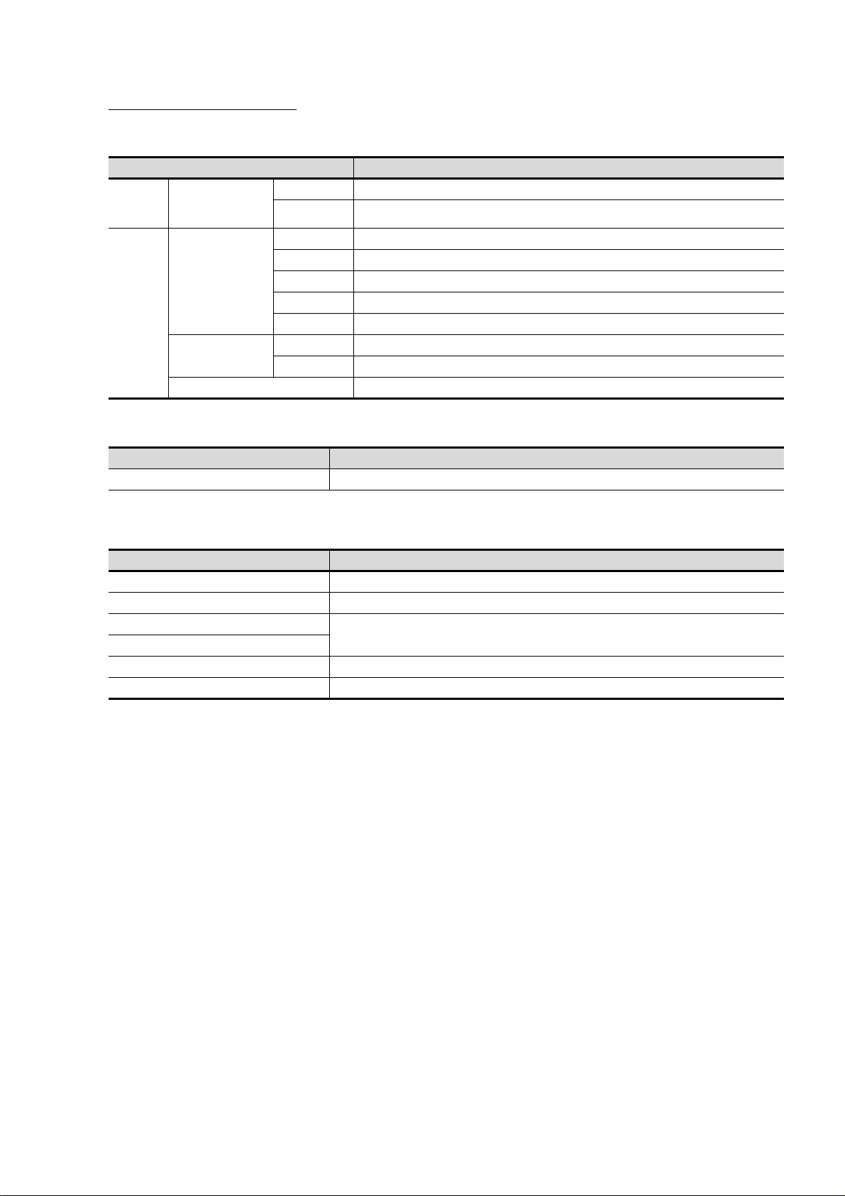
2. SYSTEM CONFIGURATION
Bar code reader
(Commercially available)
Personal computer
(Commercially available)
Printer
*1
(Commercially available)
SD card
2.1 Overall Configuration
The overall configuration of GOT is as follows.
For the connection methods applicable to GS series and cable, refer to the following.
➠ GOT2000 Series Connection Manual For GT Works3 Version1
*1 Only hard copy of the screen can be printed.
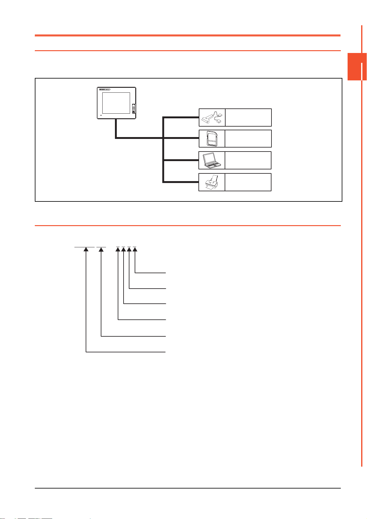
2.2 Component List
(1) Explanation of the GOT model name
2
SYSTEM CONFIGURATION
07 - W
TBDG S 2 1
Power type
Panel color type
Display device type
Resolution
Display color type
GS21 series
D : DC24V
B : Black
T : TFT color
W : 800×480
10 : 10"
07 : 7"
2.1 Overall Configuration
2 - 1
Page 24
2.2.1 GOT
Product name Model Specifications
GS2110-WTBD
GOT
GS2107-WTBD
10" [800 480 dots], TFT color liquid crystal, 65536 colors
24VDC, Memory capacity: 9MB, built-in Ethernet interface
7" [800 480 dots], TFT color liquid crystal, 65536 colors
24VDC, Memory capacity: 9MB, built-in Ethernet interface
2.2.2 Option
■1. Connection cables for MITSUBISHI PLCs (Sold separately)
Cable
length
For connecting FXCPU (MINI DIN 8 pins connector) and GOT
For connecting FXCPU expansion board (MINI DIN 8 pins
connector) and GOT
For connecting FXCPU (D-Sub 25 pins connector) and GOT
For connecting FA-CNV CBL and GOT
For connecting serial communication unit (AJ71QC24(N)-R4)
and GOT
For connecting computer link unit/serial communication unit and
GOT
For connecting FXCPU expansion board (D-Sub 9 pins
connector) and GOT
For connecting FXCPU special adaptor (D-sub 9 pins connector)
and GOT
For connecting FXCPU special adaptor (D-sub 25 pins
connector) and GOT
For connecting computer link unit/serial communication unit and
GOT
RS-422
Cable
RS-232
cable
Product name Model
GT01-C10R4-8P 1m
FXCPU direct
connection cable,
FX expansion board
connection cable
QnA/A/FXCPU direct
connection cable,
computer link
connection cable
Computer link
connection cable
QCPU direct
connection cable
FX expansion board
connection cable,
FX special adaptor
connection cable
FX special adaptor
connection
Computer link
connection cable
GT01-C30R4-8P 3m
GT01-C100R4-8P 10m
GT01-C200R4-8P 20m
GT01-C300R4-8P 30m
GT01-C30R4-25P 3m QnA/A motion controller (A series)
GT01-C100R4-25P 10m
GT01-C200R4-25P 20m
GT01-C300R4-25P 30m
GT09-C30R4-6C 3m
GT09-C100R4-6C 10m
GT09-C200R4-6C 20m
GT09-C300R4-6C 30m
GT01-C30R2-6P 3m For connecting QCPU and GOT
GT01-C30R2-9S 3m
GT01-C30R2-25P 3m
GT09-C30R2-9P 3m
GT09-C30R2-25P 3m
Description
■2. Connection cables for SIEMENS PLCs (Sold separately)]
Product name Model Cable length Description
RS-232 cable GT09-C30R20801-9S 3m For connecting SIEMENS HMI Adapter and GOT
■3. SD card (Sold separately)
Product name Model Description
L1MEM-2GBSD SD memory card 2GB
L1MEM-4GBSD SDHC memory card 4GB
-
Commercially-available SD card
2 - 2
SD card
*1 Some models with the operations checked by our company are usable. For the operation-checked models, refer to "Operation
Check Results of Third Party SD Cards on GT14 Model" (Hime-T-P-0089) separately available, or contact your local distributor.
2.2 Component List
*1
Page 25
■4. Drawing software (Sold separately)
Product name Model Description
SW1DND-GTWK3-J Standard license product
SW1DND-GTWK3-JC
GOT screen creation
software
MELSOFT GT
Works3 Version1
FA integration
engineering software
MELSOFT iQ Works
*3*4
*1 If you need two licenses or more, request the number of licenses. For details, consult your local Mitsubishi representative.
*2 Up to 200 licenses can be registered per site license product. However, this applies only to the same corporation or business
*3 Site license products, multiple-license products, and additional license products can be provided. For details, refer to MELSOFT
*4 This product includes the following software.
SW1DND-GTWK3-JA
SW1DND-GTWK3-JAZ
SW1DND-GTWK3-JV
SW1DND-IQWK-J
SW1DNC-IQWK-J CD-ROM product
facility where the product is purchased.
iQ Works catalog <L(NA)08232ENG>.
• System management software [MELSOFT Navigator]
• PLC engineering software [MELSOFT GX Works2]
• Motion controller engineering software [MELSOFT MT Works2]
• Servo setup software [MELSOFT MR Configurator2]
• GOT screen creation software [MELSOFT GT Works3]
• Robot programming software [MELSOFT RT ToolBox2 mini]
Site license product
Multiple-license product
Additional license product
Standard license product (For upgrading version)
(For upgrading version of user's GT Designer2/
GT Works2 to the latest one)
Standard license product
*2
*1
*1
2
DVD product
SYSTEM CONFIGURATION
■5. PC connection cable (Sold separately)
Product name Model Cable length Description
Project data transfer cable GT09-C30USB-5P 3m
■6. Bar code reader (Sold separately)
Product name Model Description
Bar code -
*1 Some models with the operations checked by our company are usable. For the operation-checked models, contact your local
distributor.
For connecting GOT (USB Mini-B) and personal computer
(USB)
Commercially-available bar code reader
*1
2.2 Component List
2 - 3
Page 26

2 - 4
2.2 Component List
Page 27
3. SPECIFICATIONS
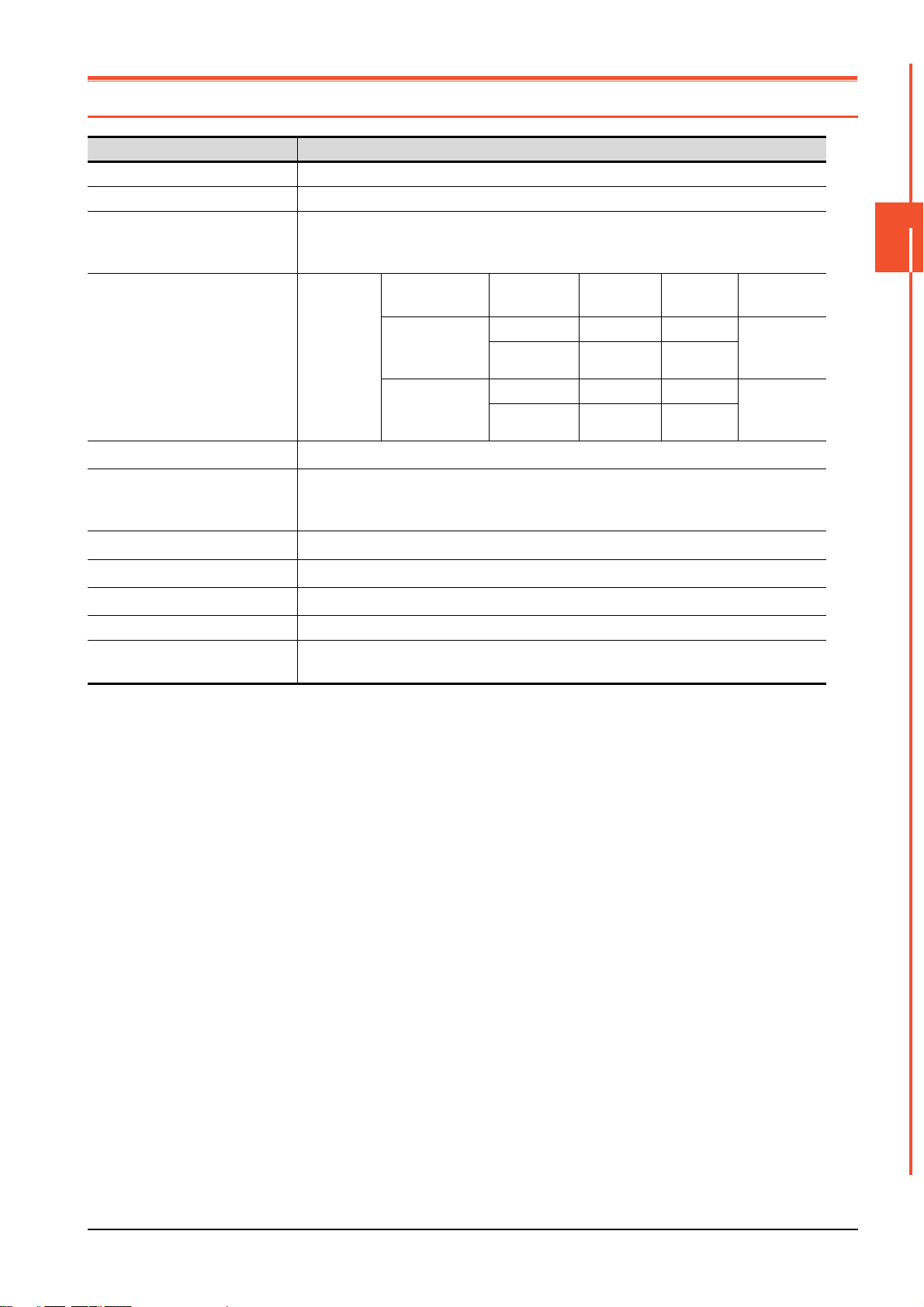
3.1 General Specifications
Item Specifications
Operating ambient temperature 0 to 50°C
Storage ambient temperature -20 to 60°C
10 to 90%RH, non-condensing (The wet bulb temperature is 39°C)
Operating/Storage ambient humidity
Vibration resistance
Shock resistance
Operating atmosphere
Operating altitude
Overvoltage category
Pollution degree
Cooling method Self-cooling
Grounding
*1
*2
*3
*1 Do not use or store the GOT under pressures higher than the atmospheric pressure of altitude 0m (0ft.). Failure to observe this
instruction may cause a malfunction. When the air inside the control panel is purged by pressurization, the surface sheet may be
lifted by high pressure. As a result, the touch panel may be difficult to press, and the sheet may be peeled off.
*2 This indicates the section of the power supply to which the equipment is assumed to be connected between the public electrical
power distribution network and the machinery within the premises. Category II applies to equipment for which electrical power is
supplied from fixed facilities. The surge voltage withstand level for up to the raged voltage of 300V is 2500V.
*3 This index indicates the degree to which conductive pollution is generated in the environment where the equipment is used. In
pollution degree 2, only non-conductive pollution occurs but temporary conductivity may be produced due to condensation.
When the ambient temperature exceeds 40°C, maintain the absolute humidity at 40°C and
90%.
Conforms to
IEC 61131-2
Conforms to IEC 61131-2 (147m/s
Must be free of lamp black, corrosive gas, flammable gas, or excessive amount of electro
conductive dust particles.
Must be no direct sunlight. (Same as for saving)
2000m (6562ft) max.
II or less
2 or less
Class D grounding (100Ω or less), To be connected to the panel when grounding is not
possible.
Under
intermittent
vibration
Under
continuous
vibration
Frequency Acceleration
5 to 8.4Hz - 3.5mm 10times each
8.4 to 150Hz
5 to 8.4Hz - 1.75mm
8.4 to 150Hz
2
, 3times each in the X, Y, and Z directions)
9.8m/s
4.9m/s
Half
amplitude
2
-
2
-
Sweep Count
in X, Y and Z
directions
-
3
SPECIFICATIONS
3.1 General Specifications
3 - 1
Page 28
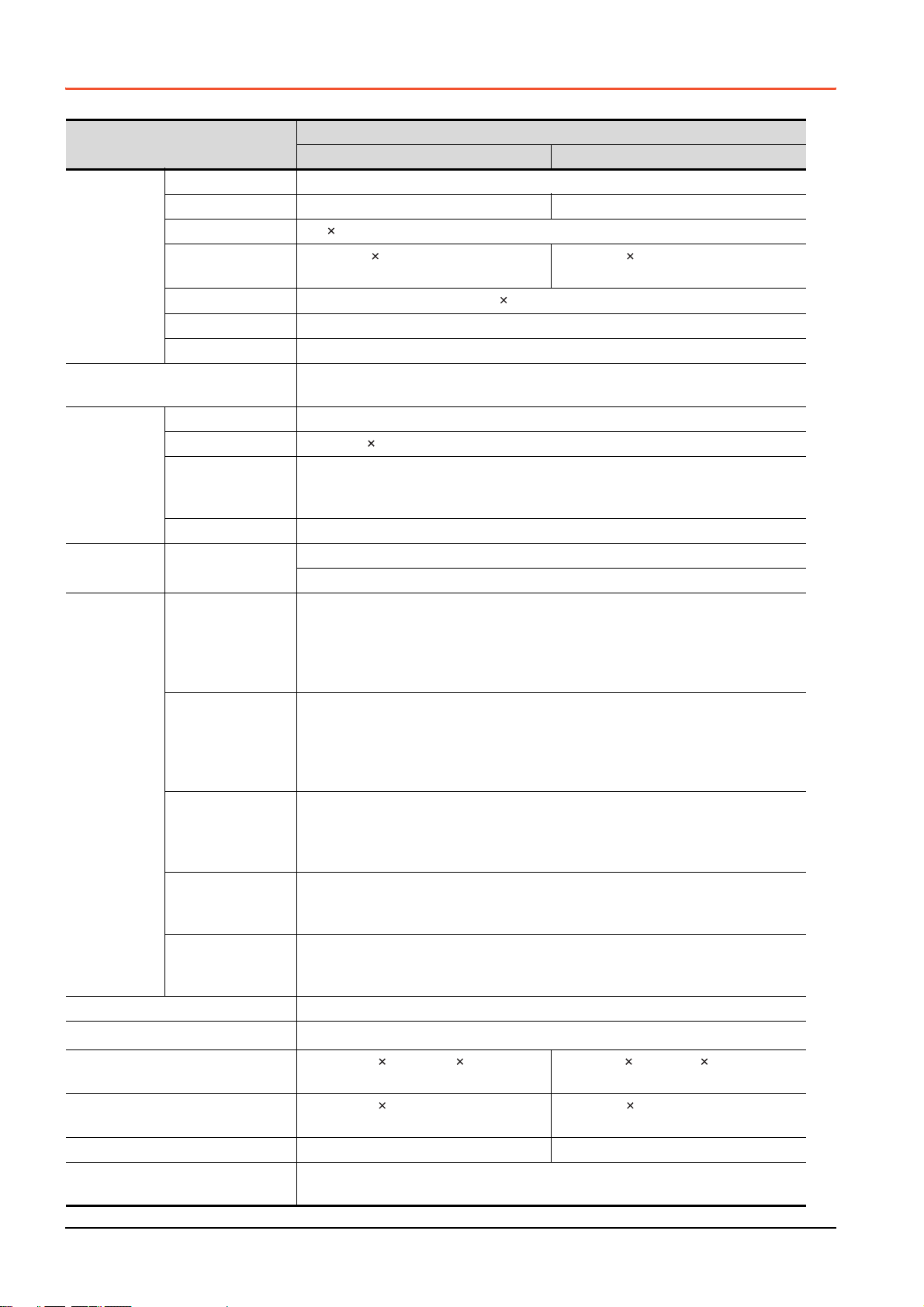
3.2 Performance Specifications
The following shows the performance specifications.
Item
Type TFT color liquid crystal
Screen size 10" 7"
Resolution
Display
*1
section
Backlight
Touch panel
Memory C drive
Built-in
interface
Buzzer output Single tone (LONG/SHORT/OFF adjustable)
Protective structure
External dimensions
Panel cutting dimensions
Weight Approx. 1.3kg (Excluding mounting fixtures) Approx. 0.9kg (Excluding mounting fixtures)
Compatible software package
(Version of GT Designer3)
Display size
Display character
Display color 65536 colors
Brightness 32-level adjustment
Type Analog-resistive film type
Key size
Number of points
*2
touched
simultaneously
Life 1 million times (operating force 0.98N max.)
RS-422
RS-232
Ethernet
USB
SD card
*3
800 480 [dots]
W222(8.74) H132.5(5.22) [mm](inch)
(Horizontal format)
16-dot standard font: 50 characters 30 lines (Horizontal format)
LED-type (no replacement required)
Backlight off/screen saving time can be set.
Minimum 2 2 [dots] (per key)
Simultaneous 2-point presses prohibited (Only one point can be touched.)
Flash memory (Internal) (9MB), for storing project data, OS
Life (Number of write times) 100,000times
RS-422, 1ch
Transmission speed: 115200/57600/38400/19200/9600/4800bps
Connector shape: D-sub 9 pins (Female)
Application: For communicating with controllers
Terminating resistor: 330Ω fixed
RS-232, 1ch
Transmission speed: 115200/57600/38400/19200/9600/4800bps
Connector shape: D-sub 9 pins (Male)
Application: For communication with controllers and a bar code reader
For PC connection (Project data read/write, FA transparent function)
Data Transfer method: 100BASE-TX, 10BASE-T, 1ch
Connector shape: RJ-45 (modular jack)
Application: For communication with controllers
For PC connection (Project data read/write, FA transparent function)
USB (Full Speed 12Mbps) 1ch
Connector shape: Mini-B
Application: For PC connection (Project data read/write, FA transparent function)
Conforms to the SD standard, 1ch
Supported memory card: SDHC memory card, SD memory card
Application: Project data read/write, logging data save
IP65F (only the front part of the panel)
W272(10.71) H214(8.43) D56(2.21)
[mm] (inch)
W258(10.16) H200(7.88) [mm] (inch)
(Horizontal format)
Version1.104J or later
GS2110-WTBD GS2107-WTBD
Specifications
W154(6.06) H85.9(3.38) [mm](inch)
(Horizontal format)
W206(8.11) H155(6.11) D50(1.97) [mm]
(inch)
W191(7.52) H137(5.40) [mm](inch)
(Horizontal format)
3 - 2
3.2 Performance Specifications
Page 29

*1 Bright dots (always lit) and dark dots (unlit) may appear on a liquid crystal display panel. It is impossible to completely avoid this
POINT
symptom, as the liquid crystal display comprises of a great number of display elements. Flickers and partial discoloration may be
generated on the liquid crystal display panel due to individual differences of panels. Please note that these phenomena appear
due to its characteristic and are not caused by product defect.
*2 The touch panel is an analog-resistive type. Simultaneous pressing of two or more areas on the touch panel may activate the
switch between those areas. Do not press two or more areas simultaneously on the touch panel.
*3 Note that this does not guarantee all users' operation environment. In addition, the product may not be used in environments
under exposition of oil or chemicals for a long period of time, or in environments filled with oil-mist.
3.3 Power Supply Specifications
Item
Input power supply voltage 24VDC (+10% -15%), ripple voltage 200mV or less
Power consumption 7.6W (317mA/24V) or less 6.5W (271mA/24V) or less
At backlight off 3.8W (158mA/24V) or less 3.8W (158mA/24V) or less
Inrush current 17A or less (6ms, 25°C, at the maximum load)
Permissible instantaneous
power failure time
Noise immunity Conforms to IEC61000-4-4, 2kV (power supply line)
Dielectric withstand voltage 350VAC for 1 minute (across power supply terminals and earth)
Insulation resistance 500VDC across power terminals and earth, 10 MΩ or more by an insulation resistance tester
Within 5ms
POINT
POINT
GS2110-WTBD GS2107-WTBD
Operation at momentary power failure
The GOT continues to operate even upon 5ms or shorter instantaneous power failure.
The GOT stops operating if there is extended power failure or voltage drop, while it automatically
resumes operation as soon as the power is restored.
Specifications
3
SPECIFICATIONS
3.3 Power Supply Specifications
3 - 3
Page 30
3.4 GOT Connector Specifications
D-Sub 9pin male
GOT main part connector
see from the front
15
69
D-Sub 9pin female
GOT main part connector
see from the front
51
96
The following shows the specifications of connectors for the GOT.
Refer to this section for creating a connection cable by the user.
3.4.1 RS-232 interface
The following shows the connector for the RS-232 interface of the GOT. For the connection cable connector of the GOT
side, use a connector and a connector cover which can be connected to the GOT connector.
■1. Connector specifications
GOT Connector type Connector model Manufacturer
GS series
■2. Connector pin arrangement
D-sub 9 pins (Male)
Inch screw type
17LE-23090-27(D3CC) DDK Ltd.
3.4.2 RS-422 interface
The following shows the connector for the RS-422 interface of the GOT.
For the connection cable connector of the GOT side, use a connector and a connector cover which can be connected to the
GOT connector.
■1. Connector model
GOT Connector type Connector model Manufacturer
GS series
■2. Connector pin arrangement
D-sub 9 pins (Female)
M2.6 mm screw type
17LE-13090-27(D3AC) DDK Ltd.
3 - 4
3.4 GOT Connector Specifications
Page 31

4. PART NAME
4.1 Front Panel
(1)(2)
No. Name Specifications
(1) Display section Displays the utility screen and the user creation screen.
(2) Touch panel For operating the touch switches in the utility screen and the user creation screen
4
PART NAME
4.1 Front Panel
4 - 1
Page 32

4.2 Back Panel
GS2110-WTBD
(6) (10)
(7)
(8)
(4)
(2)(1)(3)(9) (5)
GS2107-WTBD
(6) (7) (8)
(10)
(4)
(1)(3)(9)
No. Name Specifications
(1) RS-232 interface
(2) RS-422 interface For communicating with controller (PLC, microcomputer board, etc) (D-sub 9-pin female)
(3) Ethernet interface For Ethernet communication with controller (PLC, microcomputer board, etc) (RJ-45 connector)
(4) USB interface USB interface (host) for data transfer and saving
Hole for preventing the USB
(5)
cable from unplugging
(6) Rating plate (nameplate)
(7) SD card interface Interface for mounting an SD card to the GOT
(8) SD card access LED ON: SD card is accessed, OFF: SD card is not accessed
(9) Power terminal Power terminal and FG terminal (for power supply (24VDC) to GOT and grounding)
Ethernet communication
(10)
status LED
For communicating with controller (PLC, microcomputer board, RFID, etc) or personal computer
(OS installation, project data download, FA transparent) (D-sub 9-pin male)
Hole for preventing the USB cable from unplugging with a banding band
Model name, current consumption, production number, hardware version, and Boot OS version are
described.
SD RD: Green light while data are being sent or received, 100M: Green light when the transmission
speed is 100Mbps
(5)(2)
4 - 2
4.2 Back Panel
Page 33

4.3 Bottom
GS2110-WTBD
(1)
GS2107-WTBD
(1)
No. Name Specifications
Hole for unit installation
(1)
fittings
Hole for the inserting installation fittings (accessory) during the GOT installation to the panel
(4 holes at top and bottom)
4
PART NAME
4.3 Bottom
4 - 3
Page 34

4 - 4
4.3 Bottom
Page 35

5. EMC DIRECTIVE
5.1 Overview
For the products sold in European countries, the conformance to the EMC Directive, which is one of the European
Directives, has been a legal obligation since 1996.
Manufacturers, who recognize that their products comply with the EMC Directive must declare that their products comply
with the Directives and put a CE mark on the products.
■1. Sales representative in Europe
The sales representative in Europe is as shown below.
Company name: Mitsubishi Electric Europe BV
Address: Mitsubishi-Electric-Platz 1, 40882 Ratingen, Germany
5.1.1 Conforming standards in the EMC Directive
The GOT complies with the following standards in the EMC Directive.
Applied
standard
EN61131-2
: 2007
Test standard Test details Standard value
CISPR16-2-3
Radiated noise
IEC61000-4-2
Electrostatic immunity
IEC61000-4-3
Radiated electromagnetic
field, amplitude modulation
IEC61000-4-4
Fast transient burst noise
IEC61000-4-5
Surge immunity
IEC61000-4-6
Conducted RF immunity
IEC61000-4-8
Power supply frequency
magnetic field immunity
*1 The GOT is an open type device (designed to be integrated in equipment).
*2 QP: Quasi-peak value, Mean: Average value
*3 This test item is conducted in the following conditions.
*1
*1
*1
Make sure to install the GOT on a control panel.
This test item is conducted in the condition where the GOT is installed on a control panel and combined with the MITSUBISHI
PLC.
• 30 MHz to 230 MHz
QP: 40 dBμV/m (measured at 10 m)
• 230MHz to 1000MHz
QP: 47 dBμV/m (measured at 10 m)
Test for measuring electromagnetic
emissions from the product
Immunity test in which static electricity
is applied to the cabinet of the
equipment
Immunity test in which an electric field
is applied to the product
*1
Immunity test in which burst noise is
applied to the power cables and the
*1
signal lines
Immunity test in which lightening surge
is applied to the product
Immunity test in which a noise
inducted on the power cable and the
*1
signal lines is applied
Test for checking normal operations
under the circumstance exposed to the
ferromagnetic field noise of the power
supply frequency (50/60 Hz)
• 30 MHz to 230 MHz
QP: 30 dBμV/m (measured at 30 m)
• 230 MHz to 1000 MHz
QP: 37 dBμV/m (measured at 30 m)
• Contact discharge: ±4 kV
• Aerial discharge: ±8 kV
80 MHz to 1000 MHz: 10 V/m
1.4 GHz to 2 GHz: 3 V/m
2.0 GHz to 2.7 GHz: 1 V/m
(80% amplitude modulation at 1 kHz)
Power cable: 1 kV
Digital I/O: 1 kV
Analog I/O: 1 kV
Signal cable: 1 kV
• AC power type
Power cable (between cable and ground): ±2
kV
Power cable (between cables): ±1 kV
Data communication port: ±1 kV
• DC power type
Power cable (between cable and ground):
±0.5 kV
Power cable (between cables): ±0.5 kV
Data communication port: ±1 kV
Power cable: 10 V
Data communication port: 10 V
30 A/m
*2*3
*2*3
5
EMC DIRECTIVE
5.1 Overview
5 - 1
Page 36

5.2 EMC Directive Requirements
The EMC Directive requires the following.
• Strong electromagnetic waves are not emitted to the outside.: Emission (Electromagnetic interference)
• The product is not affected by the electromagnetic waves from the outside.: Immunity (Electromagnetic sensitivity)
To comply with the EMC Directive, this section explains the precautions for configuring equipment integrating the GOT.
The data described herein are produced with our best, based on the regulation requirements and standards obtained by
Mitsubishi. However, the data do not guarantee that the whole equipment produced according to the data comply with the
above directive.
The manufacturer of the equipment must determine the method to comply with the EMC Directive and conformance to the
directive.
5.2.1 Installing the GOT on the control panel
The GOT is an open type device (designed to be integrated in equipment).
Make sure to install the GOT in a control panel.
This restriction ensures safety and also has a large effect of suppressing noise generated from the GOT by using the control
panel.
■1. Control panel
• The control panel must be conductive.
• When fixing a top or bottom plate of the control panel with bolts, do not coat the plate and bolt surfaces so that they
contact each other.
Connect the door and the box using a thick grounding cable to ensure the low impedance under high frequency.
• To ensure electric conductivity in the large area as much as possible between an inner plate and the control panel,
do not coat the fixing bolt area of the inner plate and the control panel.
• Ground the control panel using a thick grounding cable to ensure the low impedance under high frequency.
• The diameter of cable holes on the control panel must be 10 cm or less.
If the diameter of the hole is 10 cm or more, radio waves may leak.
To reduce the chance of radio waves leaking out, ensure that the space between the control panel and its door is as
small as possible.
Pasting the following EMI gasket directly on the painted surface seals the space, reducing the leak of electric waves.
Manufacturer Series name Contact
KITAGAWA INDUSTRIES CO., LTD. RFSG series (Recommended Product) 0587-34-3651
Our test has been carried out on a panel having the damping characteristics of 37 dB max. and 30 dB mean (measured
by 3m method with 30 to 300 MHz).
■2. Connection of power and ground cables
Ground the GOT and connect power supply cables as shown below.
(1) Wiring the ground cable
Provide a ground point near the GOT.
Ground the frame ground terminal (FG terminal) of the GOT with the thickest and shortest cable as possible.
(2) Ground cable length
The ground cable length must be 30 cm or shorter.
The FG terminals pass the noise generated in the PLC system to the ground.
Therefore, ensure an impedance as low as possible.
Since the ground cables relieve the noise, the cables themselves carry a large noise.
Thus, short wiring prevents the cable from acting as an antenna.
(A long conductor is an antenna radiating noise more efficiently.)
(3) Treatment of the power cable and the ground cable
Twist the ground cable led from the ground point with the power cable.
Twisting with the ground cable relieves more noise from the power cable to the ground.
When a noise filter is installed to the power cable, twisting the power cable and the ground cable may not be
required.
5 - 2
5.2 EMC Directive Requirements
Page 37

5.2.2 Installing a noise filter (power supply line filter)
Input side
(power supply side)
Output side
(device side)
Filter
Wire the input and output cables separately.
Filter
Input side
(power supply side)
Induction
Output side
(device side)
Bundling the input and output cables inducts noise.
Bundling
A noise filter is a part to effectively reduce conducted noise.
Except some models, installation of a noise filter to the power supply lines is not necessary. However, installing the noise
filter can reduce conducted noise.
The noise filter is effective to reduce conducted noise in the band of 10 MHz or less.
Use a noise filter equivalent to the following noise filters (double π-type filters).
Model Manufacturer Rated current Rated voltage
FN343-3/05 SCHAFFNER 3A
250VFN660-6/06 SCHAFFNER 6A
RSHN-2003 TDK 3A
■1. Precautions
The following shows the precautions for installing a noise filter.
(1) Prohibition of bundling cables
Do not bundle the input and output cables of the noise filter.
Bundling the cables inducts the noise from the output-side cable into the input-side cable where noise has been
eliminated by the noise filter.
5
(2) Grounding the noise filter
Connect the ground terminal of the noise filter to the control panel with a short cable as much as possible
(approximately 10 cm).
EMC DIRECTIVE
5.2 EMC Directive Requirements
5 - 3
Page 38

5.2.3 System configuration
POINTPOINTPOINT
■1. GOT
Use the following GOTs having a CE mark on the rating plate.
The following models are compliant with the EMC Directive at factory shipment.
When any GOT other than the following does not comply with the EMC Directive.
Product name Model
GS2110 GS2110-WTBD
GS2107 GS2107-WTBD
■2. Connection type
The following table lists the connection types compliant with the EMC Directive.
○: Compliant with EMC Directive, ×: Not compliant with EMC Directive
Connection type
Ethernet connection ○
Direct CPU connection ○
Computer link connection ○
Other connections
(Connection with non-Mitsubishi PLC, inverter, servo amplifier)
*1 For the details of each connection type, refer to the following manual.
➠ GOT2000 Series Connection Manual (GT Works3 Version1) for the controller used
*2 When connecting the GOT to other controllers such as a non-Mitsubishi PLC, fabricate connection cables and configure the
system following the EMC Directive specifications.
➠ ■4. Non-Mitsubishi PLC, inverter, and servo amplifier connections
*1
GS21
*2
○
Connected devices
When connecting the GOT to a non-Mitsubishi PLC, refer to the manual about the EMC Directive
compliance of the connected device (such as a PLC and a microcomputer).
5.2.4 Connection of power cables and ground cables
Carry out wiring and connect the power and ground cables according to the following instruction.
By the different wiring or connection method, the system may not comply with EMC Directive.
■1. Wiring method
For connection of power cables and ground cables, refer to the following.
Ground the frame ground terminal (FG terminal) of the GOT with the thickest and shortest cable as possible.
➠ 7.2 Wiring Inside and Outside the Panel
5 - 4
5.2 EMC Directive Requirements
Page 39

5.2.5 Fabricating a connection cable
PLC side
GOT s ide
230 or less 40 40 400 or less
(9.06)
(1.57) (1.57)
(9.06)
Unit: mm (inch)
Ferrite core
(ZCAT3035-1330)
Finishing of wearing
120 or less
(4.72)
120
or less
(4.72)
100 or less
Ferrite core
(ZCAT3035-1330)
100 or less
(3.94)
230 or less 40 40
(9.06) (1.58) (1.58)
230 or less
(9.06)
(3.94)
GOT side
PLC CPU side
Unit: mm (inch)
Fabricate the cables used for the GOT by the methods as shown in this section.
The fabrication requires a ferrite core, cable clamp, and cable shielding materials.
The following products have passed the Mitsubishi EMC Directive compliance test.
• ZCAT3035-1330 ferrite core (TDK Corporation)
• AD75CK-type cable clamp (Mitsubishi Electric Corporation)
■1. Ethernet connection
(1) Ethernet cable
Strip off the sheath at both ends of the cable as shown in the figure below to expose braided shield for grounding.
The braided shield sections are used for grounding with a cable clamp.
➠ 5.2.6 Grounding a cable
• Connecting to the Ethernet interface of the GOT
Ferrite core
(ZCAT3035-1330)
GOT side
5
Personal computer side
120
or less
(4.72)
230or less 40 40 400or less
(9.06)
(1.57) (1.57)
■2. Direct CPU connection
(1) RS-232 cable and RS-422 cable
Install a ferrite core to the cable in the positions as shown in the figure below.
■3. Computer link connection
(1) RS-232 cable and RS-422 cable
Strip off the sheath at both ends of the cable as shown in the figure below to expose braided shield sections for
grounding.The braided shield sections are used for grounding with a cable clamp.
➠ 5.2.6 Grounding a cable
(9.06)
120
or less
(4.72)
Unit: mm (inch)
EMC DIRECTIVE
5.2 EMC Directive Requirements
5 - 5
Page 40
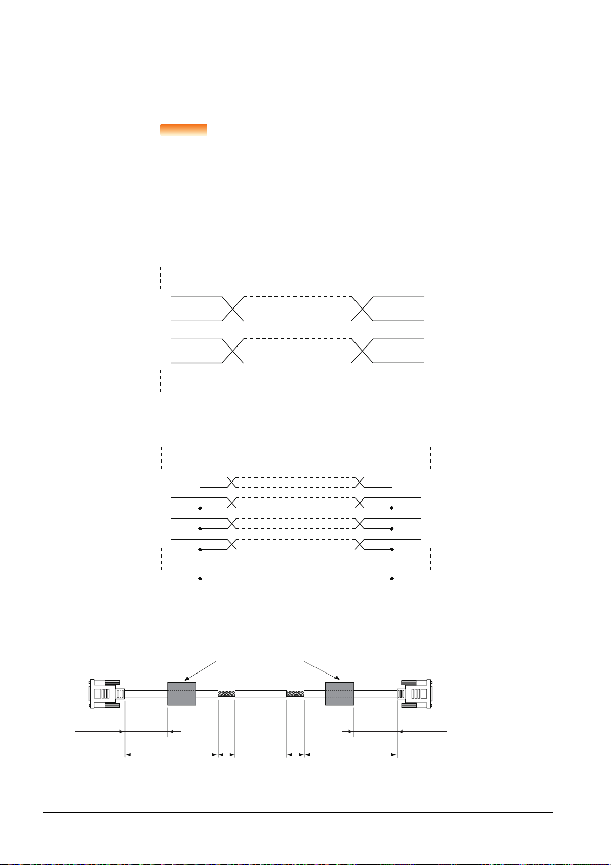
■4. Non-Mitsubishi PLC, inverter, and servo amplifier connections
POINTPOINTPOINT
SDA
RDA
RDB
SDB
RDA
RDB
SDA
SDB
RD
RD
SD
SD
DTR
DTR
DSR
DSR
SG
SG
100 or less
Ferrite core
(ZCAT3035-1330)
100 or less
(3.94)
230 or less 40 40
(9.06) (1.58) (1.58)
230 or less
(9.06)
(3.94)
GOT side
PLC CPU side
Unit: mm (inch)
Create the cables (RS-232 cable, RS-422/485 cable) for connecting the GOT and a controller by yourself.
For how to create a cable, refer to the following.
➠ GOT2000 Series Connection Manual For GT Works3 Version1
Treatment of the RS-232 cable and RS-422/485 cable
When the GOT is connected to a controller, configure the system according to the EMC Directive
specifications for the controller.
The following shows the recommended instructions to comply with the EMC Directive.
However, the manufacturer of the equipment must determine the method to comply with the EMC
Directive and conformance to the directive.
(1) RS-422/485 cable
• When connecting each signal wire (except SG and FG wires), twist two signal wires as
shown below.
• Connect two or more SG wires.
(2) RS-232 cable
• Twist each signal wire (except SG and FG wires) with the SG wire.
• Install a ferrite core to the cable in the positions as shown in the figure below.
• Strip off the sheath at the both ends of the cable as shown in the figure below to expose
braided shield for grounding.
The braided shield sections are used for grounding with a cable clamp.
5 - 6
5.2 EMC Directive Requirements
Page 41

5.2.6 Grounding a cable
Braided shield
Cable clamps
For the attachment details of
cable clamps, refer to
AD75CK-type Cable Clamping
Instruction Manual
<IB-68682>.
■1. Grounding method
Ground the cable and ground cable to the control panel where the GOT and the PLC are installed.
Ground the braided shield section of the cable to the control panel with the cable clamp (AD75CK).
To ground a bus connection cable, ground the braided cable for grounding to the control panel by tightening a screw.
■2. Precautions
Do not arrange the cable clamp close to the other cables that are not clamped.
The noise from the control panel may enter the cable clamp and adversely affect the GOT.
5
EMC DIRECTIVE
5.2 EMC Directive Requirements
5 - 7
Page 42

5 - 8
5.2 EMC Directive Requirements
Page 43

6. INSTALLATION
POINT
MOUNTING PRECAUTIONS
• Be sure to shut off all phases of the external power supply used by the system before mounting or removing the GOT
main unit to/from the controller.
Not doing so can cause the unit to fail or malfunction.
MOUNTING PRECAUTIONS
• Use the GOT in the environment that satisfies the general specifications described in this manual.
Not doing so can cause an electric shock, fire, malfunction or product damage or deterioration.
• Never drop cutting chips and electric wire chips into the ventilation window of the GOT when you drill screw holes or
perform wiring.
Otherwise, fire, failure or malfunction may be caused.
• Connect connection cables securely to the specified connectors while the power is turned OFF.
Imperfect connection may cause malfunction or failure.
• Operate and store the GOT in environments without direct sunlight, dust, lamp black, conductive dust, corrosive gas,
combustible gas, high temperature, condensation, wind, rain, vibrations and impacts.
Electric shock, fire, malfunction, product damage or deterioration can be caused.
• Tighten the mounting screws within the specified torque range.
Undertightening can cause the GOT to drop, short circuit or malfunction. In addition, undertightening can disable
waterproof or oil proof effect.
Overtightening can cause a drop, short circuit or malfunction due to the damage of the screws or the GOT. In addition,
the waterproof effect and oilproof effect may not be available due to the "distortion" of GOT or panel.
WARNING
CAUTION
6
6.1 Control Panel Inside Dimensions for Mounting GOT
Mount the GOT onto the control panel while considering the following control panel inside dimensions.
(If the vertical format is selected, the dimension, which is rotated 90 degrees clockwise looking from the display section side,
is required.)
POINT
POINT
Applicable cable
Some cables may need to be longer than the specified dimensions when connecting to the GOT.
Therefore, consider the connector dimensions and bending radius of the cable as well for
installation.
INSTALLATION
30(1.18)
Unit: mm(inch)
6.1 Control Panel Inside Dimensions for Mounting GOT
6 - 1
Page 44
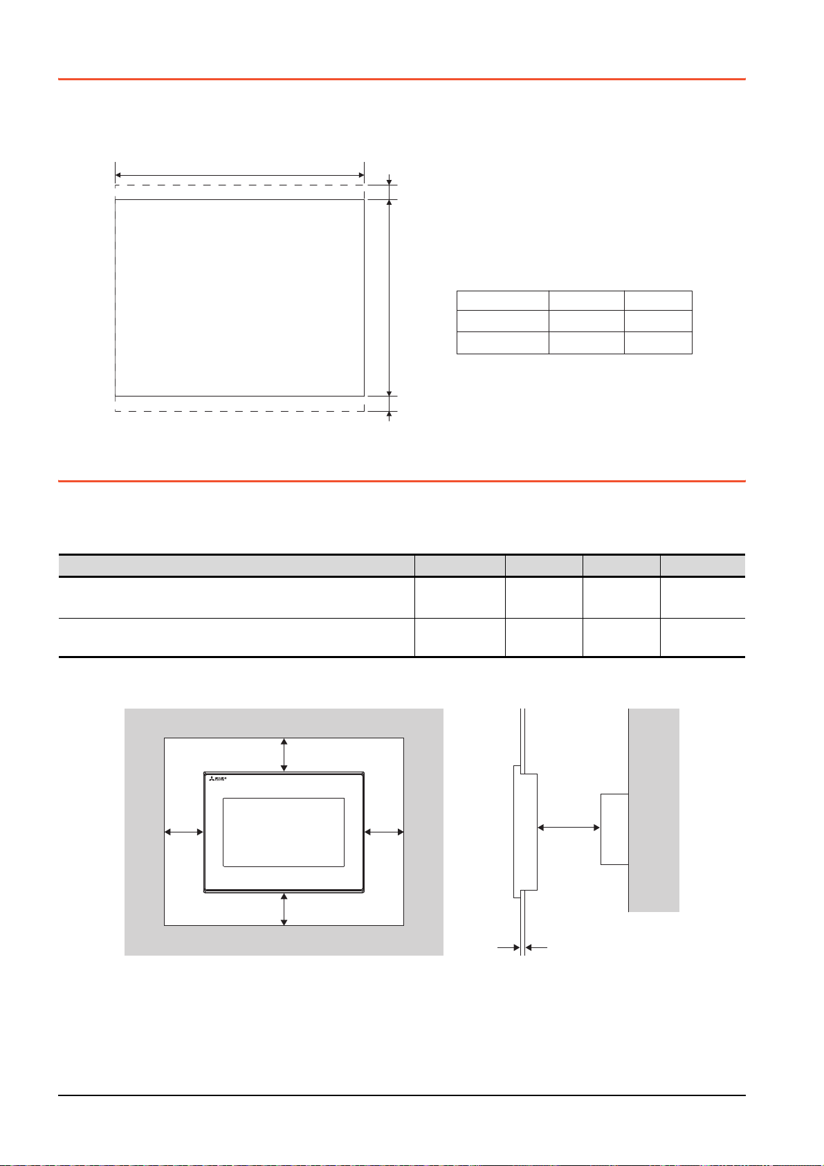
6.2 Panel Cutting Dimensions
A
+2
-0
10 (0.4") or more
10 (0.4") or more
Unit: mm (inch)
Panel thickness: 1.6 to 4mm
(0.06" to 0.15")
B
+2
-0
GS2110-WTBD
GS2107-WTBD 191 (7.52") 137 (5.4")
258 (10.16") 200 (7.88")
A
B
Item
BA
CD
E
Panel thickness: 1.6 to 4mm
Cut holes in the following dimensions on the panel.
Ensure 10mm of space in upper and lower parts of the panel for mounting fixtures.
• Horizontal format (If the vertical format is selected, the dimension must be rotated 90 degrees.)
6.3 Mounting Position
When mounting the GOT, the following clearances must be maintained from other structures and devices.
• Horizontal format (If the vertical format is selected, the dimension, which is rotated 90 degrees clockwise looking from the
display section side, is required.)
Installation Environment A, D [mm] (inch) B [mm] (inch) C [mm] (inch) E [mm] (inch)
In the presence of radiated-noise or heat-generating equipment nearby
In the absence of radiated-noise or heat-generating equipment nearby
*1 Vertical Format....50mm (1.97") or more
*2 Vertical Format....80mm (3.14") or more
50mm (1.97")
or more
20mm (0.79") or
more
80mm (3.14")
or more
20mm (0.79")
or more
*1
50mm (1.97")
*2
or more
20mm (0.79")
or more
100mm (3.94")
or more
20mm (0.79")
or more
6 - 2
6.2 Panel Cutting Dimensions
Page 45

6.4 Control Panel Temperature and Mounting Angle
GOT
back panel
GOT
display
section
Control panel,
etc.
105°
60°
GOT
back panel
GOT
display
section
Control panel,
etc.
105°
60°
When mounting the main unit to a control panel or similar fixture, set the GOT display section as shown below.
■1. Horizontal installation
When the temperature inside the control panel is 40 to 50°C, the mounting angle should be in the range from 60 to 105
degrees.
The GOT will have a longer lifetime if used within the mounting angles shown above.
Ideally, the temperature inside the control panel should not exceed 0 to 40°C.
■2. Vertical installation
When the temperature inside the control panel is 40 to 50°C, the mounting angle should be in the range from 60 to 105
degrees.
6
The GOT will have a longer lifetime if used within the mounting angles shown above.
Ideally, the temperature inside the control panel should not exceed 0 to 40°C.
INSTALLATION
6.4 Control Panel Temperature and Mounting Angle
6 - 3
Page 46

6.5 Installation Procedure
POINTPOINTPOINT
Mounting hole
Mounting
fitting
Mounting
screw
The GOT is designed to be embedded into a panel. Mount the GOT by following the procedure below.
Refer to "6.2 Panel Cutting Dimensions" for the panel cutting dimensions.
In addition, the thickness of the installation panel face must be 1.6 to 4mm.
Step 1. Inserting into the panel face
Insert the GOT from the front side of the panel.
Step 2. Fixing the GOT
Engage the hook of the mounting fixture (accessory) to
the unit fixing hole of the GOT and fix them by tightening
the mounting screws (accessory) in the torque range of
0.36 to 0.48N
·m.
Step 3. A protection film is attached on the display section of
GOT prior to shipment. Remove the film when the
installation is completed.
Check that the packing is firmly attached with the GOT.
If the packing is loose, attach the packing to the GOT securely.
6 - 4
6.5 Installation Procedure
Page 47

POINT
POINT
POINT
Cautions on installation
(1) Tightening the mounting screw
Tighten the mounting screw within the specified torque.
Under tightening can cause the GOT to drop. In addition, undertightening can disable
waterproof or oil proof effect.
Failure to do so may damage the unit, or distort the panel and make a surface waviness on
the display area, leading to deterioration of the visibility or incorrect input from the touch
panel. In addition, undertightening can disable waterproof or oil proof effect.
• Specified torque range: 0.36 to 0.48N
(2) Installation panel surface
Make sure that the panel surface is free from warpage, flaws and irregularities. Warpage,
flaws and irregularities may disable the waterproof effect.
Select proper panel thickness under consideration of the panel strength.
(For example, the panel strength may be insufficient depending on the panel material and
dimensions even if the panel thickness is acceptable.
Insufficient panel strength may cause warpage depending on the installation positions of the
GOT and other equipment.)
·m
6
INSTALLATION
6.5 Installation Procedure
6 - 5
Page 48

6 - 6
6.5 Installation Procedure
Page 49

7. WIRING
POINT
WIRING PRECAUTIONS
• Be sure to shut off all phases of the external power supply used by the system before wiring.
Failure to do so may result in an electric shock, product damage or malfunctions.
• Please make sure to ground FG terminal of the GOT power supply section by applying 100Ω or less which is used
exclusively for the GOT.
Not doing so may cause an electric shock or malfunction.
• Correctly wire the GOT power supply section after confirming the rated voltage and terminal arrangement of the
product.
Not doing so can cause a fire or failure.
• Tighten the terminal screws of the GOT power supply section in the specified torque range.
Undertightening can cause a short circuit or malfunction.
Overtightening can cause a short circuit or malfunction due to the damage of the screws or the GOT.
• Exercise care to avoid foreign matter such as chips and wire offcuts entering the GOT.
Not doing so can cause a fire, failure or malfunction.
WIRING PRECAUTIONS
• Plug the communication cable into the connector to be connected, and tighten the mounting screws and the terminal
screws in the specified torque range.
Undertightening can cause a short circuit or malfunction.
Overtightening can cause a short circuit or malfunction due to the damage of the screws or unit.
This chapter describes the wiring to the GOT power supply section.
For the connection with a PLC, refer to the following.
WARNING
CAUTION
➠ GOT2000 Series Connection Manual For GT Works3 Version1
For the dimensional drawing of connection cables, refer to the following.
➠ Appendix.1 External Dimensions
7
WIRING
POINT
POINT
General preventive measures against noise
There are two kinds of noises: Radiated noise that is transmitted into the air and Conductive
noise that is directly transmitted along connected lines. Countermeasures must be taken
considering both kinds of noises and referring to the following 3 points.
(1) Protecting against noise
(a) Keep signal lines away from noise sources such as a power cable or a high-power drive
circuit.
(b) Shield the signal lines.
(2) Reducing generated noise
(a) Use a noise filter, etc. to reduce the level of the noise generated due to a source such as
a high-power motor drive circuit.
(b) Attach surge killers to the terminals on the no fuse breakers (NFB), electromagnetic
contactors, relays, solenoid valves, and generators to suppress noise interference.
(3) Releasing noise to the ground
(a) Make sure to connect the ground cable to the ground.
(b) Use a short and thick cable to lower its ground resistance.
(c) Ground the power system and the control system separately.
7 - 1
Page 50

7.1 Power Supply Wiring
8 to 12mm
14 to 18mm
2.8 to 4.2mm
Te rm i na l
contact
section
Insulation sleeve
Connect the power supply to the power terminals on the back panel of the GOT.
Use a specified size power supply wire to prevent voltage drop, and tighten the terminal screws firmly to a specified torque.
Do not exceed the number of wires that are allowed to be connected.
Secure the wires to prevent stress from being directly applied to the terminal block or wire connections.
7.1.1 Cable types and wire end processing
Process the end of the electrical wire (solid or stranded), or attach a ferrules with plastic sleeve to the wire end.
Terminal screws should be tightened to between 0.3 to 0.5N
connection thus avoiding a malfunction.
When tightening terminal screws, do not exceed the specified torque. Failure to do so may cause equipment failures or
malfunctions.
■1. Electrical wire size
Electrical wire size
Solid wire Stranded wire Ferrules with plastic sleeve
0.5 to 2.5mm
AWG20 to AWG14
2
0.5 to 2.5mm
AWG20 to AWG14
■2. Wire end processing
·m. Terminal screws must be secured to prevent a loose
2
0.5 to 2.5mm
AWG20 to AWG14
2
(1) Connecting the wire directly
(a) Twist the end of the stranded wire. Make sure there are no wire whiskers.
(b) Do not solder the wire end.
(2) Using a ferrules with plastic sleeve to connect the wire
A wire with a too thick of a wire sheath may not fit the insulation sleeve. Refer to the
outline drawing for how to select the proper size wire.
Manufacturer Model Crimper type
AI 0.75-8BU (0.5 to 0.75mm
Phoenix Contact Inc.
AI 1.0-8RD (0.75 to 1.0mm
AI 1.5-8BK (1.0 to 1.5mm
AI 2.5-8BU (1.5 to 2.5mm
■3. Tools
Use a small driver with a straight, untapered blade as shown on the right to tighten
the power terminals.
Manufacturer Model
Phoenix Contact Inc.
SZS 0.6 3.5
Approx. 6mm
2
)
2
)
2
)
2
)
CRIMPFOX UD6
Use a driver
with a flat end
0.6mm 3.5mm
7 - 2
7.1 Power Supply Wiring
Page 51

7.1.2 Wiring example
Class D
grounding
Other
device
GOT
Other
device
GOT
Other
device
GOT
(1) Independent ground
...... Best condition
(2) Shared grounding
...... Good condition
(3) Common grounding
...... Not allowed
Grounding
(100Ω or less)
Grounding
(100Ω or less)
Connect the power supply to the power terminals on the back panel of the GOT.
Tightening torque for the power terminals
0.5 to 0.6N
·m
7.1.3 GOT's ground
■1. Grounding the GOT and other devices
Make sure to carry out the followings for grounding.
• Carry out the independent grounding if possible.
Provide class D (class 3) grounding. (Ground resistance must be 100W or less.)
• If the independent grounding is impossible, carry out the shared grounding as shown in fig.2) below.
2
• Use the cable of 2mm
Set the grounding point closer to the GOT to make the grounding cable short as possible.
or longer for grounding.
7
WIRING
7.1 Power Supply Wiring
7 - 3
Page 52
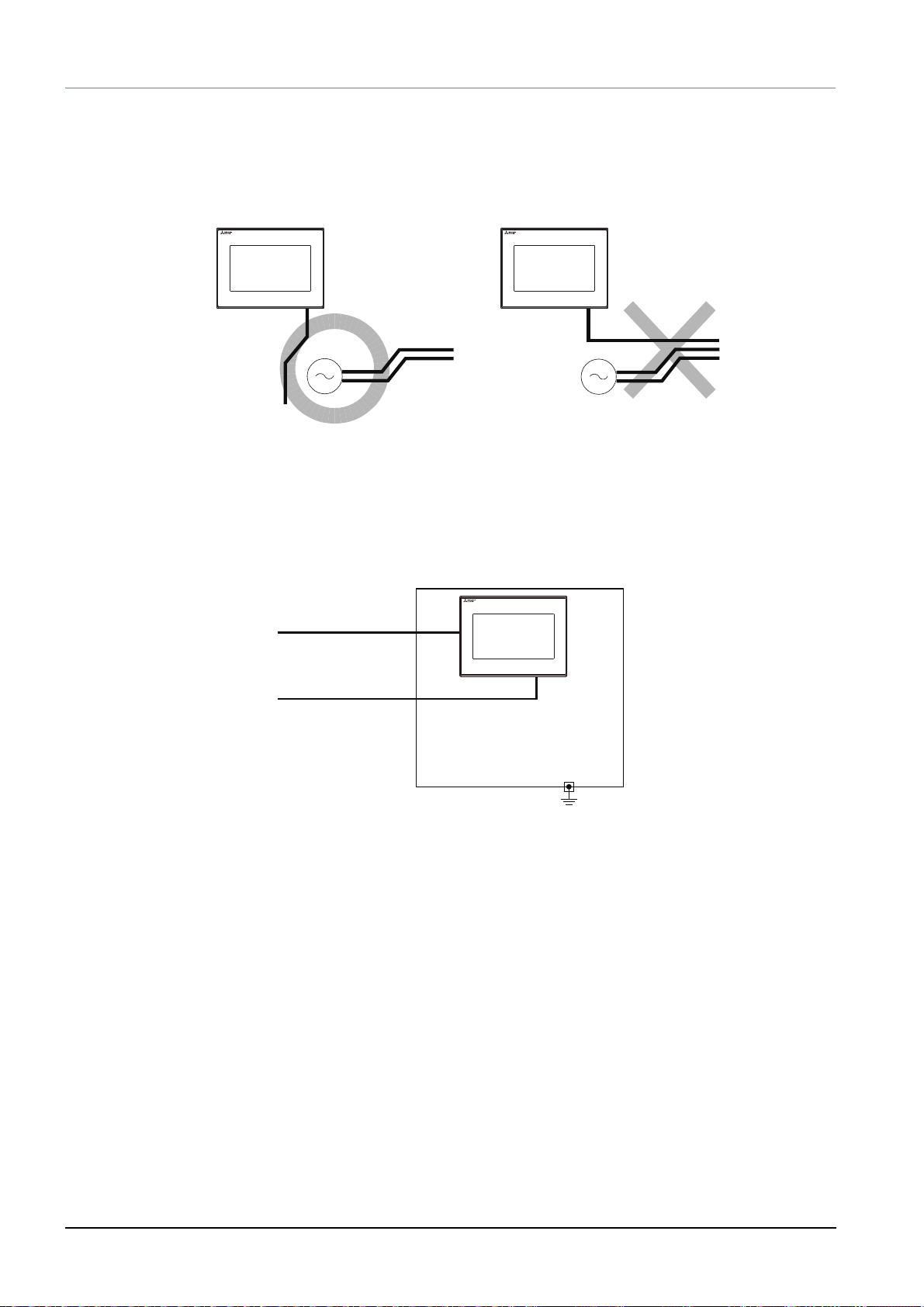
7.1.4 The cause of malfunctions related wiring/Remedy
FG
Power supply
for power equipment
Power supply
for power equipment
Good: Wiring the ground cable away
from the power cable
FG
Bad: Bundling the ground cable and
the power cable
Grounding of the GOT may cause electric potential difference and noise interference, which may result in GOT
malfunctions. These problems may be resolved by taking the following measures.
■1. Wiring path of the GOT's ground cable and power line
Bundling the GOT's ground cable and power line together can cause interference noise, which may result in
malfunctions.
Keeping the GOT's ground cable and power line away from each other will help minimize noise interference.
■2. Connecting the ground cable from the panel that houses control equipment to the panel to
which the GOT is grounded
When running a single ground cable from the panel that houses such piece of control equipment as a sequencer to the
panel to which the GOT is grounded, the ground cable may have to be directly connected to the terminal on the GOT.
Connection cable
FG
Ground cable from
the panel that houses
control equipment
If electric potential difference between the ground points created by it causes malfunctions, lowering the voltage as
shown in Remedy 1 below may solve the problem.
7 - 4
7.1 Power Supply Wiring
Page 53

• Remedy 1 (Refer to the figures Remedy 1-1 and 1-2 below.)
FG
Ground cable from
the panel that houses
control equipment
Connection cable
Panel
grounding
Panel
grounding
Remedy1-1
Use the thickest
cable possible.
FG
Connection cable
Remedy1-2
Ground cable from
the panel that houses
control equipment
Use the thickest
cable possible.
Ground cable from
the panel that houses
control equipment
Connection cable
Remedy2-1
Use the thickest
cable possible.
Ground cable from
the panel that houses
control equipment
Use the thickest
cable possible.
FG
Connection cable
Remedy2-2
FG
Panel
grounding
Panel
grounding
Ferrite core
Ferrite core
If the electric potential difference between the ground cable and the panel that houses the GOT is creating problems,
connect the ground cable to the panel also.
If the wiring method as shown in Remedy 1-1 is not feasible, follow Remedy 1-2.
If taking Remedy 1 worsens noise interference, taking Remedy 2 may alleviate it.
• Remedy 2 (Refer to the figures Remedy 2-1 and 2-2 below.)
Attach a ferrite core to the cable if noise from the GOT panel has adverse effects on the GOT when Remedy 1 is
taken.
Wind the wire around the ferrite core several times (approx. 3times), if a ferrite core is used.
If the wiring method as shown in Remedy 2-1 is not feasible, follow Remedy 2-2.
7
WIRING
7.1 Power Supply Wiring
7 - 5
Page 54

7.2 Wiring Inside and Outside the Panel
NFB
MC
PLC
MC RA RA
Terminal block
Crossing power lines and
communication cables
GOT connection cable
PLC I/O wire
Drive control wire
NFB
MC
PLC
MC RA RA
Terminal block
Uncrossed power lines and
communication cables
GOT connection cable
PLC I/O wire
Drive control wire
Power
cable
Power
cable
7.2.1 Wiring inside
Run power lines, servo amplifier drive wires, and communication cables so that they do not cross each other.
Noise interference that is generated by cables that cross each other may cause malfunctions.
Surge suppressors are an effective way to filter out surge noise that is generated from no fuse breakers (NFB),
electromagnetic contactors (MC), relays (RA), solenoid valves, and induction motors.
Refer to the section to follow for surge killers.
➠ 7.2.3 Attaching surge killers to control equipment
7.2.2 Outside the panel
To pull the power line and communication cable out of the panel, make two pullout holes away from each other and pull the
cables through.
Putting both cables through the same pullout hole will increase noise interference.
Power line
Power line
Connection
cable
Pullout hole Pullout hole
Keep the power line and communication cable inside the duct at least 100mm away from each other.
If that is not possible, the use of a metal separator inside the duct can reduce noise interference.
Power line
Wiring duct
100mm or more
Signal line
Power line
Connection
cable
Separator
Signal line
7 - 6
7.2 Wiring Inside and Outside the Panel
Page 55
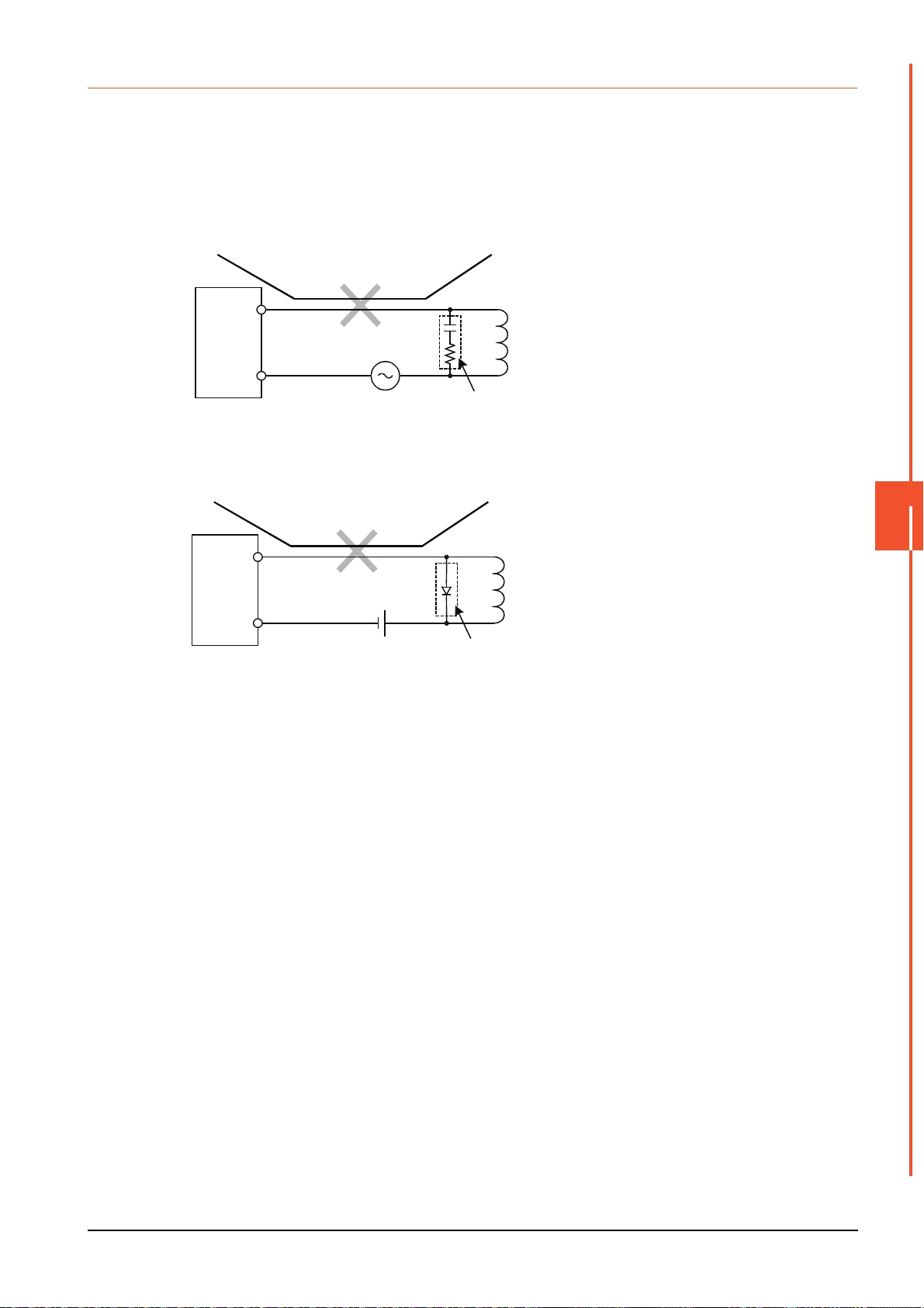
7.2.3 Attaching surge killers to control equipment
Output
AC
C
R
L: Load
Keep the ground cable and
communication cable away
from each other.
Place the surge killer
near the load.
Output equipment
such as PLC output unit
Output
DC
D
L: Load
Keep the ground cable and
communication cable away
from each other.
Place the surge killer
near the load.
Output equipment
such as PLC output unit
If communication errors happen in synch with the on/off signals from certain control equipment (referred to as "load"
hereafter) such as no fuse breakers, electromagnetic contactors, relays, solenoid valves, and induction motors, surge noise
interference is suspected.
If this problem happens, keep the ground cable and communication cable away from the load.
If that is not possible, an installation of a surge killer will help reduce noise interference.
Place the surge killer as close to the load as possible.
Remedy for AC inductive load
Remedy for DC inductive load
7
WIRING
7.2 Wiring Inside and Outside the Panel
7 - 7
Page 56

7 - 8
7.2 Wiring Inside and Outside the Panel
Page 57

8. OPTION
SD card
surface
8.1 SD Card
The SD card is used to transfer the OS or project data and to save the data of the alarm history function.
For details, refer to the following.
➠ 15. CONTROL OF VARIOUS DATA (DATA CONTROL)
8.1.1 Applicable SD card
The following SD cards are applicable for GOT.
Model Specifications
L1MEM-2GBSD SD memory card 2GB
L1MEM-4GBSD SDHC memory card 4GB
NZ1MEM-2GBSD SDHC memory card 2GB
NZ1MEM-4GBSD SDHC memory card 4GB
NZ1MEM-8GBSD SDHC memory card 8GB
NZ1MEM-16GBSD SDHC memory card 16GB
-
*1 Some models with the operations checked by our company are usable. For the operation-checked models, refer to "Operation
Check Results of Third Party SD Cards on GT14 Model" (Hime-T-P-0089) separately available, or contact your local distributor.
Commercially-available SD card
*1
8.1.2 Installation/removal procedure of SD card
Install/remove the SD card when the power supply of the GOT is OFF or [Access inhibit] is set in the [SD card access]
setting of the GOT.
■1. Installation
Step 1. Touch [Main Menu] [Data] [SD card
access] [Permissions] to set [Access
inhibit].
➠ 15.4 SD Card Access
Check that the SD card access LED turns
off.
When the SD card access LED is off, the
SD card can be installed or removed even
when the GOT is on.
Step 2. Insert a SD card into the SD card interface
with its front side (nameplate side) outside.
8
OPTION
Step 3. Touch [SD card access] [Access inhibit]
to set [Permissions].
Check that the SD card access LED turns
on.
8.1 SD Card
8 - 1
Page 58

■2. Removal
POINTPOINTPOINT
Step 1. Touch [Main Menu] [Data] [SD card
access] [Permissions] to set [Access
inhibit].
➠ 15.4 SD Card Access
Check that the SD card access LED turns
off.
When the SD card access LED is off, the
SD card can be installed or removed even
when the GOT is on.
Step 2. Push the SD card all the way inside and
leave your finger once, then remove the
SD card.
Precautions when removing the SD card
• Do not pull out the SD card or power OFF the GOT while the SD card access LED is lit.
To do so may cause data corruption or malfunction.
• When removing the SD card from the GOT, make sure to support the SD card by hand as it
may pop out.
Failure to do so may cause the SD card to drop from the GOT, resulting in a failure or break.
8 - 2
8.1 SD Card
Page 59

9. UTILITY FUNCTION
Install directly
from GT Designer3
Via a USB interface or
Ethernet interface
GT Designer3
GT Designer3
Writing
package data
2) GT Designer3→SD card→GOT
GOT
GOT
*1
*1
Installing
package data
Installing Boot OS or Package data
When GOT is remote,
install using SD card
easily
Install SD
card to
the GOT
SD card
1) GT Designer3→GOT
Utility is a function, which carries out connection of GOT and controller, screen display and operation method settings,
program/data control and self-check etc.
9.1 Utility Execution
For utility execution, utility has to be displayed by installing Boot OS and package data in the C drive (built in flash memory).
There are following two methods for installing Boot OS and package data.
Refer to the following for the installation which uses GT Designer3.
For the installation methods of package data with an SD card, refer to the following.
➠ GT Designer3 (GOT2000) Help
➠ 18. BootOS and System Application Installation Using Data Storage
UTILITY FUNCTION
9
9.1 Utility Execution
9 - 1
Page 60

9.2 Utility Function List
The items in the following list can be set/operated on the utility screens.
Item Functions overview Reference
Language Switching message languages
Standard I/F Assigning channel number and communication driver to communication interface
GOT IP Address Configuring GOT Ethernet setting
Ethernet communication Displaying the contents of Ethernet setting, changing the host
Comm.
Setting
GOT setup
Security
Setting
Time setting Time setting
Data
Debug
Maintenance
Comm. Monitor Checking the serial communication port communication
Ethernet check Checking the Ethernet communication port communication
Transparent mode
Keyword
Display
Operation
Unique info Setting the GOT ID No.
GOT internal device
monitor
Security level Changing the security level
Operator
Login/Logout
OS information OS information
Alarm info.
Resource
Data
SD card access Setting the access permission of the SD card
SD card format Formatting the SD card
Clear data Clearing the project data and resource data on the GOT
Data copy Transferring the project data or OS to the SD card
Backup/restore
Device monitor
FX list editor Changing parameters and sequence program of FX PLC
FX3U-ENET-ADP Configuring the communication setting for FX3U-ENET-ADP stored in the FXCPU
Touch panel calibration Displaying the screen for cleaning the display
Touch panel check Checking the touch panel operation
Clean Displaying the screen for cleaning the display
Recipe
info.
Logging
info.
Image file Deleting or copying hard copy files
Setting the channel No. to be used for the communication for the FA transparent
function
Setting or deleting sequence program protection key words and canceling
sequence program protection status for the FXCPU connection
Setting the title display period
Setting the screen save time
Adjusting brightness
Setting the buzzer sound
Setting the window move buzzer
Setting the key reaction speed
Touch panel calibration
Setting the utility call keys
Setting the Use/Disuse the GOT internal device monitor of GOT diagnostics
Operator management
Password change
Function setting
Deleting or copying alarm log files
Converting alarm log files in G1A format CSV/TXT format
Converting recipe files in G1P format CSV/TXT format
Converting CSV/TXT format Recipe files in G1P format
Deleting or copying recipe files
Converting logging files in G1L format CSV/TXT format
Deleting or copying logging files
Setting the backup and restoration
Device monitor of PLC, test function, current value change of the buffer memory
and the buffer memory monitor of intelligent module
➠ 10.
➠ 11 .1
➠ 11 .2
➠ 11 .3
➠ 11 .4
➠ 11 .5
➠ 11 .6
➠ 11 .7
➠ 12.1
➠ 12.2
➠ 12.3
➠ 12.4
➠ 13.1
➠ 13.2
➠ 13.3
➠ 14.1
➠ 15.2
➠ 15.3.1
➠ 15.3.2
➠ 15.3.3
➠ 15.3.4
➠ 15.4
➠ 15.5
➠ 15.6
➠ 15.7
➠ 15.8
➠ 16.1
➠ 16.2
➠ 16.3
➠ 17.1
➠ 17.2
➠ 17.3
9 - 2
9.2 Utility Function List
Page 61

9.3 Utility Display
To display setting screens for each utility, the main menu has to be displayed first.
(1) Main menu
The menu items that can be set at the GOT utility are displayed.
Touching a menu item in the main menu will display the setting screen or following selection screen for the item.
(2) System message switch button
This button switches the language used for the utility or system alarms.
When touching the [Language] button, the Select Language screen is displayed.
Step 1. Touch the language button of a desired language and touch the [OK] button to select the language.
Step 2. Touching the [ ] button switches the language on the utility to the selected one.
UTILITY FUNCTION
9
9.3 Utility Display
9 - 3
Page 62

POINTPOINTPOINT
(1) When starting the GOT without selecting any language or the selected language and
the installed fonts are not matched
The following screen will be displayed.
Touching the button of a desired language restarts the GOT and the language is switched to
the selected one.
(2) Selectable languages
The system message switch button is displayed only for the selectable languages.
The selectable languages differ depending on the fonts installed in the GOT.
For the relation between the selectable languages and the fonts, refer to the following.
➠ GT Designer3 (GOT2000) Help
(3) System language switching using the device
The system language can be switched using the system language switching device set with
GT Designer3. For the setting method of the system language switching device, refer to the
following.
➠ GT Designer3 (GOT2000) Help
9 - 4
9.3 Utility Display
Page 63

9.3.1 Display operation of main menu
POINT
Turning on the power
supply of the GOT
Touch [OK] button
The following four types of operation can display the main menu.
(Display the main menu after installing the standard monitor OS from GT Designer3 to the GOT built in flash memory.)
(1) When project data is undownloaded
After the GOT is turned on, a dialog box for notifying of absence of project data is displayed. After the dialog box is
displayed, touch the [OK] button to display the main menu.
(2) When touching utility call key
If you touch the utility call key while user-created screen is displayed, the main menu is displayed.
The utility call key is set in the position on the GOT screen upper left corner at factory shipment.
Horizontal format Vertical format
The utility call key can be set by the GOT utility or GT Designer3.
For the setting method of the utility call key, refer to the following.
*1 The utility function windows appear in the horizontal format, and this format cannot be changed.
➠ 12.2.5 Setting the utility call keys
➠ GT Designer3 (GOT2000) Help
POINT
POINT
(1) Prohibited simultaneous 2-point presses
Do not touch 2 points or more on the GOT screen simultaneously. Touching 2 points or more
simultaneously may activate a part other than the touched point.
(2) Press time of the utility call key
When having set [Press time] of the utility call key setting screen to other than "0 (s)", keep
pressing the touch panel for the period set to [Press time] or more before leaving the finger
from the touch panel.
For utility call key setting, refer to the following.
➠ 12.2.5 Setting the utility call keys
(3) When the utility call key is not set
Even when the utility call key is not set (set to the zero point), you can display the main menu
by performing the following operation.
• Pressing the special function switch set on the user-created screen
UTILITY FUNCTION
9
9.3 Utility Display
9 - 5
Page 64
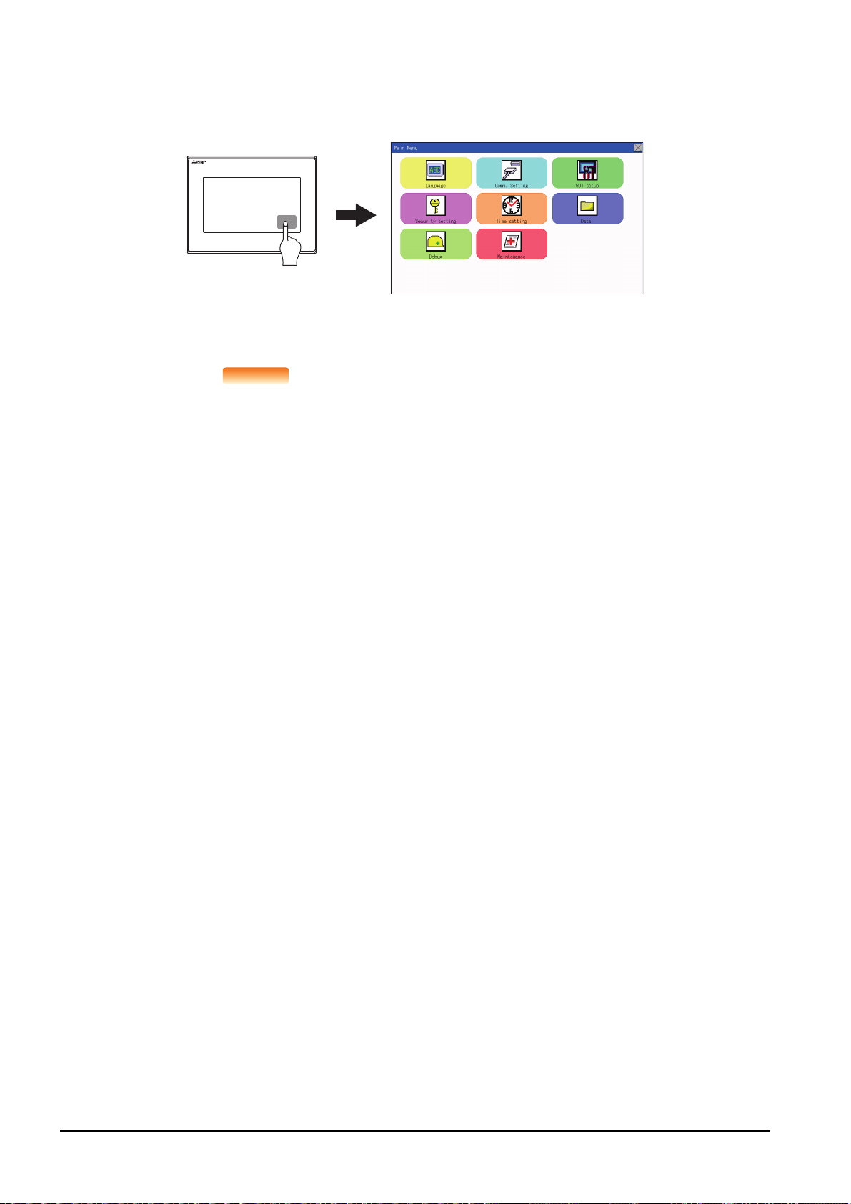
(3) When touching special function switch (utility)
POINTPOINTPOINT
If you touch the special function switch (utility) while user-created screen is displayed, the main menu is displayed.
The special function switch (utility) can be set as a touch switch that is displayed on a user-created screen by GT
Designer3.
Special function switch
(Utility)
For the details of the special function switch, refer to the following.
➠ GT Designer3 (GOT2000) Help
When limiting the display and operation of the utility
When limiting the display and operating users, set a password to the GOT using GT Designer3.
If a user tries to display the main menu of the utility, the password is displayed.
Refer to the following for the details related to the password setting.
➠ GT Designer3 (GOT2000) Help
9 - 6
9.3 Utility Display
Page 65

9.3.2 Utility basic configuration
Title display
Title display
The basic configuration of utility is as follows.
Title display Close/Return button
(1) Title display
The screen title name is displayed in title display part.
Display
(2) Close/Return button
When a middle screen of the layers is displayed, if the [ ] (Close/return) button in the right corner of screen is
touched, returns to the previous screen.
If this button is touched when directly displayed from monitor screen, the screen is closed and returns to monitor
screen.
(3) Scroll button
For screens in which the content does not fit on one screen page, there is a right or down scroll button on the screen.
Scroll one line/column.
Scroll window.
UTILITY FUNCTION
9
9.3 Utility Display
9 - 7
Page 66
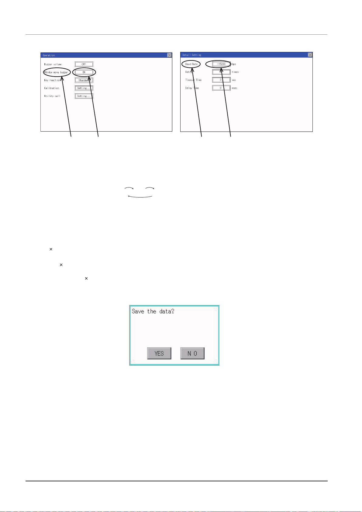
9.3.3 Basic operation of settings change
Description Selection button Description Selection button
■1. Change of setting value
(1) Setting item, select button
Touch the select button to change the settings.
The setting methods differ depending on the setting items.
The following types of setting method are available.
(a) Switching the setting value
The button repeats every time it is pressed.
(b) Enter the setting value with a keyboard.
Use these keys to enter numerical values. Touch the button to display a keyboard on the GOT screen.
For the keyboard operations, refer to the next page.
(c) Move to another setting screen.
Touch the button to move to each setting screen.
For the setting method of each setting item, refer to the setting operation of each setting screen.
(2) [ ] (Close/Return) button
Reflect or cancel the changed settings.
(a) [ ] (Close/Return) button
Touching this button closes the screen. Depending on the setting item, the GOT restarts.
Touch the [ ] button, and then the dialog box shown below is displayed.
(If no setting is changed, the dialog is not displayed.)
Operate following the message of the dialog box.
SHORT LONG OFF
9 - 8
9.3 Utility Display
Page 67

■2. Keyboard operations
Step 1. Touch the numerical value to be changed.
Step 2. The keyboard for entering numerical values and a cursor are displayed.
The display position of the keyboard differs depending on the position of the touched numerical value.
(The keyboard is displayed at a position that does not disturb users to input numerical values.)
Cursor
keyboard
Step 3. Input numerical value by the keyboard.
• [0] to [9] Key: Enter numerical values.
• [Enter] Key: Completes the numerical value input and closes the keyboard.
• [Cancel] Key: Cancels the numerical value input and closes the keyboard.
• [Del] Key: Deletes one character.
• [AC] Key: Deletes all characters.
• [*] key and the keys which are not mentioned do not function.
Step 4. Touching the [Enter] key completes the numerical value input and closes the keyboard.
UTILITY FUNCTION
9
9.3 Utility Display
9 - 9
Page 68

9 - 10
9.3 Utility Display
Page 69
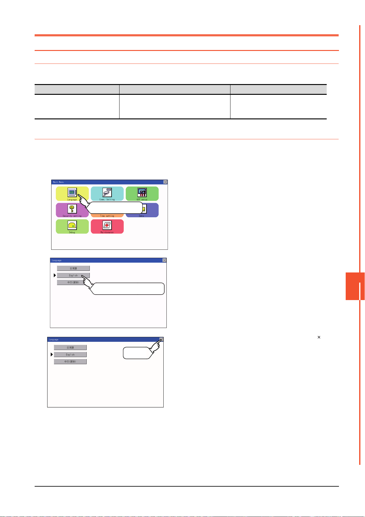
10. LANGUAGE SETTING (LANGUAGE)
Main Menu
Touch [Language]
10.1 Display language setting
10.1.1 Display language setting function
This function allows display language selection.
The items which can be set are shown below.
Item Description Setting range
Display language in which the utility functions
Language
and dialog windows are displayed can be
selected or confirmed in this menu
10.1.2 Language setting operation
■1. Language
Japanese/English/Chinese
<At factory shipment: Chinese>
Step 1. Touch [Language] to bring up the set up
screen.
Touch a language to be displayed.
Touch
Step 2. Select a display language by touching
the corresponding button.
Step 3. After changing the setting, touch the [ ]
button.
The setting is saved and the setting
screen is closed.
LANGUAGE SETTING (LANGUAGE)
10
10.1 Display language setting
10 - 1
Page 70

POINTPOINTPOINT
Switching the display language of the utility by devices
Any device can be used for switching the display language of the utility. For details, refer to the
following.
➠ GT Designer3 (GOT2000) Help
When using devices to switch the display language of the utility, it does not change even if the
display language is switched from the GOT utility screen.
10 - 2
10.1 Display language setting
Page 71

11. COMMUNICATION INTERFACE SETTING (COMMUNICATION SETTING)
Main Menu Comm. Setting
Touch
[Comm. Setting].
Touch
[Standard I/F].
Standard I/F
The following communication interfaces can be set.
Item Functions overview Reference
Standard I/F
Assigning channel number and communication driver to
communication interface
➠ 11 .1
GOT IP Address Configuring GOT Ethernet setting
Ethernet communication Displaying the contents of Ethernet setting, changing the host
Comm. Monitor Checking the serial communication port communication
Comm. Setting
Ethernet check Checking the Ethernet communication port communication
Transparent mode
Keyword
Setting the channel No. to be used for the communication for the FA
transparent function
Setting or deleting sequence program protection key words and
canceling sequence program protection status for the FXCPU
connection
11.1 Standard I/F Setting
11.1.1 Standard I/F functions
Function Description
Channel no. display Displays the channel number (CH No) that has been assigned by drawing
Communication driver display Displays the communication driver that has been assigned by drawing software
Communication parameters display
Displays the communication parameters of the controllers that has been assigned by
drawing software
➠ 11 .2
➠ 11 .3
➠ 11 .4
➠ 11 .5
➠ 11 .6
➠ 11 .7
11.1.2 Standard I/F display operation
COMMUNICATION INTERFACE SETTING (COMMUNICATION SETTING)
11
11.1 Standard I/F Setting
11 - 1
Page 72

11.1.3 Display contents of standard I/F
Standard interface display BOX
Channel No.
specification
menu BOX
Driver display BOX
Drv
button
Standard I/F-3(USB)
Standard I/F-1(RS-422)
Standard I/F-4(Ethernet)
Standard I/F-2(RS-232)
Described below are the display items on the standard I/F setting menu and their functions.
■1. Display item
(1) Standard interface display BOX
The standard interface includes the following four types.
Standard I/F-1(RS422): For communication with PLC, microcomputer and other equipment
Standard I/F-2(RS232): For communication with PLC, PC (drawing software), modem, other equipment,
bar code reader and transparent
Standard I/F-3(USB): For communication with PC (drawing software) and transparent
Standard I/F-4(Ethermet): For communication with PC (drawing software) and other equipment
11 - 2
(2) Channel No. specification menu BOX
Set a channel number to be used by the standard interface.
➠ 11.1.5 Channel setting operation
For the detail of the drivers which can be assigned to each channel, refer to this section (3).
0: Set when the communication interface is not used.
1, 2: Set when connecting to a controller.
8: Set when connecting to a bar code reader or RFID.
9:
*:
• "9" is automatically set to the standard I/F-3(USB).
*1
11.1 Standard I/F Setting
Set when connecting to a PC (drawing software).
Set this channel when the gateway function (except when the connection with controllers is the
Ethernet connection) or the Ethernet download function is used.
Page 73

(3) Driver display BOX
POINT
Drv
Drv
(a) The driver display box displays the names of communication drivers assigned to channels or the
communication drivers set in the communication settings of drawing software.
For details of the communication drivers to be displayed, refer to the following.
➠ GT Designer3 (GOT2000) Help
(b) "Disuse" is displayed in the driver display box in the following cases:
• The communication driver is not installed.
➠ 15.2 OS information
• "0" is set in the channel number specification menu box.
(c) The channel number of the standard I/F-3(USB) is fixed to "9".
(4) button
Displays the driver setting screen.
Select the driver to use on the driver setting screen.
➠ 11.1.6 Driver setting operation
The button is displayed in the following case.
• When a channel number other than channel 0 or 9 is set to the standard I/F-1, standard I/F-2, and standard I/F-4
POINT
POINT
Precautions for communication between GOT and connected devices
(1) Installing [Communication driver] and downloading [Communication Settings]
To perform communication with the connected device, the following actions are necessary.
1) Installing communication drivers (Up to 2 drivers)
2) Assigning channel numbers and communication drivers to communication interfaces
3) Downloading contents (project data) assigned in step 2)
Perform 1), 2) and 3) with drawing software.
For details, refer to the following.
➠ GT Designer3 (GOT2000) Help
(2) When the communication settings have not been downloaded
If the communication settings have not been downloaded with drawing software, set the
communication settings on the drawing software or in the GOT utility screen.
COMMUNICATION INTERFACE SETTING (COMMUNICATION SETTING)
11
11.1 Standard I/F Setting
11 - 3
Page 74

11.1.4 Detail information setting operation
Touch [Driver display BOX].
Ex. 4800bps 9600bps 19200bps
■1. For Standard I/F-1(RS422) and Standard I/F-2(RS232)
Step 1. Touch each driver display box of the standard
Step 2. The screen jumps to the detailed information
I/F-1 and standard I/F-2.
screen and the communication parameter will
appear.
Step 3. Touch the numerical values of baud rate to
switch them repeatedly.
The numerical values are set using the tenkey depending on the setting.
"0" to "9":
Use these keys to enter numerical values.
Enter "0" to disable the screen saver function.
"ESC":
Closes the ten-key window without saving any
value entered
"AC":
Deletes the entire string of numerical
characters that are being entered
"DEL":
Deletes a digit from a string of numerical
characters that are being entered
"ENT":
Enters the value for the clock that has been
entered and closes the ten-key pad window
"+/-":
Switches between positive and negative
values (Only positive values are valid for the
clock setting.)
".":
Invalid key (not used)
11 - 4
11.1 Standard I/F Setting
Page 75

POINT
Step 4. Touch the [ ] button to display the window
confirming whether to save the settings.
Step 5. Touch the [YES] button to save the settings
and restart. Touch the [NO] button to discard
the changes.
POINT
POINT
Communication parameters
The types of items that are in the communication parameter setting menu depend on the type of
communication driver that is installed on the GOT in use.
Refer to the section below for the setting contents of various drivers.
➠ GT Designer3 (GOT2000) Help
COMMUNICATION INTERFACE SETTING (COMMUNICATION SETTING)
11
11.1 Standard I/F Setting
11 - 5
Page 76

■2. For Standard I/F-4(Ethernet)
POINTPOINTPOINT
Step 1. Touch the driver display box of a
communication parameter to be set.
Step 2. The screen is switched to the
communication detail setting. Set the
communication parameter on this
screen.
GOT IP address setting
➠ 11.2 GOT IP Address Setting
Step 3. When the [ ] button is touched, it
returns to the previous screen.
Step 4. Touch the [ ] button to display the
window confirming whether to save the
settings.
Step 5. Touch the [YES] button to save the
settings and restart. Touch the [NO]
button to discard the changes.
Communication parameter setting by drawing software
Set the communication parameter for each communication driver by selecting [Common]
[Controller Setting].
➠ GT Designer3 (GOT2000) Help
11 - 6
11.1 Standard I/F Setting
Page 77

11.1.5 Channel setting operation
Touch
Touch
■1. Channel number setting operation
Step 1. Touch the channel No. specification
menu box to be set.
Step 2. When the channel setting window
appears, select the channel number.
Step 3. When the channel number is selected,
the settings are fixed and the window
returns to the previous one. Therefore,
touch the [ ] button.
Step 4. Touch the [ ] button to display the
window confirming whether to save the
settings.
Step 5. Touch the [YES] button to save the
settings and restart. Touch the [NO]
button to discard the changes.
COMMUNICATION INTERFACE SETTING (COMMUNICATION SETTING)
11
11.1 Standard I/F Setting
11 - 7
Page 78

11.1.6 Driver setting operation
Touch [Drv]
Touch
■1. Driver setting operation
Step 1. Touch [Drv] button to bring up the driver
setting window.
Step 2. The available driver names are
displayed on the driver setting screen.
Select the driver to use.
Step 3. When the channel number is selected,
the settings are fixed and the window
returns to the previous one. Therefore,
touch the [ ] button.
Step 4. Touch the [ ] button to display the
window confirming whether to save the
settings.
Step 5. Touch the [YES] button to save the
settings and restart. Touch the [NO]
button to discard the changes.
11 - 8
11.1 Standard I/F Setting
Page 79

11.2 GOT IP Address Setting
This section describes the GOT Ethernet setting.
The GOT Ethernet setting can also be set with drawing software. For details, refer to the following.
➠ GT Designer3 (GOT2000) Help
11.2.1 Standard
The table below shows the communication setting items and setting range.
Communication setting items Setting range Remark
IP Address 0.0.0.1 to 223.255.255.254
Subnet Mask
Default gateway
Per. S/W port No.
Transparent port No.
*1
*1
192.0.0.0 to 255.255.255.252
0.0.0.1 to 223.255.255.254
1024 to 5010, 5014 to 49152,
49171 to 65534
1024 to 5010, 5014 to 49152,
49171 to 65534
*1 Set the value "0.0.0.0" when not using the subnet mask and default gateway.
If a value outside the setting range is entered, the error
message "SET NUMBER IS INCORRECT." appears.
Set the port number for the GOT download.
Set the port number for the transparent of the GOT.
11.2.2 Display operation of GOT IP address
Main Menu Comm. Setting
Touch
[Comm. Setting].
Touch
[GOT IP Address].
COMMUNICATION INTERFACE SETTING (COMMUNICATION SETTING)
11
GOT IP Address
11.2 GOT IP Address Setting
11 - 9
Page 80

11.2.3 Setting operation
Touch the numerical part
of the octet to be changed.
Touch
Step 1. Touch the numerical part of the octet to
be changed among the 1st to 4th octets.
Step 2. When the ten-key pad appears, enter a
numerical value in up to 3 digits, and
touch the key.
If a numerical value outside the setting
range is entered, the following error
message appears. Enter a numerical
value again.
Touch[×]
For the details of the setting range, refer
to the following.
➠ 16.3.1 Specifications
Step 3. If necessary, change the setting of [Per.
S/W port No.] and [Transparent port
No.].
Step 4. After the setting change, touch the [×]
key.
11 - 10
11.2 GOT IP Address Setting
Step 5. When the screen shown on the left
appears, touch the [YES] key.
Touch [YES]
Page 81
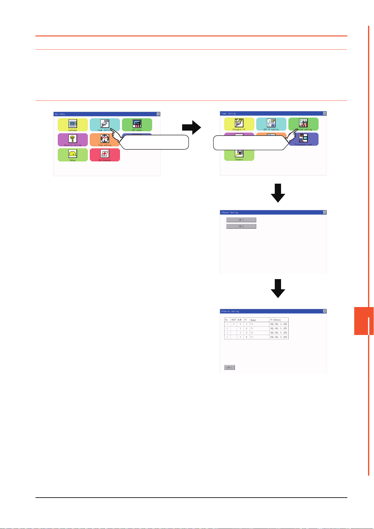
11.3 Ethernet Communication
Channel Setting
Ethernet setting
Comm. SettingMain menu
Touch [Comm. Setting].
Touch [Ethernet setting].
11.3.1 Setting function for Ethernet communication
The contents of the Ethernet set in GT Designer3 can be checked.
The setting of the host station can be changed.
For the Ethernet setting, refer to the following.
➠ GOT2000 Series Connection Manual for the controller used
11.3.2 Display operation of Ethernet communication
COMMUNICATION INTERFACE SETTING (COMMUNICATION SETTING)
11
11.3 Ethernet Communication
11 - 11
Page 82

11.3.3 Display contents of Ethernet setting
POINTPOINTPOINT
The following describes the setting items and the display contents of the Ethernet setting.
(2)
(1)
(1) Channel select tab
Channels can be switched.
Switching to the channel which does not have the Ethernet setting is not available.
(2) Ethernet setting items
The contents of the Ethernet setting configured in GT Designer3 are displayed.
Changing [Host], [Net No.], [Station No.] and [IP Address] are available.
➠ Change of host
➠ Change of Net No.
➠ Change of station No.
➠ Change of IP address
(1) How to cancel the change of the setting in the [Ethernet setting] screen.
Cancel the settings changed in the [Ethernet setting] screen with the [Restore default
settings] button.
The changed settings remain until they are canceled with the [Restore default settings]
button.
The changed settings are not canceled even if writing the project data or system application
to the GOT.
When the project data is written to the GOT without canceling the changed settings, those
changed settings are reflected to the Ethernet setting of the written project data.
(If the written project data does not have a channel with same Ethernet settings as that of the
channel changed in [Ethernet setting] screen, the changed settings are not reflected.)
11 - 12
11.3 Ethernet Communication
Page 83

■ Change of host
Step 1. Touch the device to be set as the host.
Step 2. After the setting change, touch the [×]
key. When the screen shown on the left
appears, touch the [YES] key.
Touch YES.
■ Change of Net No.
Step 1. Touch the Net No. to be changed, and
input the network No. to be changed by
the numeric keypad displayed.
COMMUNICATION INTERFACE SETTING (COMMUNICATION SETTING)
11
Step 2. After the setting change, touch the [×]
key. When the screen shown on the left
appears, touch the [YES] key.
Touch YES.
11.3 Ethernet Communication
11 - 13
Page 84

■ Change of station No.
Touch YES.
Touch YES.
Step 1. Touch the station No. to be changed,
and input the station No. of the
destination Ethernet module to be
changed by the numeric keypad
displayed.
Step 2. After the setting change, touch the [×]
key. When the screen shown on the left
appears, touch the [YES] key.
■ Change of IP address
Step 1. Touch the IP address to be changed,
input the destination IP address to be
changed by the numeric keypad
displayed.
Step 2. After the setting change, touch the [×]
key. When the screen shown on the left
appears, touch the [YES] key.
11 - 14
11.3 Ethernet Communication
Page 85

11.4 Communication Monitor
Comm. SettingMain Menu
Comm. Monitor
Touch
[Comm. Setting].
Touch
[Comm. Monitor].
11.4.1 Communication monitor functions
Function Description
Communication port-selection status display Indicates the connection status of Standard I/F-1 and I/F-2.
Communication status display Displays the communication status (SD: send, RD: receive)
Communication error status display Displays an error message when a communication error occurs
11.4.2 Communication monitor display operation
COMMUNICATION INTERFACE SETTING (COMMUNICATION SETTING)
11
11.4 Communication Monitor
11 - 15
Page 86
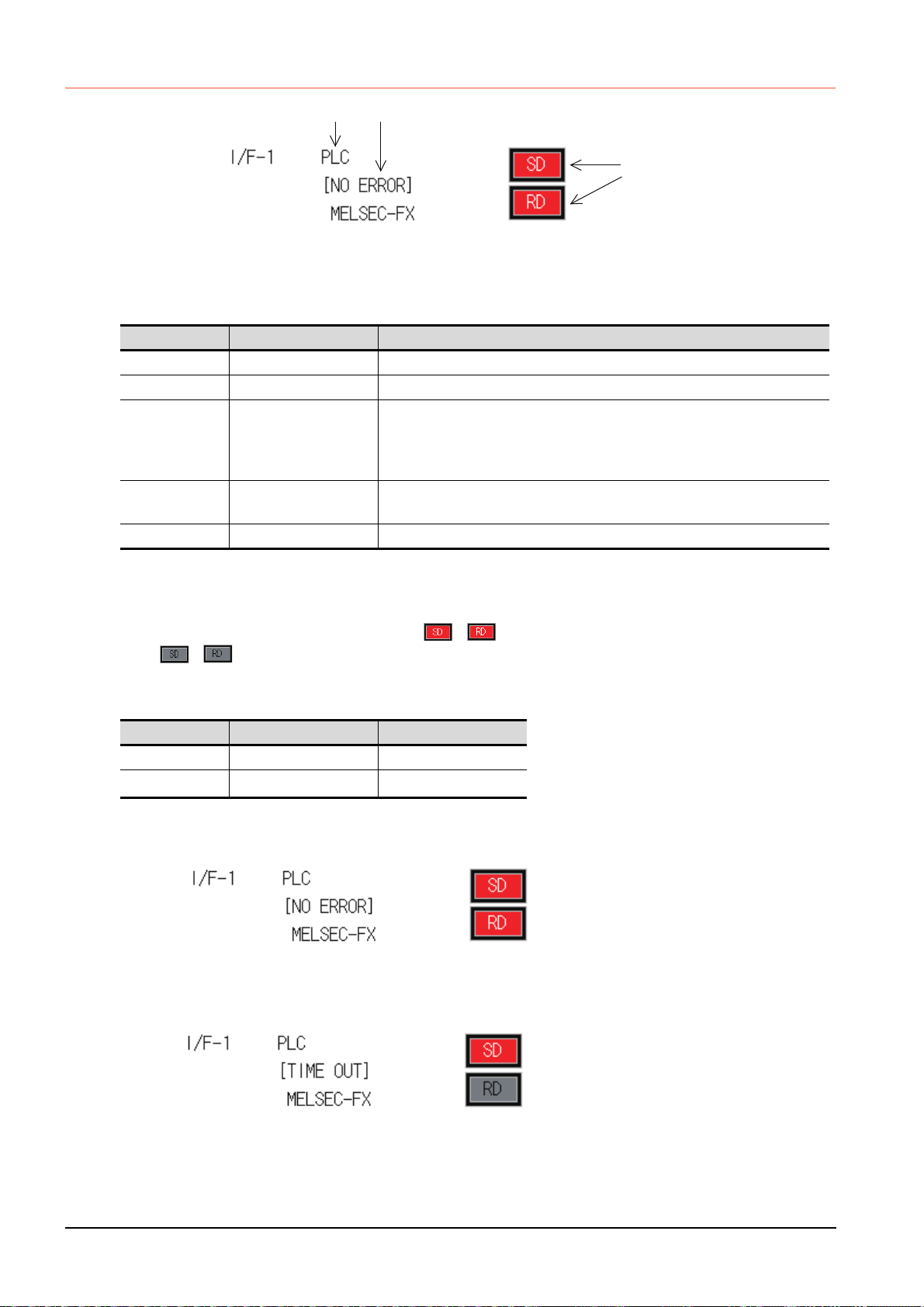
11.4.3 Screen display content
(1) (3)
(2)
The SD and RD symbols for I/F-1
(1) Connection status of the communication ports
Indicates the connection status of Standard I/F-1 and I/F-2.
Listed in the table below are display items and the connection status (channel number).
Display item Channel number Remark
PLC Ch1 "PLC" appears when connected to a controller (PLC or microcomputer)
Barcode Ch8 "BCR" appears when connected to a bar code reader
"TRANS." appears when the controller that is allocated to one of the
TRANS. Ch9
Host(PC) Ch9
Printer ChA Appears when connected to a printer.
communication ports supports the transparent mode
"TRANS." automatically changes to "PC" when communicating with drawing
software
"PC" appears when the controller that is allocated to one of the communication
ports does not support the transparent mode
(2) Communication status
Displays the communication status of each communication port.
The SD and RD symbols appear in white on red ( , ) while data are being sent or received, and in black on
gray ( , ) at other times. They may appear lit depending on the communication status.
The SD and RD symbols on the screen indicate normal communication or cable disconnection.
Setting example
Port Channel number Controller type
I/F-1 Ch1 MELSEC-FX
I/F-2
Ch8
, Ch9
-
(a) [During normal communication (with connection to a device that supports the transparent mode)]
(b) [When the connecting cable with the controller is disconnected]
Only the SD symbol next to I/F-1 blinks.
11 - 16
11.4 Communication Monitor
Page 87

(3) Communication error status
Communication error status of each port is displayed on this screen.
The following table describes the communication status that each display item shows
Display item Status Action
NO ERROR No error Communication is executed normally.
The receive data is sent continuously with a short interval.
ERR Ovr. Overrun error
ERR Frm. Framing error
ERR Prt. Parity error
ERR Text Text error
TIME OUT Communication timeout
ERR Line Control line error
ERR Cmd. Command error
Let the baud rate (communication speed) be equivalent between the GOT and
counterpart equipment.
The communication frames of GOT and PLC are inconsistent.
Confirm the communication settings of GOT and PLC, such as data length, stop
bit and baud rate.
The parity check conditions of GOT and PLC are inconsistent.
Let the parity check condition (odd or even) of GOT and PLC be consistent.
The sum data is inconsistent. Or the contents of the receive data are not
consistent with the send command from the GOT.
Let the communication settings and contents of data be consistent between the
GOT and counterpart equipment. (If NAK is received while the GOT is
connected to the microcomputer board, a text error occurs.)
Though receiving is started, receive data is not sent.
Check the wiring between the GOT and its communication target.
(When the GOT is connected to the microcomputer board, confirm the
terminator, CR, wiring, etc.)
The control line is not operating correctly.
Confirm the wiring of the control line.
A command contained in the receive data is not consistent with the send
command from the GOT.
.
COMMUNICATION INTERFACE SETTING (COMMUNICATION SETTING)
11
11.4 Communication Monitor
11 - 17
Page 88

11.5 Ethernet Check
Ethernet check
Main Menu
Debug
Touch
[Debug].
Touch
[Ethernet check].
( 9.2 Utility Function List)
■1. Ethernet check function
The Ethernet status check function sends a ping to check the connection status of Ethernet.
■2. Display operation of Ethernet check
11 - 18
11.5 Ethernet Check
Page 89

■3. Operation of Ethernet status check
Touch
Step 1. If the select button of [Destination IP] is
touched, a keyboard is displayed.
Enter the IP address of the other terminal
with the keyboard.
<Default: 192.168.3.39>
Step 2. If the [Send ping] button is touched, a
ping is sent to the IP address entered in
[Destination IP]. The timeout time is 5sec.
• When the communication is completed
The [Response received.] dialog box is
displayed.
• When a communication error occurs
The [Timeout occurred.] dialog box is
displayed.
COMMUNICATION INTERFACE SETTING (COMMUNICATION SETTING)
11
11.5 Ethernet Check
11 - 19
Page 90

11.6 Setting the Transparent Mode
Transparent mode
Main Menu
Comm. Setting
To uc h
[Comm Setting]
Touch [Transparent mode]
( 9.2 Utility Function List)
■1. Function of the transparent mode
When using the multi-channel function, the channel No. of a controller to which the FA transparent function is executed
can be set. For the multi-channel function and the FA transparent function, refer to the following.
➠ GOT2000 Series Connection Manual (Mitsubishi Product) For GT Works3 Version1
Function Description Setting range
ChNo. The channel No. of a controller to which the FA transparent function is executed can be set.
■2. Display operation the transparent mode setting
1/2
(Default: 1)
■3. Operation the transparent mode
11 - 20
11.6 Setting the Transparent Mode
Step 1. When the transparent ChNo.
(numerical part) on the left is touched,
the screen for selecting a
communication driver is displayed.
Select the channel to execute the FA
transparent function.
Step 2. If the [ ] button is touched, it returns to
the GOT setup screen.
Page 91
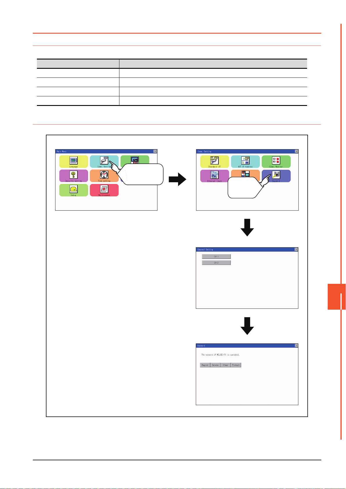
11.7 Keyword
Main Menu Comm. Setting
Channel Setting
Keyword
Touch
[Comm. Setting]
Touch
[Keyword]
11.7.1 Keyword functions
The operation related to a keyword of the FX series PLC can be performed.
Function Description
Regist Keyword is registered.
Delete Registered keyword is deleted.
Clear Keyword protection is cleared.
Protect A keyword with cleared protection is reactivated for protection.
11.7.2 Keyword display operation
COMMUNICATION INTERFACE SETTING (COMMUNICATION SETTING)
11
11.7 Keyword
11 - 21
Page 92

11.7.3 Regist
Touch
Keyword is registered.
Step 1. Touch "Regist" to display the selection
screen for the registration.
For the FX series PLC, which is not
compatible with Customer Keyword, the
keyword entry screen of [Step3] is
displayed. Start the operation from
[Step3].
For the Customer Keyword compatible
models, refer to the manual of the PLC
to be used.
Step 2. Select [Keyword] or [Keyword+Custom].
To register only Keyword and 2nd
keyword, touch [Keyword].
To register Customer Keyword, touch
[Keyword+Custom].
Touch
Step 3. Input a keyword.
Touch the display part of the keyword to
be registered.
Step 4. The keyboard for entering a keyword is
displayed. Character types to be input
can be changed by touching the [KEY]
button. Enter a keyword and touch the
[ENT] key.
For the keyword, 8 digits from 0 to 9 or
A to F must be set.
Touch
11 - 22
11.7 Keyword
Page 93

Step 5. After completing the keyword entry,
Touch
Touch
All Protect Write Protect R/W Protect
Touch
Touch
touch [Next].
When [Keyword+Custom] is selected on
the selection screen for the registration,
the Customer Keyword entry screen is
displayed. Enter it in the same way as
for Keyword and 2nd keyword.
Step 6. Set Registration conciliation.
Touch Registration conciliation to
change the setting contents.
Step 7. After setting Registration conciliation,
touch the [Execute] key.
The registration of the keyword is
completed.
Step 8. The registration of the keyword is
completed.
Touch [OK].
COMMUNICATION INTERFACE SETTING (COMMUNICATION SETTING)
11
11.7 Keyword
11 - 23
Page 94
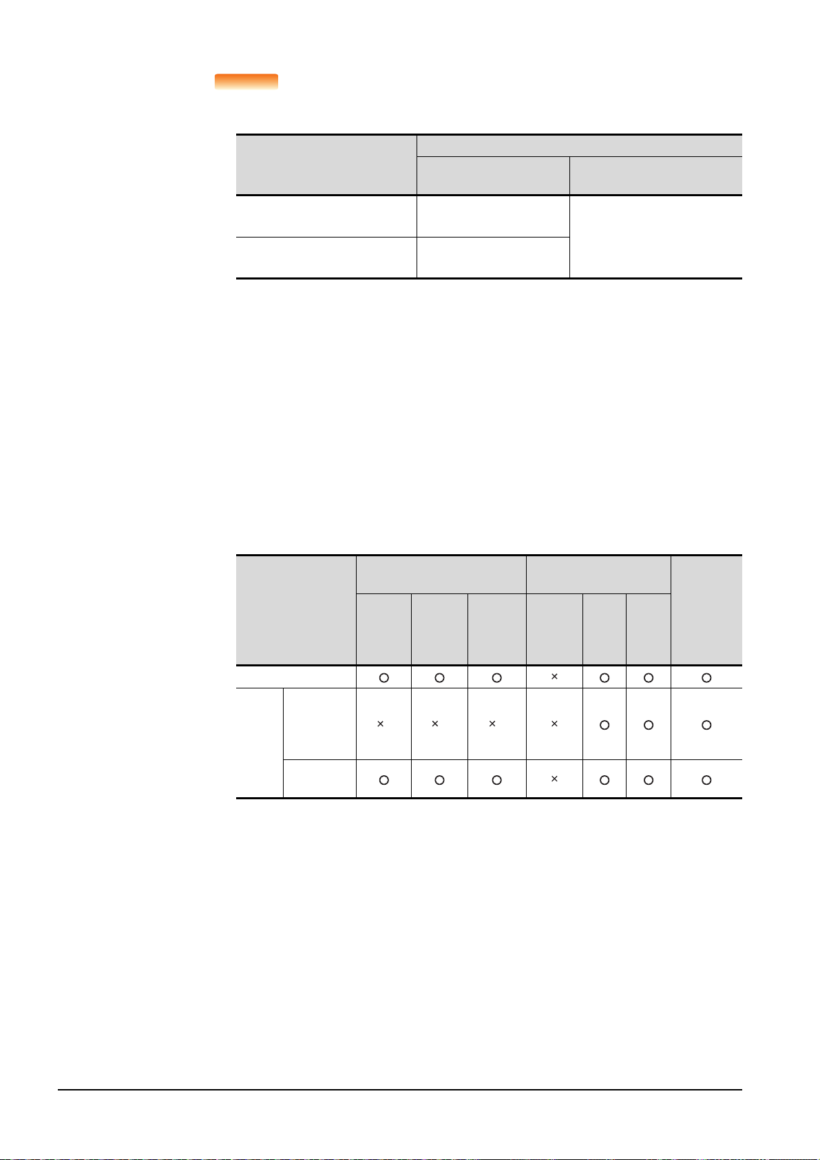
POINTPOINTPOINT
(1) Selection availability of Registration conciliation
The following table lists the PLCs that can select Registration conciliation.
Setting
Target PLC
FX PLC
compatible with 2nd keyword
FX PLC
not compatible with 2nd keyword
*1 Refer to the manual for the PLC in use for the models that are compatible with the 2nd keyword.
*2 Registration options can be selected among "R/W Protect", "Write Protect", or "All online operation
protection". For access restrictions of each setting, refer to the manual of the PLC to be used.
*1
*1
When keyword and
2nd keyword are registered
Registration options*2
can be selected.
-
When only keyword is registered
selected.
*2
cannot be
Registration options
(2) Selection of keyword protection level
For the devices which can perform the online operation of FX PLC, 3 levels of protection can
be set.
When the monitoring or setting change by online devices is needed, set the keyword taking
the following into consideration.
(a) When only keyword is registered
Protection level is selected by the head character of keyword.
All Protect: Set the keyword starting with one of A, D to F, or 0 to 9.
Read/incorrect write protection: Set the keyword starting with B.
Erroneous write prohibition: Set the keyword starting with C.
(b) When keyword and 2nd keyword are registered
(3) Applicability of monitoring for each keyword protection level
The applicability of monitoring for each protection level is as follows.
When only keyword is registered
Item
Device monitoring
T, C setting
values and
Device
change
file register
(from D1000)
Other than
the above
*1 When the T, C set values are specified indirectly, changing devices is available.
All
operation
protect
*1
Read/
Incorrect
write
protection
*1 *1
Erroneous
write
prohibition
When keyword and 2nd
keyword are registered
All online
operation
protection
R/W
Protect
Write
Protect
Keyword
unregistered/
protection
canceled
(4) Difference between "All online operation protection" and "All Protect"
When "All online operation protection" is selected, both device display and input by the
programming tool or GOT are prohibited.
When "All Protect" is selected, device display and input are possible although operations by
the programming tool are all prohibited.
11 - 24
11.7 Keyword
Page 95

11.7.4 Delete
Touch
Touch
Target PLC Setting
FX PLC
compatible with
2nd keyword
Input a keyword to be deleted.
FX PLC
not compatible with
2nd keyword
Input a keyword to be deleted only into
"keyword".
"2nd keyword" is ignored.
Touch
Touch
Registered keyword is deleted.
Step 1. Touch [Delete] to display the keyword
entry screen.
Step 2. Input a keyword.
Touch the display part of the registered
keyword.
Step 3. The keyboard for entering a keyword is
displayed. Enter a keyword and touch
the [ENT] key. Character types to be
input can be changed by touching the
[KEY] button.
Step 4. After completing the keyword entry,
touch [Next].
COMMUNICATION INTERFACE SETTING (COMMUNICATION SETTING)
11
11.7 Keyword
11 - 25
Page 96

Step 5. Touch the [Execute] key.
Touch
Touch
Step 6. The keyword is deleted.
Touch [OK].
11 - 26
11.7 Keyword
Page 97

11.7.5 Clear
Touch
Touch
Target PLC Setting
FX PLC compatible
with customer keyword
Input a keyword or customer keyword
to clear the protection.
FX PLC compatible
with 2nd keyword
Input a keyword to clear the protection.
FX PLC not
compatible with 2nd
keyword
Input a keyword into "keyword" to clear
the protection.
"2nd keyword" is ignored.
Touch
Touch
To access an FX PLC where a keyword has been registered, keyword protection is cleared.
Step 1. Touch [Clear] to display the keyword
entry screen.
Step 2. Input a keyword.
Touch the display part of the registered
keyword.
Step 3. The keyboard for entering a keyword is
displayed. Enter a keyword and touch
the [ENT] key. Character types to be
input can be changed by touching the
[KEY] button.
Step 4. After completing the keyword entry,
touch [Next].
COMMUNICATION INTERFACE SETTING (COMMUNICATION SETTING)
11
11.7 Keyword
11 - 27
Page 98

Touch
Touch
Step 5. Touch the [Execute] key.
Step 6. The protection is cleared.
Touch [OK].
11 - 28
11.7 Keyword
Page 99
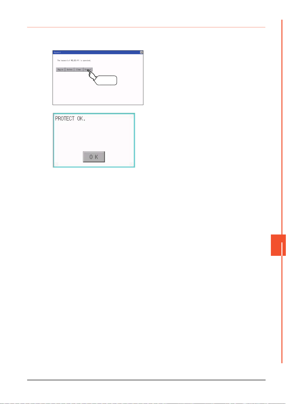
11.7.6 Protect
Touch
A keyword with cleared protection is reactivated for protection. Keyword protection function is valid when the 2nd keyword is
registered.
Step 1. Touch [Protect] to switch to the keyword
protection status.
Step 2. The keyword is protected.
Touch [OK].
COMMUNICATION INTERFACE SETTING (COMMUNICATION SETTING)
11
11.7 Keyword
11 - 29
Page 100

11 - 30
11.7 Keyword
 Loading...