


C
MIT
SUBIS
C
HI ELECTRI
GOT Series
Human Machine Interface
Operating Manual (Introductory)
Art.-Nr.: 136208
01 08 2000
SH-080116-A
GOT900
MITSUBISHI ELECTRI
INDUSTRIAL AUTOMATION
SAFETY PRECAUTIONS
•
(Always read these instructions before using this equipment.)
Before using this product, please read this manual and the relevant manuals introduced in this manual
carefully and pay full attention to safety to handle the product correctly.
The instructions given in this manual are concerned with this product. For the safety instructions of the
programmable controller system, please read the CPU module user's manual.
In this manual, the safety instructions are ranked as "WARNING" and "CAUTION".
•
WARNING
CAUTION
Note that the !CAUTION level may lead to a serious consequence according to t he circumstances.
Always follow the instructions of both levels because they are important to personal safety.
Please save this manual to make it accessible when required and always forw ard it to the end user.
Indicates that incorrect handling may cause hazardous conditions,
resulting in death or severe injury.
Indicates that incorrect handling may cause hazardous conditions,
resulting in medium or slight personal injury or physical damage.
[Design Precautions]
!
WARNING
Some failures of the GOT main unit, communication board or cable may keep the outputs on or
•
off.
An external monitoring circuit should be provided to check for output signals which may lead t o a
serious accident.
Not doing so can cause an accident due to false output or malfunction.
If a communication fault (including cable disconnection) occurs during monitoring on t he GOT,
•
communication between the GOT and PLC CPU is suspende d and the GO T becomes
inoperative.
For bus connection : The CPU becomes faulty and the GOT inoperative.
A system where the GOT is used should be configured to perform any significant operation to
the system by using the switches of a device other than the GOT on the assumption that a GOT
communication fault will occur .
Not doing so can cause an accident due to false output or malfunction.
!
CAUTION
Do not bundle the control and communication cables with main-circuit, power or other wiring.
•
Run the above cables separately from such wiring and keep them a minimum of 100mm apart.
Not doing so noise can cause a malfunction.
A - 1 A - 1
[Mounting Precautions]
!
WARNING
Before installing or removing t he GO T main unit t o or from an enclos ure, alway s s wit ch off th e
•
GOT power externally in all phases.
Not doing so can cause a module failure or malfunction.
Before loading or unloading the communication board to or from the GOT, alway s switch off the
•
GOT power externally in all phases.
Not doing so can cause a module failure or malfunction.
!
CAUTION
The GOT should be used in the environment given in the general specifications of the GO T
•
user's manual.
Not doing so can cause an electric shock, fire, malfunction or product damage or deterioration.
When mounting the GOT main unit to an enclosure, tighten the mounting screws in the specifie d
•
torque range.
Undertightening can cause a drop, short circuit or malfunction.
Overtightening can cause a drop, short circuit or malfunction due to the damage of the screws or
module.
When loading the communication board to the GOT main unit, fit it to the connection interface of
•
the GOT and tighten the mounting screws in the specified torque range.
Undertightening can cause a drop, failure or malfunction.
Overtightening can cause a drop, failure or malfunction due to the damage of the screws or
module.
A - 2 A - 2
[Wiring Precautions]
!
WARNING
Before starting wiring, always switch off the GOT power externally in all phases.
•
Not doing so may cause an electric shock, product damage or malfunction.
!
CAUTION
Please make sure to ground FG terminal, LG terminal, and protective ground terminal of the
•
GOT power supply unit by applying Class D Grounding (Class 3 Gr ounding Method) or higher
which is used exclusively for the GOT.
Not doing so may cause an electric shock or malfunction.
Correctly wire the power supply module on the GOT after confirming the rated voltage and
•
terminal arrangement of the product.
Not doing so can cause a fire or failure.
Tighten the terminal screws of the GOT power supply section in the specified torque range.
•
Undertightening can cause a short circuit or malfunction.
Overtightening can cause a short circuit or malfunction due to the damage of the screws or
module.
Exercise care to avoid foreign matter such as chips and wire offcuts entering the module.
•
Not doing so can cause a fire, failure or malfunction.
Plug the bus connection cable by inserting it into the connector of the connected module until it
•
"clicks".
After plugging, check that it has been inserted snugly.
Not doing so can cause a malfunction due to a contact fault.
Plug the communication cable into the connector of the connected module and tighten the
•
mounting and terminal screws in the specified torque range.
Undertightening can cause a short circuit or malfunction.
Overtightening can cause a short circuit or malfunction due to the damage of the screws or
module.
[Test Operation Precautions]
!
WARNING
Before performing test operation (bit device on/off, word device's present value changing,
•
timer/counter's set value and present value changing, buffer memory's present value changing)
for a user-created monitor screen, read the manual carefully to fully understand how to operate
the equipment.
During test operation, never change the data of the devices which are used to perform
significant operation for the system.
False output or malfunction can cause an accident.
A - 3 A - 3

[Startup/Maintenance Precautions]
!
WARNING
When power is on, do not touch the terminals.
•
Doing so can cause an electric shock or malfunction.
Before starting cleaning or terminal screw retightening, always switch off the power externally in
•
all phases.
Not switching the power off in all phases can cause a module failure or malfunction.
Undertightening can cause a short circuit or malfunction.
Overtightening can cause a short circuit or malfunction due to the damage of the screws or
module.
!
CAUTION
Do not disassemble or modify the module.
•
Doing so can cause a failure, malfunction, injury or fire.
Do not touch the conductive and electronic parts of the module directly.
•
Doing so can cause a module malfunction or failure.
The cables connected to the module must be run in ducts or clamped.
•
Not doing so can cause the module or cable to be damaged due to the dangling, motion or
accidental pulling of the cables or can cause a malfunction due to a cable connection fault.
When unplugging the cable connected to the module, do not hold and pull the cable portion.
•
Doing so can cause the module or cable to be damaged or can cause a malfunction due to a
cable connection fault.
[Disposal Precautions]
!
CAUTION
When disposing of the product, handle it as industrial waste.
•
A - 4 A - 4
REVISIONS
The manual number is given on the bottom left of the back cover.
Print Date Manual Number Revision
Aug., 2000 SH (NA) 080116-A
Japanese Manual Version SH-080111-A
This manual confers no industrial property rights or any rights of any other kind, nor does it confer any patent
licenses. Mitsubishi Electric Corporation cannot be held responsible for any problems involving industrial property
rights which may occur as a result of using the contents noted in this manual.
2000 MITSUBISHI ELECTRIC CORPORATION
A - 5 A - 5

INTRODUCTION
Thank you for choosing the Mitsubishi Graphic Operation Terminal.
Before using the equipment, please read this manual carefully to use the equipment to its optimum.
CONTENTS
About manuals ...............................................................................................................................................A- 8
Abbreviations and generic terms in this manual ...........................................................................................A- 9
CHAPTER1 FUNDAMENTAL KNOWLEDGE 1- 1 to 1- 4
1.1 About GOT ...............................................................................................................................................1- 1
1.2 About GOT Operations............................................................................................................................1- 2
1.3 Mouse Usage and Operations.................................................................................................................1- 3
1.4 System Configuration Used in the Manual..............................................................................................1- 4
1.5 Procedures for Use of GOT.....................................................................................................................1- 4
CHAPTER2 SETTING FIGURES AND OBJECTS 2- 1 to 2- 2
2.1 Drawing a Figure......................................................................................................................................2- 1
2.2 Editing a Figure or Object........................................................................................................................2- 2
CHAPTER3 CREATING SCREENS 3- 1 to 3-15
3.1 Creating a Screen like This......................................................................................................................3- 1
3.2 Common Setting before Drawing............................................................................................................3- 2
3.2.1 Selecting GOT/PLC type...................................................................................................................3- 2
3.2.2 Setting screen switching device........................................................................................................3- 3
3.3 Creating the First Screen.........................................................................................................................3- 4
3.4 Setting Objects.........................................................................................................................................3- 5
3.4.1 Setting numerical display function .................................................................................................... 3- 5
3.4.2 Setting numerical input function........................................................................................................3- 7
3.4.3 Setting lamp display function............................................................................................................3- 8
3.4.4 Setting touch key function.................................................................................................................3-11
CHAPTER4 CREATING THE SECOND SCREEN 4- 1 to 4-14
4.1 Creating a Screen like This......................................................................................................................4- 1
4.2 Creating the Second Screen....................................................................................................................4- 2
4.3 Creating Comments.................................................................................................................................4- 3
4.4 Setting Objects.........................................................................................................................................4- 4
4.4.1 Setting touch key function for screen switching...............................................................................4- 4
4.4.2 Setting level display function.............................................................................................................4- 7
4.4.3 Setting panelmeter display function..................................................................................................4- 9
4.4.4 Setting alarm list display function .....................................................................................................4-11
4.5 Saving Created Screen Data...................................................................................................................4-13
4.6 Reading Saved Screen Data...................................................................................................................4-14
A - 6 A - 6

CHAPTER5 STARTING GOT FOR CHECKING 5- 1 to 5- 6
5.1 Connecting the Personal Computer and GOT........................................................................................5- 1
5.2 Installing the OS.......................................................................................................................................5- 1
5.3 Downloading Screen Data.......................................................................................................................5- 2
5.4 Connecting to PLC CPU..........................................................................................................................5- 3
5.5 Executing Monitoring ...............................................................................................................................5- 4
5.6 Upload ......................................................................................................................................................5- 5
5.7 Sequence Program Used in the Manual.................................................................................................5- 6
INDEX Index- 1
A - 7 A - 7
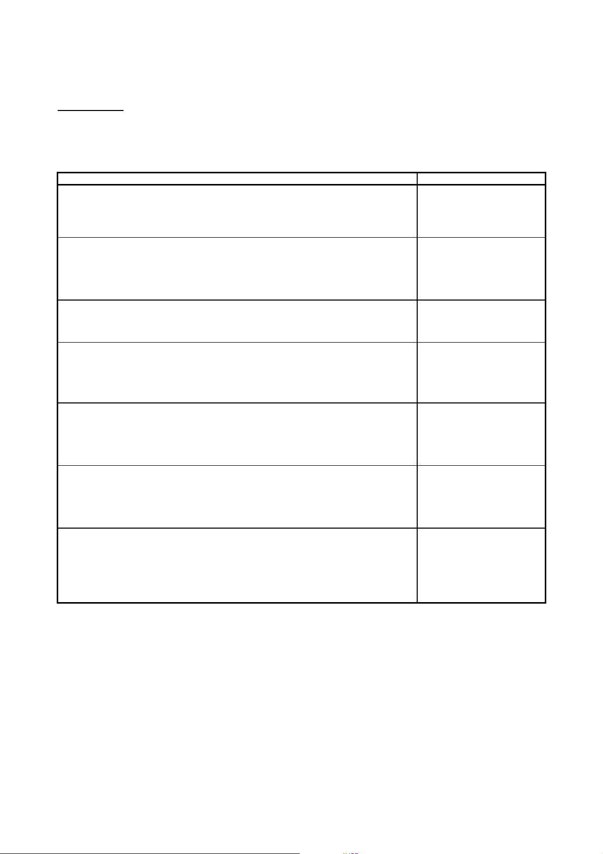
About Manuals
The following manuals related to this product are available. Obtain the manuals as
required the according to this table.
• Related manual
Manual name Manual number (Model code)
GT Works Version5/GT Designer Version5 Operating Manual (Start up M anual)
Describes how to install GT Works Version5/GT Designer Version5 into a personal computer and
how to browse the online manuals.
(Found in the packing of the GT Works Version5/GT Designer Version5)
GT Works Version5/GT Designer Version5 Reference Manual
Deals with the system configuration of GT Works Version5/GT Designer Version5, the screen
makeup of the GT Designer, the general description of various monitoring functions, the procedure
for displaying the monitor screen on the GOT, and how to use the help function.
(Available as option)
IB-0800143
(13JU06)
SH-080117
(13JF95)
GT Simulator Version5 Operating Manual
Explains the system configuration, screen makeup and using methods of GT Simulator.
(Available as option)
GOT-A900 Series User’s Manual (GT Works Version5/GT D esigner Version5
compatible Connection System Manual)
Gives the specifications, system configuration, setting method and connection diagram of each
connection form available for the GOT-A900 series.
(Available as option)
A985GOT/A975GOT/A970GOT/A960GOT User’s Manual
Explains the specifications, general system configuration, component devices, part names, option
unit loading methods, installation and wiring methods, maintenance and inspection methods, and
error codes of A985GOT/A975GOT/A970GOT/A960GOT unit.
(Available as option)
A950GOT/A951GOT/A953GOT/A956GOT User’s Manual
Explains the specifications, general system configuration, component devices, part names, option
unit loading methods, installation and wiring methods, maintenance and inspection methods, and
error codes of A950GOT/A951GOT/A953GOT/A956GOT unit.
(Available as option)
GOT-A900 Series Operating Manual (GT Works Version5/GT Designer Version5
compatible Extended • Option Functions Manual)
Provides the specifications of the utility, system monitoring, ladder monitoring, special function unit
monitoring, network monitoring functions and list editor functions available for the GOT-A900 series
and how to operate the dedicated monitor screen.
(Available as option)
SH-080120
(13JU09)
SH-080119
(13JR20)
SH-4005
(13JL70)
SH-080018
(13JL92)
SH-080118
(13JU08)
A - 8 A - 8
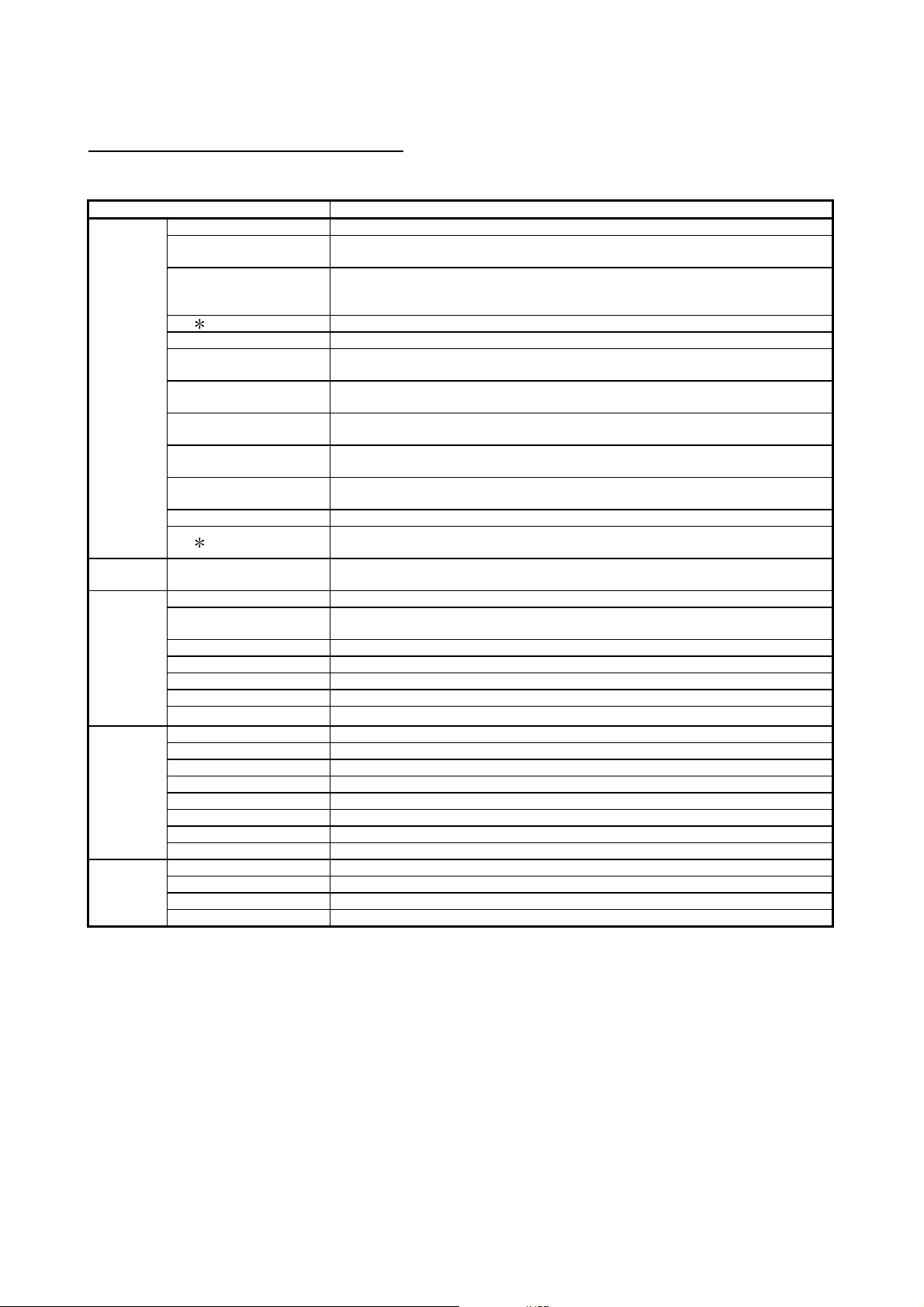
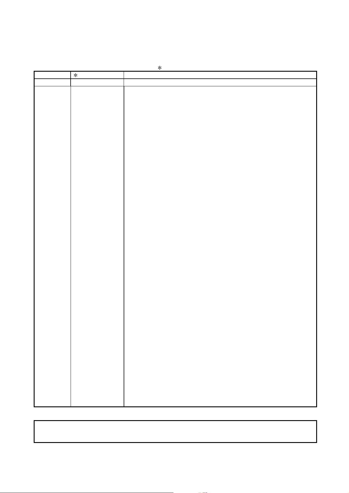
Abbreviations and generic terms in this manual
Abbreviations and generic terms used in this manual are described as follows:
Abbreviations and generic terms Description
A985GOT Generic term of A985GOT-TBA, A985GOT-TBD and A985GOT-TBA-EU
Generic term of A975GOT-TBA-B, A975GOT-TBD-B, A975GOT-TBA, A975GOT-TBD and
A975GOT-TBA-EU
Generic term of A970GOT-TBA-B A970GOT-TBD-B, A970GOT-TBA, A970GOT-TBD,
A970GOT-SBA, A970GOT-SBD, A970GOT-LBA, A970GOT-LBD, A970GOT-TBA-EU and
A970GOT-SBA-EU
Generic term of A956GOT-TBD, A956GOT-SBD, A956GOT-LBD, A956GOT-TBD-M3,
A956GOT-SBD-M3 and A956GOT-LBD-M3
Generic term of A953GOT-TBD, A953GOT-SBD, A953GOT-LBD, A953GOT-TBD-M3,
A953GOT-SBD-M3 and A953GOT-LBD-M3
Generic term of A951GOT-TBD, A951GOT-SBD, A951GOT-LBD, A951GOT-TBD-M3,
A951GOT-SBD-M3 and A951GOT-LBD-M3
Generic term of A951GOT-QTBD, A951GOT-QSBD, A951GOT-QLBD, A951GOT-QTBD-M3,
A951GOT-QSBD-M3 and A951GOT-QLBD-M3
Generic term of A950GOT-TBD, A950GOT-SBD, A950GOT-LBD, A950GOT-TBD-M3,
A950GOT-SBD-M3 and A950GOT-LBD-M3
Generic term of A956GOT, A953GOT, A951GOT, A951GOT-Q, A950GOT and A950 handy
GOT
Generic term of SW5D5C-GOTR-PACKE software package and SW5D5C-GOTR-PACKEV
software package
Abbreviation of GT Manager data editing software for GOT900
GOT
Communication board
Software
CPU
Others
A975GOT
A970GOT
A97 GOT Generic term of A975GOT and A970GOT
A960GOT Generic term of A960GOT-EBA, A960GOT-EBD and A960GOT-EBA-EU
A956GOT
A953GOT
A951GOT
A951GOT-Q
A950GOT
A950 handy GOT Generic term of A953GOT-SBD-M3-H and A953GOT-LBD-M3-H
GOT
A95
Bus connection board Generic term of A9GT-QBUSS, A9GT-QBUS2S, A9GT-BUSS and A9GT-BUS2S
GT Works Version5 SW5D5C-GTWORKS-E software package
GT Designer Version5
GT Designer Abbreviation of image creation software GT Designer for GOT900
GT Simulator Abbreviation of GT Simulator screen simulator GOT900
GT Converter Abbreviation of data conversion software GT Converter for GOT900
GT Debugger Abbreviation of debugging software GT Debugger
GT Manager
AnUCPU Generic term of A2UCPU, A2UCPU-S1, A3UCPU and A4UCPU CPU units
AnACPU Generic term of A2ACPU, A2ACPU-S1 and A3ACPU CPU units
AnNCPU Generic term of A1NCPU, A2NCPU, A2NCPU-S1 and A3NCPU CPU units
ACPU (Large Type) Generic term of AnUCPU, AnACPU and AnNCPU CPU units
A2US(H)CPU Generic term of A2USCPU, A2USCPU-S1 and A2USHCPU-S1 CPU units
AnS(H)CPU Generic term of A1SCPU, A1SHCPU, A2SCPU and A2SHCPU CPU units
A1SJ(H)CPU Generic term of A1SJCPU-S3 and A1SJHCPU CPU units
ACPU (Small Type) Generic term of A2US(H)CP U, AnS(H)CPU and A1SJ(H)CPU CPU units
Memory abbreviation of mmory (flash memory) in the GOT
OS Abreviation of GOT system software
Object Setting data for dynamic image
Personal Computer Personal computer where the corresponding software package is installed
A - 9 A - 9
1 FUNDAMENTAL KNOWLEDGE
CHAPTER1 FUNDAMENTAL KNOWLEDGE
MELSOFT
1
1.1 About GOT
This manual describes procedures for creating a simple screen and monitoring with the
GOT for learning basic operations.
If using the GOT for the first time, read this manual to become familiar with operation of
the GOT and the GT Designer.
POINT
The screen data and sequence programs created in Chapters 3 and 4 of this
manual are packed with GT Designer.
Use them as required to check settings, for example.
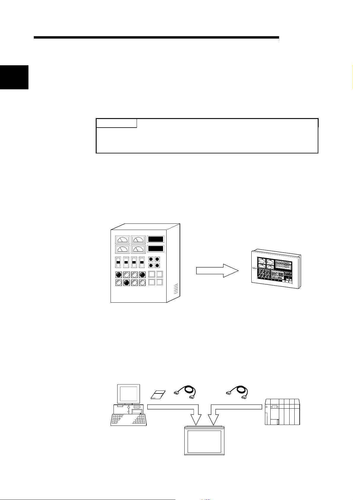
(1) What is the GOT?
The GOT can be used as an electronic operator panel which has achieved on its
monitor screen th e sw itch ope rat io n, la mp in di cat io n, da t a di splay , messa ge
display and other operations which were previously performed on an operator
panel.
Space saving
Cost reduction
(2) About monitor screen data to be display ed on the GOT
The monitor screen data to be displayed on the GOT are created on a personal
computer using the dedicated software (GT Designer).
You can perform the corresponding functions of the GOT by pasting display
frame figures called switch figure, lamp figure, numerical display and other
objects to create screens on GT Designer, and setting PLC CPU device memory
(bit, word) driven operating functions to the pasted objects.
The monitor screen data created are transferred to the GOT through an RS-232C
cable or PC card (memory card).
PC card
RS-232C cable Any of various connection cables
ConnectionScreen data transfer
Personal computer
GOT
1 - 1 1 - 1
PLC CPU
1 FUNDAMENTAL KNOWLEDGE
1.2 About GOT Operations
MELSOFT
This section briefly explains what operations the GOT will perform when it is connected
with the PLC CPU.
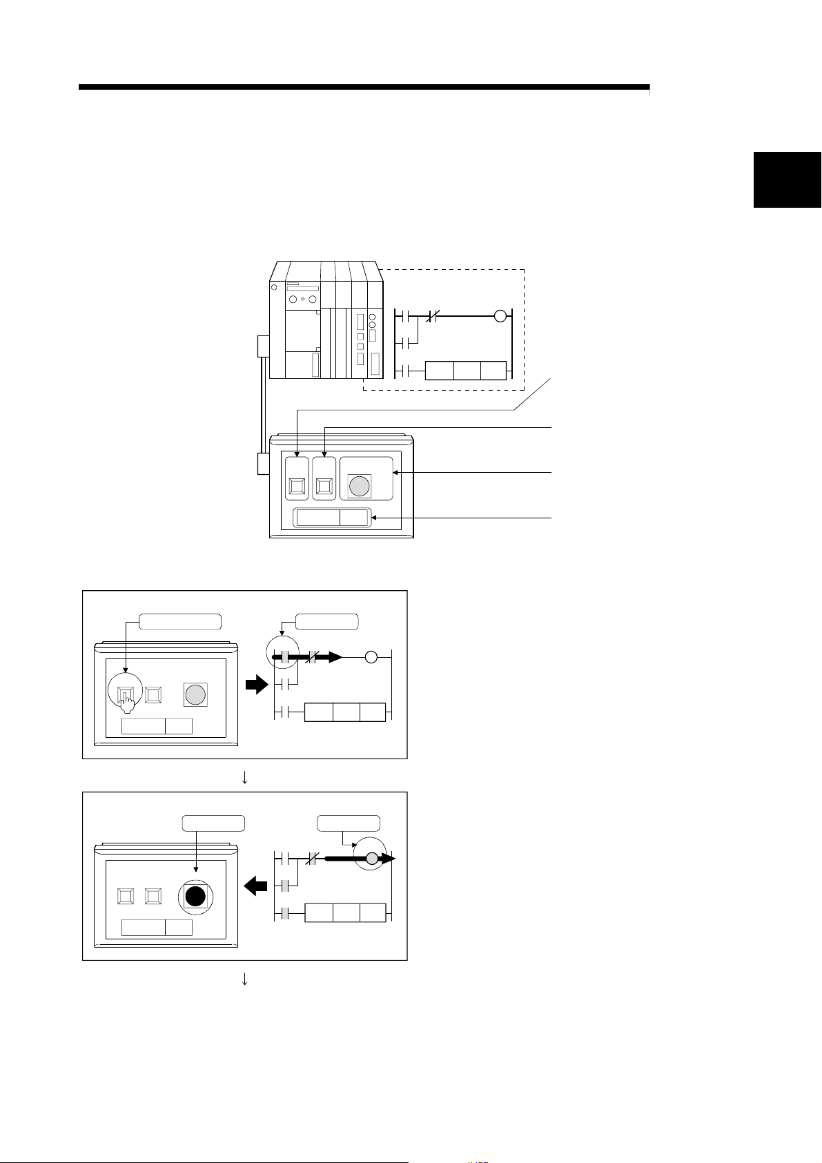
(1) System example
PLC CPU
Sequence program
M0
M1 Y10
Y10
<GOT settings made to figures>
Touch key setting
Bit momentary
Write device: M0
Touch key setting
Bit momentary
Write device: M1
Lamp display setting
Bit
Read device: Y10
Numerical display setting
Read device: D10, unsigned BIN
Indication: Unsigned decimal
Bus connection cable
GOT
Run Run lampStop
Data 1
123
Y10
K123MOV D10
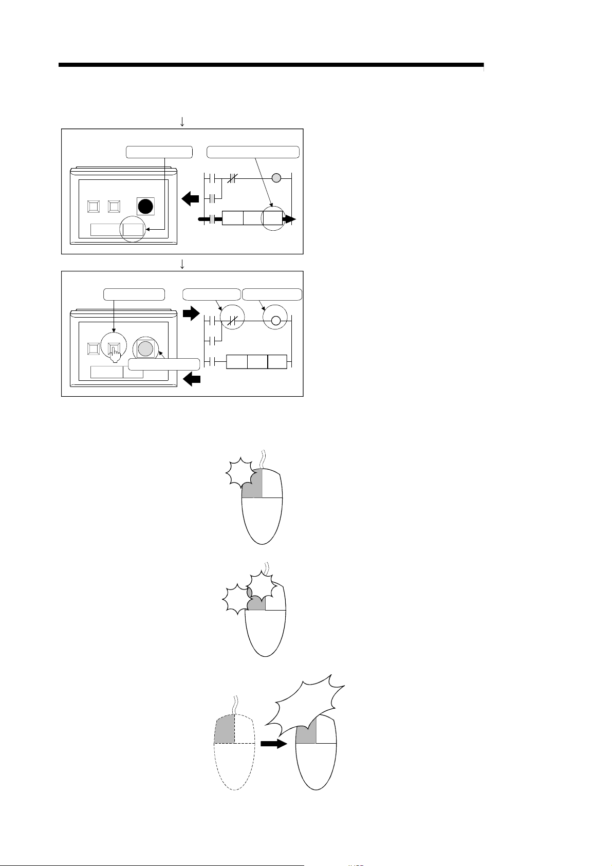
(2) Operation explanation
1
(GOT) (PLC CPU )
Turns ON.Touch.
M0
M1 Y10
Y10
Y10
(PLC CPU )
M0
Y10
Y10
M1 Y10
(GOT)
Run
Run
Data
Data
Stop
Stop
Run lamp
0
Turns ON. Turns ON.
Run lamp
0
1) While the "Run" touch key of the GOT is touched,
the bit device "M0 " i s ON.
K123MOV D10
2) When the bit device "M0" turns ON, the bit device
"Y10" turns ON.
An ON figure also appears as the GOT's lamp
display where the monitor device is preset to the bit
device "Y10".
K123MOV D10
(To the followin g pa ge )
1 - 2 1 - 2
1 FUNDAMENTAL KNOWLEDGE
(From the previous page)
MELSOFT
(GOT)
(GOT)
Run
Stop
Data 123
Run
Stop
Data 123
"123" appears.
Run lamp
Touch.
Run lamp
Display tur ns OFF.
(PLC CPU )
"123" is stored into D10.
M0
M1
Y10
Y10
(PLC CPU )
M1 turns ON.
M0
M1 Y10
Y10
Y10
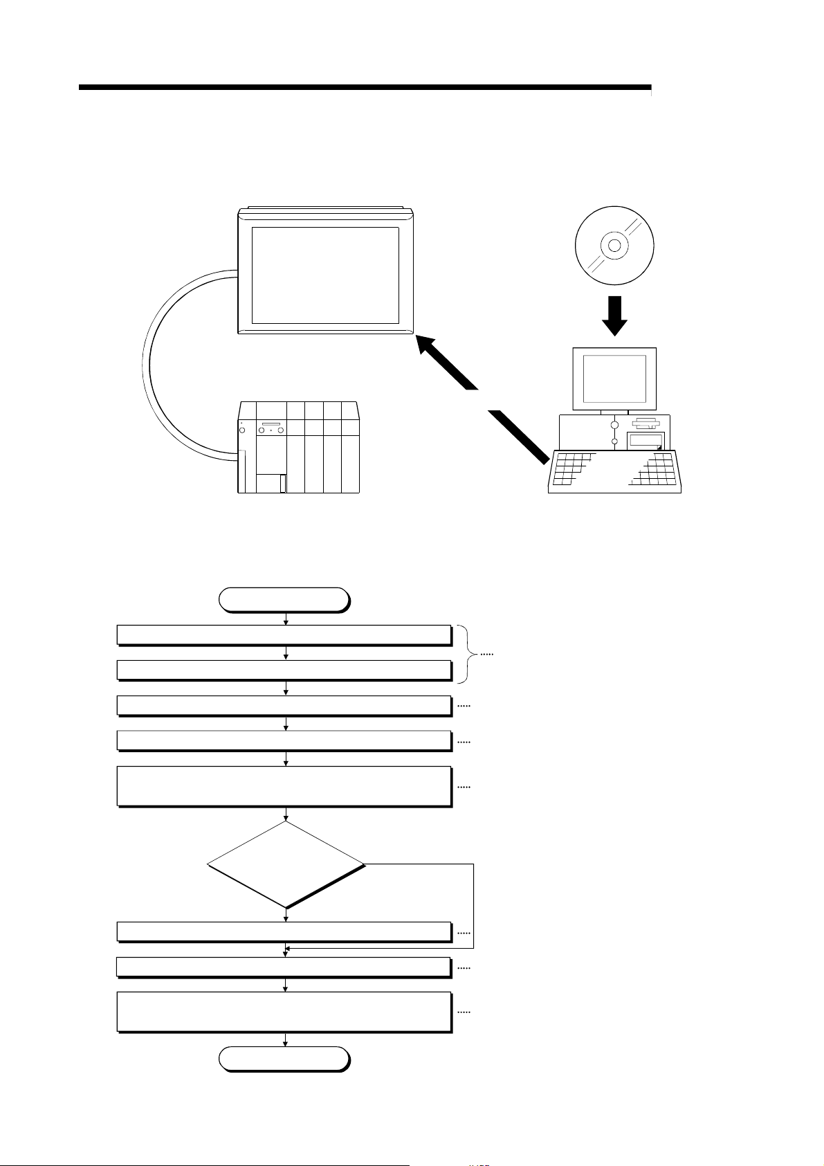
1.3 Mouse Usage and Operations
Describes basic operations of the mouse.
(1) Click
Y10
K123MOV D10
Y10 turns OFF.
K123MOV D10
Click
3) Since the bit device "M0" is ON, "123" is stored into
the word device "D10".
"123" also appears as the GOT's numerical display
where the monitor device is preset to the word
device "D10".
4) While the "Stop" touch key of the GOT is touched,
the bit device "M1" of the PLC CPU is ON.
Since the bit device "Y10" of the PLC CPU turns
OFF, the lamp display of the GOT turns OFF.
Press the left button of the mouse once, then
release without moving the mouse.
This is the most common operation.
Using the right button to perform this operation is
called "right-click".
(2) Double click
Press the left button of the mouse twice quickly
Click
Click
without moving the mouse. This operation is for
the left button only.
(3) Drag
Move the mouse while pressing the
left button.
Move the mouse
while the button
is pressed.
1 - 3 1 - 3
Using the right button to perform this
operation is called "right-drag".
1 FUNDAMENTAL KNOWLEDGE
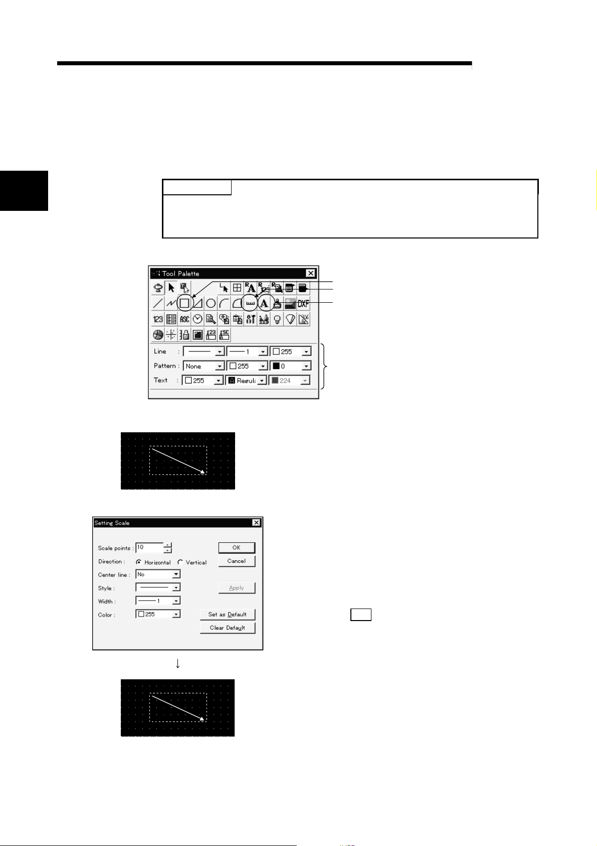
1.4 System Configuration Used in the M anual
A975GOT
Bus connection
Data tr ansfer
GT Works Version5
GT Designer Version5
Install
or
MELSOFT
PLC CPU (ACPU)
1.5 Procedures for Use of GOT
Describes the procedures from installation of the GT Designer to monitoring with the
GOT.
Start
Install the GT Designer.
Start the GT Designer.
Carry out common setting. Refer to 3.1
Prepare the user screen data.
Connect the GOT and the personal computer with RS-232C,
and turn ON the GOT.
Using the GOT
for the first time?
Personal computer
GT Works Version5/GT Designer Version5
Operating Manual (Start up Manual)
Refer to Chapter 3 and Chapter 4
Refer to 5.1
No
Yes
Install the OS and the communication driver.
Transfer the user screen data.
Connect to the PLC, and start monitoring.
(Turn OFF the GOT, then turn it ON again.)
End
Refer to 5.2
Refer to 5.3
Refer to 5.4 and 5.5
1 - 4 1 - 4
2 SETTING FIGURES AND OBJECTS
CAHPTER2 SETTING FIGURES AND OBJECTS
2.1 Drawing a Figure
Describes how to draw a figure.
MELSOFT
2
POINT
This chapter deals with only the drawing and editing of figures used in this manual.
For the drawing and editing of other figures, refer to the help function of GT
Designer.
When drawing a figure, click the icon of the figure you want to draw.
Click when drawing a rectangle.
Click when drawing a scale.
Click when entering a text.
When setting the attributes of a
figure or text, click the list box to
choose the attributes.
For details, refer to the GT Works
Version5/GT Designer Version5
Reference Manual.
(1) When drawing a rectangle
1)
2)
3)
1) Click the left mouse button at the start point of the
rectangle.
2) Drag the cursor to the end point.
3) Release the left mouse button. A rectangle appears.
(2) When drawing a scale
1) As the scale setting dialog box appears, make
settings.
Scale points: Se t t he numbe r of sca le poi nt s.
Direction: Choo se t he scale di rect ion.
Center line: Specify whether a line is drawn in the
scale center or not.
2) Click the OK
3) Press the left mouse button at the starting point of
3)
4)
5)
drawing the scale.
4) Drag the cursor to the end point.
5) Release the left mouse button. The scale appears.
2 - 1 2 - 1
button.
2 SETTING FIGURES AND OBJECTS
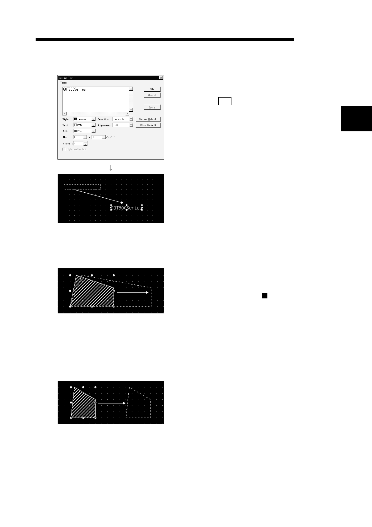
(3) When entering a text
MELSOFT
1) As the text/figure setting dialog box appears, enter a
text.
3)
2.2 Editing a Figure or Object (1) Resizing a figure or object
The following example enlarges a figure.
2) Click the OK
button.
2
3) A frame of display range appears at the upper-left of
the screen.
Move the frame to the desired position.
4)
4) Click the mouse button.
The character string appears.
1) Select the figure to enlarge.
2) Press the left mouse button at the handle of the
2) 3)
selected figure or object (
enlarge, then drag it.
3) Release the left mouse button. The figure or object
is resized.
• Holding down th e Shi ft key and changing the size
resizes the figu r e at eq ua l r atio s .
• Holding down th e C t rl key and changing the siz e
resizes the figure relative to the center.
(2) Copying a figure or object
The following example copies a figure.
1) Choose the fig u re to be copi ed .
2) Hold down the "Ctrl" button of the keyboard and drag
2) 3)
the figure .
3) Release the left button of the mouse at the position
you want to copy. This copies the figure.
) in the directio n to
2 - 2 2 - 2
3 CREATING SCREENS
CHAPTER3 CREATING SCREENS
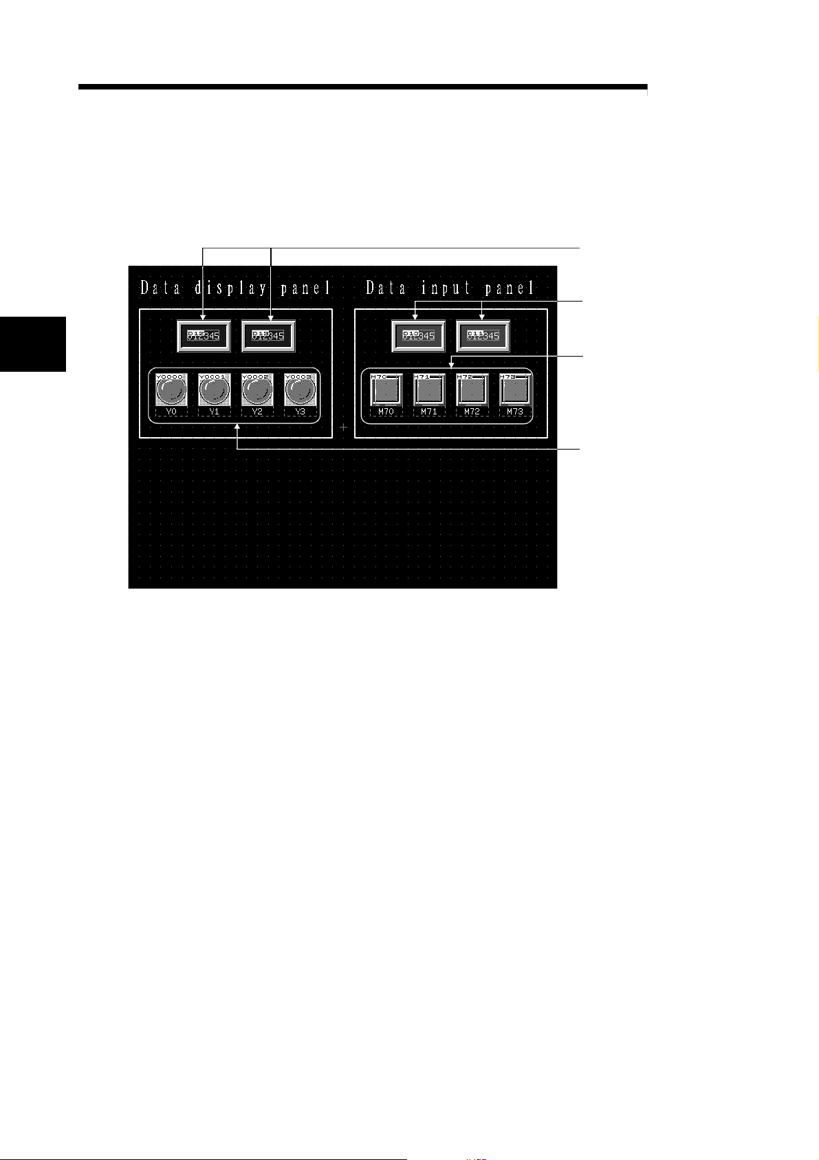
3.1 Creating a Screen like This
In this chapter, a screen as shown below is created.
MELSOFT
Numerical
display function
Numerical
input function
3
Touch key function
Lamp display function
3 - 1 3 - 1
 Loading...