


GT16 User's Manual (Hardware)

SAFETY PRECAUTIONS
WARNING
Indicates that incorrect handling may cause hazardous
conditions, resulting in death or severe injury.
CAUTION
Indicates that incorrect handling may cause hazardous
conditions, resulting in medium or slight personal injury or
physical damage.
(Always read these precautions before using this equipment.)
Before using this product, please read this manual and the relevant manuals introduced in this manual
carefully and pay full attention to safety to handle the product correctly.
The precautions given in this manual are concerned with this product.
In this manual, the safety precautions are ranked as "WARNING" and "CAUTION".
Note that the caution level may lead to a serious accident according to the circumstances. Always
follow the instructions of both levels because they are important to personal safety.
Please save this manual to make it accessible when required and always forward it to the end user.
[DESIGN PRECAUTIONS]
WARNING
Some failures of the GOT, communication unit or cable may keep the outputs on or off.
Some failures of a touch panel may cause malfunction of the input objects such as a touch switch.
An external monitoring circuit should be provided to check for output signals which may lead to a
serious accident.
Not doing so can cause an accident due to false output or malfunction.
If a communication fault (including cable disconnection) occurs during monitoring on the GOT,
communication between the GOT and PLC CPU is suspended and the GOT becomes inoperative.
For bus connection: The CPU becomes faulty and the GOT becomes inoperative.
For other than bus connection: The GOT becomes inoperative.
A system where the GOT is used should be configured to perform any significant operation to the
system by using the switches of a device other than the GOT on the assumption that a GOT
communication fault will occur.
Not doing so can cause an accident due to false output or malfunction.
Do not use the GOT as the warning device that may cause a serious accident.
An independent and redundant hardware or mechanical interlock is required to configure the device
that displays and outputs serious warning.
Failure to observe this instruction may result in an accident due to incorrect output or malfunction.
A - 1
[DESIGN PRECAUTIONS]
WARNING
Incorrect operation of the touch switch(s) may lead to a serious accident if the GOT backlight is gone
out.
When the GOT backlight goes out, although the POWER LED blinks (green/orange) and the display
section dims, the input of the touch switch(s) remains active.
This may confuse an operator in thinking that the GOT is in "screensaver" mode, who then tries to
release the GOT from this mode by touching the display section, which may cause a touch switch to
operate.
Note that the following occurs on the GOT when the backlight goes out.
• GT1655-V: The POWER LED blinks (green/orange) and the monitor screen appears blank.
• Models other than GT1655-V: The POWER LED blinks (green/orange) and the monitor screen
appears dimmed.
The display section of the GT16 is an analog-resistive type touch panel.
If you touch the display section simultaneously in 2 points or more, the switch that is located around
the center of the touched point, if any, may operate.
Do not touch the display section in 2 points or more simultaneously.
Doing so may cause an accident due to incorrect output or malfunction.
When programs or parameters of the controller (such as a PLC) that is monitored by the GOT are
changed,be sure to reset the GOT or shut off the power of the GOT at the same time.
Not doing so can cause an accident due to false output or malfunction.
CAUTION
Do not bundle the control and communication cables with main-circuit, power or other wiring.
Run the above cables separately from such wiring and keep them a minimum of 100mm (3.94in.)
apart.Not doing so noise can cause a malfunction.
Do not press the GOT display section with a pointed material as a pen or driver.
Doing so can result in a damage or failure of the display section.
When the GOT is connected to the Ethernet network, the available IP address is restricted according
to the system configuration.
• When multiple GOTs are connected to the Ethernet network:
Do not set the IP address (192.168.0.18) for the GOTs and the controllers in the network.
• When a single GOT is connected to the Ethernet network:
Do not set the IP address (192.168.0.18) for the controllers except the GOT in the network.
Doing so can cause the IP address duplication. The duplication can negatively affect the
communication of the device with the IP address (192.168.0.18).
The operation at the IP address duplication depends on the devices and the system.
Turn on the controllers and the network devices to be ready for communication before they
communicate with the GOT.
Failure to do so can cause a communication error on the GOT.
A - 2
[MOUNTING PRECAUTIONS]
WARNING
Be sure to shut off all phases of the external power supply used by the system before mounting or
removing the GOT main unit to/from the panel.
Not doing so can cause the unit to fail or malfunction.
Be sure to shut off all phases of the external power supply used by the system before mounting or
removing the communication unit, printer unit or option function board onto/from the GOT.
Not doing so can cause the unit to fail or malfunction.
When installing the option function board, wear an earth band etc. to avoid the static electricity.
Not doing so can cause a unit corruption.
CAUTION
Use the GOT in the environment that satisfies the general specifications described in this manual.
Not doing so can cause an electric shock, fire, malfunction or product damage or deterioration.
When mounting the GOT to the control panel, tighten the mounting screws in the specified torque
range (0.36 to 0.48 N•m) with a Phillips-head screwdriver No.2.
Undertightening can cause the GOT to drop, short circuit or malfunction.
Overtightening can cause a drop, short circuit or malfunction due to the damage of the screws or the
GOT.
When loading the communication unit to the GOT, fit it to the connection interface of the GOT and
tighten the mounting screws in the specified torque range (0.36 to 0.48 N•m) with a Phillips-head
screwdriver No.2.
Undertightening can cause the GOT to drop, short circuit or malfunction.
Overtightening can cause a drop, failure or malfunction due to the damage of the screws or unit.
When mounting the option function board onto the GOT, connect it to the corresponding connector
securely and tighten the mounting screws within the specified torque range (0.25 to 0.35 N•m) with a
Phillips-head screwdriver No.1.
Undertightening can cause malfunction due to poor contact.
Overtightening can cause malfunction due to screw or unit damage.
When inserting a CF card into the GOT, push it into the CF card interface of GOT until the CF card
eject button will pop out.
If not properly inserted, a bad connection may cause a malfunction.
When inserting/removing a CF card into/from the GOT, turn the CF card access switch off in
advance.
Failure to do so may corrupt data within the CF card.
When removing a CF card from the GOT, make sure to support the CF card by hand, as it may pop
out.
Failure to do so may cause the CF card to drop from the GOT and break.
A - 3
[MOUNTING PRECAUTIONS]
CAUTION
When installing a USB memory to the GOT, make sure to install the USB memory to the USB
interface firmly.
Failure to do so may cause a malfunction due to poor contact.
Before removing the USB memory from the GOT, operate the utility screen for removal. After the
successful completion dialog box is displayed, remove the memory by hand carefully.
Failure to do so may cause the USB memory to drop, resulting in a damage or failure of the memory.
For closing the USB environmental protection cover, fix the cover by pushing the mark on the
latch firmly to comply with the protective structure.
Remove the protective film of the GOT.
When the user continues using the GOT with the protective film, the film may not be removed.
Operate and store the GOT in environments without direct sunlight, high temperature, dust, humidity,
and vibrations.
When using the GOT in the environment of oil or chemicals, use the protective cover for oil.
Failure to do so may cause failure or malfunction due to the oil or chemical entering into the GOT.
[WIRING PRECAUTIONS]
WARNING
Be sure to shut off all phases of the external power supply used by the system before wiring.
Failure to do so may result in an electric shock, product damage or malfunctions.
CAUTION
Make sure to ground the FG terminal, LG terminal, and functional ground terminal of the GOT power
supply section with a ground resistance of 100Ω or less solely for the GOT.
Not doing so may cause an electric shock or malfunction.
When tightening the terminal screws, use a Phillips-head screwdriver No.2.
Terminal screws which are not to be used must be tightened always at torque 0.5 to 0.8 N
Otherwise there will be a danger of short circuit against the solderless terminals.
Use applicable solderless terminals and tighten them with the specified torque.
If any solderless spade terminal is used, it may be disconnected when the terminal screw comes
loose, resulting in failure.
·m.
Correctly wire the GOT power supply section after confirming the rated voltage and terminal
arrangement of the product.
Not doing so can cause a fire or failure.
A - 4
[WIRING PRECAUTIONS]
CAUTION
Tighten the terminal screws of the GOT power supply section in the specified torque range (0.5 to
0.8 N.m).
Undertightening can cause a short circuit or malfunction.
Overtightening can cause a short circuit or malfunction due to the damage of the screws or the GOT.
Exercise care to avoid foreign matter such as chips and wire offcuts entering the GOT. Not doing so
can cause a fire, failure or malfunction.
The module has an ingress prevention label on its top to prevent foreign matter, such as wire offcuts,
from entering the module during wiring.
Do not peel this label during wiring.
Before starting system operation, be sure to peel this label because of heat dissipation.
Plug the communication cable into the connector of the connected unit and tighten the mounting and
terminal screws in the specified torque range.
Undertightening can cause a short circuit or malfunction.
Overtightening can cause a short circuit or malfunction due to the damage of the screws or unit.
Plug the QnA/ACPU/Motion controller (A series) bus connection cable by inserting it into the
connector of the connected unit until it "clicks".
After plugging, check that it has been inserted snugly.
Not doing so can cause a malfunction due to a contact fault.
[TEST OPERATION PRECAUTIONS]
WARNING
Before performing the test operations of the user creation monitor screen (such as turning ON or
OFF bit device, changing the word device current value, changing the settings or current values of
the timer or counter, and changing the buffer memory current value), read through the manual
carefully and make yourself familiar with the operation method.
During test operation, never change the data of the devices which are used to perform significant
operation for the system.
False output or malfunction can cause an accident.
[STARTUP/MAINTENANCE PRECAUTIONS]
WARNING
When power is on, do not touch the terminals.
Doing so can cause an electric shock or malfunction.
A - 5

[STARTUP/MAINTENANCE PRECAUTIONS]
WARNING
Correctly connect the battery connector.
Do not perform the following actions to the battery.
• Charging, disassembling, heating, short-circuiting, or soldering the battery, or throwing it into the
fire
Doing so will cause the battery to produce heat, explode, or ignite, resulting in injuly and fire.
Before starting cleaning or terminal screw retightening, always switch off the power externally in all
phases.
Not switching the power off in all phases can cause a unit failure or malfunction.
Undertightening can cause a short circuit or malfunction.
Overtightening can cause a short circuit or malfunction due to the damage of the screws or unit.
CAUTION
Do not disassemble or modify this unit.
Doing so can cause a failure, malfunction, injury, or fire.
Do not touch the conductive and electronic parts of the unit directly.
Doing so can cause a unit malfunction or failure.
The cables connected to the unit must be run in ducts or clamped.
Not doing so can cause the unit or cable to be damaged due to the dangling, motion or accidental
pulling of the cables or can cause a malfunction due to a cable connection fault.
When unplugging the cable connected to the unit, do not hold and pull the cable portion.
Doing so can cause the unit or cable to be damaged or can cause a malfunction due to a cable
connection fault.
Do not drop the module or subject it to strong shock.
A module damage may result.
Do not drop or give an impact to the battery mounted to the unit.
Doing so may damage the battery, causing the battery fluid to leak inside the battery.
If the battery is dropped or given an impact, dispose of it without using.
Before touching the unit, always touch grounded metal, etc. to discharge static electricity from
human body, etc.
Not doing so can cause the unit to fail or malfunction.
Replace battery with GT15-BAT or GT11-50BAT by Mitsubishi electric Co. only.
Use of another battery may present a risk of fire or explosion.
Dispose of used battery promptly.
Keep away from children. Do not disassemble and do not dispose of in fire.
A - 6
[TOUCH PANEL PRECAUTIONS]
CAUTION
For the analog-resistive film type touch panels, normally the adjustment is not required.
However, the difference between a touched position and the object position may occur as the period
of use elapses. When any difference between a touched position and the object position occurs,
execute the touch panel calibration.
When any difference between a touched position and the object position occurs, other objects may
be activated. This may cause an unexpected operation due to incorrect output or malfunction.
[COLD CATHODE TUBE BACKLIGHT REPLACEMENT
PRECAUTIONS]
WARNING
Be sure to shut off all phases of the external power supply of the GOT (and the PLC CPU in the case
of a bus topology) and remove the GOT from the control panel before replacing the backlight (when
using the GOT with the backlight replaceable by the user).
Not doing so can cause an electric shock.
Replacing a backlight without removing the GOT from the control panel can cause the backlight to
drop, resulting in an injury.
CAUTION
Wear gloves for the backlight replacement when using the GOT with the backlight replaceable by the
user.
Not doing so can cause an injury.
Before replacing a backlight, allow 5 minutes or more after turning off the GOT when using the GOT
with the backlight replaceable by the user.
Not doing so can cause a burn from heat of the backlight.
[DISPOSAL PRECAUTIONS]
CAUTION
When disposing of this product, treat it as industrial waste.
When disposing of batteries, separate them from other wastes according to the local regulations.
(For details of the battery directive in EU member states, refer to Handling of Batteries and Devices
with Built-in Batteries in EU Member States.)
A - 7

[TRANSPORTATION PRECAUTIONS]
CAUTION
When transporting lithium batteries, make sure to treat them based on the transport regulations.
(Refer to Appendix 3 for details of the regurated models.)
Make sure to transport the GOT main unit and/or relevant unit(s) in the manner they will not be
exposed to the impact exceeding the impact resistance described in the general specifications of this
manual, as they are precision devices.
Failure to do so may cause the unit to fail.
Check if the unit operates correctly after transportation.
A - 8

INTRODUCTION
Thank you for choosing the Mitsubishi Graphic Operation Terminal.
Before using the equipment, please read this manual carefully to use the equipment to its optimum.
CONTENTS
SAFETY PRECAUTIONS .........................................................................................................................A - 1
INTRODUCTION ......................................................................................................................................A - 9
CONTENTS ..............................................................................................................................................A - 9
ABOUT MANUALS .................................................................................................................................A - 13
QUICK REFERENCE ............................................................................................................................. A - 16
ABBREVIATIONS AND GENERIC TERMS ...........................................................................................A - 18
HOW TO USE THIS MANUAL................................................................................................................A - 23
PACKING LIST .......................................................................................................................................A - 24
1. OVERVIEW
1.1 Features........................................................................................................................................... 1 - 2
1.2 Rough Pre-operation Procedure...................................................................................................... 1 - 3
2. SYSTEM CONFIGURATION
2.1 Overall Configuration ....................................................................................................................... 2 - 1
2.2 Component List................................................................................................................................ 2 - 2
2.2.1 GOT...................................................................................................................................... 2 - 4
2.2.2 Option ................................................................................................................................... 2 - 5
3. SPECIFICATIONS
3.1 General Specifications..................................................................................................................... 3 - 1
3.2 Performance Specifications ............................................................................................................. 3 - 2
3.2.1 GT1695M-X .......................................................................................................................... 3 - 2
3.2.2 GT1685M-S .......................................................................................................................... 3 - 5
3.2.3 GT1675M-S, GT1675M-V, GT1675-VN, GT1672-VN .......................................................... 3 - 8
3.2.4 GT1665M-S, GT1665M-V, GT1662-VN ............................................................................. 3 - 11
3.2.5 GT1655-V ........................................................................................................................... 3 - 14
3.3 Power Supply Specifications ......................................................................................................... 3 - 17
3.3.1 For GOTs powered from the 100 to 240VAC power supply ............................................... 3 - 17
3.3.2 For GOTs powered from the 24VDC power supply ............................................................ 3 - 18
3.4 Battery Specifications .................................................................................................................... 3 - 19
4. PART NAME AND SETTINGS
4.1 Part Names and Settings of the GT1695......................................................................................... 4 - 1
4.2 Part Names and Settings of the GT1685......................................................................................... 4 - 3
4.3 Part Names and Settings of the GT1675, GT1672.......................................................................... 4 - 5
4.4 Part Names and Settings of the GT1665, GT1662.......................................................................... 4 - 7
A - 9

4.5 Part Names and Settings of the GT1655 ......................................................................................... 4 - 9
5. EMC AND LOW VOLTAGEDIRECTIVE
5.1 Requirements to Meet EMC Directive ............................................................................................. 5 - 1
5.1.1 EMC directive ....................................................................................................................... 5 - 2
5.1.2 Control panel ........................................................................................................................ 5 - 3
5.1.3 Noise filter (power supply line filter) ...................................................................................... 5 - 4
5.2 Requirements for Conpliance with the Low Voltage Directive ......................................................... 5 - 5
5.2.1 Standard subject to GOT ...................................................................................................... 5 - 5
5.2.2 Power supply ........................................................................................................................ 5 - 5
5.2.3 Control panel ........................................................................................................................ 5 - 6
5.2.4 Grounding ............................................................................................................................. 5 - 6
5.2.5 External wiring ...................................................................................................................... 5 - 6
5.3 EMC Directive-Compliant System Configuration ............................................................................. 5 - 7
5.3.1 GOT ...................................................................................................................................... 5 - 7
5.3.2 Connection method............................................................................................................... 5 - 8
5.3.3 When the communication unit is used .................................................................................. 5 - 9
5.3.4 When the option unit is used .............................................................................................. 5 - 11
5.3.5 When the option is used ..................................................................................................... 5 - 11
5.3.6 Cables................................................................................................................................. 5 - 12
5.4 Precautions for Wiring/Connecting the EMC Directive-Compliant Product.................................... 5 - 13
5.4.1 Power and ground wires wiring method.............................................................................. 5 - 13
5.4.2 Processing connection cables ............................................................................................ 5 - 15
5.4.3 Grounding the cable ........................................................................................................... 5 - 21
6. INSTALLATION
6.1 Control Panel Inside Dimensions for Mounting GOT ....................................................................... 6 - 1
6.2 Panel Cutting Dimensions ............................................................................................................... 6 - 2
6.3 Mounting Position ............................................................................................................................ 6 - 3
6.4 Control Panel Inside Temperature and Mounting Angle ................................................................ 6 - 10
6.5 Installation Procedure .................................................................................................................... 6 - 10
7. WIRING
7.1 Power Supply Wiring ....................................................................................................................... 7 - 2
7.2 Wiring to GOT Power Section.......................................................................................................... 7 - 3
7.3 Grounding ........................................................................................................................................ 7 - 4
7.3.1 Grounding the GOT .............................................................................................................. 7 - 4
7.3.2 Wiring-related malfunction causes and the measures examples ......................................... 7 - 6
7.4 Panel Inside Wiring, Panel Outside Wiring ...................................................................................... 7 - 8
7.4.1 Panel inside wiring................................................................................................................ 7 - 8
7.4.2 Panel outside wiring.............................................................................................................. 7 - 8
7.5 Attaching Surge Suppressor for Control Equipment ........................................................................ 7 - 9
7.6 Grounding Extension Units ............................................................................................................ 7 - 10
7.6.1 Wiring FG cable of bus connection cable ........................................................................... 7 - 10
7.6.2 Wiring FG cable of CF card extension unit connection cable ............................................. 7 - 11
A - 10

8. OPTION
8.1 Communication Unit ........................................................................................................................ 8 - 1
8.1.1 Applicable communication unit ............................................................................................. 8 - 1
8.1.2 Installing multiple extension units in layers........................................................................... 8 - 2
8.2 Option Unit....................................................................................................................................... 8 - 4
8.2.1 Applicable option unit ........................................................................................................... 8 - 4
8.3 Option .............................................................................................................................................. 8 - 5
8.3.1 Applicable option .................................................................................................................. 8 - 5
8.3.2 Installation procedure ........................................................................................................... 8 - 7
8.4 Cable ............................................................................................................................................. 8 - 22
8.4.1 Applicable cable ................................................................................................................. 8 - 22
8.4.2 Installing procedure ............................................................................................................ 8 - 22
8.5 Other Equipments Connected to the Main Unit ............................................................................. 8 - 23
8.5.1 Applicable other equipments connected to the main unit ................................................... 8 - 23
8.5.2 Installation procedure ......................................................................................................... 8 - 23
9. MAINTENANCE AND INSPECTION
9.1 Daily Inspection ............................................................................................................................... 9 - 2
9.2 Periodic Inspection .......................................................................................................................... 9 - 2
9.3 Cleaning Method.............................................................................................................................. 9 - 3
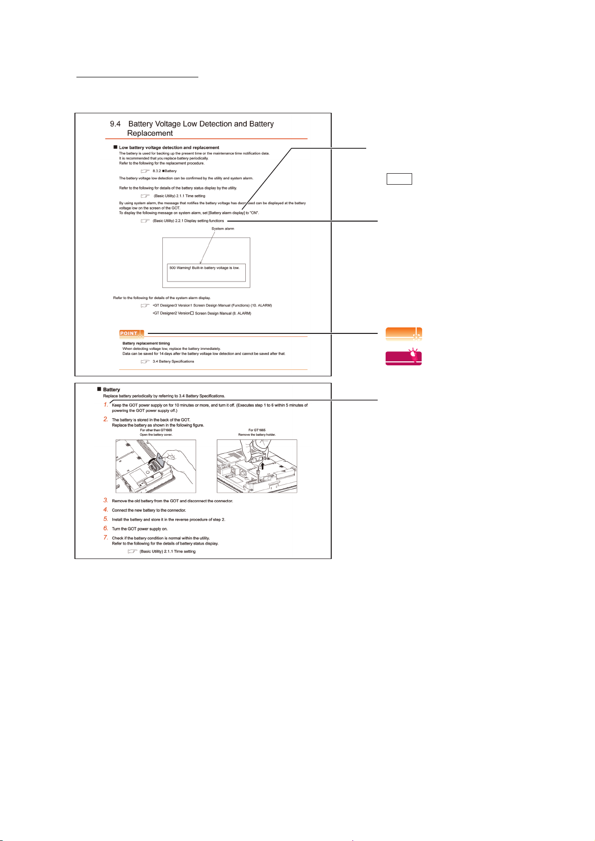
9.4 Battery Voltage Low Detection and Battery Replacement............................................................... 9 - 4
9.5 Backlight Shutoff Detection and Replacement ................................................................................ 9 - 6
9.6 Backlight Replacement .................................................................................................................... 9 - 7
9.6.1 Applicable backlight.............................................................................................................. 9 - 7
9.6.2 Replacement procedure of backlight .................................................................................... 9 - 7
10. TROUBLESHOOTING
10.1 GOT Restoration Sheet ................................................................................................................. 10 - 1
10.2 Troubleshooting in Bus Connection............................................................................................. 10 - 12
10.2.1 Locating error positions .................................................................................................... 10 - 12
10.2.2 Further locating error positions ......................................................................................... 10 - 13
10.2.3 Specific example of troubleshooting................................................................................. 10 - 14
10.3 Error Message and System Alarm............................................................................................... 10 - 15
10.3.1 Error contents display ....................................................................................................... 10 - 15
10.3.2 List of error message/system alarm ................................................................................. 10 - 17
APPENDICES
Appendix1 External Dimensions............................................................................................................ App - 1
Appendix2 Confirming of Versions and Conformed Standards ...........................................................App - 14
Appendix3 Transportation Precautions ...............................................................................................App - 15
Appendix.3.1 Relevant models........................................................................................................App - 15
Appendix.3.2 Transportation guidelines .......................................................................................... App - 15
Appendix4 How to Choose Drive......................................................................................................... App - 16
A - 11

INDEX
REVISIONS
WARRANTY
A - 12

ABOUT MANUALS
The following table lists the manual relevant to GT Designer2 product.
Refer to each manual for any purpose.
Manual Name Packing
GT SoftGOT1000 Version2 Operating Manual Stored in CD-ROM
GT Designer2 Version2 Basic Operation/Data Transfer Manual (For GOT1000 Series) Stored in CD-ROM
GT Designer2 Version2 Screen Design Manual (For GOT1000 Series) 1/3
GT Designer2 Version2 Screen Design Manual (For GOT1000 Series) 2/3
GT Designer2 Version2 Screen Design Manual (For GOT1000 Series) 3/3
GOT1000 Series Connection Manual (1/3)
GOT1000 Series Connection Manual (2/3)
GOT1000 Series Connection Manual (3/3)
GOT1000 Series Extended/Option Functions Manual Stored in CD-ROM
GOT1000 Series Gateway Functions Manual Stored in CD-ROM
GOT1000 Series MES Interface Function Manual Stored in CD-ROM
Stored in CD-ROM
Stored in CD-ROM
Manual Number
(Model code)
SH-080602ENG
(1D7M48)
SH-080529ENG
(1D7M24)
SH-080530ENG
(1D7M25)
SH-080532ENG
(1D7M26)
SH-080544ENG
(1D7M32)
SH-080545ENG
(1D7M33)
SH-080654ENG
(1D7M63)
A - 13

The following table lists the manual relevant to GT Works3 product.
Refer to each manual for any purpose.
Screen creation software manuals
Manual Name
GT Works3 Version1 Installation Procedure Manual
GT Designer3 Version1 Screen Design Manual (Fundamentals) 1/2, 2/2 Stored in CD-ROM
GT Designer3 Version1 Screen Design Manual (Functions) 1/2, 2/2 Stored in CD-ROM
GT Simulator3 Version1 Operating Manual for GT Works3 Stored in CD-ROM
GT Converter2 Version3 Operating Manual for GT Works3 Stored in CD-ROM
Packaging
Enclosed in product
Connection manuals
Manual Name Packaging
GOT1000 Series Connection Manual (Mitsubishi Products) for GT Works3 Stored in CD-ROM
GOT1000 Series Connection Manual (Non-Mitsubishi Products 1) for GT Works3 Stored in CD-ROM
GOT1000 Series Connection Manual (Non-Mitsubishi Products 2) for GT Works3 Stored in CD-ROM
GOT1000 Series Connection Manual (Microcomputer, MODBUS Products, Peripherals) for GT
Works3
Stored in CD-ROM
Manual Number
(Model code)
-
SH-080866ENG
(1D7MB9)
SH-080867ENG
(1D7MC1)
SH-080861ENG
(1D7MB1)
SH-080862ENG
(1D7MB2)
Manual Number
(Model code)
SH-080868ENG
(1D7MC2)
SH-080869ENG
(1D7MC3)
SH-080870ENG
(1D7MC4)
SH-080871ENG
(1D7MC5)
Extended and option function manuals
Manual Name Packaging
GOT1000 Series Gateway Functions Manual for GT Works3 Stored in CD-ROM
GOT1000 Series MES Interface Function Manual for GT Works3 Stored in CD-ROM
GOT1000 Series User's Manual (Extended Functions, Option Functions) for GT Works3 Stored in CD-ROM
GT SoftGOT1000 manuals
Manual Name Packaging
GT SoftGOT1000 Version3 Operating Manual for GT Works3 Stored in CD-ROM
Manual Number
(Model code)
SH-080858ENG
(1D7MA7)
SH-080859ENG
(1D7MA8)
SH-080863ENG
(1D7MB3)
Manual Number
(Model code)
SH-080860ENG
(1D7MA9)
A - 14

GT16 manuals
Manual Name Packaging
GT16 User's Manual (Hardware) Stored in CD-ROM
GT16 User's Manual (Basic Utility) Stored in CD-ROM
GT16 Handy GOT User's Manual Stored in CD-ROM
GT15 manuals
Manual Name Packaging
GT15 User's Manual Stored in CD-ROM
GT14 manuals
Manual Name Packaging
GT14 User's Manual Stored in CD-ROM
Manual Number
(Model code)
SH-080928ENG
(1D7MD3)
SH-080929ENG
(1D7MD4)
JY997D41201
JY997D41202
(09R821)
Manual Number
(Model code)
SH-080528ENG
(1D7M23)
Manual Number
(Model code)
JY997D44801
(09R823)
GT12 manuals
Manual Name Packaging
GT12 User's Manual Stored in CD-ROM
GT11 manuals
Manual Name Packaging
GT11 User's Manual Stored in CD-ROM
GT11 Handy GOT User's Manual Stored in CD-ROM
GT10 manuals
Manual Name Packaging
GT10 User's Manual Stored in CD-ROM
Manual Number
(Model code)
SH-080977ENG
(1D7ME1)
Manual Number
(Model code)
JY997D17501
(09R815)
JY997D20101
JY997D20102
(09R817)
Manual Number
(Model code)
JY997D24701
(09R819)
A - 15

QUICK REFERENCE
Creating a project
Obtaining the specifications and operation methods of GT Designer3
Setting available functions on GT Designer3
Creating a screen displayed on the GOT
Obtaining useful functions to increase efficiency of drawing
Setting details for figures and objects
Setting functions for the data collection or trigger action
Setting functions to use peripheral devices
Simulating a created project on a personal computer GT Simulator3 Version1 Operating Manual for GT Works3
GT Designer3 Version1 Screen Design Manual
(Fundamentals) 1/2, 2/2
GT Designer3 Version1 Screen Design Manual (Functions)
1/2, 2/2
Connecting a controller to the GOT
Obtaining information of Mitsubishi products applicable to the GOT
Connecting Mitsubishi products to the GOT
GOT1000 Series Connection Manual (Mitsubishi Products) for
Connecting multiple controllersto one GOT (Multi-channel function)
Establishing communication between a personal computer and a
controller via the GOT (FA transparent function)
GT Works3
Obtaining information of Non-Mitsubishi products applicable to the GOT • GOT1000 Series Connection Manual (Non-Mitsubishi
Products 1) for GT Works3
Connecting Non-Mitsubishi products to the GOT
Obtaining information of peripheral devices applicable to the GOT
Connecting peripheral devices including a barcode reader to the GOT
• GOT1000 Series Connection Manual (Non-Mitsubishi
Products 2) for GT Works3
GOT1000 Series Connection Manual (Microcomputer,
MODBUS Products, Peripherals) for GT Works3
Transferring data to the GOT
Writing data to the GOT
Reading data from the GOT
Verifying a editing project to a GOT project
GT Designer3 Version1 Screen Design Manual
(Fundamentals) 1/2, 2/2
A - 16

Others
Obtaining specifications (including part names, external dimensions, and
options) of each GOT
Installing the GOT
Operating the utility
Configuring the gateway function GOT1000 Series Gateway Functions Manual for GT Works3
Configuring the MES interface function
Configuring the extended function and option function
• GT16 User's Manual (Hardware)
• GT16 Handy GOT User's Manual
• GT15 User's Manual
• GT14 User's Manual
• GT12 User's Manual
• GT11 User's Manual
• GT11 Handy GOT User's Manual
• GT10 User's Manual
• GT16 User's Manual (Basic Utility)
• GT16 Handy GOT User's Manual
• GT15 User's Manual
• GT14 User's Manual
• GT12 User's Manual
• GT11 User's Manual
• GT11 Handy GOT User's Manual
• GT10 User's Manual
GOT1000 Series MES Interface Function Manual for GT
Works3
GOT1000 Series User's Manual (Extended Functions, Option
Functions) for GT Works3
Using a personal computer as the GOT GT SoftGOT1000 Version3 Operating Manual for GT Works3
A - 17
ABBREVIATIONS AND GENERIC TERMS
Abbreviations and generic terms used in this manual are as follows:
GOT
Abbreviations and generic terms Description
GT1695 GT1695M-X Abbreviation of GT1695M-XTBA, GT1695M-XTBD
GT1685 GT1685M-S Abbreviation of GT1685M-STBA, GT1685M-STBD
GT1675M-S Abbreviation of GT1675M-STBA, GT1675M-STBD
GOT1000 Series
GT1675
GT1672 GT1672-VN Abbreviation of GT1672-VNBA, GT1672-VNBD
GT1665
GT1662 GT1662-VN Abbreviation of GT1662-VNBA, GT1662-VNBD
GT1655 GT1655-V Abbreviation of GT1655-VTBD
GT16
GT1595 GT1595-X Abbreviation of GT1595-XTBA, GT1595-XTBD
GT1585
GT157
GT156
GT155
GT15
GT145
GT14 Abbreviation of GT1455-Q, GT1450-Q
GT1275 GT1275-V Abbreviation of GT1275-VNBA, GT1275-VNBD
GT1265 GT1265-V Abbreviation of GT1265-VNBA, GT1265-VNBD
GT12 Abbreviation of GT1275, GT1265
GT115
GT11 Abbreviation of GT1155-Q, GT1150-Q, GT11 Handy GOT
GT105
GT104
GT1030
GT1020
GT10
GT1675M-V Abbreviation of GT1675M-VTBA, GT1675M-VTBD
GT1675-VN Abbreviation of GT1675-VNBA, GT1675-VNBD
GT1665M-S Abbreviation of GT1665M-STBA, GT1665M-STBD
GT1665M-V Abbreviation of GT1665M-VTBA, GT1665M-VTBD
Abbreviation of GT1695, GT1685, GT1675, GT1672, GT1665, GT1662, GT1655, GT16 Handy
GOT
GT1585V-S Abbreviation of GT1585V-STBA, GT1585V-STBD
GT1585-S Abbreviation of GT1585-STBA, GT1585-STBD
GT1575V-S Abbreviation of GT1575V-STBA, GT1575V-STBD
GT1575-S Abbreviation of GT1575-STBA, GT1575-STBD
GT1575-V Abbreviation of GT1575-VTBA, GT1575-VTBD
GT1575-VN Abbreviation of GT1575-VNBA, GT1575-VNBD
GT1572-VN Abbreviation of GT1572-VNBA, GT1572-VNBD
GT1565-V Abbreviation of GT1565-VTBA, GT1565-VTBD
GT1562-VN Abbreviation of GT1562-VNBA, GT1562-VNBD
GT1555-V Abbreviation of GT1555-VTBD
GT1555-Q Abbreviation of GT1555-QTBD, GT1555-QSBD
GT1550-Q Abbreviation of GT1550-QLBD
Abbreviation of GT1595, GT1585, GT157 , GT156 , GT155
GT1455-Q Abbreviation of GT1455-QTBDE, GT1455-QTBD
GT1450-Q Abbreviation of GT1450-QLBDE, GT1450-QLBD
GT1155-Q
GT1150-Q Abbreviation of GT1150-QLBDQ, GT1150-QLBDA, GT1150-QLBD
GT1055-Q Abbreviation of GT1055-QSBD
GT1050-Q Abbreviation of GT1050-QBBD
GT1045-Q Abbreviation of GT1045-QSBD
GT1040-Q Abbreviation of GT1040-QBBD
Abbreviation of GT1155-QTBDQ, GT1155-QSBDQ, GT1155-QTBDA, GT1155-QSBDA,
GT1155-QTBD, GT1155-QSBD
Abbreviation of GT1030-LBD, GT1030-LBD2, GT1030-LBL, GT1030-LBDW, GT1030-LBDW2,
GT1030-LBLW, GT1030-LWD, GT1030-LWD2, GT1030-LWL, GT1030-LWDW,
GT1030-LWDW2, GT1030-LWLW, GT1030-HBD, GT1030-HBD2, GT1030-HBL,
GT1030-HBDW, GT1030-HBDW2, GT1030-HBLW, GT1030-HWD, GT1030-HWD2,
GT1030-HWL, GT1030-HWDW, GT1030-HWDW2, GT1030-HWLW
Abbreviation of GT1020-LBD, GT1020-LBD2, GT1020-LBL, GT1020-LBDW, GT1020-LBDW2,
GT1020-LBLW, GT1020-LWD, GT1020-LWD2, GT1020-LWL, GT1020-LWDW,
GT1020-LWDW2, GT1020-LWLW
Abbreviation of GT105 , GT104 , GT1030, GT1020
A - 18
Abbreviations and generic terms Description
GT16
GT1665HS-V Abbreviation of GT1665HS-VTBD
Handy
Handy
GOT1000 Series
GOT900 Series Abbreviation of GOT-A900 series, GOT-F900 series
GOT800 Series Abbreviation of GOT-800 series
GOT
GT SoftGOT1000 Abbreviation of GT SoftGOT1000
GOT
GT1155HS-Q Abbreviation of GT1155HS-QSBD
GT11
Handy
GT1150HS-Q Abbreviation of GT1150HS-QLBD
GOT
Communication unit
Abbreviations and generic terms Description
Bus connection unit
Serial communication unit GT15-RS2-9P, GT15-RS4-9S, GT15-RS4-TE
RS-422 conversion unit GT15-RS2T4-9P, GT15-RS2T4-25P
Ethernet communication unit GT15-J71E71-100
MELSECNET/H communication unit GT15-J71LP23-25, GT15-J71BR13
MELSECNET/10 communication unit
CC-Link IE Controller Network communication
unit
CC-Link IE Field Network Communication Unit GT15-J71GF13-T2
CC-Link communication unit
CC-Link interface unit GT11HS-CCL, GT11H-CCL
Interface converter unit GT15-75IF900
Serial multi-drop connection unit GT01-RS4-M
Connection Conversion Adapter GT10-9PT5S
RS-232/485 signal conversion adapter GT14-RS2T4-9P
*1 A9GT-QJ71LP23 + GT15-75IF900 set
*2 A9GT-QJ71BR13 + GT15-75IF900 set
*3 A8GT-J61BT13 + GT15-75IF900 set
GT15-QBUS, GT15-QBUS2, GT15-ABUS, GT15-ABUS2,
GT15-75QBUSL, GT15-75QBUS2L, GT15-75ABUSL, GT15-75ABUS2L
*1
GT15-75J71LP23-Z
GT15-J71GP23-SX
GT15-J61BT13, GT15-75J61BT13-Z
, GT15-75J71BR13-Z
*2
*3
Option unit
Abbreviations and generic terms Description
Printer unit GT15-PRN
Video input unit GT16M-V4, GT15V-75V4
Video/RGB unit
Multimedia unit GT16M-MMR
CF card unit GT15-CFCD
CF card extension unit
External I/O unit GT15-DIO, GT15-DIOR
Sound output unit GT15-SOUT, GT11-50BAT
RGB input unit GT16M-R2, GT15V-75R1
Video/RGB input unit GT16M-V4R1, GT15V-75V4R1
RGB output unit GT16M-ROUT, GT15V-75ROUT
*1
*1 GT15-CFEX + GT15-CFEXIF + GT15-C08CF set.
GT15-CFEX-C08SET
A - 19
Option
Abbreviations and generic terms Description
Memory card
Memory card adaptor GT05-MEM-ADPC
Option function board
Battery GT15-BAT, GT11-50BAT
Protective Sheet
Protective cover for oil
USB environmental protection cover GT16-UCOV, GT16-50UCOV, GT15-UCOV, GT14-50UCOV, GT11-50UCOV
Stand GT15-90STAND, GT15-80STAND, GT15-70STAND, A9GT-50STAND, GT05-50STAND
Attachment
Backlight
Multi-color display board GT15-XHNB, GT15-VHNB
Connector conversion box GT11H-CNB-37S, GT16H-CNB-42S
Emergency stop sw guard cover GT11H-50ESCOV, GT16H-60ESCOV
Memory loader GT10-LDR
Memory board GT10-50FMB
Panel-mounted USB port extension GT14-C10EXUSB-4S, GT10-C10EXUSB-5S
CF card
SD card L1MEM-2GBSD, L1MEM-4GBSD
GT05-MEM-16MC, GT05-MEM-32MC, GT05-MEM-64MC, GT05-MEM-128MC,
GT05-MEM-256MC, GT05-MEM-512MC, GT05-MEM-1GC, GT05-MEM-2GC,
GT05-MEM-4GC, GT05-MEM-8GC, GT05-MEM-16GC
GT16-MESB, GT15-FNB, GT15-QFNB, GT15-QFNB16M,
GT15-QFNB32M, GT15-QFNB48M, GT15-MESB48M, GT11-50FNB
GT16-90PSCB, GT16-90PSGB, GT16-90PSCW, GT16-90PSGW,
GT16-80PSCB, GT16-80PSGB, GT16-80PSCW, GT16-80PSGW,
For GT16
For GT15
For GT14 GT14-50PSCB, GT14-50PSGB, GT14-50PSCW, GT14-50PSGW
For GT12 GT11-70PSCB, GT11-65PSCB
Fo r GT11 GT 11 -50 P S CB, G T 11-5 0 P SG B , GT11 - 5 0PS C W, G T11- 5 0 PSG W, G T 11H- 5 0 PS C
For GT10
GT05-90PCO, GT05-80PCO, GT05-70PCO, GT05-60PCO, GT05-50PCO,
GT16-50PCO, GT10-40PCO, GT10-30PCO, GT10-20PCO
GT15-70ATT-98, GT15-70ATT-87, GT15-60ATT-97, GT15-60ATT-96,
GT15-60ATT-87, GT15-60ATT-77, GT15-50ATT-95W, GT15-50ATT-85
GT16-90XLTT, GT16-80SLTT, GT16-70SLTT, GT16-70VLTT, GT16-70VLTTA, GT16-70VLTN,
GT16-60SLTT, GT16-60VLTT, GT16-60VLTN, GT15-90XLTT, GT15-80SLTT, GT15-70SLTT,
GT15-70VLTT, GT15-70VLTN, GT15-60VLTT, GT15-60VLTN
GT16-70PSCB, GT16-70PSGB, GT16-70PSCW, GT16-70PSGW,
GT16-60PSCB, GT16-60PSGB, GT16-60PSCW, GT16-60PSGW,
GT16-50PSCB, GT16-50PSGB, GT16-50PSCW, GT16-50PSGW,
GT16-90PSCB-012, GT16-80PSCB-012, GT16-70PSCB-012,
GT16-60PSCB-012, GT16-50PSCB-012, GT16H-60PSC
GT15-90PSCB, GT15-90PSGB, GT15-90PSCW, GT15-90PSGW,
GT15-80PSCB, GT15-80PSGB, GT15-80PSCW, GT15-80PSGW,
GT15-70PSCB, GT15-70PSGB, GT15-70PSCW, GT15-70PSGW,
GT15-60PSCB, GT15-60PSGB, GT15-60PSCW, GT15-60PSGW,
GT15-50PSCB, GT15-50PSGB, GT15-50PSCW, GT15-50PSGW
GT10-50PSCB, GT10-50PSGB, GT10-50PSCW, GT10-50PSGW,
GT10-40PSCB, GT10-40PSGB, GT10-40PSCW, GT10-40PSGW,
GT10-30PSCB, GT10-30PSGB, GT10-30PSCW, GT10-30PSGW,
GT10-20PSCB, GT10-20PSGB, GT10-20PSCW, GT10-20PSGW
A - 20
Software
Abbreviations and generic terms Description
GT Works3
GT Designer3 Abbreviation of screen drawing software GT Designer3 for GOT1000 series
GT Simulator3 Abbreviation of screen simulator GT Simulator3 for GOT1000/GOT900 series
GT SoftGOT1000 Abbreviation of monitoring software GT SoftGOT1000
GT Converter2 Abbreviation of data conversion software GT Converter2 for GOT1000/GOT900 series
GT Designer2 Classic Abbreviation of screen drawing software GT Designer2 Classic for GOT900 series
GT Designer2 Abbreviation of screen drawing software GT Designer2 for GOT1000/GOT900 series
iQ Works Abbreviation of iQ Platform compatible engineering environment MELSOFT iQ Works
MELSOFT Navigator
GX Works2
GX Simulator2 Abbreviation of GX Works2 with the simulation function
GX Simulator
GX Developer
GX LogViewer
PX Developer
MT Works2
MT Developer
MR Configurator2
MR Configurator
FR Configurator
NC Configurator Abbreviation of CNC parameter setting support tool NC Configurator
FX Configurator-FP
FX3U-ENET-L Configuration tool Abbreviation of FX3U-ENET-L type Ethernet module setting software (SW1D5-FXENETL-E)
RT ToolBox2 Abbreviation of robot program creation software (3D-11C-WINE)
MX Component
MX Sheet
LCPU Logging Configuration Tool Abbreviation of LCPU Logging Configuration Tool (SW1DNN-LLUTL-E)
Abbreviation of the SW DNC-GTWK3-E and SW DNC-GTWK3-EA
Generic term for integrated development environment software included in the SW DNC-IQWK (iQ
Platform compatible engineering environment MELSOFT iQ Works)
Abbreviation of SW DNC-GXW2-E and SW DNC-GXW2-EA type programmable controller
engineering software
Abbreviation of SW D5C-LLT-E(-EV) type ladder logic test tool function software packages
(SW5D5C-LLT (-EV) or later versions)
Abbreviation of SW D5C-GPPW-E(-EV)/SW D5F-GPPW-E type software package
Abbreviation of SW DNN-VIEWER-E type software package
Abbreviation of SW D5C-FBDQ-E type FBD software package for process control
Abbreviation of motion controller engineering environment MELSOFT MT Works2
(SW DNC-MTW2-E)
Abbreviation of SW RNC-GSV type integrated start-up support software for motion controller Q series
Abbreviation of SW DNC-MRC2-E type Servo Configuration Software
Abbreviation of MRZJW -SETUP E type Servo Configuration Software
Abbreviation of Inverter Setup Software (FR-SW -SETUP-WE)
Abbreviation of parameter setting, monitoring, and testing software packages for FX3U-20SSC-H
(SW D5C-FXSSC-E)
Abbreviation of MX Component Version (SW D5C-ACT-E,SW D5C-ACT-EA)
Abbreviation of MX Sheet Version (SW D5C-SHEET-E,SW D5C-SHEET-EA)
License key (for GT SoftGOT1000)
Abbreviations and generic terms Description
License GT15-SGTKEY-U, GT15-SGTKEY-P
License key (for GT SoftGOT2)
Abbreviations and generic terms Description
License key A9GTSOFT-LKEY-P (For DOS/V PC)
License key FD SW5D5F-SGLKEY-J (For PC CPU module)
A - 21

Others
Abbreviations and generic terms Description
IAI Abbreviation of IAI Corporation
AZBIL Abbreviation of Azbil Corporation (former Yamatake Corporation)
OMRON Abbreviation of OMRON Corporation
KEYENCE Abbreviation of KEYENCE CORPORATION
KOYO EI Abbreviation of KOYO ELECTRONICS INDUSTRIES CO., LTD.
SHARP Abbreviation of Sharp Manufacturing Systems Corporation
JTEKT Abbreviation of JTEKT Corporation
SHINKO Abbreviation of Shinko Technos Co., Ltd.
CHINO Abbreviation of CHINO CORPORATION
TOSHIBA Abbreviation of TOSHIBA CORPORATION
TOSHIBA MACHINE Abbreviation of TOSHIBA MACHINE CO., LTD.
HITACHI IES Abbreviation of Hitachi Industrial Equipment Systems Co., Ltd.
HITACHI Abbreviation of Hitachi, Ltd.
FUJI Abbreviation of FUJI ELECTRIC CO., LTD.
PANASONIC Abbreviation of Panasonic Corporation
PANASONIC INDUSTRIAL DEVICES SUNX Abbreviation of Panasonic Industrial Devices SUNX Co., Ltd.
YASKAWA Abbreviation of YASKAWA Electric Corporation
YOKOGAWA Abbreviation of Yokogawa Electric Corporation
ALLEN-BRADLEY Abbreviation of Allen-Bradley products manufactured by Rockwell Automation, Inc.
GE Abbreviation of GE Intelligent Platforms
LS IS Abbreviation of LS Industrial Systems Co., Ltd.
SCHNEIDER Abbreviation of Schneider Electric SA
SICK Abbreviation of SICK AG
SIEMENS Abbreviation of Siemens AG
RKC Abbreviation of RKC INSTRUMENT INC.
HIRATA Abbreviation of Hirata Corporation
MURATEC Abbreviation of Muratec products manufactured by Muratec Automation Co., Ltd.
PLC Abbreviation of programmable controller
Temperature controller Generic term for temperature controller manufactured by each corporation
Indicating controller Generic term for indicating controller manufactured by each corporation
Control equipment Generic term for control equipment manufactured by each corporation
CHINO controller Abbreviation of indicating controller manufactured by CHINO CORPORATION
PC CPU module Abbreviation of PC CPU Unit manufactured by CONTEC CO., LTD
GOT (server) Abbreviation of GOTs that use the server function
GOT (client) Abbreviation of GOTs that use the client function
Windows
Intelligent function module
MODBUS
MODBUS
font
/RTU
/TCP Generic term for the protocol designed to use MODBUS protocol messages on a TCP/IP network
Abbreviation of TrueType font and OpenType font available for Windows
(Differs from the True Type fonts settable with GT Designer3)
Indicates the modules other than the PLC CPU, power supply module and I/O module that are
mounted to the base unit
Generic term for the protocol designed to use MODBUS
communication
protocol messages on a serial
A - 22
HOW TO USE THIS MANUAL
POINTPOINTPOINT
HINTHINTHINT
Refers to information
required for operation.
Refers to information useful
for operation.
Shows the operation steps.
Operate the steps from the step 1.
: Shows the setting item displayed on
the software screen or the GOT
screen.
[]
: Refers to a button displayed on
the computer screen or the
GOT screen, or a key of the
computer keyboard.
Show the items including detailed explanation
(Hardware) :
GT16 User’s Manual (Hardware)
(Basic Utility) :
GT16 User’s Manual (Basic Utility)
Following symbols are used in this manual
* The above is different from the actual page, as it is provided for explanation only.
A - 23
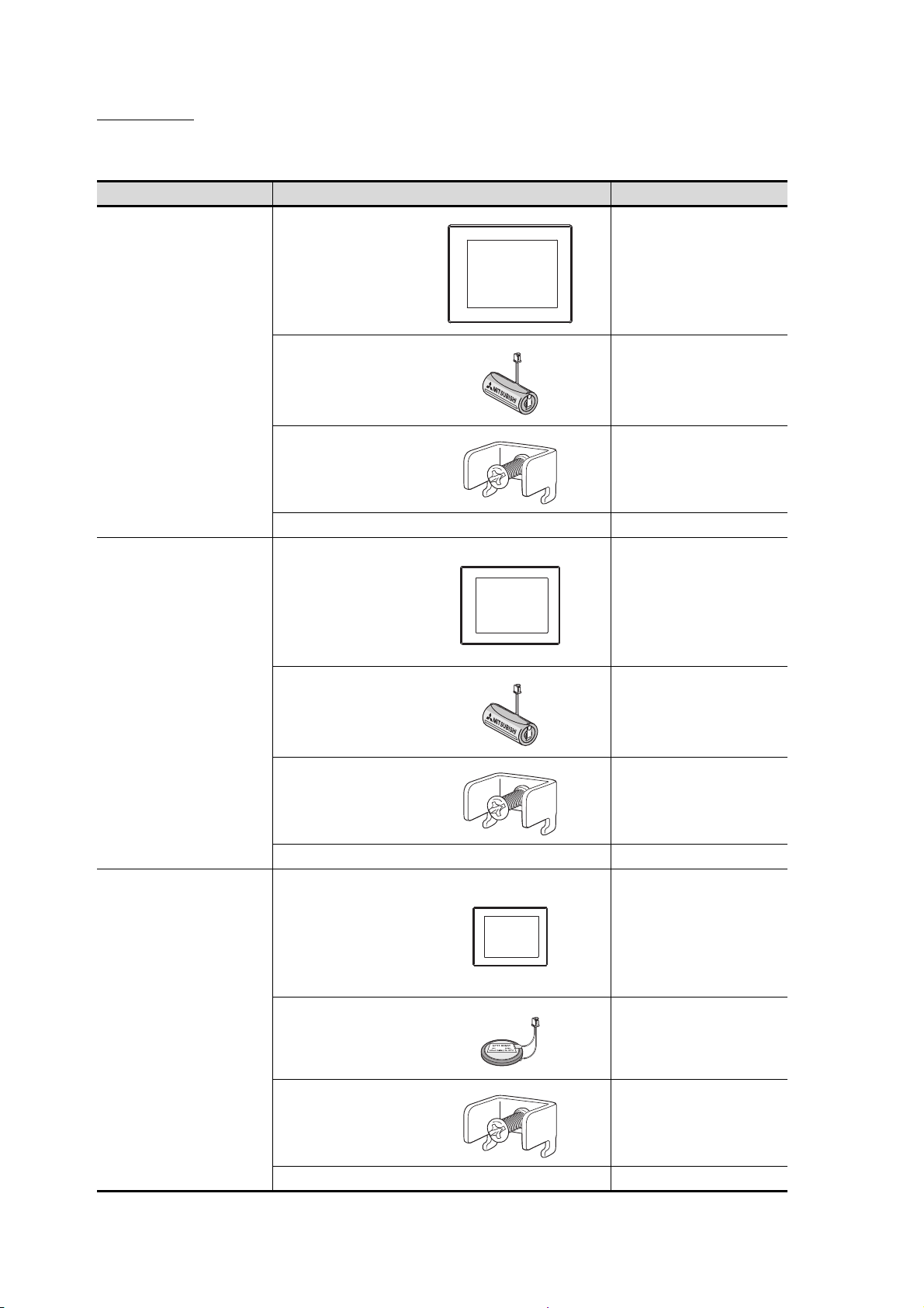
PACKING LIST
After unpacking, confirm that the following parts are included.
Model Product Quantity
GOT 1
GT1695M-X
GT1685M-S
GT1675M-S
GT1675M-V
GT1675-VN
GT1672-VN
GT1665M-S
GT1665M-V
GT1662-VN
Battery 1
Installation fitting 8
GT16 General Description 1
GOT 1
Battery 1
Installation fitting 4
A - 24
GT1655-V
GT16 General Description 1
GOT 1
Battery 1
Installation fitting 4
GT16 General Description 1
1. OVERVIEW
PLC
Connector for
program
GOT
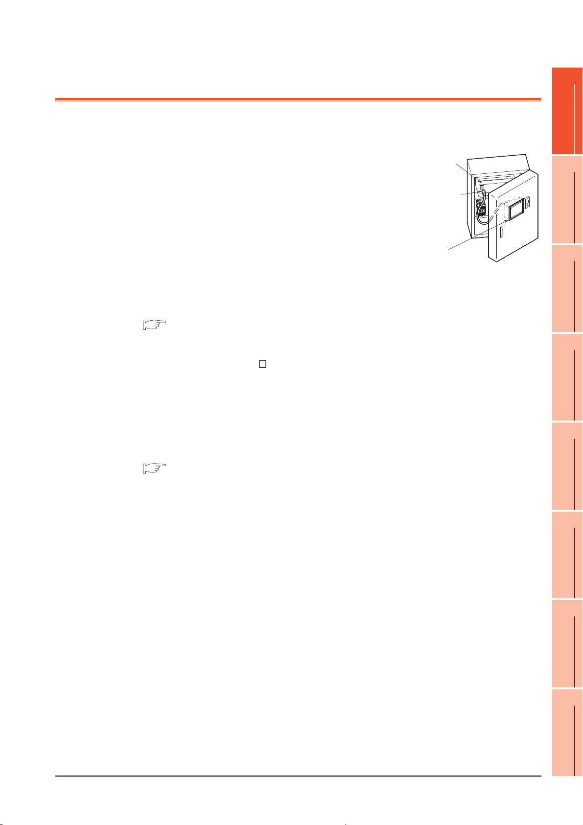
About GOT
GOT is installed on the panel surface of control panel or operating panel and
connects to the PLC in the control panel. GOT carries out switch operation, lamp
display, data display, and message display etc.
For display screen, two kinds of display screens, user-created screen and utility
screen are available.
(1) User-created Screen
User screen is a screen drawn by GT Designer3 or GT Designer2.
The objects of "Touch switch", "Lamp display", "Comment display", and
"Numeric display" can be laid out arbitrarily to be displayed.
Moreover, the multiple screens created by GT Designer3 or GT Designer2
can be overlapped and switched to be displayed.
For details, refer to the following.
1
2
SYSTEM
3
OVERVIEW
CONFIGURATION
•GT Designer3 Version1 Screen Design Manual (Fundamentals)
•GT Designer3 Version1 Screen Design Manual (Functions)
•GT Designer2 Version Basic Operation/Data Transfer Manual
•GT Designer2 Version Screen Design Manual
(2) Utility Screen
Utility screen is a screen prepared beforehand for GOT.
Installing BootOS and standard OS in the GOT from GT Designer3 or GT Designer2 enables utility screen
displaying.
The utility screen has menus as [Brightness/contrast adjustment screen] and [GOT memory check screen] etc.
For details, refer to the following.
(Basic Utility) 1 to 6
EMC AND LOW
SPECIFICATIONS
4
PART NAME AND
SETTINGS
5
VOLTAGE
6
INSTALLATION
7
DIRECTIVE
WIRING
8
OPTION
1 - 1

1.1 Features
(1) Improved monitoring performance and connectivity to FA devices
• GT1695M-X, GT1685M-S, GT1675M-S, GT1675M-V, GT1665M-S, GT1665M-V, GT1655-V: The TFT color
liquid crystal display (high intensity, wide angle view, and high definition type) provides clear full-color display
and displays small characters clearly.
(Displays digital images of BMP and other formats in 65536 colors.)
GT1675-VN, GT1672-VN, GT1662-VN: The TFT color liquid crystal display provides 4096 or 16 colors to
offer a wide range of models that meet user requirements.
• Provides multi-language display function based on Unicode2.1 True Type font and high-speed drawing of
beautiful text.
• High speed monitoring through high speed communication at maximum of 115.2kbps.
• High speed display and high speed touch switch response.
• The operation performance is improved by the analog touch panel.
• GT1695M-X, GT1685M-S, GT1675M-S, GT1675M-V, GT1665M-S, GT1665M-V: Applicable to a video/RGB
unit and a multimedia unit.
(2) More efficient GOT operations including screen design, startup, adjustment, management and
maintenance works
• GT1695M-X, GT1685M-S, GT1675M-S, GT1675M-V, GT1665M-S, GT1665M-V, GT1655-V: 15MB user
memory is included as standard.
GT1675-VN, GT1672-VN, GT1662-VN: 11MB user memory is included as standard.
• The RS-232 interface is included as standard.
• The RS-422/485 interface is included as standard.
• The CF card interface is included as standard.
• The Ethernet interface is included as standard.
• Font installation is available to increase the system fonts.
• Combined use of 4 types of alarms (system alarm, user alarm, alarm history, alarm popup display) realizes
more efficient alarm notification.
• Maintenance timing report function is available that measures the backlight energization time and notifies of
maintenance time.
• The USB interface is positioned on the GOT front. This enables the system startup to be performed more
efficiently using FA device startup tool, and eliminates the necessity of indirect works (opening and closing the
control panel, cable replacement, cable rewiring) in order to improve the working efficiency.
• The blown backlight bulb can be confirmed even during screen saving, with the blinked POWER LED at
backlight shutoff detection.
1 - 2
(3) Enhanced support of FA device setup tools
• Transferring and monitoring sequence programs with the personal computer connected to the GOT can be
executed when connecting to a PLC CPU with the direct CPU connection or bus connection. (FA transparent
function)
1.1 Features
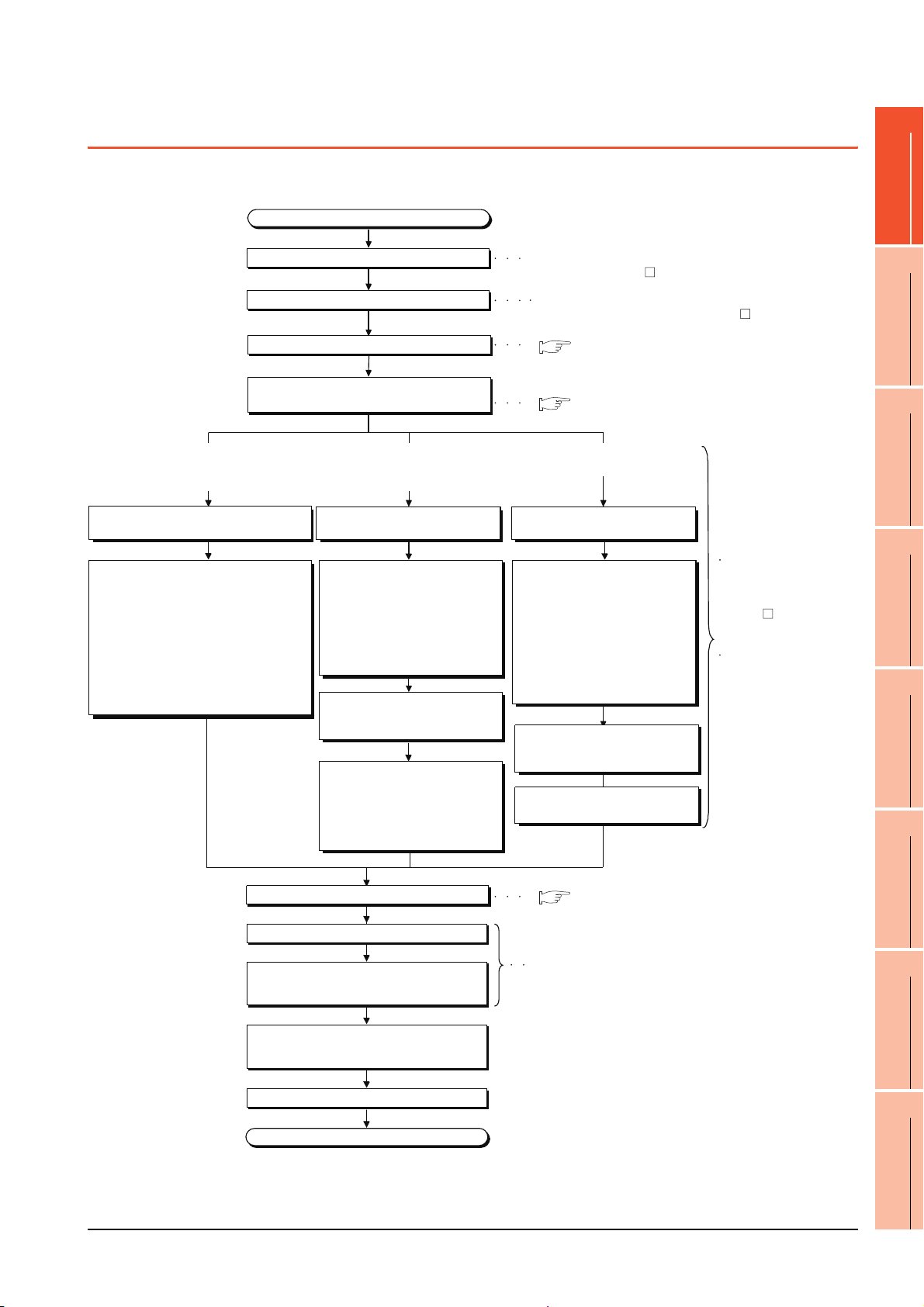
1.2 Rough Pre-operation Procedure
Start
Create project data.
Check the Communication settings.
End
Refer to GOT1000 Series Connection Manual for GT Works3
and a controller used or GOT1000 Series Connection Manual
for GT Designer2/GT Works2
Insert the CF card in the PC.
Insert the CF card in the PC.
Install GT Works3 or GT Designer2 in the PC.
Wire for the GOT power supply.
Mount the option function board.
(As necessary)
Refer to GT Works3 Version1 Installation Instructions or
GT Designer2 Version Basic Operation/Data Transfer Manual
Refer to GT Designer3 Version1 Screen Design Manual
(Fundamentals) or GT Designer2 Version
Screen Design Manual
When transferring data from PC to
built-in flash memory and starting
GOT with built-in flash memory.
When transferring data from CF card
to built-in flash memory and starting
GOT with built-in flash memory.
When transferring data to CF card
and starting GOT with CF card.
Connect GOT and PC with a USB
cable or RS-232 cable.
Transfer the OS and project data to
be installed on the GOT from the PC
to the GOT.
1) Install standard monitor OS,
communication driver, extended
function OS, option OS to the
GOT.
After installation is completed, the
GOT automatically restarts.
2) Download the project data created
by the PC. *1
Write the OS and project data to be
installed on the GOT from the PC to
the CF card.
1) Write the standard monitor OS,
communication driver, extended
function OS, option OS, project
data in the CF card.
Write the OS and project data to be
installed on the GOT from the PC to
the CF card.
1) Set the OS boot drive to
[A: Standard CF Card]. *2
2) Write the standard monitor
OS, communication driver,
option OS, extended
function OS, project data,
and special data into the CF card.
Refer to GT Designer3
Version1 Screen Design
Manual (Fundamentals)
or GT Designer2
Version Basic Operation/
Data Transfer Manual
Refer to GT16 User's
Manual (Basic Utility)
Chapter 7 INSTALLATION
OF COREOS, BOOTOS
AND STANDARD OS in
this manual for the
operations of GOT.
Check that the CF card access
switch is off, and insert the CF card
into the GOT.
Turn on the CF card access switch,
and then install or download the
standard monitor OS,
communication driver, option OS,
extended function OS, and project
data.
Check that the CF card access
switch is off, and insert the CF card
into the GOT.
Mount units to GOT.
Connect the GOT and controller
with a cable.
Turn on the power supply of GOT and
the system of the connection destination.
Start the monitor.
Turn on the CF card access switch.
( 7. WIRING)
( 8. OPTION)
( 8. OPTION)
The outline procedure before operating GOT is shown.
1
2
SYSTEM
3
OVERVIEW
CONFIGURATION
EMC AND LOW
SPECIFICATIONS
4
PART NAME AND
SETTINGS
5
VOLTAGE
6
INSTALLATION
7
DIRECTIVE
1.2 Rough Pre-operation Procedure
WIRING
8
OPTION
1 - 3
* 1 By connecting with the Ethernet interface included as standard in GT 16, project data can be downloaded/uploaded.
POINTPOINTPOINT
For download/upload of project data with the Ethernet connection, BootOS and standard monitor OS should be installed in the
GOT in advance so that the GOT and PC can communicate with each other via Ethernet by setting Communication Settings.
Refer to the following manual for details.
•GT Designer3 Version1 Screen Design Manual (Fundamentals)
(Chapter 8 COMMUNICATION WITH GOT)
* 2 The B drive or E drive cannot be set as the OS boot drive.
•GT Designer2 Version Basic Operation/Data Transfer Manual (Chapter 8 TRANSFERRING DATA)
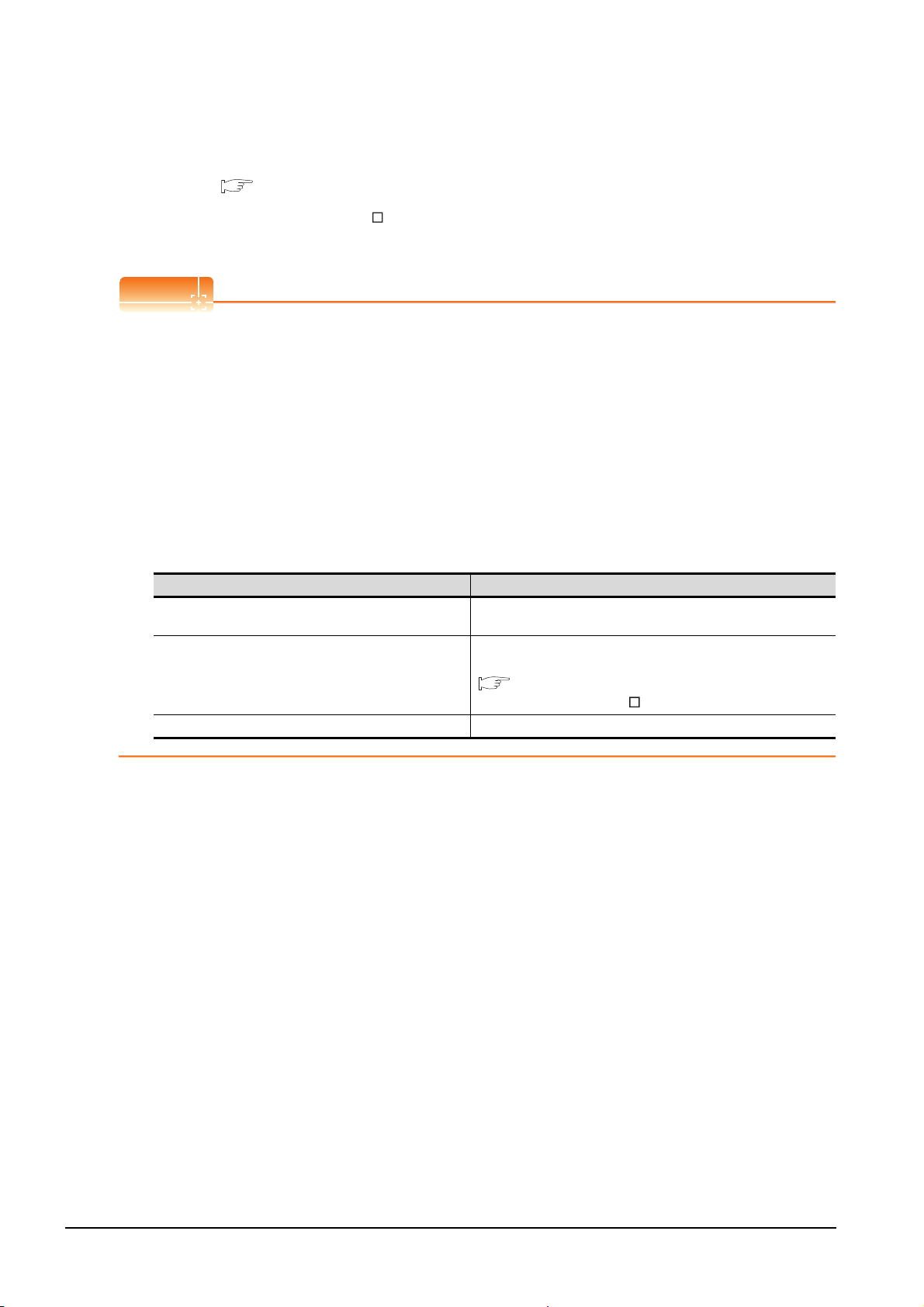
Precautions for setting OS boot drive to [A: Standard CF Card]
(1) GOT startup time
When the OS boot drive is set to [A: Standard CF Card], the GOT startup time with the A drive takes longer
than that with the C drive.
The GOT startup time with the A drive differs depending on the CF card type, the numbers of extended
function OSs and option OSs, and project data size.
(2) Handling CF card during booting OS
Do not remove the CF card and do not turn off the CF card access switch during booting the OS.
Doing so causes the boot to fail. As a result, the GOT does not start correctly.
(3) Corrective actions when OS cannot be booted
The OS cannot be booted in the following conditions.
Take the following corrective actions, and then boot the OS again.
Condition Corrective action
The type of the GOT to be used differs from the GOT type data
set with GT Designer3 or GT Designer2 stored in the CF card.
The GOT has insufficient memory.
The CF card access switch is off. Turn on the CF card access switch.
Prepare the CF card where the OSs and project data of the same GOT
type as the GOT to be used are written.
Delete unnecessary data stored in the memory of GOT.
For details, refer to the following manual.
•GT Designer3 Version1 Screen Design
•GT Designer2 Version Basic Operation/Data Transfer Manual
Manual (Fundamentals)
1 - 4
1.2 Rough Pre-operation Procedure
 Loading...