

Mitsubishi Electric GK-3506SA, GK-3509SA, GK-3512SA Operating And Installation Instructions
Be sure to read this instruction manual before starting installation work.
Installation work must be carried out by a dealer or a specialist installation contractor.
This is a single-phase product. Check the power supply before proceeding with the installation work.
Please be absolutely sure to read through the following information: it will help you to install the Air Curtain correctly
and safely and to operate it properly.
The precautions presented here contain important safety information: be sure to follow the applicable instructions given.
AIR CURTAIN
Models:
GK-3506SA
GK-3509SA
GK-3512SA
OPERATING AND INSTALLATION INSTRUCTIONS
0104872HB9204
Prohibited
Do NOT disassemble.
Do not use where water is
present.
Do NOT touch.
You must follow the
instructions given.
Grounding is required.
Beware of rotating objects.
WARNINGS
This applies to mishandling or
misoperation of the product which
may lead to a fatal or serious injury.
¡
Do not touch the moving parts.
(You may injure yourself.)
¡ Do not attempt remodelling under any circumstances. Disassembly and repair are permitted only be qualified repair
engineers.
(The product may cause fire, electrical shock and/or injury)
¡ Do not apply water to the product or splash water onto it.
(Short-circuiting or electrical shock may be caused.)
¡ Do not use the product where the combustion area of its combustion device will be directly exposed to wind or air
movement.
(This may cause incomplete combustion or result in the flames being extinguished, leading to carbon monoxide poisoning.)
¡ When passing the product and metal ducts connected to the product through wooden buildings lined or covered with
metal or wire laths or with metal sheets, install the product and ducts in such a way that they will not make electrical
contact with the metal or wire laths or metal sheets. (Ignition may occur if there are power leaks.)
¡ Before proceeding with maintenance work, be absolutely sure to set the circuit-breaker on the power board to the OFF
position. In addition, do not perform the work with wet hands. (Electrical shock or injury may result.)
¡ Ground the product properly.
(Electrical shock may be caused in case of malfunctioning or power leaks.)
¡ Do not poke your fingers or any objects into the air outlet ports or moving parts during operation since this is dangerous.
(You may injure yourself.)
¡ If operation stops while the power is still switched on, do not touch the product under any circumstances.
(There is a danger that the unit could suddenly start operating again and cause injury. There is also a danger of electrical shock.)
Be sure to hand over these Operating and Installation Instructions to the user when the
installation work has been completed.
Essential Safety Precautions
¡
The graphic symbols have the following significance.
–1–
Trial Operation
When the installation work is complete, it is advised to re-check both the wiring and the fixing of the unit so that this product operates
correctly with no vibration or noise.
Operation
Maintenance
The Air Curtain should be cleaned when it gets dirty – roughly once every three months as a general rule. Also, be sure to clean and test run
the Air Curtain before starting operation for the summer and winter seasons.
¡ Always switch power off before cleaning the unit.
If there is dirt on the front panel, remove it with a vacuum cleaner. Also, if the inside of this product is extremely dirty, clean it off with a
feather duster, etc.
<
NOTE
>
¡ Do not use solvents such as the following to clean the unit:
Paint thinner, alcohol, benzine, gasoline, kerosene, aerosol sprays, alkaline solvents, or chemicals in chemically treated cleaning
cloths. (Surface deterioration or discoloration could result.)
High
LowONOFF
–
20° + 20°
Unit body
Air Outlet
Power SwitchAirvolume Switch
1.Turn the power switch ON. (Press
the I side.)
2.Set the air volume switch on High or
Low, whichever you prefer.
3.Move the outlet louver and adjust
the air direction.
(When adjusting the louver, do not
use a tool or other implement.)
The outlet louver can be adjusted by
approximately 20º on the inside and
the outside units.
4.To stop the air curtain, turn the power
switch OFF. (Press the O side.)
¡
When cooling the inside.
1. If there is outside wind, blow air so that it is
directed straight downward.
2. If there is no outside wind, and if there is an opening
on the inside, blow air slightly toward the inside.
3. If there is no outside wind, and the inside is closed,
blow air slightly toward the outside.
¡
When heating the inside.
1. If there is outside wind, blow air slightly toward
the outside.
2. If there is no outside wind, blow air either straight
downward or slightly toward the inside.
¡ If the temperature difference is great between
the inside and outside of the refrigerator, etc.
1. Blow air slightly toward the outside.
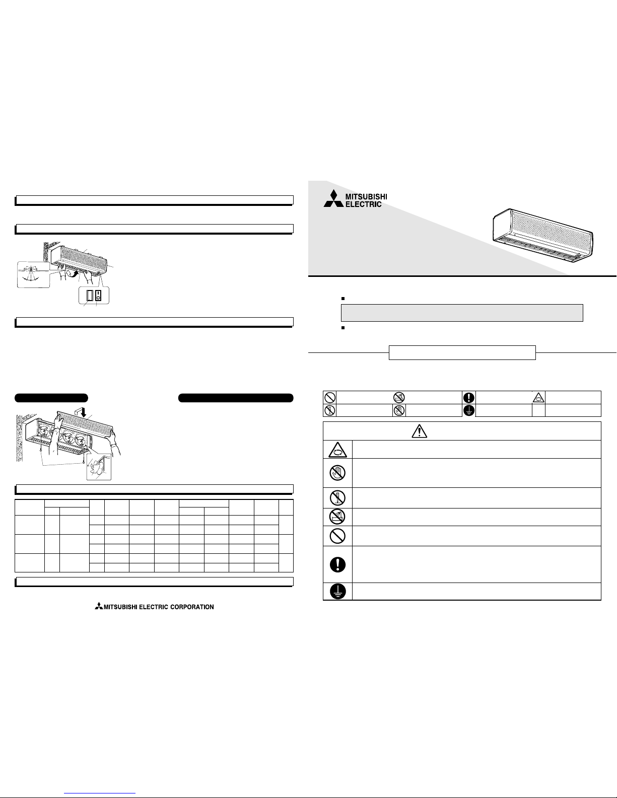
Nut
Blades
Front Panel
Panel Installation Screws
After reading this information, keep it in a place where any person using the product can refer
to it at any time.
Removing each Part
1.
Take out the two
screws used to install
the front panel.
2.Pull the front part of
the front panel, then
lift it up and off the
hooks on the unit’s
body and remove it.
Take off the nuts, then
pull the blades off the
fan motor shafts.
After-Sales Service
Please contact the dealer from whom the unit was purchased concerning after-sales service.
Specifications
TYPE
GK-3506SA
GK-3509SA
GK-3512SA
Power Source
Frequency
Voltage
50Hz
single phase
220-240V
single phase
220-240V
single phase
220-240V
50Hz
50Hz
Speed
control
High 165-175 0.75-0.75 16-17.5
165-180 0.75-0.75 12.0-14.0
250-265 1.1-1.1 16.0-17.5
250-270 1.1-1.1 12.0-14.0
335-355 1.5-1.5 16-17.5
335-360 1.5-1.5 12.0-14.0
1440-1560
1190-1350
2160-2340
1790-2030
2880-3120
2380-2700
400-433
331-376
600-650
497-564
800-867
663-752
64.5-66.5
61.0-64.0
66.0-68.5
63.0-66.0
67.5-70.0
64.5-67.5
1.4
13
20
25
1.3
2.1
1.9
2.8
2.6
Low
High
Low
High
Low
Input
(W)
Maximum
load current(A)
Air velocity
Max(m/s)
Air volume
(m
3
/h) (L/s)
Noise
(dB)
Starting
current (A)
Weight
(kg)
Reassembly and Inspection after Cleaning
When cleaning is finished, reverse the disassembly
steps to reassemble the unit.
Inspect the following items as you reassemble the unit.
1. The fan fits onto the shaft in a specific orientation. Be
sure not to install it upside-down.
2. There are no scratches on the wiring inside the
unit body!
3. The unit body, fans, nuts, and front panel all have
been mounted securely.
4. Switch power on and confirm that the Air Curtain
operates correctly.
CAUTIONS
This applies to mishandling or misoperation of
the product which will lead to injury or damage
to your home, household effects, etc.
¡
Do not hang on the product or swing from it.
(It may fall, resulting in injury.)
¡ Use Single-phase 220~240 V, 50 Hz power supply. (If the wrong power supply is used, it could cause a fire or electric shock.)
¡ When installing the main unit, select a location which is sufficiently strong, and install the unit securely.
(Failure to do so may result in the unit falling, resulting in injury.)
¡ Install the parts properly and securely. (Failure to do so may result in the parts falling, resulting in injury.)
¡ Wiring work should be performed safely and reliably.
(Poor connections or errors in the wiring work could result in electrical shock or fire.)
¡ During installation and maintenance, always wear gloves. (If gloves are not worn, your hands could be injured.)
¡ If the product is not going to be used for a prolonged period of time, be absolutely sure to set the circuit-breaker on the
power board to the OFF position. (Deterioration in the insulation may cause electrical shock, power leaks or fire.)
¡ Never use the product in a bathroom or other location with excessive moisture (more than 90% RH).
(Electrical shock or fire may be caused.)
Notes
¡ The digits in the model number indicate the standard barrier distance and installation width. (In the case of the GK-3509SA, the standard barrier
distance is 3.5 m and the installation width is 90 cm.) The Air Curtain will not be effective if the air flow is too weak or if it is too strong.
Make sure to confirm the installation height and the model.
¡ When installing the Air Curtain at the entrance to a store or office, the air outflow opening should be oriented toward the inside. However, it
may be oriented toward the outside provided that the unit is installed under eaves or an awning that prevents rain from falling on it and there is
no danger of rain being sucked into the intake opening. Also, the unit must be installed outside if it is to be mounted on a freezer room.
¡ Should a power failure occur, be sure to turn the unit’s power switch off. (Otherwise, there is a danger that a malfunction could occur if the
unit’s fan suddenly starts to turn when power is restored.)
¡ Use a motor circuit breaker or the like with the wiring system.
¡ The appliance is not intended for use by young children or infirm persons without supervision.
¡ Young children should be supervised to ensure that they do not play with the appliance.
Description of Functions
¡ The unit is equipped with a overheating prevention device (thermal fuse) to prevent overheating of the motors and resistors. During abnormal
conditions, such as if the ambient temperature is unusually high, if an overload occurs, if a phase interruption occurs during operation, or if
operation is restricted in some way, the fuse will burn out, preventing power from being supplied to the unit. Should this occur, the unit cannot
be restarted. Should the power be cut off while the unit is operating, perform the steps below before restarting the unit.
Treatment:
It is necessary to switch off the power supply, remedy the cause of the problem, and replace the motors and capacitors.
Also, if the portion of the unit where the motors are mounted has become malformed or is otherwise abnormal, the mounting should be
replaced as well. Contact a specialist installation contractor to perform the replacement.
External Dimensional Diagram
Vinyl cabtyre cable
3 conductors x 0.75 E, effective length: 1 m
D-12 x 21 Slotted hole
Air Volume Switch
Power Switch
This product can be installed vertically.
Air flow
direction
Air flow direction
A
14.5
292
14.5
150
300
18.5
8520
50
18
E
Direction of
rotation
C
238
B
Table of dimension changes
Unit (mm)
Accessories
Parts GK-3506SA
GK-3509SA
GK-3512SA
Wall mounting plate 1
4
4
4
1
8
8
8
Washers
Spring washers
Nuts (M10)
TYPE
GK-3506SA
GK-3509SA
GK-3512SA
A
600
900
1180
287.5
76
355.5
..
588
867.5
4
8
8
2
3
4
B C D E (Number of fans)
Mounting Method
Mounting locations and surfaces differ, but in any case make sure that the unit is mounted sufficiently securely and that it is level.
<
NOTE
>
¡ In the case of a standard installation (with the unit mounted horizontally), install it so that the air outlet is facing downward.
¡ If there is a wall on the side of the air curtain, install the wall mounting plate 40 mm or more from the wall. Otherwise, the air curtain’s
body will hit the side wall and you will not be able to install it.
¡ If multiple units are being installed continuously, install the mounting plates at an interval of 80~95 mm from each other.
¡ If you are mounting the air curtain on a wall, leave a gap of 55 mm or more from the ceiling to the mounting plate. If it is closer than
that, the unit will hit against the ceiling and you will not be able to install it.
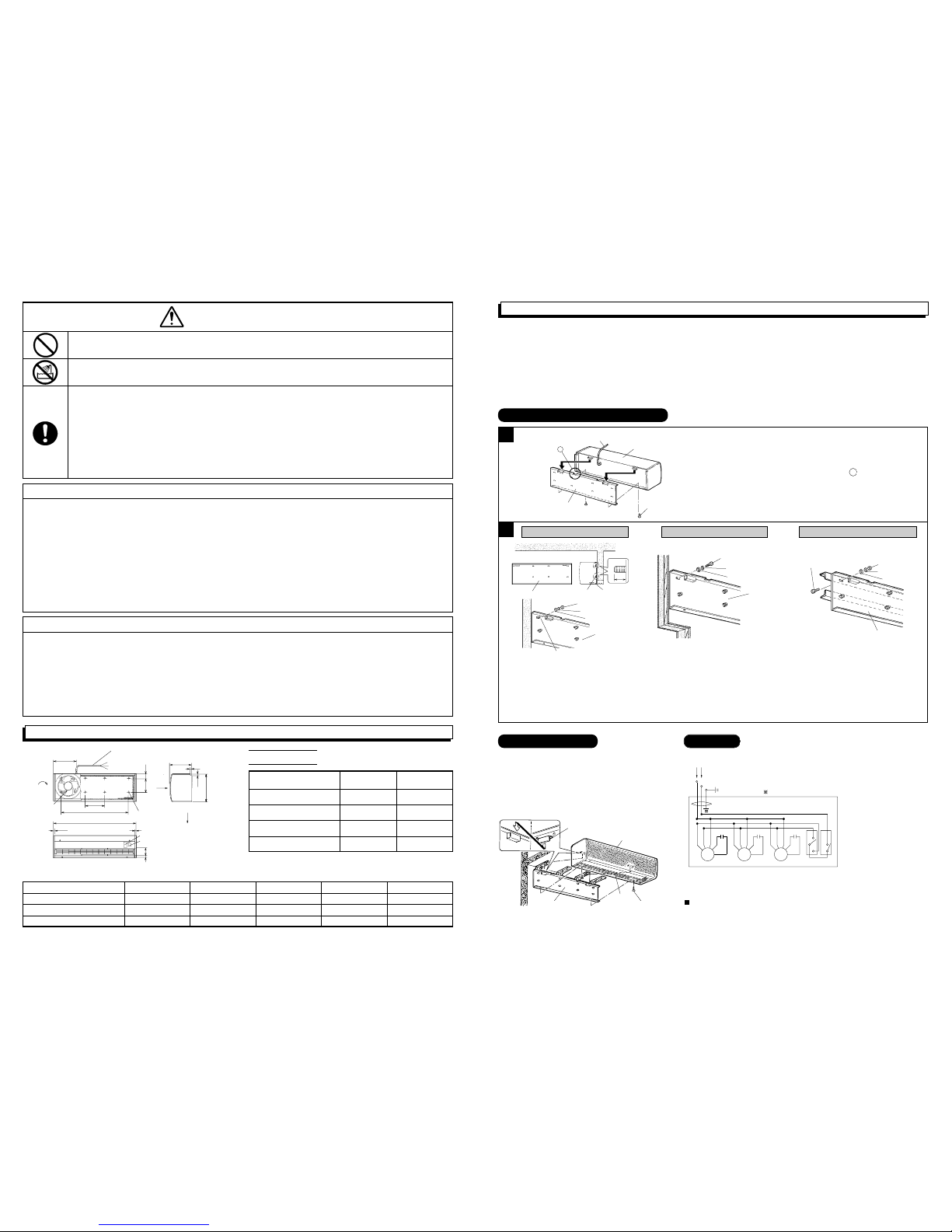
MOTOR MOTOR MOTOR
Pink
Black
Capacitor
Red
Blue
White
Red
Blue
White
Pink
Capacitor
Black
Red
Blue
White
Pink
Capacitor
Black
2
1
3
2
3
HILOON
OFF
Switch
Green/Yellow
Brown
Blue
Source
Black
Red
White
Blue
Carry out ground installation.
The number of motors differs depending on the model.
Installing the Wall mounting plate
Vinyl cabtyre cable
Unit body
Unit body mounting screws
Wall mounting plate
A
– 2– –3–
Installing the Unit
Hook on unit body
Unit body
Installation screws
Air outlet
Wall mounting plate
1.Insert the hook fitting on the back of the unit in
the holder on the wall mounting plate, lowering it
until it stops.
2.Fasten the unit to the wall mounting plate
securely using the 2 screws provided.
¡ Make wiring connections for the parts indicated by bold lines in the connection diagram.
¡ When selecting a motor circuit breaker, use a value of 1.2 to 1.5 times that of the
load current listed in the specifications.
Use 0.75 mm
2
wire, and use a 1.25 mm2or larger ground wire. If multiple units
are operated, connect them to electric wiring which has a capacity that can
handle the total current value.
Wall mounting plate
Recessed Bolts
Wall mounting plate
15
mm
Nut
Spring washer
Washer
Wall mounting plate
Recessed bolts
Wood screws
(supplied by the customer)
Spring washer
Washer
Wall mounting plate
Mounting bolt
(supplied by the customer)
Nut
Spring washer
Washer
Wall mounting plate
(1) Embed recessed bolts so that they protrude
about 15 mm from the wall surface.
The number of recessed bolts is 4 in the case of
the GK3506SA and 8 for the other models.
(2) Fasten the wall mounting plate to the recessed
bolts using the washers, spring washers and
nuts supplied with the air curtain, and tighten
them securely.
If the panel thickness is 20 mm or greater,
mount the wall mounting plate directly on
the wall with the washers and spring
washers supplied with the air curtain, and
wood screws (supplied by the customer).
If the panel thickness is less than 20 mm,
install a reinforcing board (supplied by the
customer) so that the total thickness
becomes 20 mm or greater.
(1) Installation holes have already been made in the
wall mounting plate’s mounting hole positions.
(2) Install the wall mounting plate on the wall
using the washers, spring washers and nuts
supplied with the air curtain and bolts (supplied
by the customer), fastening it securely.
¡ Install the mounting bolts so that they
protrude from the wall mounting plate about
15 mm.
Remove the two mounting screws from the unit body, then
remove the wall mounting plate from the unit body.
Run the vinyl cabtyre cable through the U groove A .
1
2
Mounting on a concrete wall Mounting on a board wall
Mounting on steel beams or steel pillars
Wiring
 Loading...