

Page 1

Mitsubishi Electric Air-conditioner Control System
Centralized Controller
GB-24A
Operation Manual for Initial Setting Web
Contents
1 Introduction ..............................................................................1
1-1 Terms Used in This Manual ..............................................................1
1-2 Computer Requirements ..................................................................1
2 Setting the Operating Environment .........................................2
2-1 Setting the PC IP Address ...............................................................2
2-2 Setting the Web Browser .................................................................4
3 Performing Operations ............................................................6
3-1 Entering the User Name and the Password, and Connecting to the
GB-24A ............................................................................................6
4 Initial Settings ..........................................................................7
4-1 Setting the Current Date and Time ..................................................7
4-2 Setting Basic Information and External Input Functions ..................8
4-3 Group Setting .................................................................................15
4-4 Interlocked Setting .........................................................................17
4-5 Block Setting ..................................................................................18
5 Functions 1 ............................................................................19
5-1 Error mail reports/E-mail communication .......................................19
5-2 Settings for measurement ..............................................................22
6 Functions 2 ............................................................................26
6-1 Limiting the Set Temperature Operating Range .............................26
6-2 Night Mode (Silent Mode) Schedule ..............................................27
7 User Setting ...........................................................................28
8 Registering a License for Optional Functions ........................30
Before using the web browser to set the GB-24A controller, please read this operation
Manual carefully to ensure correct operation.
Retain this manual for future reference.
Page 2
1 Introduction
Special features of Mitsubishi Electric Corporation’s "Centralized Controller GB-24A" are that a PC connected
to a LAN can be used to monitor the operation condition of air conditioners, perform air conditioner operatio ns,
and make initial settings.
The document explains the procedures for performing initial settings for the Centralized Controller GB-24A
using the web browser.
1-1 Terms Used in This Manual
- “Click” refers to positioning the mouse cursor on the object (such as button or folder), pressing down, and
releasing the left mouse button once.
- Unless otherwise specified, the example screen images used in this manual are Windows XP
Explorer 6.0 screen images.
Note: Windows is a registered trademark or trademark of Microsoft Corporation USA in the United States and other countries.
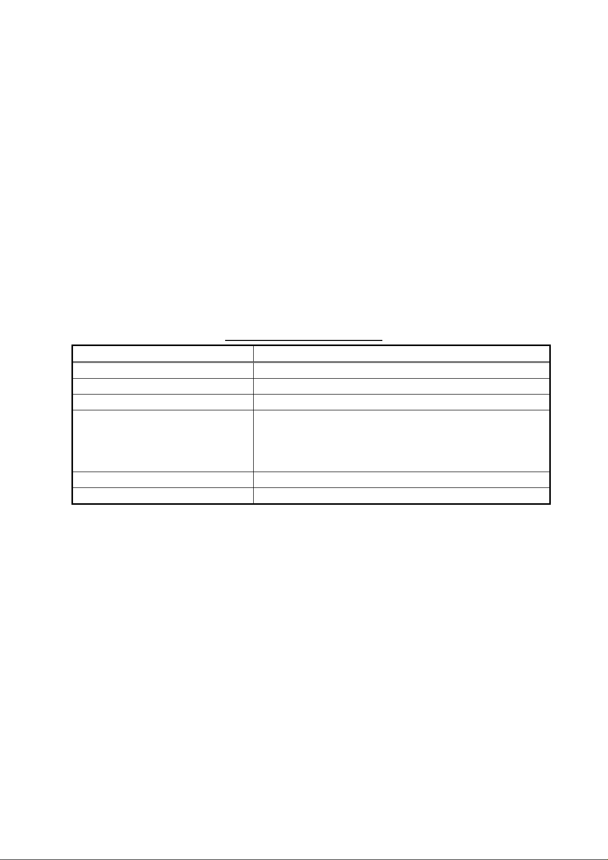
1-2 Computer Requirements
To monitor and operate air conditioners by web browser, computer must include the following requirements.
Table 1-1 Computer Requirements
Item Requirement
CPU
Memory
Screen resolution
Compatible browser
On-board LAN port or LAN card
Other
Note: Microsoft is a registered trademark or trademark of Microsoft Corporation USA in the United States and other countries.
Sun Microsystems and Java are trademarks or registered trademarks of Sun Microsystems Inc. in the United States and/or
other countries.
Pentium 133MHz or faster (300MHz or faster recommended)
64M Bytes or more (128M Bytes or more recommended)
1024 x 768 or higher recommended
®
Microsoft
Note: You must have a Java® execution environment
Note: You can check the Sun Microsystems Java Plug-in version in
Internet Explorer 6.0or later
(Sun Microsystems
“Java Plug-in” in a control panel.
One connector (10BASE-T)
Pointing device such as a mouse
®
Java Plug-in Ver.1.4.2 or later).
®
and Internet
1
Page 3
2 Setting the Operating Environment
PC settings and web browser settings required for using a web bro wser to monitor air conditioner units and
perform operations are explained in the following pages.
2-1 Setting the PC IP Address
Set an IP address on the PC that enables GB-24A to connect via a web browser.
For instance, if the GB-24A IP address is [192.168.1.1], the PC IP address will need to belong to the same
system [192.168.1.101].
If the GB-24A is connected to an existing LAN, ask the LAN administrator to decide what PC IP address to
use.
Note: When using a GB-24A dedicated LAN, it is recommended that the GB-24A main unit be given an IP address
within the range [192.168.1.1] — [192.168.1.40] and the PCs connected to the GB-24A be given an IP
address within the range [192.168.1.101] — [192.168.1.150]
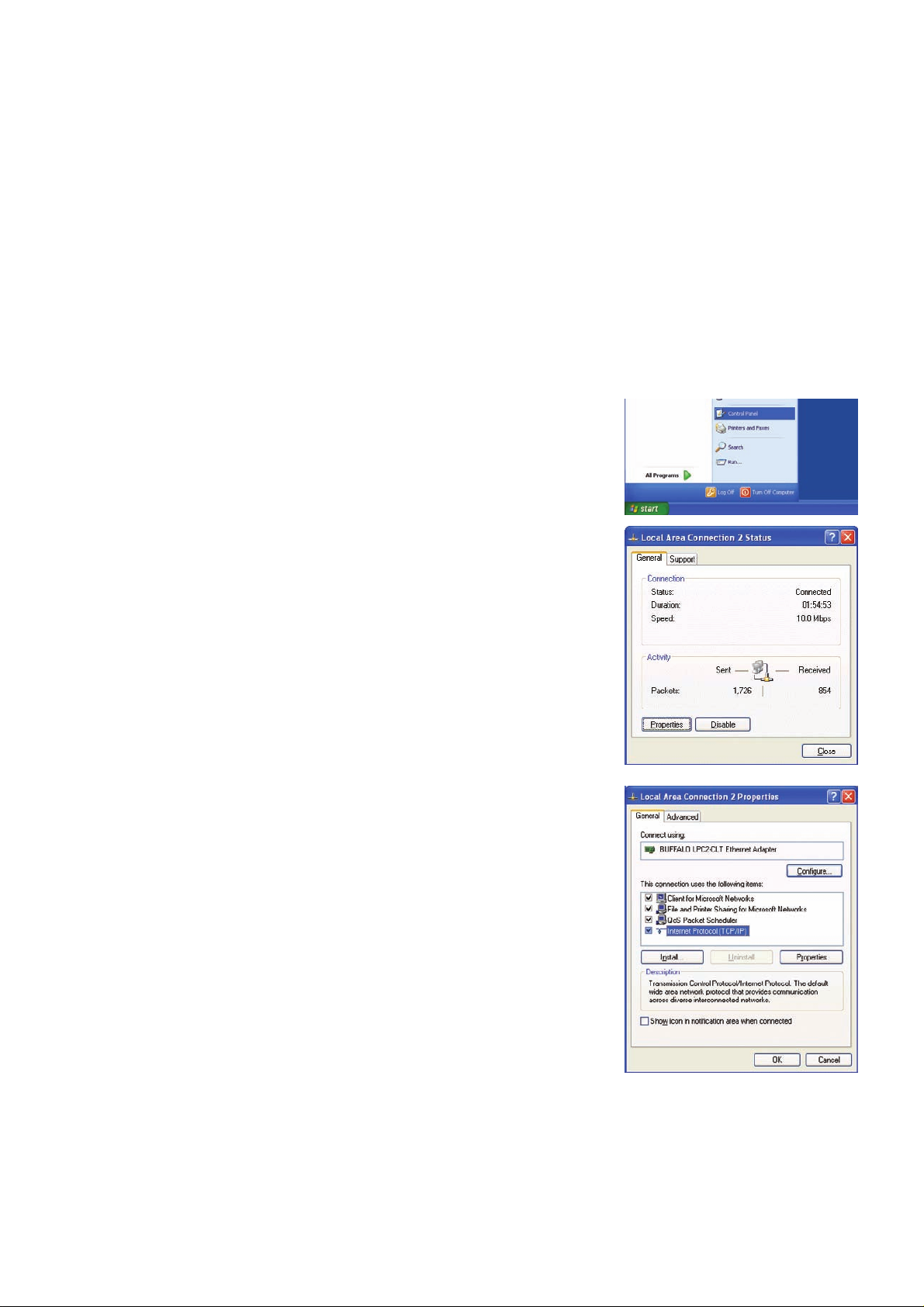
(1) Click on [Control Panel] under [Start] to open the Control Panel.
(2) In the Control Panel window, double click [Network and Dial-up
Connections] and the Network and Dial-up Connections window will
open. Double click on [Local Area Setting] and the [Local Area
Connection Status] dialog will open. Click [Properties].
(3) In the [Local Area Connection Properties] dialog, click [Internet
Protocol] to select it and click the [Properties] button.
2
Page 4
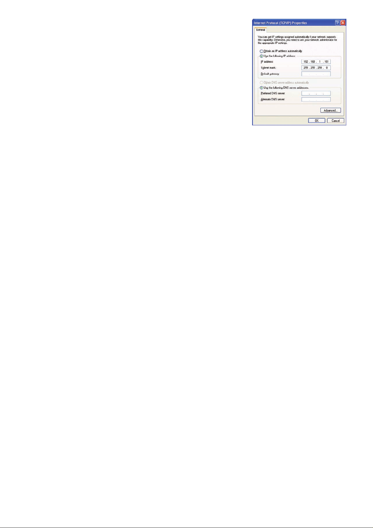
(4) In the [Internet Protocol (TCP/IP) Properties] dialog, click [Use the
following IP address] and enter the IP address (for example,
“192.168.1.101”) that you want to set in the IP address field.
You normally set [255.255.255.0] as the subnet mask.
Note: Ask your LAN administrator to provide the IP addresses and subnet mask.
(5) Click the [OK] button to close this dialog, and then close the other open
dialogs to complete the network setting.
3
Page 5
2-2 Setting the Web Browser
Necessary web browser settings must be performed to enable the web browser to connect to the GB-24A.
Note: The settings and screen images used as examples in this manual are based on Internet Explorer 6.0.
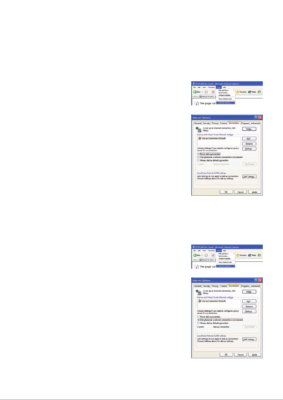
2-2-1 No Internet Connection
Follow the instructions below to make the web browser environment settings when using the PC with no
Internet connection for monitoring and operating the air conditioners.
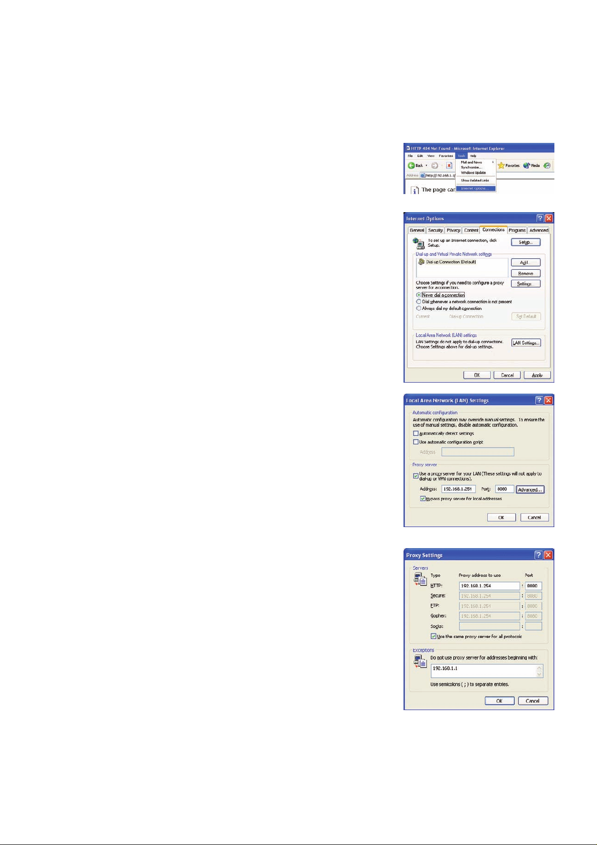
(1) Click the web browser menu item [Tools] and then click [Internet
Options…] to select.
(2) In the [Internet Options] tabbed dialog, click the [Connections] tab to
display.
(3) Select [Never dial a connection] in the Dial-up settings section and
click the [OK] button to close the dialog.
2-2-2 Internet connection using a dial-up
If the PC used for monitoring air conditioners and performing operations is going to connect to the Internet via
a dial-up connection, use the procedure given below to set the web browser environment settings.
By performing these settings, a message will appear asking whether or not to use a dial-up connection when
an Internet connection is necessary. When connecting to the Internet is designed, follow the directions below.
(1) Click the web browser menu item [Tools] and then click [Internet
Options…] to select.
(2) In the [Internet Options] tabbed dialog, click the [Connections] tab to
display.
(3) Select [Dial whenever a network connection is not present] in the
Dial-up settings section and click the [OK] button to close the dialog.
4
Page 6
2-2-3 Connecting to the Internet using a proxy server (Using an existing LAN)
If the PC you use for monitoring air conditioners and performing operations is going to acce ss the Internet via
proxy server by connecting to an existing LAN such as a LAN within your company, use the procedure given
below to set the web browser environment settings.
By performing these settings, your PC will connect to a proxy server only when connecting to the Internet.
(1) Click the web browser menu item [Tools] and then click [Internet
Options…] to select.
(2) In the [Internet Options] tabbed dialog, click the [Connections] tab to
display.
(3) Select [Never dial a connection] in the Dial-up setting section.
(4) Click the [LAN Setting . . .] button in the Local Area Network (LAN)
settings section to display the Local Area Network (LAN) Settings
dialog.
(5) In the Local Area Network (LAN) Settings dialog, check [Bypass proxy
server for local addresses] and click the [Advanced...] button.
(6) Enter the IP address for the GB-24A (e.g. 192.168.1.1) in the
Exceptions field of the Proxy Setting dialog and click the [OK] button to
close the dialog and then close the other open dialogs to complete the
setting.
Note: If connecting to more than one GB-24A, you can specify multiple IP addresses
like [192.168.1.1; 192.168.1.2], however, it is also possible to use the asterisk
(*) and specify [192.168.1*].
5
Page 7
3 Performing Operations
Text below explains how to connect to the GB-24A and how to perform various settings.
Note: If the GB-24A is restarted due to a power interruption etc., wait until the screen on the GB-24A main unit displays the normal
operation screen (it takes several minutes before the normal operation screen is displayed) before using a web browser to
access the GB-24A. If access is attempted while the GB-24A is still starting up, the most recent data might not be displayed
or communication errors could occur.
Note: Default IP address of GB-24A is "192.168.1.1". (Factory setting)
3-1 Entering the User Name and the Password, and Connecting to
the GB-24A
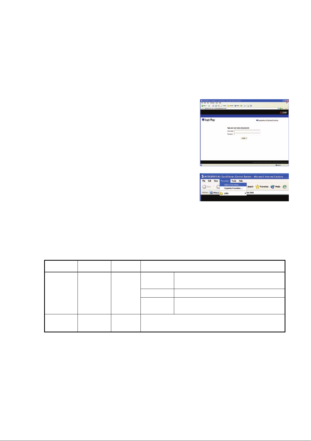
(1) Enter the web page address in the address field of the web
browser as follows:
http:// [IP address of the GB-24A]/g-50/ administrator.html
Press the [Enter] key on the keyboard. A screen appears for login.
Note: For example, type “http://192.168.1.1/g-50/administrator.html” if the
GB-24A IP address is [192.168.1.1].
(2) To make connection easier for the next time, click the web
browser menu item [Favorites], click [Add to Favorites], then add
the address to the Favorites folder. Once this address is added to
the Favorites folder, it is not necessary to input the address of (1).
Simply select it from the Favorites folder and the GB-24A page will
appear.
(3) Enter the user name and the password in the login screen, and click the [Login] button. A screen will
appear in which various setting are made. Procedures for making proper settings on each screen will be
explained in the following pages.
The table below shows the default user names and passwords for maintenance users and managers, as
well as available functions.
User
Default
user name
Default
password
Available functions
Initial settings
Maintenance
user
manager administrator admin
Note: The user name and the manager’s password are the same as those of the manager of the Web for monitoring/operation.
Note: Maintenance users can make available to the administrator only the information necessary for normal operation (group
name setting etc.)
Note: It is recommended to change the user name and password, so users other than the manager are not permitted to change
the settings.
initial init
Functions 1 E-Mail, Measurement
Functions 2
Out of the functions listed above, the items to which access rights have been
given on the user settings screen are available. (Refer to Chapter 7 "User
Setting.")
Date and Time, Basic System, Groups, Interlocked
LOSSNAY, Blocks
Set Temperature Range Limit, Night Mode
Schedule
6
Page 8
4 Initial Settings
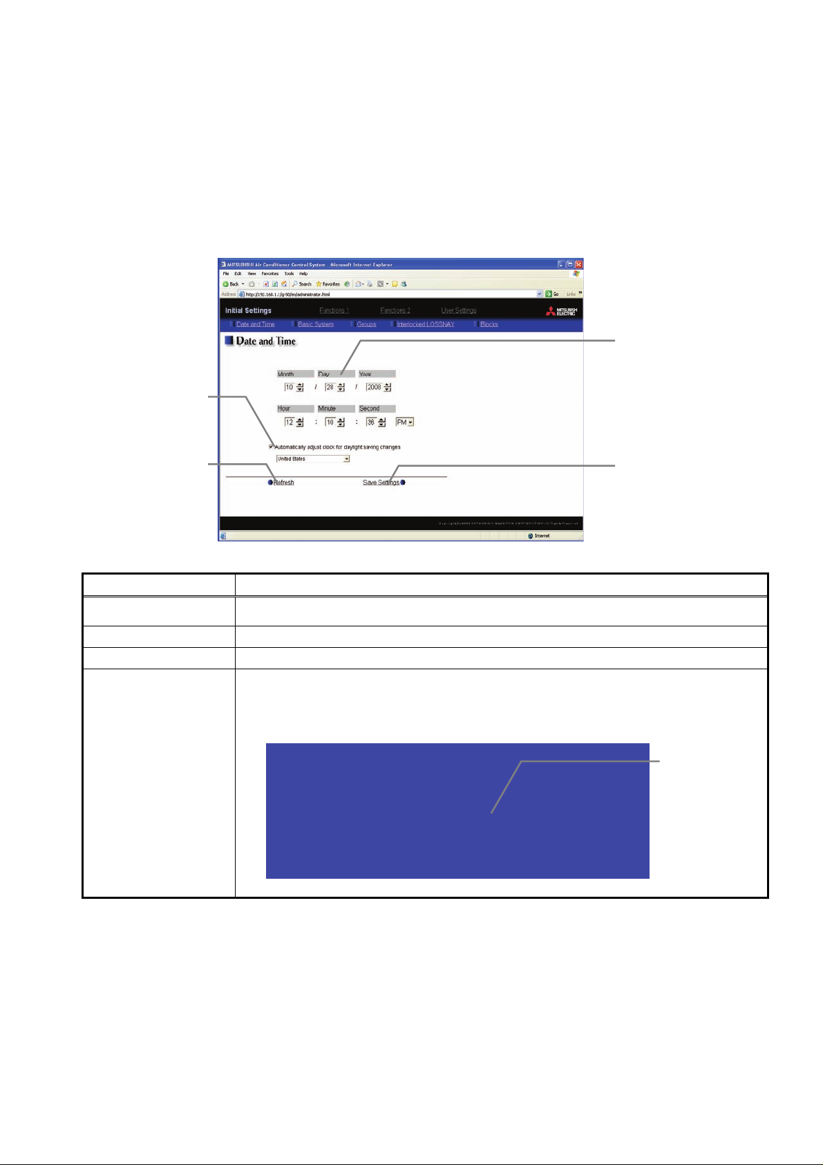
4-1 Setting the Current Date and Time
Click [Initial Settings] in the menu, and [Date and Time] screen will appear on the screen. Enter the current
date and time, and then press the [Save Settings] button to send the current date and time to GB-24A.
Note: If the user logs in as a manager, the operations may be prohibited. (Refer to Chapter 7 "User Setting.")
Note: When the time is set on this screen, the setting will be applied to all units on M-NET system.
Note: When the DIDO controller (PAC-YG66DCA), AI Controller (PAC-YG63MCA), or PI Controller (PAC-YG60MCA) is newly
connected, set the time of the connected controller on this screen.
Summer time setting
Click to set the daylight saving
time.
Acquires the current Date and
Time from G-B24A.
Refresh
Item Description
Current date/time
Save Settings Click the [Date/Time Set] button to set the current date and time.
Refresh Acquires the current Date and Time from GB-24A.
Enter the current date and time.
For the date, use the format [day - month - year].
Click and tick the "Automatically adjust clock for daylight saving changes" box to
adjust the daylight saving time automatically, and select the applicable country.
Note: If the applicable country is not in the selection bar, select "Custom Settings". Click "Custom
Settings" button that will appear on the right to set the daylight saving time.
Summer time setting
Custom Setting Screen
Current date/time
Enter the current date and
time here.
Save settings
Click to set the current date
and time.
Daylight saving
date and time
Set the daylight
saving time.
7
Page 9
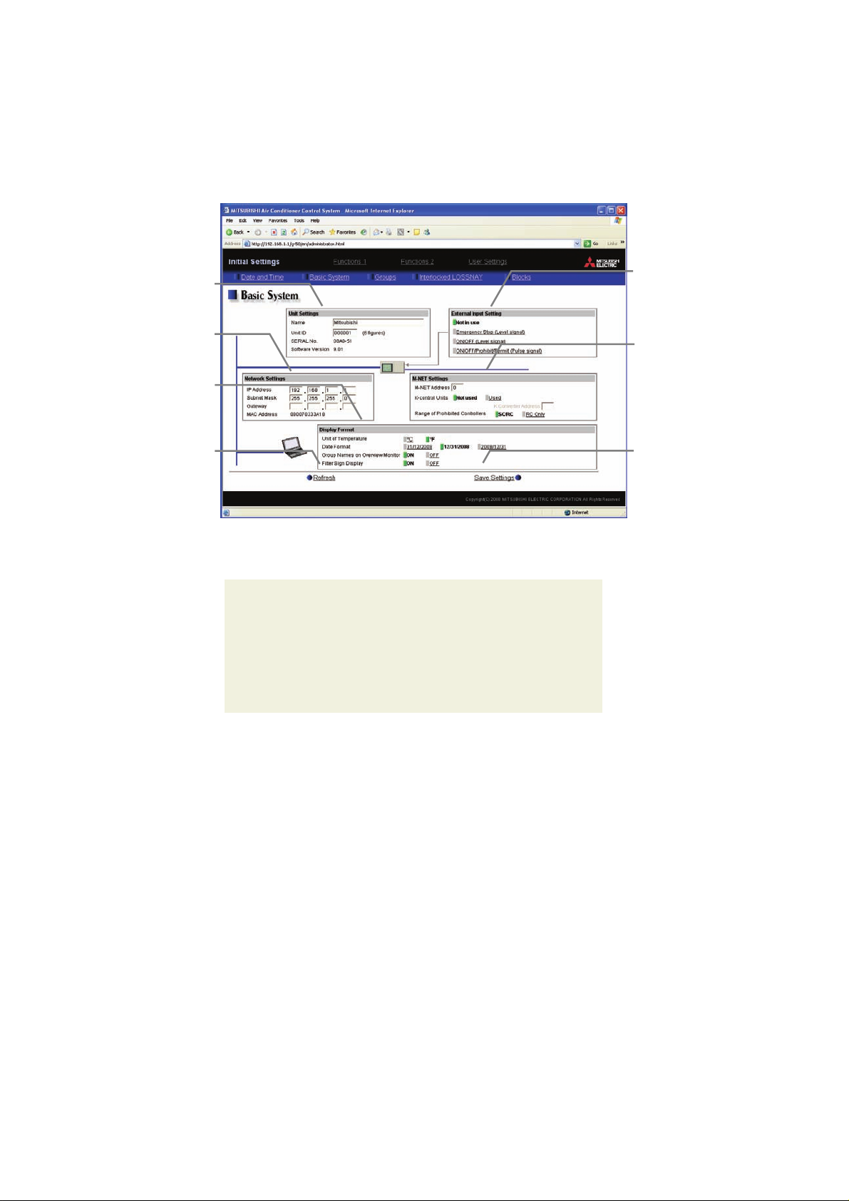
4-2 Setting Basic Information and External Input Functions
Display the page needed to perform the GB-24A basic setting by clicking [Initial Settings]-[Basic System] in the
setting menu pane. On this page, set the GB-24A unit name, network, and M-NET. Click [Save Settings] to
save the set data to the GB-24A. After the setting data are sent to the GB-24A, a message will appear asking
whether or not to restart the GB-24A. Click [OK] to restart the GB-24A and apply the changes.
Note: If the user logs in as a manager, the operations may be prohibited.
Set the GB-24A IP address
and subnet mask.
Set the items related to the
screen display on the Web.
Read setting data from G-24A.
Unit Setting
Set the GB-24A name
and unit ID.
Network Setting
Display Format
Refresh
4-2-1 GB-24A Unit Setting
External Input Setting
M-NET Setting
Save Settings
Set the GB-24A external input
setting.
Set the GB-24A M-NET
address, presence/absence of
K-Control units and range of
prohibited controllers.
Send setting data to GB-24A.
In “Unit Settings” on the [Basic System] screen, set the GB-24A name and unit ID.
(1) Enter the GB-24A unit name in the [Name] field. A maximum of 40 alphanumeric or symbol characters can
be entered. The name set here is used on the display screen of the software that controls multiple GB-24A
units and for the name of the sender in the body of error messages.
Note: The following characters cannot be used in the name: < > & " '
(2) Enter the GB-24A unit ID in the [Unit ID] field. Six numbers must be included. Use this setting when it is
necessary to control multiple GB-24A units with unit IDs. The unit ID that is entered will be used on the
display screen of the software that controls multiple GB-24A units and for the sender ID in the body of error
messages.
(3) When [Refresh] is clicked, the GB-24A production ID will appear in the [SERIAL No.] field and the GB-24A
software version will appear in the [Software Version] field.
8
Page 10
4-2-2 M-NET Setting
In "M-NET settings", set the GB-24A M-NET address, presence/absence of K-Control model, and range of
prohibited controllers.
(1) Enter the GB-24A M-NET address in the [M-NET Address] field. Normally, [0] should be entered.
(2) When K-Control air conditioners are connected, click [Used] in the [K-Control Units] field and enter the
M-NET address of K transmission converter in the [K Converter Address] field.
Note: K transmission converter cannot be used. Select “Not used” for the K-control Units setting in the M-NET Settings window.
(3) In the local control prohibit settings, select both subordinate system controllers and remote controllers, or
only remote controllers. Click [SC/RC] to prohibit operation from both subordinate system controllers and
remote controllers, and click [RC Only] to prohibit operation from only remote controllers.
Note: Normally, [SC/RC] should be selected.
4-2-3 Network Setting
It is assumed that the GB-24A will be used on a private network.
In “Network Settings”, set the GB-24A IP Address, Subnet Mask and Gateway address. If connecting to the
GB-24A via a permanent LAN, consult with the network administrator before setting these addresses.
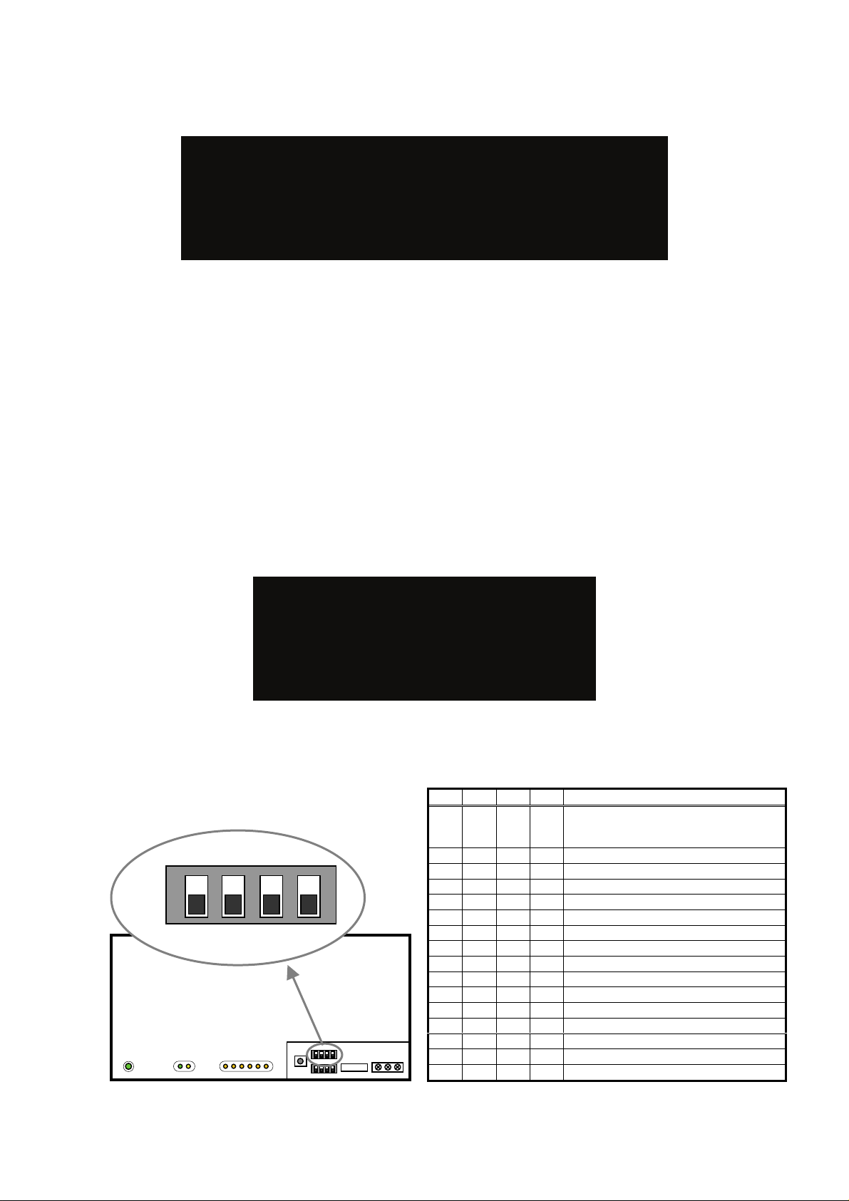
[Simple IP address setting of GB-24A]
The IP address that is set on the dip switch (SW2) on GB-24A main body has the priority. (Settings are shown below.)
When activating the value that is set on the initial setting Web, set all the switches on SW2 to OFF.
When the number of GB-24A units is 15 or less, it is recommend to set the IP address using the dip switch (SW2) on
GB-24A main body.
ON
OFF
Note: After changing the dip-switch settings, reset the power of GB-24A to activate the changes.
SW 2
1 2 3 4
SW1/2/3 EXT.I/O M-NET
123456 LINK/ACT LAN POWER
1 2 3 4 IP Address
OFF OFF OFF OFF
OFF OFF OFF ON 192.168.1.1
OFF OFF ON OFF 192.168.1.2
OFF OFF ON ON 192.168.1.3
OFF ON OFF OFF 192.168.1.4
OFF ON OFF ON 192.168.1.5
OFF ON ON OFF 192.168.1.6
OFF ON ON ON 192.168.1.7
ON OFF OFF OFF 192.168.1.8
ON OFF OFF ON 192.168.1.9
ON OFF ON OFF 192.168.1.10
ON OFF ON ON 192.168.1.11
ON ON OFF OFF 192.168.1.12
ON ON OFF ON 192.168.1.13
ON ON ON OFF 192.168.1.14
ON ON ON ON 192.168.1.15
IP address set by Initial Setting Web
Note: Default IP address "192.168.1.1".
(Factory setting)
9
Page 11

Note: If the IP address of GB-24A is forgotten, check the IP address that is registered on the monitoring PC (Web) in use. GB-24A
can be started temporarily by using a specified IP address. It is recommended to paste a sticker with the IP address on the
unit, so that the IP address of GB-24A can be available at all times.
10
Page 12

4-2-3-1 Settings for when the GB-24A is connected to a dedicated LAN
(1) Enter the GB-24A IP address in the [IP Address] field.
Note:The recommended IP address for the G-50A is [192.168.1.1].
[Example of IP address setting]
10BASE-T LAN straight cable
GB-24A No. 1
Note: Some hubs have a dedicated port for connection with another hub.
Connect the G-50A and Web Monitor PC to the normal ports.
(2) Enter the GB-24A subnet mask in the [Subnet Mask] field. Normally, you should enter [255.255.255.0].
(3) When monitoring remotely or sending error mail via a dial-up router, enter the router IP address in the [Gateway]
field.
Leave the gateway address blank when not connecting via a dial-up router.
[Example of a Remote Monitoring System]
Telecommunication Network
Dial-up router
IP: 192.168.1.254
IP Address :192.168.1.1
Subnet Mask :255.255.255.0
G/W Address :192.168.1.254
GB-24A
Web Monitor PC
IP Address :192.168.1.101
Subnet Mask :255.255.255.0
G/W Address :Blank
Note: It is recommended to set the dial-up router IP address to [192.168.1.254]. Refer to the dial-up
router instruction manual for details of how to set the IP address.
Note: It is necessary to connect a modem (analog type or ISDN type) between the dial-up router
and telephone line when using a dial-up router that does not have a built-in modem.
Note: Use a security device such as a VPN router when connecting the GB-24A to the Internet to
prevent unauthorized access.
Hub
Web Monitor PC
192.168.1.101 192.168.1.1
Dial-up router, cellular phone etc.
Web Monitor PC
11
Page 13

4-2-3-2 Settings for when the GB-24A is connected to an existing LAN
When connecting the GB-24A to an existing LAN, consult with the network administrator who is responsible for
the LAN before setting the IP address, subnet mask, or gateway address.
[Example of a Permanent LAN System]
Backbone LAN (private network)
Gateway Gateway
IP: 192.168.1.250 IP: 192.168.2.250
GB-24A
IP Address :192.168.1.1
Subnet Mask :255.255.255.0
G/W Address :192.168.1.250
Receive from the LAN
administrator.
IP Address :192.168.1.101
Subnet Mask :255.255.255.0
G/W Address :192.168.1.250
Web Monitor PC
Receive from the LAN
administrator
.
IP Address :192.168.2.51
Subnet Mask :255.255.255.0
G/W Address :192.168.2.250
Web Monitor PC
4-2-4 External Input Setting
In the External Input Setting menu, set the GB-24A external input function. By using external input functions, it
is possible to stop and run multiple air conditioners connected to the GB-24A via the separately sold external
I/O adapter for G-24A (Model: PAC-YG10HA) using level signals and pulse signals.
(1) Select [Not in use] when not using the external input function.
(2) Selecting [Emergency stop (Level signal)] makes it possible to stop multiple units by using a level signal.
While this stop operation is being performed, operations such as running or stopping units are prohibited
on the GB-24A unit or remote control.
(3) Selecting [ON/OFF (Level signal)] makes it possible to run or stop multiple units using a level signal. In this mode,
all air conditioner units connected to the G-50A will be run or stopped and run/stop operations will be prohibited
on the GB-24A unit or remote control.
Connection to G-24A (CN2)
1
2
3
4
5
6
7
8
9
Connection to G-24A (CN2)
1
2
3
4
5
6
7
8
9
Emergency stop/normal
DC 12V
Run/Stop
DC12V
Contact ON
Contact OFF
Normal
Emergency
Stop
Normal
Contact ON
Contact OFF
Stop Run Stop
12
Page 14

(4) Selecting [ON/OFF/Prohibit/Permit (Pulse signal)] makes it possible to use pulse signals to run multiple
units, stop multiple units, prohibit local operation and permit local operation. In this mode, it is possible to
freely operate the remote control except during the pulse signal input.
1
2
3
4
5
6
7
8
9
Connection to G-50A (CN2)
DC12V
Run
Stop
Prohibit
Permit
:Pulse generator
Run
Contact ON
Contact OFF
0.5 - 1.0 Seconds
Stop
Contact ON
Contact OFF
Stop
StopRun
Prohibit
Permit
Contact ON
Contact OFF
Contact ON
Contact OFF
Permit
0.5 - 1.0 Seconds
Prohibit
Permit
13
Page 15

4-2-5 Setting the Display Format
Set the items related to the screen display in the [Display Format] field.
(1) In the [Unit of Temperature] section, select between [
(2) In the [Date Format] section, select the display order of year/month/day. The date will be displayed in the
selected order on the Web screen or on the mail screen.
(3) In the [Group Names on Overview Monitor] section, select [ON] to display the group name under the icon
on the [Monitor / Operation (Overview)] screen and select [OFF] not to.
Note: Up to 8 letters are displayed under the icon. To display all letters, move the cursor to the icon.
With the display of group names Without the display of group names
(4) In the [Filter Sign Display] section, select whether to display the filter sign. Select [ON] to display the filter
sign and [OFF] not to.
When the filter sign display is set to “OFF,” the filter sign on neither the LCD of the GB-24A nor the monitor
screen on the Web browser will appear, even when the indoor unit detects a filter sign.
If the filter is regularly cleaned and the filter sign display is unnecessary, set it to [OFF].
ºC] and [ºF] as the unit of temperature.
14
Page 16

4-3 Group Setting
f
A
Display the page needed to register the group of air conditioners or general equipment to be connected to the
G-50A and to set the group name by clicking [Initial Settings]-[Groups]. On this page, you perform the basic
setting such as the GB-24A unit name, network setting and M-NET setting. Click [Set to GB-24A] to send
setting data to the GB-24A.
Note: If the user logs in as a manager, some of the operations may be prohibited.
Note: A contact on the genera interface device is regarded as one unit. The number of units that can be connected to GB-24A is
up to 24.
Note: Air-conditioners and general equipment cannot be in the same group.
Note: Remote controllers or system controllers cannot be connected to general equipment.
Group numbers will be
Group name for web
The group names to be used on
the Web screen are entered
Group name for LCD o
Note:Setting not required
Read setting data from
4-3-1 Setting the Group Name
Group No.
displayed here.
here.
the GB-24
Refresh
GB-24A.
Air Conditioner and general
equipment
Register the air conditioner
and general equipment to be
connected here. Click to bring
up the registration screen.
System Controller
Registration
Register the system
controllers to be connected
here. Click to bring up the
registration screen.
Remote Controller
Registration
Register the remote
controllers to be connected
here. Click to bring up the
registration screen.
Save Settings
Send setting data to GB-24A.
Registration
(1) In the [Group Name for Web] field on the screen, register the group name to be displayed on the Web
screen, using a name consisting of no more than 20 characters.
Note: The following characters cannot be used in the group name: < > & " '
(2)
It is not necessary to set the Group name for LCD.
4-3-2 Registering air conditioner units in the group
(1) To register air-conditioners, clicking the [Air Conditioner and
General Equipment Registration] field next to each group in the
[Groups] screen will bring up the [Select Unit Addresses] screen.
Click on the numbers corresponding to the units to be registered.
All selected units will be shown with a yellow-green background.
To cancel the selection, click on them again. Deselected items will
be shown with a gray background.
Note: A maximum of 16 air conditioner units can be registered in one group.
Note: To change the registered units to air-conditioners in the group in which
general equipment is registered, disconnect the general equipment first.
(2) To change the icon, click the right or left arrow.
15
Page 17

(3) To register remote controllers in a group, click on the [Remote
Controller Registration] field to display the [Select Unit Addresses]
screen, and click on the numbers corresponding to the units to be
registered. The ones that are selected will be shown with a
yellow-green background. To cancel the selection, click on them
again. Deselected items will be shown with a gray background.
Note: A maximum of 2 remote controls can be registered in one group.
Note: MA remote controls do not need to be registered to a group.
(4) To register system remote controllers in a group, click on the
[System Controller Registration] field to display the [Select Unit
Addresses] screen, and click on the numbers corresponding to
the units to be registered. The ones that are selected will be
shown with a yellow-green background. To cancel the selection,
click on them again. Deselected items will be shown with a gray
background.
Note: The combined number of system controllers and remote controls cannot
exceed four.
4-3-3 Registering general equipment in the group
(1) To register general equipment in a group, click on the [Air
Conditioner and General Equipment Registration] field to
display the [Select Unit Addresses] screen, and select the
[General Equipment (via PAC-YG66DCA)].
Click the device No. of the general interface device
(PAC-YG66D) that is connected to the general equipment
to be registered. The selected No. will be displayed with a
red frame (selected state), and select the contact No. to
which the general equipment is connected.
To disconnect the general equipment, select the interface
device No., and click the contact No. that has been selected. The No. will be displayed in gray (unselected
state).
Note: A maximum of 16 general equipment can be registered in one group.
Note: To change the registered units to general equipment in the group in which air-conditioners are registered, disconnect the
air-conditioners first.
(2) To change the icon, click the right or left arrow.
(3) In the [Allow Operation] section, select whether to enable or disable the ON/OFF operation on the Web
browser operation screen. Select [In batch and on individual group] to enable only when the collective
operation is performed. Select [On individual group] to enable in each group. Select [No operation (Monitor
only)] to disable.
(4) In the [Monitor] section, select whether to display I/P to or from the general equipment on the monitor
screen.
16
Page 18

4-4 Interlocked Setting
Y
To interlock the operation of LOSSNAY with the run/stop status of the indoor units, click on [Initial
Settings]-[Interlocked LOSSNAY] in the menu to bring up the Interlocked LOSSNAY screen, and enter the
interlock conditions. Click [Save Settings] to send setting data to the GB-24A.
Note: If the user logs in as a manager, the operations may be prohibited.
Interlocked LOSSNA
Registration
Register the interlocked
ventilation equipment here.
Click to bring up the registration
screen.
Read setting data from
Refresh
GB-24A.
(1) Click in the Interlocked LOSSNAY registration field to display the
[Select a Unit Address] screen, and click on the numbers
corresponding to the units to be registered. The ones that are
selected will be shown with a yellow-green background. To cancel
the selection, click on them again. Deselected items will be sho wn
with a gray background.
(2) Click on the Interlocked Indoor Unit Registration field to display
the [Select Unit Addresses] for the indoor units, and click on the
numbers corresponding to the units to be registered. The ones
selected will be highlighted with a yellow-green background. To
cancel the selection, click on them again. Deselected items will be
shown with a gray background.
Note: A maximum of 16 indoor units can be registered to operate with
one ventilator.
Interlocked Indoor Units
Registration
Register the indoor units to
which LOSSNAY units are
interlocked here. Click to bring
up the registration screen.
Save Settings
Send setting data to GB-24A.
17
Page 19

4-5 Block Setting
By performing block settings, multiples of air conditioner groups can be collectively monitored or operated from
the Web. Bring up the Block Setting screen by clicking [Initial Settings]-[Blocks] in the menu, and register the
groups in the block to utilize these features. Click [Save Settings] to send setting data to the GB-24A.
Note: If the user logs in as a manager, some of the operations may be prohibited.
Register the block name to be
displayed on the Web screen
Block Name
here.
Read setting data from
Refresh
GB-24A.
Group Registration
Register the groups to be
included in the block here.
Save Settings
Send setting data to GB-24A.
4-5-1 Registering a block name
In the [Block Name] field on the screen, register the block name to be displayed on the Web screen, using a
name consisting of no more than 20 characters
Note: The following characters cannot be used in the group name: < > & “ ‘
4-5-2 Registering a group in a block
Click on the Group Registration field to display [Select Groups], and
click on the numbers corresponding to the groups to be registered.
The ones that are selected will be shown with a yellow-green
background. (Putting a cursor on the group number will display the
group name.) To cancel the selection, click on them again.
Deselected items will be shown with a gray background.
18
Page 20

5 Functions 1
5-1 Error mail reports/E-mail communication
Click on [Functions 1] – [E-Mail] in the menu to open the [E-mail] window and make necessary settings to
perform remote monitoring via mail, using error mail report or the maintenance tool.
Click [Save Settings] to send setting data to the GB-24A.
Note: The use of the error mail report function requires a separate license registration.
Confirm on the license registration screen (Ch8) that the license registration has been completed.
Note: If the user logs in as a manager, the operations may be prohibited.
Mail Server Information
Set the mail server/DNS server
information here.
Mail Communication
Set the address of the mail
Read setting data from
Setting
recipients here.
Refresh
GB-24A.
E-Mail settings of GB-24A
The E-mail settings of GB-24A
are set here.
Error Mail Settings
Set the error mail destination
here.
Save Settings
Send setting data to GB-24A.
5-1-1 Entering the E-Mail Information for the GB-24A
Enter the E-mail information provided by either the ISP or the
LAN administrator.
Note: When sending E-mail via an ISP, a user contract with the ISP is
required.
Make necessary settings based on the functions that are to be used, using the table below as a reference.
Table 5-1 Items that Require Settings to Be Made (E-Mail Settings of GB-24A)
Functions
Items
Mail Address V V V V
User ID V V V
Password V V V
Interval of checking incoming
mails
Authentication
Error Mail Report Mail Communication
No SMTP
V V
Uses SMTP
Authentication
No SMTP
Authentication
Uses SMTP
Authentication
19
Page 21

5-1-2 Setting the Mail Server Information
Enter the mail server information provided by either the ISP or
the LAN administrator.
Either the IP address or the host name (server name) can be
entered in the mail server field.
Make necessary settings depending on the functions to be used, using the table below as a reference.
Table 5-2 Items that Require Settings to Be Made (Mail Server Information)
Functions
Items
Outgoing Mail Server (SMTP)
SMTP Authentication V V
Incoming Mail Server (POP3)
DNS Server (Primary)
DNS Server (Secondary)
Authentication
IP Address or
Error Mail Report Mail Communication
No SMTP
V
Host Name
*1
(V)
*1
(V)
*1: Not necessary if the IP address is used as the mail server address.
Uses SMTP
Authentication
V
Host Name
V
V
No SMTP
Authentication
V
IP Address or
Host Name
V
IP Address or
Host Name
*1
(V)
(V)*1
5-1-3 Setting the Error Mail Destinations
(1) Enter the title of the error mail that will be sent from GB-24A
in the [Mail Title] field. The title may contain a maximum of
40 characters.
Note: The following characters cannot be used in the mail title:
< > & “ ‘
(2) Choose the error type out of the following: [Unit Error], [Preliminary Unit Error], [Communication Error],
[General Equipment] and [User Setting 1] through [User Setting 6]. Then enter the mail address of the
recipient of the error mail.
(3) To send error messages only upon occurrences of certain
errors, click the User Setting button that appear when "User
Setting 1" through "User Setting 6" are selected, and
register the error codes to be reported in the user settings.
A maximum of 20 error codes can be set for each user
setting. In addition to specific error codes such as [1302] or
[6607], codes such as [10**] or [12**] can also be used. If
[10**] is set, for example, error mail will be sent upon an
occurrence of any type of errors between [1000] and [1099].
If error codes are set on this screen, confirm that the
address of the recipient is registered.
(4) Do not select "General Equipment."
Uses SMTP
Authentication
V
Host Name
V
IP Address or
Host Name
V
V
20
Page 22

5-1-4 Setting the Addresses of the Recipient
To monitor and operate the unit with the maintenance tool via
mail from a remote location, enter the mail address of the
receiver in the [Mail Communication Setting].
A maximum of 10 addresses can be registered.
E-mail communication is possible only with the recipients
whose addresses are registered on this screen.
5-1-5 Mail format
Error mails are sent in the format shown below.
Item Format Remarks
Mail title Set title Refer to 5-1-3 (1) for the setting of mail title.
From GB-24A unit name and unit ID
Date dd/MM/yyyy hh:mm:ss
When an error occurs on air conditioners and
Error unit
Error code 4-digit error
Status
general equipment
- M-NET address of the error source
"
Occurrence" or "Recovery"
From:Mitsubishi Building(000001)
Date:11/09/2005 16:32:12
Error unit:065
Error code:1302
Status:Occurrence
Refer to 4-2-1 for the setting of GB-24A unit
name and unit ID.
Date of error
Note: The date format set in section 4-2-5 will be
When an error occurs on air conditioners
When an error occurs on general equipment
Error status
applied.
Note: When an error occurs on the general
Refer to the service manual for each unit.
0091:General equipment error
equipment that is connected via DIDO
controller, M-NET address of the DIDO
controller will be sent. (which means an error
occurs on one of the general equipment that is
connected to the DIDO controller)
21
Page 23

5-2 Settings for measurement
y
f
r
r
r
f
f
r
To measure the temperature or the amount of electricity, click the [Function1]-[Measurement] in the menu, an d
open the Measurement screen. Settings for controllers used for measurement can be made.
After the settings are made, click [Save Settings] to send setting data to GB-24A.
Note: To use the measurement data for energy saving (peak cut) control, the energy saving (peak cut) license must be registered.
Check that the license have been registered properly on the license registration screen (refer to chapter8). It is not
necessary to register the license to display the present measurement data or trend graph or to send an error mail.
Note: If the user logs in as a manager, some of the operations may be prohibited.
Selection of items to be
Select the items to be measured
between by sensors (such as
temperature/humidity) or b
meters (such as amount o
Unit address will be displayed
Select the separator character
for CSV file.
Selection of decimal point
Selection of separator
Select the decimal point
Select the data saving interval.
Read setting data from GB-24A.
5-2-1 Registering AI controllers for temperature/humidity sensors
measured
electricity).
Address
here.
characte
characte
character.
Trend interval
Refresh
Setting details
Set the details for measurement.
Scroll bar
Switch the address.
Mail sending settings
Set the Type of E-Mail, Mail
Subject, and E-Mail Address.
Save Settings
Send setting data to GB-24A.
System settings for measurement sensors can be made. Up to two temperature/humidity sensors can be
connected to one AI controller.
Temperature/humidity selection
Items to be
measured
Address
Setting Details o
sensor 1
Setting Details o
sensor 2
(1) Use the scroll bar, and select the address to which the AI controller (PAC-YG63MCA) is connected.
(2) Select the icon of the AI controller (
Note: To disconnect the AI controller, click the icon of the AI controller that has been selected. The icon will be in unselected state.
(3) Enter the name of the sensor.
(4) Select either the temperature icon (
(5) Enter the measurable range of the temperature or of the humidity.
Note: When the Pt sensor is connected, the range must be between -30ºC and +60ºC. When the sensors other than the Pt
sensors are connected, enter the ranges that are described in the operation manuals.
(6) To receive an e-mail when the temperature or the humidity exceeds a certain value, set the upper/lower
limit alarm values (occurrence, recovery).
Note: To avoid repeating occurrence and recovery, it is recommended that the difference between the occurrence value and the
recovery value is approx. 1ºC.
Sensor name
Measurable range
Scroll ba
) in the column of items to be measured.
) or the humidity icon ( ).
Settings for upper/lowe
limit alarm
Upper limit
(occurrence)
Upper limit
(recovery)
Upper limit
(recovery)
Lower limit
(occurrence)
22
Page 24

5-2-2 Adjusting the measured temperature/humidity values
f
f
f
f
r
When the adjustment of the measured values is necessary because of the location of the sensor, follow the
procedures below.
Note: The present measurement value or the adjusted measurement value are not displayed until the connection settings of the
AI controller are completed.
When the AI controller is registered for the first time, click the [Save Settings] button to send setting data, and click
[Function 1]-Measurement] to display the screen again.
(1) Click the [Set offset] in the [Setting details] section.
(2) Select the adjustment value in the [Offset] pulldown
or select the value to be desired in the [Modified
value] pulldown.
The adjustable range is between -10.0ºC and
+10.0ºC (-18.0ºF and +18.0ºF), -10.0% and +10.0%.
5-2-3 Registering PI controllers for measurement by meters
System settings for measurement meters can be made. Up to four meters can be connected to one PI
controller (PAC-YG60MCA).
Items to be
measured
Address
Setting details o
sensor 1
Setting details o
sensor 3
(1) Use the scroll bar, and select the address to which the PI controller is connected.
(2) Select the icon of the PI controller (
) in the column of items to be measured.
Meter name
Value per pulse
Measurement unit
Setting details o
sensor 3
Setting details o
sensor 4
Scroll ba
Note: To disconnect the PI controller, click the icon of the PI controller that has been selected. The icon will be in unselected state.
(3) Enter the name of the meter.
(4) Enter the value per pulse (measurement value per pulse) of the connected meter, and select the unit.
Note: The measurement unit can be selected between [kWh], [m3], [MJ] and [--(no unit)].
Note: Select the blank in the measurement unit pulldown for the meter not to be used.
Note: Set the value per pulse according to the measurement meter to be used. To check that the setting is correctly made, first
check both the values measured by the measurement meter and by the measurement controller, and after a certain time,
check that the both values have increased at equal increments. (The value measured by the measurement controller can be
checked on the browser for the administrator.)
5-2-4 Setting the trend data format
The data format to be used when the trend graph data of the measured value is downloaded or is sent by
e-mail can be set.
(1) Select the separator character between [Comma
( , )] and [Semicolon ( ; )].
(2) Select the decimal point character between [Period
( . )] and [Comma ( , )].
(3) Select the trend data interval between [1 minute (for
2 days)], [2 minutes (for 4 days)], and [5 minutes (for
10 days)]. The period of time that the trend graph
can be displayed on the trend graph screen varies
depending on the data interval.
23
Page 25

5-2-5 Setting the destination to which an error mail is sent
A
To receive an e-mail when the temperature or the humidity exceeds a certain value, make the error mail
sending settings.
(1) Select [Out-of-limit alarm] in Type of E-Mail pulldown,
and enter the Mail Subject and the E-Mail Address.
Note: The following characters cannot be used in the mail title:
< > & “ ‘
The following format will be applied when the alarm mail is sent.
From: Mitsubishi Building(000001)
Date/Time: 23/01/2007 09:38:39
ddress: 50-1
Current value: 24.9 deg C
Status: Exceeded lower limit
Trend Data:
09:38 25.2 deg C
09:37 25.4 deg C
09:36 25.6 deg C
09:35 25.8 deg C
09:34 26.1 deg C
09:33 26.4 deg C
09:32 26.7 deg C
09:31 27.0 deg C
09:30 27.5 deg C
09:29 27.7 deg C
(2) Click the [E-Mail Settings] to set the mail server
information.
Note: The setting details are the same as those mentioned in
the chapter 5-1-1 and 5-1-2. Refer to those chapters.
Item Format
From
Date/Time
Address M-NET address of AI controller + sensor No.
Current value
Status
Trend Data
G-50A name + Unit ID
Note: Refer to section 4-2-1 for the settings of the
G-50A name and unit ID.
yyyy/MM/dd hh:mm:ss
Note: The date format set in chapter 4-2-5 will be
applied.
Present temperature or humid (one place of
decimals)
Note: The present value may be [**.*] until the value
measured by sensor becomes stable.
" Exceeded upper limit ", " Recovered from upper
limit ", " Exceeded lower limit ", or " Recovered
from lower limit "
Time + Temperature or humidity (for the last 10
minutes)
24
Page 26

5-2-6 Setting the destination to which temperature/humid trend data mail is sent
A
To send temperature/humid trend data by mail once a day (when the date changes), make the mail sending
settings. The trend data is sent as an attachment CSV file.
(1) Select the [Trend Data] in the Type of E-Mail
pulldown, and enter the Mail Subject and the E-Mail
Address.
Note: The following characters cannot be used in the mail title:
< > & “ ‘
The following format will be applied to the attachment file attached to the mail that is sent when the date
changes.
121
23/01/2007
ddress 50-1
Time,Temperature(deg C)
00:00,20.3
00:05,20.1
00:10,19.8
00:15,19.3
:
23:50,18.8
23:55,18.5
(2) Click the [E-Mail Settings] to set the mail server
information.
Note: The setting details are the same as those mentioned in
the chapter 5-1-1 and 5-1-2. Refer to those chapters.
Item Format
File Type
Date
Trend target M-NET address of AI controller + sensor No.
Measured item "Time,Temperature" or "Time,Humidity"
Data
121: Temperature data
122: Humidity data
dd/MM/yyyy
Note: The date format set in section 4-2-5 will be
applied.
Time + Measurement data
Note: The data interval, separator character, decimal
point character that are set in section 5-3-4 will
be applied.
25
Page 27

6 Functions 2
6-1 Limiting the Set Temperature Operating Range
Click on [Function2]-[Set Temperature Range Limit] in the menu to open the set temperature range limit
screen, and make necessary settings to limit the set temperature operating range of the local remote
controller.
Each user operation will be limited by setting the lower limit and the upper limit of the set temperature for
cooling operation, which leads to energy saving.
Note: The set temperature range can be limited on the following remote controllers. *1
ME remote controller (PAR-F27MEA-E) : Lower limit for cooling mode and upper limit for heating mode
ME remote controller (PAR-F27MEA-F) : Lower and upper limit for cooling, heating and automatic mode
Simple ME controller (PAC-SE51CRA-F) : Lower and upper limit for cooling, heating and automatic mode
MA remote controller (PAR-21MAA) *2 : Lower and upper limit for cooling, heating and automatic mode
Simple MA controller (PAC-YT51CRB) *2 : Lower and upper limit for cooling, heating and automatic mode
*1: The operation mode that can be set varies depending on the unit model.
*2: This function cannot be used depending on the indoor unit model.
This function is not supported by the units other than CITY MULTI. Make the setting from the remote controller when
connecting other types of units.
Note: The set temperature range for all modes can be limited on the browser operation screen (for administrator regardless of any
settings being made.
Note: If the user logs in as a manager, some of the operations may be prohibited.
Group No., group name
Group numbers and group
names will be displayed.
Read setting data from
Refresh
GB-24A.
(1) Click the set temperature range display to display the
setting screen. Set the temperature range for cooling,
heating and automatic mode.
Click [OK] to return the previous screen.
Note: When displayed in Fahrenheit, the temperature is
displayed in 2°F increments.
(2) Click [Save Settings] to send setting data to GB-24A.
Note: When copying settings of a group to another group, click [Copy] button. The screen will change to a selection screen
(yellow-green). Click [Paste] on a group to be copied.
Note: When setting all groups collectively, click [Batch operation] button, and input settings.
Batch operations
Click to set all groups
collectively.
Copy
Click to copy the settings.
Paste
Click to paste the settings.
Set temperature range
display
The set temperature range is
displayed.
Save settings
Send setting data to GB-24A.
Upper limit Lower limit
26
Page 28

6-2 Night Mode (Silent Mode) Schedule
Click on [Function2]-[Night Mode Schedule] in the menu to open the night mode (silent mode) schedule screen
and make necessary settings to switch the outdoor unit operation mode to the night mode (low-sound
operation), and set the night mode time interval.
Use this mode when low-sound operation of the outdoor unit is preferable during night.
Note: Make this setting only when all the units operate normally. When connection error occurs at the indoor or the outdoor unit,
night mode target units may not be displayed normally.
Depending on the type of outdoor units connected, this function may not be available.
Note: The noise level to be reduced varies depending on the unit model.
Note: If the user logs in as a manager, the operations may be prohibited.
Night mode start time
Click to set the start time.
Target outdoor units
Click to select the outdoor unit,
which performs night mode
control.
Read setting data from
Refresh
GB-24A.
(1) Set the time interval in [Night mode start time] and [Night mode end time].
Note: When the starting time and the ending time is the same, night mode operation will always be performed.
(2) Select the outdoor unit, which performs night mode operation from [Target outdoor units].
Note: M-NET address numbers for each outdoor unit are displayed in the target unit field.
(3) Click [Save Settings] to send setting data to the GB-24A.
Night mode end time
Click to set the end time
Save settings
Send setting data to GB-24A.
27
Page 29

7 User Setting
r
Click on [User settings] in the menu to open the user setting screen and make necessary user settings to limit
available functions of a manager and to change user names and passwords of maintenance use r and
manager.
A manager must change group names when a tenant has been changed. However, for basic setting
information, such as connection information of air conditioners, that one doesn’t want to be changed, please
make this user setting. Moreover, when manager forgets his user name or password, the user logs in as a
maintenance user can be set again.
Maintenance user name,
User name and password can
Available functions
The building manager selects
the available functions
Read setting data from G-50A.
(1) When changing the user names or passwords of maintenance users, type new information in [User name],
(2) When changing the user names or passwords of managers, type new information in [User name], [New
(3) To set the available functions of a manager, click functions that should be available. The ones that are
password
be changed.
Refresh
User name and password fo
building manager
User name and password can
be changed.
Save settings
Send setting data to G-50A.
[New Password] and [Retype Password] fields to change user names or passwords of maintenance users.
Note: If the user logs in as a manager, the user name and the password of the maintenance user are not displayed, and cannot
be changed.
password] and [Retype Password] fields to change user names or passwords of a manager.
selected will be shown with a yellow-green background.
To cancel the selection, click on them again. Deselected items will be shown with a gray background.
For more information of each function and available functions, refer to the next page.
Note: If the user logs in as a manager, the present status can be checked, but cannot be changed.
28
Page 30

Table 7-1 Available Function List
Function Content
Date and time Current date and time setting
GB-24A network setting, external output setting
Connection setting of indoor units, remote controllers,
system controllers and general equipment in a group
Connection setting of interlocked LOSSNAY
*1
Registration setting of groups in a block
Address to report an error mail, Setting of mail
communication partner
Measurement controller connection setting, error mail
setting
Initial setting
Functions1
Functions2
Basic system*1
Group name Group name setting
Groups
Interlocked LOSSNAY*1
Blocks
E-Mail*1
Measurement
Set temperature range limit Temperature operating range limitation setting
Night mode schedule Night mode time interval setting
Group structure*1
Block name Block name setting
Block structure
*1: At factory shipment, the operation of the manager is prohibited.
(4) Click [Save Settings] to send setting data to the GB-24A.
29
Page 31

8 Registering a License for Optional Functions
r
Given below is an explanation on how to register a license for optional functions. In the Login screen (see3-1),
click [License registration for optional functions] and the License Registration of Optional Functions screen will
appear.
Please ask the dealer you purchased the product from for more details on the optional functions and how to
purchase a license number.
Current status
This indicates whether the
optional function is available fo
Software version
Software version is displayed.
use.
Register the license
Click to register the license.
button
(1) Open the Registration of Optional Function screen.
Enter the Web page address in the web browser address field,
and click the [Enter] (Return) key on the keyboard to display the
Login screen (See 3-1). Click on this screen’s menu item
[Registration of Optional Functions] to open the Registration of
Optional Functions screen.
(2) Register an optional function.
First select the optional function you wish to register from the
selection box in the Selecting Optional Function selection. When
an optional function is selected, the current section will indicate
whether it is available for use.
Next enter the license number you purchased for the optional
function in the license number entry field and click the [Register
the license] button. Once this is done, the optional function will be
available for use.
If you were unsuccessful in registering an optional function, check that you did not enter the wrong license
number by mistake, that the correct optional function was selected from the selection box, and that the
G-24A main units date and time are set correctly.
License registration of optional functions
Sub menu
Click to return the Login page.
Optional functions
selection box
Select the optional function
you want to register.
License number entry
field
Enter the license number
required for registration.
30
Page 32

Please be sure to put the contact address/telephone number on
this manual before handing it to the customer.
HEAD OFFICE: TOKYO BLDG. , 2-7-3, MARUNOUCHI, CHIYODA-KU, TOKYO 100-8310, JAPAN
WT05504X02
Printed in Japan
Recycled Paper
 Loading...