

Page 1

LEVEL 3 SERVICE
GALAXY
ASTRAL
FA9M030110
GEO
GEO WAP
(DUAL BAND)
R V A : Création P. LE SIGNOR 05/99 Rédigé par Verifié par Approuvé par
E R B : Modif MTS 2.0 english 06/99
V S C : Ajout ASTRAL et GEO 07/99
I I D : Modif Testmode
software
S O E : Ajout GEO WAP 04/00
I N
O S
N
S
Mitsubishi Electric Telecom Europe SA Version E
ZA le Piquet, 35370 Etrelles Date: 04/00
Phone: +33 2 99 75 71 00
Fax: +33 2 99 75 71 47
02/00
Written by Checked by Approuved by
X. GLASSON B. LEGORGEU G. LEBASTARD
Page 2

TABLE OF CONTENTS
1 Block Diagram 3
1.1 Schematic 3
1.2 Description of Block Diagram. 3
1.2.1 IC300 One-C (VWS22100). 3
1.2.2 IC100 IPD (Rohm BH6070KU). 3
1.2.3 IC600 RF-IC (Hitachi HD155121FEB). 3
1.2.4 Memory system. 4
1.2.5 System Clock. 4
2. Battery management. 5
2.1 Block Diagram. 5
2.2 Description. 5
2.3 Charging process. 7
2.4 Main characteristics. 8
2.5 Autonomy Control. 8
2.6 Power on. 9
2.7 Power off. 10
2.8 Real Time Clock (Geo and Geo WAP) 10
3. RF Section. 11
3.1 Frequency range. 11
3.1.1 E-GSM Frequency : 11
3.1.2 DCS Frequency : 11
3.2 Synthetiser Circuit Description. 12
3.3 RF Block Diagram. 13
3.4 Reception 14
3.4.1 Reception Block Diagram. 14
3.4.2 Description of Reception Block Diagram 14
3.5 Transmission. 15
3.5.1 Transmission Block Diagram. 15
3.5.2 Description of Transmission Block Diagram. 15
3.5.3 Power Control. 16
4. Speech coder. 17
4.1 Full rate / Half rate / Enhanced full rate. 17
5. Analogue Audio. 19
Mitsubishi Electric Telecom Europe SA Version E
ZA le Piquet, 35370 Etrelles Date: 04/00
Phone: +33 2 99 75 71 00
Fax: +33 2 99 75 71 47
1/29
Page 3

Level 3 Service Manual
GALAXY ASTRAL GEO GEO WAP
5.1 Buzzer. 19
5.2 Speaker (RX audio). 19
5.3 Micro (TX audio). 19
6. Testmode Software. 20
6.1 Equipment installation 20
6.2 Software (MTS) installation 21
6.2.1 Simple Setup : 21
6.2.2 Complete Setup : 21
6.3 Software (MTS) description 22
6.3.1 MMI Testmode interface : description of functions 22
7. Basic Adjustment. 27
7.1 Power Adjustment. 27
7.2 RSSI control. 28
8. Software Version . 28
9. Trouble Shooting help guide 29
Version E Mitsubishi Electric Telecom Europe SA
Date: 04/00 ZA le Piquet 35370 Etrelles
2/29
Phone: +33 2 99 75 71 00
Fax: + 33 2 99 75 71 47
Page 4
Level 3 Service Manual
Serial bus
GALAXY ASTRAL GEO GEO WAP
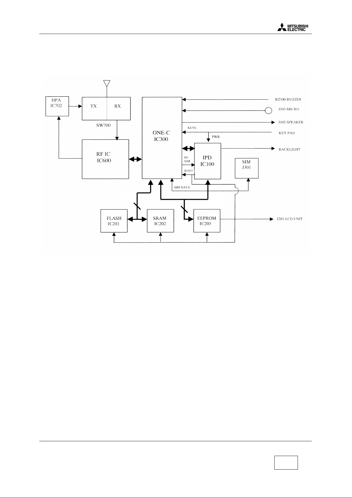
1 Block Diagram
1.1 Schematic
Parallele bus
1.2 Description of Block Diagram.
1.2.1 IC300 One-C (VWS22100).
IC300 includes in one same chipset Base Band part, DSP, CPU, A/D, D/A converters, TDMA
framecounters, a TX GMSK modulator, a TX power ramping circuit, RX filters. IC300 carries out the
management of the battery charging, and of the audio part. It interfaces with the radio frequency
part.
1.2.2 IC100 IPD (Rohm BH6070KU).
IC100 provides the different powers supplies to RFBB board : 2.8RTC, PSTCXO, 2.8VANA, PSSYN,
2.8VAUD, VBAT, 3.6VB, 2.8VD, 5VSIM. The management of the battery charging is carried out by
internal circuit of IC100.
1.2.3 IC600 RF-IC (Hitachi HD155121FEB).
Transceiver IC for E-GSM and DCS Dual Band cellular systems.
Mitsubishi Electric Telecom Europe SA Version E
ZA le Piquet, 35370 Etrelles Date: 04/00
Phone: +33 2 99 75 71 00
Fax: + 33 2 99 75 71 47
3/29
Page 5
Level 3 Service Manual
GALAXY ASTRAL GEO GEO WAP
1.2.4 Memory system.
Location Type Data Size
Galaxy Astral Geo
IC201 Flash ROM CPUprogram code 1 MB 2MB
IC202 RAM Data for CPU work 128 kB 128 kB
IC203 EEPROM Data user, RF adj. 64 kB 128 kB
1.2.5 System Clock.
The system clock for the telephone is 13 MHz TCXO, generated by X600. It is processed in IC300 to
provide serial clock for LCD, EEPROM, and IC100. The clock is buffered in IC300 One-C, and then
fed to IC100 IPD as “ CPU CLK ” . It is available on pin 56 of IC100.
During Stand-By mode, the system clock is not managed from X600 TCXO but from X300 ( “ slow
clock ” at 32.768 kHz).
Size
Geo WAP
Version E Mitsubishi Electric Telecom Europe SA
Date: 04/00 ZA le Piquet 35370 Etrelles
4/29
Phone: +33 2 99 75 71 00
Fax: + 33 2 99 75 71 47
Page 6
Level 3 Service Manual
SPI interface
CHGERR
GALAXY ASTRAL GEO GEO WAP
2. Battery management.
2.1 Block Diagram.
EXPS:
AC/DC
CLA
DTC
HF kit
thermistor
NIMH
900mAh
TH
charger
I charge
+
IPD
5,8V nominal
Green led
Red led
3,8V nominal
BLEV
BYPASS
IPD
regulators
GPIO9
AUX_IN0
regulators
Base Band
One-C
GPIO10
RADIO
2.2 Description.
The battery is NiMH 900mAh, 3.8 V nominal for Galaxy, Astral and Geo
External power supply for charging (EXPS) comes from the DC jack at the bottom side of the mobile
(AC/DC, CLA, DTC or H/F Kit). This power supply is 5.8 V nominal. Battery presence and battery
type information are accessible in CHGM IPD register. If a Li-ion battery is detect, the software
considers that the battery is absent.
The battery temperature information (TH) is given by thresholds in IPD CHGM register. This
information are used only for charge control.
The battery level information is accessible in an A/D converter in One-C. It is also available in CHGM
IPD register , these information are given by range only for range control.
External power supply (EXPS) presence information are accessible in CHGD IPD register. As
described in the drawing above, the power supply for Base Band (IC300) comes from EXPS when it is
present because EXPS level (5.8 V) is always greater than battery voltage. On the contrary, power
supply for radio always comes from the battery.
The serial diode between battery and One-C (IC300) can be bypassed by software to reduce voltage
headroom. Bypass is Activated when battery is less than 3.45 V.
Mitsubishi Electric Telecom Europe SA Version E
ZA le Piquet, 35370 Etrelles Date: 04/00
Phone: +33 2 99 75 71 00
Fax: + 33 2 99 75 71 47
5/29
Page 7
Level 3 Service Manual
GALAXY ASTRAL GEO GEO WAP
Version E Mitsubishi Electric Telecom Europe SA
Date: 04/00 ZA le Piquet 35370 Etrelles
6/29
Phone: +33 2 99 75 71 00
Fax: + 33 2 99 75 71 47
Page 8
Level 3 Service Manual
GALAXY ASTRAL GEO GEO WAP
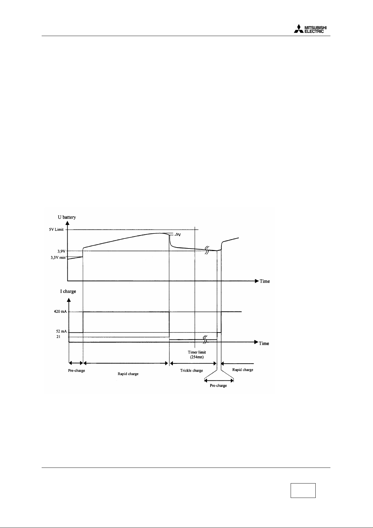
2.3 Charging process.
Charging process follows these successive phases :
Pre charge :This phase is mandatory before the rapid charge to verify that battery operation is
normal (normal battery voltage and temperature). Charge current during this phase is 52 mA. If the
battery voltage is higher than 3.3 Volts, the S/W launch IPD charger in rapid charge except if the
temperature is not between 0°C and 55°C.
2) Rapid charge : Charge current during this phase is 420mA. If battery temperature becomes
abnormal IPD charger start at low current charge (21 mA), while temperature comes back normal
(between 0°C and +55°C) during 15 mn. Full charge detection ends Rapid charge. Full charge is
detected by S/W when charge current decreases under 50 mA (full charge convergence current).
3) Trickle mode :This phase is necessary to complete the charge and to avoid battery auto
discharge. Charge current during this phase is 21 mA. Trickle charge is automatically stopped after 24
hours duration.
Mitsubishi Electric Telecom Europe SA Version E
ZA le Piquet, 35370 Etrelles Date: 04/00
Phone: +33 2 99 75 71 00
Fax: + 33 2 99 75 71 47
7/29
Page 9
Level 3 Service Manual
100%
0%
GALAXY ASTRAL GEO GEO WAP
2.4 Main characteristics.
The phone transmits only if the battery is attached to it, in any configuration of power supply. When
the phone is connected to H/F adapter, DTC, AC/DC, or CLA, the battery charging circuit operates.
Battery voltage (+3.8 V) is applied via D118 or from TESTPS ( J103 pin1 ) through D124 when using
Hand Free.
The main power supply is fed to the phone either from the attached battery via the connector J101, or
from accessories :
• H/F adapter,
• Desk Top Charger DTC,
• AC/DC adapter and CLA via the external connector J103.
R120 and R121 give an internal voltage reference. If the battery voltage VBAT falls down, then
BYPASS shorts out the diode D118 through TR103 to reduce voltage drop.
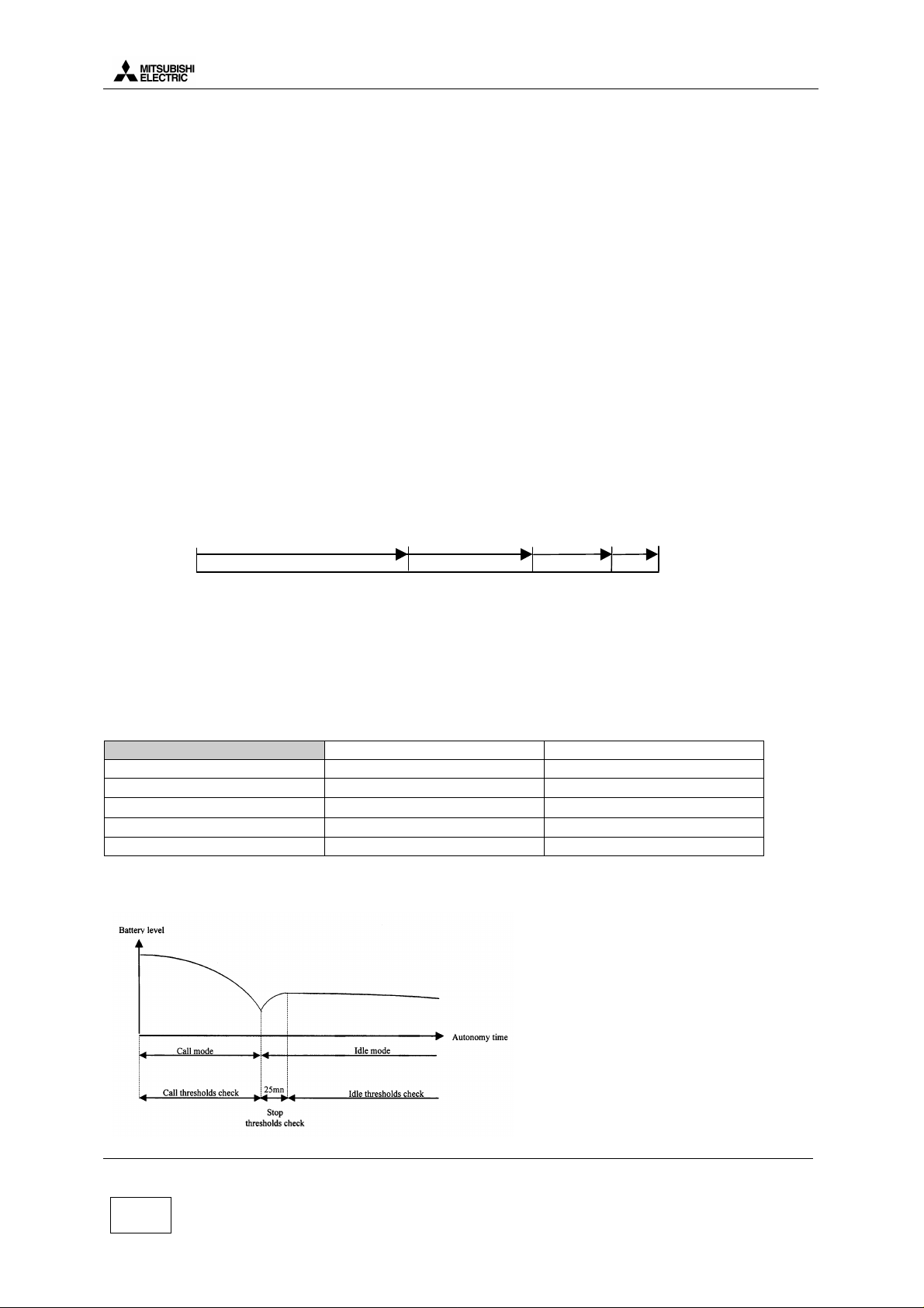
2.5 Autonomy Control.
The battery energy is displayed on the LCD by a 3 bars “battery icon” . Voltage thresholds for each
bars are calculated to have this autonomy time share out:
1 bar
97%
0 bar
40%
3 bars
A 3 times 33% time shares out is not possible because of the very stable battery level between 20%
to 50% autonomy time. In addition with these bars, a ” low battery alarm” is displayed between ”1
bar” and the mobile off.
All these thresholds are programmed in EEprom by the factory and given in following thresholds
table.
Idle Mode Call Mode
Initial thresholds Battery level Battery level
3 bars → 2 bars
2 bars → 1 bars
1 bar → low battery alarm
Power off 3.46V 3.30V
Thresholds are different according to the mode, Idle mode or Call mode. Idle mode threshold are
checked by software 25 min after the end of the call.
3.86V 3.77V
3.71V 3.60V
3.57V 3.40V
2 bars
80%
When battery voltage is less than the threshold given in the table above, BAT_EMPTY is true.
Version E Mitsubishi Electric Telecom Europe SA
Date: 04/00 ZA le Piquet 35370 Etrelles
8/29
Phone: +33 2 99 75 71 00
Fax: + 33 2 99 75 71 47
Page 10
Level 3 Service Manual
GALAXY ASTRAL GEO GEO WAP
The mobile is then powered off by Power Control.
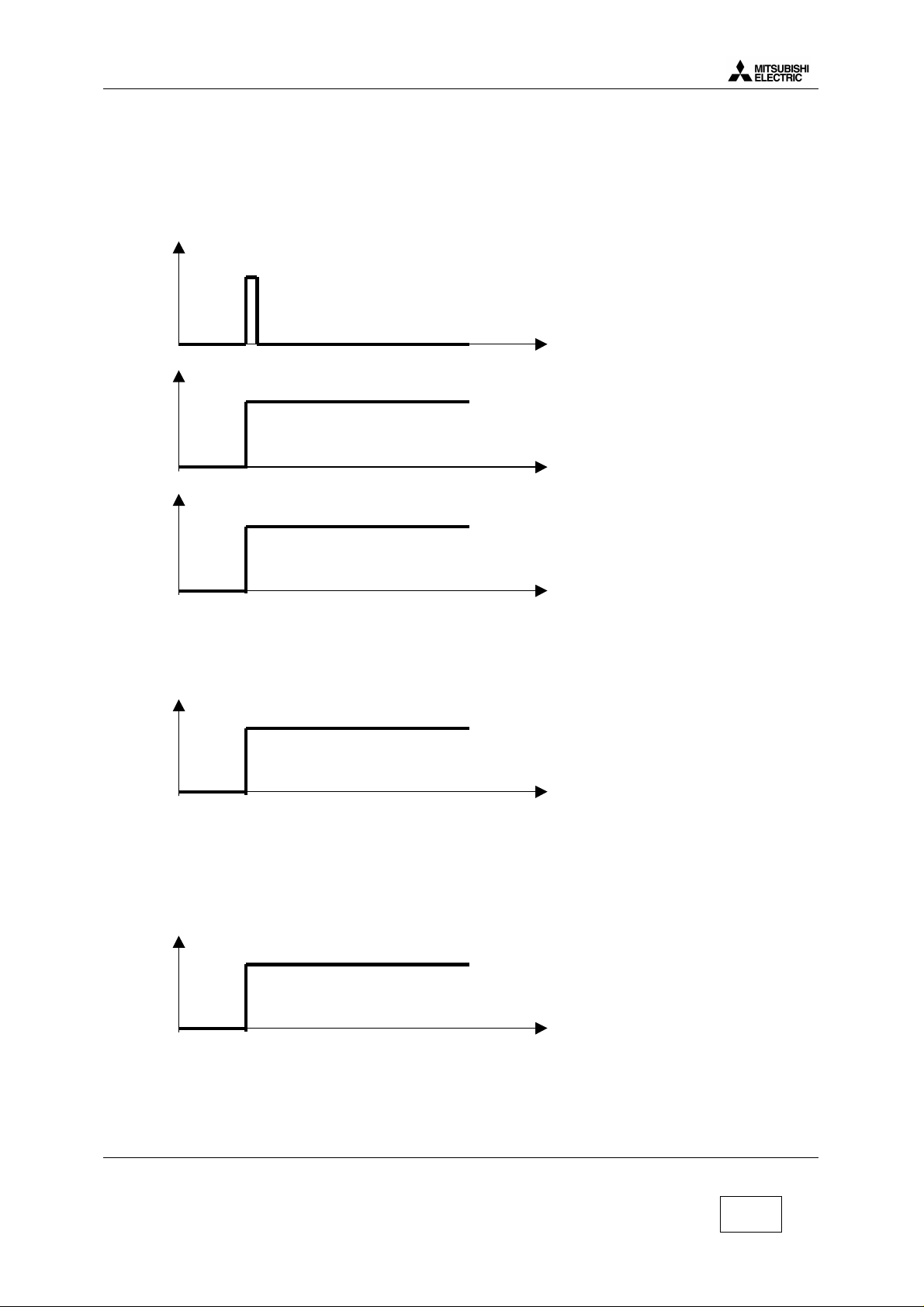
2.6 Power on.
To switch on the mobile, three possibilities exist :
With a battery :
PWRKEY
t
BBPWR
IC300 pin L8
t
MUPSU
IC100 pin49
t
During these mode TESTPS and EXPS = low voltage level.
A high voltage level on MUPSU implies regulators REG 4, REG 5, REG 6, REG 7 are active.
- With Interface and I/O connector (Testmode M.T.S) :
TESTPS
to t
t0= connexion I/O cable
When you connect I/O connector, MUPSU and BBPWR signals have the same waveform at
TESTPS.
During this condition PWRKEY and EXPS = low voltage level.
- With AC/DC Charger, Cigar Light Adapter and DeskTop Charger.
EXPS
t0
t0= connection by external power.
When an accessory is connect, MUPSU and BBPWR signals have the same waveform that TESTPS.
During this condition PWRKEY and TESTPS = low voltage level
Mitsubishi Electric Telecom Europe SA Version E
ZA le Piquet, 35370 Etrelles Date: 04/00
Phone: +33 2 99 75 71 00
Fax: + 33 2 99 75 71 47
9/29
Page 11

2.7 Power off.
PWRKEY
t
3s
BBPWR
MUPSU
t
5s
2.8 Real Time Clock (Geo and Geo WAP)
Level 3 Service Manual
GALAXY ASTRAL GEO GEO WAP
Real time clock lives in ONE C (IC300) and energy is provided :
• By IC100 (pin 48) via D105, when the main battery is connected.
• By BT100 (back up battery) via D105, when the main battery is empty or not connected
IC300
VDD_RTCVCC
D105 C305 IC100
REG80
BT100
Version E Mitsubishi Electric Telecom Europe SA
Date: 04/00 ZA le Piquet 35370 Etrelles
10/29
Phone: +33 2 99 75 71 00
Fax: + 33 2 99 75 71 47
Page 12

Level 3 Service Manual
915Mhz
1575
GALAXY ASTRAL GEO GEO WAP
3. RF Section.
3.1 Frequency range.
3.1.1 E-GSM Frequency :
124 Channels. 1≤ N ≤124 and 48 Channels. 975 ≤ N ≤1023
Receive frequency : 925.2~959.8 MHz
RX frequency = 935.0+0.2*N for (1≤ N ≤124) and 935.0+0.2*(N-1024) for ( 975 ≤ N ≤1023)
Transmit frequency : 880.2~914.8 MHz
TX frequency = 890.0+0.2*N for (1≤ N ≤124) and 890.0+0.2*N for ( 975≤ N ≤1023)
E-GSM BAND
880 TX
35Mhz 35Mhz
45Mhz
RF-PLL E-GSM BAND
1150
TX/RX
35Mhz
1185Mhz
925 RX 960 Mhz
RX 1st IF is 225MHz
RX 2nd IF is 45MHz
3.1.2 DCS Frequency :
374 Channels. 512≤ N ≤885
Receive frequency : 1805.2~1879.2 MHz
RX frequency = 1805.2+0.2*(N-512).
Transmit frequency 1710.2~1784.8 MHz
TX frequency = 1710.2+0.2*(N-512).
DCS BAND
1710 TX
1785Mhz
1805 RX 1880Mhz
75Mhz 75Mhz
95Mhz
RF-PLL DCS BAND
TX
75Mhz
1650Mhz
1580 1655MhzRX
75Mhz
RX 1st IF is 225MHz
RX 2nd IF is 45MHz
Mitsubishi Electric Telecom Europe SA Version E
ZA le Piquet, 35370 Etrelles Date: 04/00
Phone: +33 2 99 75 71 00
Fax: + 33 2 99 75 71 47
11/29
Page 13

3.2 Synthetiser Circuit Description.
Level 3 Service Manual
GALAXY ASTRAL GEO GEO WAP
Switching between GSM and DCS band is performed by programming the LMX2331LTM (IC601) with
the serial data in BBE from CPU.
The serial data lines are connected directly to the serial input pin of the PLL IC (IC 601), and are used
to program the 2 PLLs of the IC.
The LMX2331LTM has two PLLs : one is variable frequency (RF PLL), and the other is fixed
frequency (IF PLL).
RF-PLL : variable frequency PLL for RX and TX for both GSM and DCS bands.
Oscillation Frequency Ranges : - For E-GSM Band / 1150 - 1185MHz
- For DCS TX / 1575 - 1650MHz
- For DCS RX / 1580 - 1655MHz
IF-PLL : Fixed frequency 540 MHz for IF of TX and RX for both E-GSM and DCS bands.
The signal BANDSW controls the E-GSM/DCS Band switching.
BANDSW RF BAND
0 E-GSM
1 DCS
In order to achieve the channel spacing, the reference frequency is set to 200 kHz.
Version E Mitsubishi Electric Telecom Europe SA
Date: 04/00 ZA le Piquet 35370 Etrelles
12/29
Phone: +33 2 99 75 71 00
Fax: + 33 2 99 75 71 47
Page 14

Level 3 Service Manual
GALAXY ASTRAL GEO GEO WAP
3.3 RF Block Diagram.
Mitsubishi Electric Telecom Europe SA Version E
ZA le Piquet, 35370 Etrelles Date: 04/00
Phone: +33 2 99 75 71 00
Fax: + 33 2 99 75 71 47
13/29
Page 15

3.4 Reception
3.4.1 Reception Block Diagram.
Level 3 Service Manual
GALAXY ASTRAL GEO GEO WAP
3.4.2 Description of Reception Block Diagram
E-GSM band (925-960MHz).
Incoming RF signal from aerial is filtered and switched to the RX GSM path through SW700 . The
signal is filtered by FL504 , before to be amplified by TR504 , and is further filtered by FL503. Then,
the signal input to RF-IC (IC600) in a first mixer stage. The RF signal (925-960 MHz) is mixed with
the RF-PLL Frequency (1150-1185 MHz) coming from IC601 (PLL) via IC602 (RF-VCO). For the
channel 1, the output signal of the mixer is 225 MHz (1150 MHz-925 MHz =225 MHz), and is filtered
by FL500.
DSC band (1805-1880MHz).
Incoming RF signal from aerial is filtered and is switched to the RX DCS path through SW700 . The
signal is filtered by FL501 , before to be amplified by TR503 , and is further filtered by FL502. Then,
the signal input to RF-IC (IC600) in a first mixer stage. The RF signal (1805-1880 MHz) is mixed with
the RF-PLL Frequency (1580-1655 MHz) coming from IC601 (PLL) via IC602 (RF-VCO). For the
channel 1, the output signal of the mixer is 225 MHz (1805 MHz-1575 MHz =225 MHz), and is
filtered by FL500.
For the E-GSM and DCS bands.
The first intermediate frequency is 225 MHz. Then, these frequency is filtered by FL 500 before input
to the second mixer stage. The first IF (225 MHz) is mixed with the 270 MHz (Fixed Frequency PLL
540 MHz/2=270 MHz), to a second IF : 45 MHz. The 2nd IF is demodulated to Base Band (IC300)
I/Q phase demodulated signals. RF-IC (IC600) provides automatic gain control.
IC600 includes a quadrature demodulator using a divide by four technique for 90° phase splitter. The
2nd IF signal (45 MHz) is demodulated to I, Q balanced signals for BBE.
Version E Mitsubishi Electric Telecom Europe SA
Date: 04/00 ZA le Piquet 35370 Etrelles
14/29
Phone: +33 2 99 75 71 00
Fax: + 33 2 99 75 71 47
Page 16

Level 3 Service Manual
GALAXY ASTRAL GEO GEO WAP
3.5 Transmission.
3.5.1 Transmission Block Diagram.
3.5.2 Description of Transmission Block Diagram.
The direct and phase shifted signals are then fed to I and Q modulators inside the IC600. I and Q data
components are fed into the IC600. The output from the two modulators is summed and fed out of
pin 11. The GMSK signal leaves the modulator of IC600, and is amplified also inside IC600.
E-GSM Band (880-915MHz).
A phase locked loop is created around the TXVCO IC700. The output is fed into IC600 and converted
to 270 MHz (135MHz on DCS) by mixing with RFVCO at 1150-1185 MHz (1575 – 1650 MHz DCS).
This 270 MHz signal is compared with the 270MHz signal from the modulators, and the error signal is
used to control the TXVCO. Note that the error signal on TP700 will have a DC component to control
frequency, and an AC component at approx 270 kHz to control phase changes. Then the signal is
filtered, amplified by TR702, and further filtered before to input to the power amplifier (IC702).From
the PA, the output goes through coupler Z701, is switched to the TX path and is filtered by SW700.
The signal then goes up to the antenna.
DCS Band (1710-1785MHz).
A phase locked loop is created around the TXVCO IC700. The output is fed into IC600 and converted
to 135 MHz (270 MHz on GSM) by mixing with RFVCO at 1575 – 1650 MHz. This 135 MHz signal is
compared with the 135MHz signal from the modulators, and the error signal is used to control the
TXVCO. Note that the error signal on TP700 will have a DC component to control frequency, and an
AC component at approx 270 kHz to control phase changes. Then the signal is filtered, amplified by
TR712, and further filtered before to input to the power amplifier (IC702).From the PA, the output
goes through coupler Z 700, is switched to the TX path and is filtered by SW700. The signal then
goes up to the antenna.
Mitsubishi Electric Telecom Europe SA Version E
ZA le Piquet, 35370 Etrelles Date: 04/00
Phone: +33 2 99 75 71 00
Fax: + 33 2 99 75 71 47
15/29
Page 17

3.5.3 Power Control.
Level 3 Service Manual
GALAXY ASTRAL GEO GEO WAP
APCCNT is the reference waveform voltage for a TX burst (provided by IC300).
TX1SW : This control signal is used to switch on/off the preamplifiers. ( TR702 and TR712 )
H.Level : Pre Amp is active.
L.Level : Pre Amp is not active.
TX3SW :This control signal is used to switch on/off the operational amplifier of the APC Loop (IC710).
H. Level : Detecting Circuit and comparison Error AMP is active.
L. Level : Detecting Circuit and comparison Error AMP is not active.
RF signal is rectified by voltage doubler Schottky barrier diodes D700. This level is compared with
APCCNT. The result of the comparison is used to vary the gain of the HPA IC702.
The APCCNT signal input from the base band circuit (IC300) contains the burst shaping information
and the power level to be set among the 15 power levels defined by the GSM, or the 16 power levels
defined by the DCS specifications. It controls the output power level by a feed-back loop (Automatic
Power Control ).
E-GSM DCS
PCL 5 → +33 dBm PCL 0 → +30 dBm
PCL 19 → +5 dBm PCL15 → +0 dBm
Version E Mitsubishi Electric Telecom Europe SA
Date: 04/00 ZA le Piquet 35370 Etrelles
16/29
Phone: +33 2 99 75 71 00
Fax: + 33 2 99 75 71 47
Page 18

Level 3 Service Manual
GALAXY ASTRAL GEO GEO WAP
4. Speech coder.
Audio is sampled at 8 kHz rate, and divided into 20 ms blocks of 160 samples per block. Each 20 ms
block is characterised by 260 bits i.e. 13 kbits/sec. The resulting signal is processed by a regular
pulse excitation - long term predictor (RPE - LTP) codec. This yields a digital representation of vocal
chord vibrations, together with the filter characteristics which must be applied to them to make voice
sounds.
The most significant 182 bits will go through error correction and become 378 bits. The less critical
group of 78 bits will not go through error correction and will just be summed with the 378 bits which
will yield 456 bits.
Voice
SPEECH CODER
error correction
block coding
378 bits
378 bits
8 blocks of 57 bits
57 57 5757 575757 57
5757 5757
time slot time slot
160 voice samples = 20 ms
260 bits (20 ms)182 bits 78 bits
78 bits
456 bits
next speech block
5757 57
These 456 bits are then separated in 8 blocks of 57 data bits.
These blocks are interleaved with adjacent blocks to guard against burst errors and broken up into
blocks of 114 bits for transmission. This block of 114 bits are the data bits of the timeslot.
Timing data is added, and the resulting bit stream is fed to the Gaussian Minimum Shift Keying
(GMSK) modulator, where the bits are taken two at a time and used to smoothly change the phase of
an RF carrier according to bit combination.
4.1 Full rate / Half rate / Enhanced full rate.
The data rate of 13 kbit/sec ( full rate ) is considerably lower than for direct speech digitising as in
PCM. Now more advanced voice coders cut this to 5.6 kbit/sec ( half rate coding ).
The enhanced full rate, is just a full rate with a different speech coder which improves the
transmission quality.
Mitsubishi Electric Telecom Europe SA Version E
ZA le Piquet, 35370 Etrelles Date: 04/00
Phone: +33 2 99 75 71 00
Fax: + 33 2 99 75 71 47
17/29
Page 19

Level 3 Service Manual
GALAXY ASTRAL GEO GEO WAP
Version E Mitsubishi Electric Telecom Europe SA
Date: 04/00 ZA le Piquet 35370 Etrelles
18/29
Phone: +33 2 99 75 71 00
Fax: + 33 2 99 75 71 47
Page 20

Level 3 Service Manual
GALAXY ASTRAL GEO GEO WAP
5. Analogue Audio.
The audio part is managed by the One-C circuit (IC300).
5.1 Buzzer.
Diagram : 2.8VD
IC300 (One C)
Buzzer
alerter
F4 TR350
5.2 Speaker (RX audio).
Diagram :
IC300 (One C)
PW01P
PW01N
PW02P
PW02N
5.3 Micro (TX audio).
Diagram :
IC300 (One C)
VX1P
VX1N
MICREFP
MICREFN
internal
receiver
Headset connector J300
Mechanical switch
headset
receiver
hand free
receiver
I/O connector J103 (pin 3 & 14)
Internal micro
I/O connector J103 (pin 17 & 18)
Headset connector J300 (pin 1 & 2)
VXI2P
VXI2N
Headset micro
I/O connector J103 (pin 2 & 14)
Hand free micro
Mitsubishi Electric Telecom Europe SA Version E
ZA le Piquet, 35370 Etrelles Date: 04/00
Phone: +33 2 99 75 71 00
Fax: + 33 2 99 75 71 47
19/29
Page 21

Level 3 Service Manual
GALAXY ASTRAL GEO GEO WAP
When Handfree Kit is used there is a high level on HFDETL (J103 pin 5).
6. Testmode Software.
For M4 family test mode is not directly possible from the mobile indeed relevant software is available
on PC only.
• Basic test mode functions (delete data user, print labels, download of settings) are available in
MSTools software (see level 2 service manual),
• Download of mobile software is available with IPLTrium software (see level 2 service manual).
• More advanced testmode functions to test the mobile are available in MTS software. This
software can be used only with a runtime engine TEST STAND.
When making measurement on the board itself, it is possible to power the board from the M4
interface box.
6.1 Equipment installation
RADIOCOMMUNICATION TESTER
Mobile without battery
GPIB Connection for Autotest only
(not requested for test mode)
External supply
4.5V
RF Cable NN 50 OHMS 0.8
(FT7Y005610)
Serial Cable
FT7Y002110
NSMA ADAPTATOR FEMALE
(FT7Y010010)
M4RF CABLE SMA L500
(FT7Y006110)
M4 Interface Box
FT7Y009410
M4 Interface Cable
FT7Y007010
The test mode is used to control or adjust mobile parameters.
You must have the following requirements :
• Radio-communication tester
• M4 RF cable SMA L500
• M4 Interface cable
• M4 Interface Box
• Serial Cable
• Computer under Windows 95 (PII 350 MHz 64 Mb recommended)
If you want to use autotest function which is included in MTS, then your Radio-communication tester
must be a CMD55 (with firmware 3.6 and GPIB interface) and your computer must have GPIB
interface. The result of autotest (measurement values) is displayed as HTML file.
Version E Mitsubishi Electric Telecom Europe SA
Date: 04/00 ZA le Piquet 35370 Etrelles
Phone: +33 2 99 75 71 00
20/29
Fax: + 33 2 99 75 71 47
Page 22

Level 3 Service Manual
GALAXY ASTRAL GEO GEO WAP
6.2 Software (MTS) installation
This part describes how to install the different components of MTS depending of the functions of MTS
you want to use.
6.2.1 Simple Setup :
If you want to have only the test mode functions (control and adjust RF parameters), follow this
procedure:
• Launch Setup.exe on MTS CD ROM root.
• Select the Custom Setup Type in Setup Type selection window and click on
• Select the component as follow :
a MTS Application
a TestStand Engine
GPIB Software
NI-VISA Software
Internet Explorer
Then continue the setup program until Reboot information window and reboot.
Next >
MTS after sale service is now available in ÿ Start, Program, MTS After Sale Service
6.2.2 Complete Setup :
If you want to have all the function of MTS (control and adjust the RF parameters, execute and
parameter the autotests), follow this procedure :
• Launch Setup.exe on MTS CD ROM root.
• Select the Typical Setup Type in Setup Type selection window and click on
• Then continue the setup program until Reboot information window and reboot.
MTS after sale service is now available in ÿ Start, Program, MTS After Sale Service
Before you launch an autotest, you must unvalid the step : 4301 DIO initialisation
For that you have to turn the Execution mode switch on run selected step in the autotest page.
Next >
Mitsubishi Electric Telecom Europe SA Version E
ZA le Piquet, 35370 Etrelles Date: 04/00
Phone: +33 2 99 75 71 00
Fax: + 33 2 99 75 71 47
21/29
Page 23

GALAXY ASTRAL GEO GEO WAP
battery)
6.3 Software (MTS) description
When you launch MTS from start menu you the main screen is displayed :
Level 3 Service Manual
Identificatio
n
(click here to display
PCA number, IMEI,
Hardware version,
Software version,
6.3.1 MMI Testmode interface : description of functions
Testmode
(click here to enter in…)
Autotests
M4
(click here to execute
an…)
Calibration
(click here to adjust the
RF losses parameters)
Exit
(click here to exit, the
WINDOWS © commands
are not available)
TestMode
(click here to enter and
stop test mode
Mobile
(click here to know the
software version )
RF
(click here to control and
adjust TX, RX, TCXO)
Quit
(click here to exit, the
WINDOWS © commands
are not available)
Battery
(click here to measure
the voltage of the
MMI
(click here to activate
backlight, LCD, vibrator
and RTC)
RF
Parameters
(to activate TX or RX, to
change the band, the
channel, the PCL… )
Audio
(click here to activate the
buzzer and to select
audio path)
Version E Mitsubishi Electric Telecom Europe SA
Date: 04/00 ZA le Piquet 35370 Etrelles
Phone: +33 2 99 75 71 00
22/29
Fax: + 33 2 99 75 71 47
Page 24

Level 3 Service Manual
GALAXY ASTRAL GEO GEO WAP
How to enter in test mode ?
The mobile can be turned in test mode from two different ways :
• Using test mode code (hold the * and enter 5472) and PC cable S1&D (FK8L010910)
or
• Using the M4 interface box (FT7Y009410) and M4 interface cable (FT7Y007010)
When the mobile displays :
Mitsubishi
M4 Testmode
You can enter in Testmode, for that, choose Enter in Testmode menu as follow.
Information
window
When the communication is established between mobile and computer the information window
displays :
Start Testmode Passed
Mitsubishi Electric Telecom Europe SA Version E
ZA le Piquet, 35370 Etrelles Date: 04/00
Phone: +33 2 99 75 71 00
Fax: + 33 2 99 75 71 47
23/29
Page 25

Level 3 Service Manual
GALAXY ASTRAL GEO GEO WAP
Power adjustment :
To enter in Power adjustments, choose RF menu, Adjustment, Adjustment TX, Adjustment burst
as follow :
Then, the Ramping parameters Window is displayed as follow :
Version E Mitsubishi Electric Telecom Europe SA
Date: 04/00 ZA le Piquet 35370 Etrelles
24/29
Phone: +33 2 99 75 71 00
Fax: + 33 2 99 75 71 47
Page 26

Level 3 Service Manual
GALAXY ASTRAL GEO GEO WAP
To adjust RSSI (if RX level is not good, for example), you have to process to different steps :
RX SPLIT and RSSI ADJUSTMENT
• For RX Split we choose :
RF menu, Adjustment, Adjustment RX, Split RX as follow :
Then we fix RX split at the right value :
For the E-GSM band the number of sub-bands is 1(no split)
For the DCS band the number of sub-bands is 3
We split the DCS band as follow : L range : 512 to 539
M range : 540 to 850
H range : 851 to 885
The RX split window should be as follow :
Now you can adjust RSSI for each sub-band.
Mitsubishi Electric Telecom Europe SA Version E
ZA le Piquet, 35370 Etrelles Date: 04/00
Phone: +33 2 99 75 71 00
Fax: + 33 2 99 75 71 47
25/29
Page 27

GALAXY ASTRAL GEO GEO WAP
• For RSSI ADJUSTMENT, we choose :
RF menu, Adjustment, Adjustment RX, Adjustment RSSI (rapport AGC).
Then we get the RSSI window :
Level 3 Service Manual
To adjust RSSI ,we input a GMSK modulated signal (67.7 kHz shifted) at level and channel as follow :
Step Channel Level (dBm)
1 37 -82.5
2 37 -31.5
3 525 -82.5
4 525 -31.5
5 695 -82.5
6 695 -31.5
7 868 -82.5
8 868 -31.5
If the RX level measurement is not good in E-GSM we adjust only the E-GSM band (step 1 and 2)
If the RX level measurement is not good in DCS we adjust only the DCS band (step 3 to 8).
Version E Mitsubishi Electric Telecom Europe SA
Date: 04/00 ZA le Piquet 35370 Etrelles
26/29
Phone: +33 2 99 75 71 00
Fax: + 33 2 99 75 71 47
Page 28

Level 3 Service Manual
GALAXY ASTRAL GEO GEO WAP
7. Basic Adjustment.
7.1 Power Adjustment.
For the M4 Family Mobiles, Mitsubishi uses only MELCO HPA (IC701). Each mobile is adjusted in the
factory and the TX parameters (Power Control Level values and ramping values) are stored in the
EEPROM (IC202).
About the adjustment value of TX Power, see the following table.
E-GSM DCS
Ch-62
PCL
5
6
7
8
9
10
11
12
13
14
15
16
17
18
19
Example of adjustment value table with MELCO HPA.
E-GSM Table:
Power Level
(dBm)
33 +/-2dB
31 +/-3dB
29 +/-3dB
27 +/-3dB
25 +/-3dB
23 +/-3dB
21 +/-3dB
19 +/-3dB
17 +/-3dB
15 +/-3dB
13 +/-3dB
11 +/-5dB
9 +/-5dB
7 +/-5dB
5 +/-5dB
tolerance Ch-698
E-GSM
Ch-62
PCL
5
6
7
8
9
10
11
12
13
14
15
16
17
18
Power
Level
(dBm)
32.1 567 152 16 16 16 16
30.7 502 152 16 16 16 16
28.7 429 147 16 16 12 19
26.7 373 147 14 16 12 19
24.7 329 142 14 18 12 19
22.8 294 142 14 18 12 19
20.3 262 142 14 18 12 19
18.5 243 142 17 18 12 19
16.6 225 142 16 14 12 19
14.4 210 132 16 14 12 19
12.4 199 132 16 14 12 19
10.1 189 132 15 14 12 19
8 182 132 15 12 12 19
6.1 177 132 13 12 12 19
Pmax
(DEC)
Pmin
(DEC)
Pmin
UP Time
PCL
0
1
2
3
4
5
6
7
8
9
10
11
12
13
14
15
Ramp
UP Time
Power Level
(dBm)
Pmin
DN Time
tolerance
30 +/-2dB
28 +/-3dB
26 +/-3dB
24 +/-3dB
22 +/-3dB
20 +/-3dB
18 +/-3dB
16 +/-3dB
14 +/-3dB
12 +/-4dB
10 +/-4dB
8 +/-4dB
6 +/-4dB
4 +/-4dB
2 +/-5dB
0 +/-5dB
Ramp
DN Time
Mitsubishi Electric Telecom Europe SA Version E
ZA le Piquet, 35370 Etrelles Date: 04/00
Phone: +33 2 99 75 71 00
Fax: + 33 2 99 75 71 47
27/29
Page 29

Level 3 Service Manual
GALAXY ASTRAL GEO GEO WAP
19
DCS Table:
Ch-698
PCL
0
1
2
3
4
5
6
7
8
9
10
11
12
13
14
15
3.8 172 122 11 12 12 19
DCS
Power
Level
(dBm)
29 731 183 18 14 12 20
27.6 647 183 18 14 12 19
25.7 551 183 18 14 12 19
23.8 481 178 18 14 12 19
21.7 414 173 18 14 12 19
19.9 368 173 18 14 12 19
17.9 328 168 18 14 12 19
15.9 296 168 18 14 12 19
13.9 269 168 18 14 12 19
12 251 168 17 14 12 19
10.6 237 108 15 12 12 19
9.3 227 108 15 12 12 19
7.8 218 108 15 12 14 17
5.8 208 108 15 12 14 17
3.6 200 108 13 12 14 17
1.2 194 108 9 12 14 17
Pmax
(DEC)
Pmin
(DEC)
Pmin
UP Time
Ramp
UP Time
Pmin
DN Time
DN Time
Ramp
7.2 RSSI control.
To control RSSI go back to page 24 of the manual.
Set your radiocommunication tester at a given reference and check RSSI :
REF Gene RSSI
-83.5 dBm 27 +/- 4
-60.5 dBm 50 +/- 4
8. Software Version .
The software version is coded with 8 digits, evolving in the following order : 0, 1, 2, ...,9, A, B, ...,Z, a,
b,...,z.
F H S V E Vf Ef Vc
F : Family ex : 1 M3, 2 M4, ….
H : Hardware ex : 1 GALAXY, 5 GEO, 3 ARIA, e GEO WAP, j COSMO, c GEO GPRS….
S : Software ex :
V : Version ex :
E, Vf, Ef, Vc are Mitsubishi Code.
Version E Mitsubishi Electric Telecom Europe SA
Date: 04/00 ZA le Piquet 35370 Etrelles
28/29
Phone: +33 2 99 75 71 00
Fax: + 33 2 99 75 71 47
Page 30

Level 3 Service Manual
GALAXY ASTRAL GEO GEO WAP
9. Trouble Shooting help guide
Defects observed Mesure/Investigation Test
report
CHARGING PROBLEM
Consumption in charge: begin at 125 mA, red led light up, displayed "Charging", increase between 520 and
580 mA with backlight switch on and decrease between 450 to 500 mA
Charging problem 60 < Ich < 100 mA + no charging display-Vbat=4,8 V
instead of 1,04v with charge cable, without battery
Charging problem 70 < lch < 76 mA, Vth=2.5 V (j101 pin2) IC100
No charging visual check : connector J103 broken xg003 J103
Charging no good Displayed Charging, consumption at 72mA increase to
155 mA
Charging no good Displayed Charging, consumption at 123mA increase to 175
mA and decrease to 80mA
Charging no good Displayed Charging, consumption at 850mA (Vth=1.1 V
instead of 2.5 V)
Charging no good Displayed Low Battery, Consumption at 180mA R120, R121, TR104
Charging no good Displayed "TestMode", Consumption at 25mA D125, TR106
Charging no good Displayed Full Battery after few secondes R121, TR106
Charging no good 3.6VB=3.7 V instead of 5 V in charging xg013 D117 (resoldering
AUDIO PROBLEM
Noisy audio Noisy audio during DCS real call but audio good with
DCS tester with speaker no good
Noisy audio Noisy audio during DCS real call but audio good with
DCS tester with speaker good
Low audio HSDET voltage no good(not equal to 0v) and J300
already changed
Low speaker visual check : C333 missing (0.1 µF) xg010 C333
Low buzzer check audio path R327, R328
No buzzer check audio path TR350, D300,IC300
No speaker check audio path xg005 IC300
No speaker visual check on audio path xg023 J300 (resoldering
LOCATION UPDATE
RX level DCS no good check the RX DCS path : 15 dbm loses instead of 2 in the
SW700
No Service DCS Swtiching + 400 kHz no good xg008 adjust each PCL in
No Service EGSM check the RX GSM path : LNA output level at -75 instead
of -27
No Service EGSM Check the RX path (command on SW700 pin4 no good) xg017 SW700
No Service EGSM & DCS TX good in testmode (TX I/Q and RF) + RSSI good in test
mode (RX I/Q and level)
xg001 IC100
xg002 IC300
xg022 IC300
xg024 IC300(L3)
xg006 SW700
xg009 TR504
xg014 IC600
Component no good
correctives action
checks TR106,
TR107, R128, R129
check the power
BLEV
TR106, TR103,D118
only)
only)
DCS band
Mitsubishi Electric Telecom Europe SA Version E
ZA le Piquet, 35370 Etrelles Date: 04/00
Phone: +33 2 99 75 71 00
Fax: + 33 2 99 75 71 47
29/29
Page 31

Level 3 Service Manual
GALAXY ASTRAL GEO GEO WAP
No Service EGSM & DCS check TP700, in GSM Vpp=1.7 V,
in DCS Vpp=1.3 V in TX
Defects observed Mesure/Investigation Test
report
LOCATION UPDATE
No Service EGSM & DCS TX good in testmode (TX I/Q and RF) + RSSI good in test
mode (RX I/Q and level) + IC 600 replaced
No Service EGSM & DCS TCXO frequency no good and impossible to adjust with
TCXO adj val in testmode
No Service EGSM & DCS TX no good in testmode, consumption > 300 mA, IC701
hot
POWER ON PROBLEM
Normal consumption in TestMode : 45mA to 49mA
Power on no good Displayed Test Mode when battery connected on mobile
PS=4,5 V instead 0 V and HFDETL=0 V
No power on Consumption at 15 mA X600
No power on Consumption at 30 mA download or change
No power on check PS TCXO-check L603-PSTCXO=2.8 V xg012 L603 (resoldering
No power on Power on OK with EXPS and TESTPS & visual check :
dirty battery contacts.No power on with batt.
No power on No 13 MHz and Fadj voltage no good, consumption at
60mA
Short autonomy 800 mA < Ich <1.5 A IC701
No power on and no "check battery" displayed when ACDC connected
on mobile without battery
No power on 2.8 VD no good on C114 and 3.6VBat is very low xg026 TR100
No power on Displayed Contact Provider xg011 download SW
No power on Displayed Contact Provider xg011 IC201, IC203
Turn on in Testmode TESTPS voltage is 1 volt instead of 0 (R148 is broken:
value is 68kohms instead of 1 kohms)
DOWNLOAD PROBLEM
No download Short cut on FL100 (2/4 and 3/4 = TXD and RXD).
Displayed Test Mode
MS Protect Initlatch xg004 download SW
MS Protect Initlatch xg004 IC201
SIM PROBLEM
Check SIM DISPLAYED CHECK SIM Change J600
Check SIM DISPLAYED CHECK SIM Change IC300
BIT Error / PHASE Error
Bit Error 5.5% GSM Measurement test no good Change L511
Bit Error 12% Measurement test no good Change FL504
Phase Error DCS Measurement test no good IC700, IC600
xg014 IC300
xg015 X600
xg021 IC701
xg007 R148
xg016 cleaning the battery
xg018 IC300
xg020 download SW
xg025 R148, R147, IC203,
xg019 FL100 (resoldering
IC700
Component no good
correctives action
IC201
only)
contacts
IC201
only)
Version E Mitsubishi Electric Telecom Europe SA
Date: 04/00 ZA le Piquet 35370 Etrelles
30/29
Phone: +33 2 99 75 71 00
Fax: + 33 2 99 75 71 47
Page 32

Level 3 Service Manual
GALAXY ASTRAL GEO GEO WAP
Mitsubishi Electric Telecom Europe SA Version E
ZA le Piquet, 35370 Etrelles Date: 04/00
Phone: +33 2 99 75 71 00
Fax: + 33 2 99 75 71 47
31/29
Page 33

Level 3 Service Manual
GALAXY ASTRAL GEO GEO WAP
Mitsubishi Electric reserves the right to make changes to its products at any time to improve reliability
or manufacturability. Mitsubishi Electric does not assume any liability arising from the use of any
device or circuit described here in, nor does it convey any license under its patent rights or the rights
of others.
Version E Mitsubishi Electric Telecom Europe SA
Date: 04/00 ZA le Piquet 35370 Etrelles
32/29
Phone: +33 2 99 75 71 00
Fax: + 33 2 99 75 71 47
 Loading...