

Page 1

mitsubishi :: Mitsubishi Galant LS V6-3.0L SOHC
(1999)
Page 2

> Relays and Modules > Relays and Modules - Accessories and Optional Equipment > ETACS-ECU <--> [Alarm Module, (Vehicle Antitheft)] > Component Information > Locations
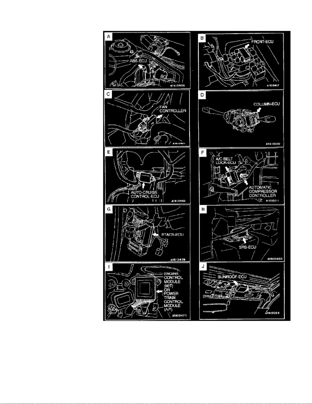
ETACS-ECU: Locations
Control Unit Overall View
Page 3

> Relays and Modules > Relays and Modules - Accessories and Optional Equipment > ETACS-ECU <--> [Alarm Module, (Vehicle Antitheft)] > Component Information >
Locations > Page 7
Galant LS V6-3.0L SOHC (1999)
Page 4

Control Unit Views A - J
NAME SYMBOL
ETACS-ECU G
Page 5

Page 6

> Relays and Modules > Relays and Modules - Accessories and Optional Equipment > ETACS-ECU <--> [Alarm Module, (Vehicle Antitheft)] > Component Information > Diagrams > Diagram Information and Instructions
ETACS-ECU: Diagram Information and Instructions
Connector and Ground Indicators
Page 7

> Relays and Modules > Relays and Modules - Accessories and Optional Equipment > ETACS-ECU <--> [Alarm Module, (Vehicle Antitheft)] > Component Information >
Diagrams > Diagram Information and Instructions > Page 10
Galant LS V6-3.0L SOHC (1999)
Page 8

Page 9

> Relays and Modules > Relays and Modules - Accessories and Optional Equipment > ETACS-ECU <--> [Alarm Module, (Vehicle Antitheft)] > Component Information >
Diagrams > Diagram Information and Instructions > Page 11
Galant LS V6-3.0L SOHC (1999)
Page 10

Connector/Grounding Indications
Definition of Terms
STANDARD VALUE
Indicates the value used as the standard for judging the quality of a part or assembly on inspection or the value to which the part or assembly is correctedand adjusted. It is given by tolerance.
LIMIT
Page 11

> Relays and Modules > Relays and Modules - Accessories and Optional Equipment > ETACS-ECU <--> [Alarm Module, (Vehicle Antitheft)] > Component Information >
Diagrams > Diagram Information and Instructions > Page 12
Galant LS V6-3.0L SOHC (1999)
Shows the standard for judging the quality of a part or assembly on inspection and means the maximum or minimum value within which the part orassembly must be kept functionally or in strength. It is a value established outside the range of standard value.
REFERENCE VALUE
Indicates the adjustment value prior to starting the work (presented in order to facilitate assembly and adjustment procedures, and so they can becompleted in a shorter time).
DANGER, WARNING AND CAUTION
DANGER, WARNING, and CAUTION call special attention to a necessary action or to an action that must be avoided.The difference among DANGER, WARNING, and CAUTION are as follows:
- If a DANGER is not followed, the result is severe bodily harm or even death.
- If a WARNING is not followed, the result could be bodily injury.
Page 12

- If a CAUTION is not followed, the result could be damage to the vehicle, vehicle components or service equipment.
How to Read Circuit Diagrams
Page 13

> Relays and Modules > Relays and Modules - Accessories and Optional Equipment > ETACS-ECU <--> [Alarm Module, (Vehicle Antitheft)] > Component Information >
Diagrams > Diagram Information and Instructions > Page 13
Galant LS V6-3.0L SOHC (1999)
Page 14

The circuit of each system from the fuse (or fusible link) to ground is shown. The power supply is shown at the top and the ground at the bottom tofacilitate understanding of how the current flows.
How to Read Connector/Harness Diagrams
Page 15

> Relays and Modules > Relays and Modules - Accessories and Optional Equipment > ETACS-ECU <--> [Alarm Module, (Vehicle Antitheft)] > Component Information >
Diagrams > Diagram Information and Instructions > Page 14
Galant LS V6-3.0L SOHC (1999)
Page 16

The wiring harness diagrams clearly show the connector locations and harness routings at each site on actual vehicles.
How to Read Splice Locations
Page 17

> Relays and Modules > Relays and Modules - Accessories and Optional Equipment > ETACS-ECU <--> [Alarm Module, (Vehicle Antitheft)] > Component Information >
Diagrams > Diagram Information and Instructions > Page 15
Galant LS V6-3.0L SOHC (1999)
Page 18

"Splice locations" describes splice points of each wiring harness on an actual vehicle.
Key to Wiring Diagrams and Symbol Identification
Page 19

> Relays and Modules > Relays and Modules - Accessories and Optional Equipment > ETACS-ECU <--> [Alarm Module, (Vehicle Antitheft)] > Component Information >
Diagrams > Diagram Information and Instructions > Page 16
Galant LS V6-3.0L SOHC (1999)
Page 20

SYMBOLS (EXCEPT CONNECTOR AND GROUNDING)
Devices appearing in circuit diagrams are indicated by the following symbols.
Special Tool Note
Only MMC special tool part numbers are called out in the repair sections of this manual. Please refer to the special tool cross reference chart, which islocated in the service manual at the beginning of each group, for a cross reference from the MMC special tool number to the special tool number that isavailable in your market.
Wire Color Codes
Wire colors are identified by the following color codes.
Page 21

> Relays and Modules > Relays and Modules - Accessories and Optional Equipment > ETACS-ECU <--> [Alarm Module, (Vehicle Antitheft)] > Component Information >
Diagrams > Diagram Information and Instructions > Page 17
Galant LS V6-3.0L SOHC (1999)
Page 22

If a cable has two colors, the first of the two color code characters indicates the basic color (color of the cable coating) and the second indicates themarking color.
Page 23

Page 24

> Relays and Modules > Relays and Modules - Accessories and Optional Equipment > ETACS-ECU <--> [Alarm Module, (Vehicle Antitheft)] > Component Information > Diagrams > Diagram Information and Instructions >
Page 18
ETACS-ECU: Electrical Diagrams
Key Reminder Tone Alarm
Page 25

> Relays and Modules > Relays and Modules - Accessories and Optional Equipment > ETACS-ECU <--> [Alarm Module, (Vehicle Antitheft)] > Component Information >
Diagrams > Diagram Information and Instructions > Page 19
Galant LS V6-3.0L SOHC (1999)
Part 1 Of 2
Page 26

Part 2 Of 2
Lighting Monitor Tone Alarm
Page 27

> Relays and Modules > Relays and Modules - Accessories and Optional Equipment > ETACS-ECU <--> [Alarm Module, (Vehicle Antitheft)] > Component Information >
Diagrams > Diagram Information and Instructions > Page 20
Galant LS V6-3.0L SOHC (1999)
Page 28

Part 1 Of 2
Page 29

> Relays and Modules > Relays and Modules - Accessories and Optional Equipment > ETACS-ECU <--> [Alarm Module, (Vehicle Antitheft)] > Component Information >
Diagrams > Diagram Information and Instructions > Page 21
Galant LS V6-3.0L SOHC (1999)
Page 30

Part 2 Of 2
Page 31

Page 32

> Relays and Modules > Relays and Modules - Accessories and Optional Equipment > ETACS-ECU <--> [Alarm Module, (Vehicle Antitheft)] > Component Information > Testing and Inspection > Key In Lamp/Buzzer
Diagnosis
ETACS-ECU: Testing and InspectionKey In Lamp/Buzzer Diagnosis
Diagnostic Introduction
INTRODUCTION TO IGNITION SWITCH DIAGNOSIS
ETACS-ECU is mounted in all vehicles. This ETACS-ECU controls the ignition key reminder and ignition key hole illumination light timer. Theignition key reminder tone alarm alerts the driver that the ignition key has not been removed. If any of the following symptoms occur, there is amalfunction:
-
The tone alarm does not stop sounding when the ignition key is turned to the "" position.ON
- The tone alarm does not stop sounding when the ignition key is removed.
-
OFF
The tone alarm does not sound when the ignition key is inserted (turned to the "' position) and the driver's door is opened.The ignition key hole illumination light timer illuminates the ignition switch for certain conditions.If any of the following symptoms occur, there is a malfunction:
-
The ignition key hole illumination light does not go off within .30 seconds
- The ignition key hole illumination light does not illuminate when the driver's door is opened.
-
The ignition key hole illumination light does not go out when the ignition key is turned to the "" position.ON
Diagnostic Strategies
Use these steps to plan your diagnostic strategy. If you follow them carefully, you will be sure that you have exhausted most of the possible ways to findan ignition switch fault.
1. Gather information from the customer.2. Verify that the condition described by the customer exists.3. Find and repair the malfunction by following the SYMPTOM CHART.4. Verify malfunction is eliminated.
1. Ignition Lamp Doesn't Light With Drivers Door Open
Page 33

> Relays and Modules > Relays and Modules - Accessories and Optional Equipment > ETACS-ECU <--> [Alarm Module, (Vehicle Antitheft)] > Component Information >
Testing and Inspection > Key In Lamp/Buzzer Diagnosis > Page 24
Galant LS V6-3.0L SOHC (1999)
Page 34

Page 35

> Relays and Modules > Relays and Modules - Accessories and Optional Equipment > ETACS-ECU <--> [Alarm Module, (Vehicle Antitheft)] > Component Information >
Testing and Inspection > Key In Lamp/Buzzer Diagnosis > Page 25
Galant LS V6-3.0L SOHC (1999)
Page 36

CIRCUIT OPERATION
- The ETACS-ECU monitors the ignition switch by detecting voltage from the ignition switch.
- The ETACS-ECU judges that the driver's door is opened or closed by detecting voltage from the front door switch (LH).
-
ON
When the driver's door is opened (Door switch: ), the ignition key illumination light will illuminate. When the driver's door is closed (Doorswitch: ) the ignition key illumination light will go out within OFF 30 seconds.
TECHNICAL DESCRIPTION (COMMENT)
The cause is probably a malfunction in the key hole illumination light circuit system or input signal from the driver's door switch.
TROUBLESHOOTING HINTS
- Malfunction of the driver's door switch
- Malfunction of the key hole illumination hole illumination light
- Damaged harness wires or connectors
- Malfunction of the ETACS-ECU
DIAGNOSIS
Page 37

> Relays and Modules > Relays and Modules - Accessories and Optional Equipment > ETACS-ECU <--> [Alarm Module, (Vehicle Antitheft)] > Component Information >
Testing and Inspection > Key In Lamp/Buzzer Diagnosis > Page 26
Galant LS V6-3.0L SOHC (1999)
Required Special Tools:MB991502: Scan Tool (MUT-II)MB991529: Diagnostic Trouble Code Check Harness
To prevent damage to scan tool MB991502, make sure that the ignition switch is "" before connecting or disconnecting the scan tool.CAUTION: OFF
STEP 1. Check the input signal from the driver's door switch, using either the scan tool or a voltmeter.
Page 38

Using scan tool MB991502
1. Connect Scan Tool MB991502 to the data link connector.2. Check that the tone alarm of the scan tool sounds when the driver's side door is opened.
If the tone alarm of the scan tool does not sound, the input signal from the driver's door switch is not normal. Go to Step 2.If input signal is normal, go to Step 5.
Using a voltmeter
1. Use special tool MB991529 to connect a voltmeter between ground terminal 4 or 5 and ETACS-ECU terminal 9 of the data link connector.2. If a voltmeter indicator deflects once when the driver's door is opened the ETACS-ECU input signal for that driver's door switch circuit system
is normal.If the input signal of the driver's door switch is not normal, go to Step 2.If the input signal of the good condition, go to Step 5.
STEP 2. Check the driver's side door switch continuity.
1. Remove the driver's side door switch. Refer to Door.
Page 39

> Relays and Modules > Relays and Modules - Accessories and Optional Equipment > ETACS-ECU <--> [Alarm Module, (Vehicle Antitheft)] > Component Information >
Testing and Inspection > Key In Lamp/Buzzer Diagnosis > Page 27
Galant LS V6-3.0L SOHC (1999)
2. Check for continuity at the driver's side door switch.
If there is continuity, go to Step 3.If there is no continuity, repair the wire or replace the switch. Then check that the malfunction is eliminated.
Page 40

STEP 3. Inspect driver's door switch connector D-21 for damage.
If harness connector D-21 (located behind the driver's door switch) is damaged, repair or replace it. Refer to Harness Connector Inspection.If harness connector D-21 is in good condition, go to Step 4.
STEP 4. Check the harness wires between driver's door switch connector D-21 and ETACS-ECU connector C-06.
If harness wires between driver's door switch D-21 and ETACS-ECU C-86 are damaged, repair them.If harness wires are in good condition, go to Step 5.
Page 41

> Relays and Modules > Relays and Modules - Accessories and Optional Equipment > ETACS-ECU <--> [Alarm Module, (Vehicle Antitheft)] > Component Information >
Testing and Inspection > Key In Lamp/Buzzer Diagnosis > Page 28
Galant LS V6-3.0L SOHC (1999)
NOTE:
After inspecting intermediate connector C-67 and junction block connector C-87, inspect the wire. If intermediate connector C-67 and junctionblock connector C-87 are damaged, repair or replace them. Refer to Harness Connector Inspection.
Page 42

STEP 5. Check the key reminder switch (Ignition key hole illumination light) power supply circuit.
1. Remove the steering column covers, upper and lower.2. Disconnect the wiring connector from the key reminder switch.3. Measure voltage between terminal number 2 and ground.
-
12 volts
12 volts
Voltage should be approximately (battery positive voltage).If approximately , check that the malfunction is eliminated and go to Step 6.If not approximately , go to Step 7.12 volts
STEP 6. Check the key reminder switch (ignition key hole illumination light) ground circuit.
1. Connect key reminder switch connector C-59.2. Remove ETACS-ECU connector C-86 from the junction block.3. Measure continuity between ETACS-ECU harness side connector C-86 terminal number 15 and ground.
-
STEP 7. Check the harness wires between key reminder switch connector C-59 and battery.
If any harness wires between key reminder switch connector C-59 and battery are damaged, repair them.
Page 43

> Relays and Modules > Relays and Modules - Accessories and Optional Equipment > ETACS-ECU <--> [Alarm Module, (Vehicle Antitheft)] > Component Information >
Testing and Inspection > Key In Lamp/Buzzer Diagnosis > Page 29
Galant LS V6-3.0L SOHC (1999)
0 ohm
There should be continuity ().If there is continuity, go to Step 8 and check that the malfunction is eliminated.If there is no continuity, go to Step 9.
Page 44

STEP 8. Check the key reminder switch for continuity.
1. Disconnect the key reminder switch connector
Page 45

> Relays and Modules > Relays and Modules - Accessories and Optional Equipment > ETACS-ECU <--> [Alarm Module, (Vehicle Antitheft)] > Component Information >
Testing and Inspection > Key In Lamp/Buzzer Diagnosis > Page 30
Galant LS V6-3.0L SOHC (1999)
NOTE:
After inspecting intermediate connector C-66, junction block C-78, C-84 and jumper connector C-57; inspect the wire. If intermediateconnector C-66, junction block C-78, C-84 and joint connector C-57 are damaged, repair or replace them. Refer to Harness Connector Inspection.
2. Operate the key reminder switch, and check for continuity as shown.
If there is continuity, go to Step 9.If there is no continuity, replace the switch. Check that malfunction is eliminated.
Page 46

STEP 9. Check the harness wires between key reminder switch connector C-59 and ETACS-ECU connector C-06.
If any harness wires between key reminder switch connector C-59 and battery are damaged, repair them.If the harness wires are in good condition, replace the ETACS-ECU. And then go to Step 10.
NOTE:
After inspecting junction block connector C-77, Inspect the wire. If junction block connector C-77 is damaged, repair or replace it. Refer toHarness Connector Inspection.
STEP 10. Check symptoms.
Confirm that the ignition key hole illumination operates normally.
2. Ignition Lamp Doesn't Go Out With Ignition On
The Ignition key hole illumination light does not go out when the ignition key is tuned to the "ON" position. (however, it goes out after 30seconds.)
Ignition Key Hole Illumination Light Circuit
CIRCUIT OPERATION
Page 47

> Relays and Modules > Relays and Modules - Accessories and Optional Equipment > ETACS-ECU <--> [Alarm Module, (Vehicle Antitheft)] > Component Information >
Testing and Inspection > Key In Lamp/Buzzer Diagnosis > Page 31
Galant LS V6-3.0L SOHC (1999)
Refer to the circuit operations other than those below.
-
OFF
The ignition key hole illumination light should become illuminated when the driver's door is opened while the ignition switch is "" If theignition switch is turned "," the ETACS-ECU immediately switches off the illumination light.ON
TECHNICAL DESCRIPTION (COMMENT)
There may be no input signal from the ignition switch, or the ETACS-ECU may be faulty.If multi-purpose fuse No.13 is blown, the harness may be short circuited.
TROUBLESHOOTING HINTS
- Malfunction of the fuse
- Damaged harness wires and connectors
Page 48

- Malfunction of the ETACS-ECU
DIAGNOSIS
Required Special Tools:MB991223: Harness SetMB991502: Scan Tool (MUT-II)MB991529: Diagnostic Trouble Code Check Harness
To prevent damage to scan tool MB991502, make sure that the ignition switch is "" before connecting or disconnecting the scan tool.CAUTION: OFF
STEP 1. Check the input signal from the ignition switch, using either the scan tool or voltmeter.
Using scan tool MB991502
1. Connect Scan Tool MB991502 to the data link connector.2. Check that the tone alarm of the scan tool sounds when the ignition key is moved from the "LOCK" position to the "" position.ON
ON
If the tone alarm of the scan tool does not sound, the input signal from the ignition switch is not normal. Go to Step 2.If the tone alarm of the scan tool sounds when the ignition key is moved from the "LOCK" position to the "" position, the ignition switchinput signal is normal. Replace the ETACS-ECU. Then check that the malfunction is eliminated.
Using a voltmeter
1. Use special tool MB991529 to connect a voltmeter between ground terminal 4 or 5 and ETACS-ECU terminal 9 of the data link connector.2. If a voltmeter indicator deflects once when the ignition key is moved from the "LOCK" position to the "" position, the ETACS-ECU inputON
signal for the ignition switch circuit system is normal.If the input signal of the ignition switch is not normal, go to Step 2.
Page 49

> Relays and Modules > Relays and Modules - Accessories and Optional Equipment > ETACS-ECU <--> [Alarm Module, (Vehicle Antitheft)] > Component Information >
Testing and Inspection > Key In Lamp/Buzzer Diagnosis > Page 32
Galant LS V6-3.0L SOHC (1999)
STEP 2. Check the ignition switch input circuit
ON
1. Remove the instrument panel side cover.2. Disconnect ETACS-ECU connector C-86.3. Turn the ignition switch "."4. Measure the voltage between ETACS-ECU connector C-86 terminal number 11 and ground.
-
12 volts
12 volts
Voltage should be approximately (battery positive voltage)If approximately , replace the ETACS-ECU. Check that the malfunction is eliminated.If not approximately , go to Step 3.12 volts
Page 50

STEP 3. Check ETACS-ECU connector C-86 for damage.
If harness connector C-86 is damaged, repair or replace it.Refer to Harness Connector Inspection. If harness connector C-86 is in good condition, go to Step 4.
STEP 4. Check the harness wires between the ignition switch (IG1) and ETACS-ECU connector C-86.
If the harness wires between the ignition switch and ETACS-ECU connector C-86 are damaged, repair it. Check that the malfunction is eliminated.If the harness wires are in good condition, replace the ETACS-ECU. and then go to Step 5
NOTE:
After inspecting junction block connector C-73, inspect the wire. If junction block connector C-73 is damaged, repair or replace it. Refer toHarness Connector Inspection.
STEP 5. Check symptoms.
Confirm that the key hole illumination light operation is normal.
3. Ignition Buzzer Doesn't Turn Off with Ignition On
Page 51

> Relays and Modules > Relays and Modules - Accessories and Optional Equipment > ETACS-ECU <--> [Alarm Module, (Vehicle Antitheft)] > Component Information >
Testing and Inspection > Key In Lamp/Buzzer Diagnosis > Page 33
Galant LS V6-3.0L SOHC (1999)
Page 52

Page 53

> Relays and Modules > Relays and Modules - Accessories and Optional Equipment > ETACS-ECU <--> [Alarm Module, (Vehicle Antitheft)] > Component Information >
Testing and Inspection > Key In Lamp/Buzzer Diagnosis > Page 34
Galant LS V6-3.0L SOHC (1999)
Page 54

CIRCUIT OPERATION
- The ETACS-ECU monitors the ignition switch by detecting voltage from the ignition switch.
- The ETACS-ECU judges that the driver's door is opened or closed by detecting voltage from the driver's door switch.
- The ETACS-ECU judges that the ignition key is inserted or removed by detecting voltage from the key reminder switch.
TECHNICAL DESCRIPTION (COMMENT)
The cause is probably a malfunction in the ignition key reminder tone alarm circuit.
TROUBLESHOOTING HINTS
- Malfunction of the driver's door switch
- Malfunction of the key reminder switch
- Damaged harness wires or connectors
- Malfunction of the ETACS-ECU
DIAGNOSIS
Required Special Tools:MB991502: Scan Tool (MUT-II)MB991529: Diagnostic Trouble Code Check Harness
Page 55

> Relays and Modules > Relays and Modules - Accessories and Optional Equipment > ETACS-ECU <--> [Alarm Module, (Vehicle Antitheft)] > Component Information >
Testing and Inspection > Key In Lamp/Buzzer Diagnosis > Page 35
Galant LS V6-3.0L SOHC (1999)
To prevent damage to scan tool MB991502, make sure that the ignition switch is "" before connecting or disconnecting the scan tool.CAUTION: OFF
STEP 1. Check the input signal from the ignition switch, using either the scan tool or a voltmeter.
Page 56

Using scan tool MB991502
1. Connect Scan Tool MB991502 to the data link connector.2. Check that the tone alarm of the scan tool sounds when the ignition key is moved from the "LOCK" position to the "" position.ON
ON
If the tone alarm of the scan tool does not sound, the input signal from the ignition switch is not normal. Go to Step 2.If the tone alarm of the scan tool sounds when the ignition key is moved from the "LOCK" position to the "" position, the scan tool isnormal. Replace the ETACS-ECU. Check that the malfunction is eliminated.
Using a voltmeter
1. Use special tool MB991529 to connect a voltmeter between ground terminal 4 or 5 and ETACS-ECU terminal 9 of the data link connector.2. If a voltmeter indicator deflects once when the ignition key is moved from the "LOCK" position to the "" position, the ETACS-ECU inputON
signal for ignition switch input circuit is normal.If the input signal of the ignition switch is not normal, go to Step 2.
STEP 2. Check the ignition switch input circuit
ON
1. Remove the instrument panel side cover.2. Disconnect ETACS-ECU connector C-86.3. Turn the ignition switch "."4. Measure voltage between ETACS-ECU connector C-86, terminal number 11 and ground.
-
12 volts
12 volts
Voltage should be approximately (battery positive voltage)If approximately , replace the ETACS-ECU. Then check that the malfunction is eliminated.If not approximately , go to Step 3.12 volts
Page 57

> Relays and Modules > Relays and Modules - Accessories and Optional Equipment > ETACS-ECU <--> [Alarm Module, (Vehicle Antitheft)] > Component Information >
Testing and Inspection > Key In Lamp/Buzzer Diagnosis > Page 36
Galant LS V6-3.0L SOHC (1999)
STEP 3. Check ETACS-ECU connector C-86 connector for damage.
Page 58

If harness connector C-86 is damaged, repair or replace it.Refer to Harness Connector Inspection. If harness connector C-86 is in good condition, go to Step 4.
STEP 4. Check the harness wires between the ignition switch (IG1) and ETACS-ECU connector C-06.
If the harness wires between the ignition switch and ETACS-ECU connector C-86 are damaged, repair them.Check that the malfunction is eliminated.If the harness wires are in good condition, replace the ETACS-ECU and go to Step 5.
NOTE:
After inspecting junction block connector C-73, inspect the wire. If junction block connector C-73 is damaged, repair or replace it. Refer toHarness Connector Inspection.
STEP 5. Check symptoms.
Confirm that the key reminder tone alarm operates normally.
4. Ignition Buzzer Doesn't Turn Off With Key Removed
The ignition key reminder tone alarm does not stop sounding when the ignition key is removed. The tone alarm stops sounding by closing thedriver's door.)
Ignition Key Reminder Switch Circuit
CIRCUIT OPERATION
TECHNICAL DESCRIPTION (COMMENT)
It is possible that there is a malfunction of the input signal from the key reminder switch or the ETACS-ECU.
TROUBLESHOOTING HINTS
- Damaged harness wires or connectors
Page 59

> Relays and Modules > Relays and Modules - Accessories and Optional Equipment > ETACS-ECU <--> [Alarm Module, (Vehicle Antitheft)] > Component Information >
Testing and Inspection > Key In Lamp/Buzzer Diagnosis > Page 37
Galant LS V6-3.0L SOHC (1999)
- Malfunction of the ETACS-ECU
- Malfunction of the key reminder switch
DIAGNOSIS
Required Special Tools:MB9915O2: Scan Tool (MUT-II)MB991529: Diagnostic Trouble Code Check Harness
To prevent damage to scan tool MB991502, make sure that the ignition switch is "" before connecting or disconnecting the scan tool.CAUTION: OFF
STEP 1. Check the input signal from the key reminder switch, using either the scan tool or a voltmeter.
Page 60

Using scan tool MB991502
1. Connect Scan Tool MB991502 to the data link connector.2. Check that the tone alarm of the scan tool sounds when the ignition key is removed from ignition key cylinder.
If the tone alarm of the scan tool does not sound, the input signal from the key reminder switch is not normal. Go to Step 2.If the input signal normal, go to Step 6.
Using a voltmeter
1. Use special tool MB991529 to connect a voltmeter between ground terminal 4 or 5 and ETACS-ECU terminal 9 of the data link connector.2. If a voltmeter indicator deflects once when the ignition key is removed from ignition key cylinder, the ETACS-ECU input signal for the key
STEP 2. Check the key reminder switch continuity.
1. Remove the instrument panel under cover.2. Remove the steering column covers, upper and lower.3. Disconnect the key reminder switch connector
Page 61

> Relays and Modules > Relays and Modules - Accessories and Optional Equipment > ETACS-ECU <--> [Alarm Module, (Vehicle Antitheft)] > Component Information >
Testing and Inspection > Key In Lamp/Buzzer Diagnosis > Page 38
Galant LS V6-3.0L SOHC (1999)
reminder switch circuit system is normal.It the input signal of the key reminder switch is not normal, go to Step 2.If the input signal is normal, go to Step 6.
4. Operate the switch, and check for continuity at the key reminder switch.
If there is continuity, go to Step 3.If there is no continuity, replace the switch. Then check that malfunction is eliminated.
Page 62

STEP 3. Check key reminder switch connector C-59 for damage.
If harness connector C-59 is damaged, repair or replace it.Refer to Harness Connector Inspection.If harness connector C-59 is in good condition, go to Step 4.
STEP 4. Check the harness wires between key reminder switch connector C-59 and ETACS-ECU connector C-82
If the harness wires between key reminder switch connector C-59 and ETACS-ECU connector C-82 are damaged, repair them. Check that themalfunction is eliminated.If the harness wires are in good condition, go to Step 5.
Page 63

> Relays and Modules > Relays and Modules - Accessories and Optional Equipment > ETACS-ECU <--> [Alarm Module, (Vehicle Antitheft)] > Component Information >
Testing and Inspection > Key In Lamp/Buzzer Diagnosis > Page 39
Galant LS V6-3.0L SOHC (1999)
STEP 5. Check the harness wires between key reminder switch connector C-59 and body ground.
If the harness wires between key reminder switch connector C-59 and body ground are damaged, repair them. Check that the malfunction is eliminated.If the harness wires are in good condition, replace theETACS-ECU.
To prevent damage to scan tool MB991502, make sure that the ignition switch is "" before connecting or disconnecting the scan tool.CAUTION: OFF
STEP 6. Check the input signal from the driver's door switch, using either the scan tool or a voltmeter.
Page 64

Using scan tool MB991502
1. Connect Scan Tool MB991502 to the data link connector.2. Check that the tone alarm of the scan tool sounds when the driver's door is opened.
ON
If the tone alarm of the scan tool does not sound, the input signal from the driver's side door switch is not normal. Go to Step 7.If the tone alarm of the scan tool sounds when the driver's door is opened [Front door switch (LH) is turned to ], the input signal from thedriver's door switch to the scan tool is normal. Replace the ETACS-ECU. Then check that the malfunction is eliminated.
Using a voltmeter
1. Use special tool MB991529 to connect a voltmeter between ground terminal 4 or 5 and ETACS-ECU terminal 9 of the data link connector.2. If a voltmeter indicator deflects once when the driver's door is opened, the ETACS-ECU input signal for that driver's door switch circuit
STEP 7. Check the driver's door switch continuity.
1. Remove the driver's door switch.
Page 65

> Relays and Modules > Relays and Modules - Accessories and Optional Equipment > ETACS-ECU <--> [Alarm Module, (Vehicle Antitheft)] > Component Information >
Testing and Inspection > Key In Lamp/Buzzer Diagnosis > Page 40
Galant LS V6-3.0L SOHC (1999)
system is normal.If the input signal of the driver's door switch is not normal, go to Step 7.
2. Check continuity at the driver's side door switch.
If there is continuity, go to Step 8.If there is no continuity, repair the wire or replace the switch.Then check that the malfunction is eliminated.
Page 66

STEP 8. Check driver's door switch connector D-21 for damage.
If harness connector D-21 (located behind the driver's door switch) is damaged, repair or replace it. Refer to Harness Connector Inspection.If harness connector D-21 is in good condition, go to Step 9.
STEP 9. Check the harness wires between driver's door switch connector D-21 and ETACS-ECU connector C-86.
If the harness wires between the driver's door switch and ETACS-ECU are damaged, repair them. Then check that the malfunction is eliminated.If the harness wires are in good condition, go to Step 10.
Page 67

> Relays and Modules > Relays and Modules - Accessories and Optional Equipment > ETACS-ECU <--> [Alarm Module, (Vehicle Antitheft)] > Component Information >
Testing and Inspection > Key In Lamp/Buzzer Diagnosis > Page 41
Galant LS V6-3.0L SOHC (1999)
Page 68

NOTE:
After inspecting intermediate connector C-67 and junction block connector C-87, inspect the wire. If intermediate connector C-67 and junctionblock connector C-87 are damaged, repair or replace them. Refer to Harness Connector Inspection.
STEP 10. Check the harness wires between driver's door switch connector D-21 and body ground.
If the harness wires between driver's door switch connector D-21 and body ground are damaged, repair them.Check that the malfunction is eliminated.If the harness wires are in good condition, replace theETACS-ECU. Then go to Step 11.
STEP 11. Check symptoms.
Confirm that the key reminder tone alarm operates normally.
5. Ignition Buzzer Doesn't Sound With Key In And Door Open
The ignition key reminder tone alarm does not sound when the ignition key is inserted and the driver's door is opened. The ignition key isturned to "OFF.")
Ignition Key Reminder Switch Circuit
CIRCUIT OPERATION
TECHNICAL DESCRIPTION (COMMENT)
It is possible that there is a malfunction of the input signal from the key reminder switch or the ETACS-ECU.
TROUBLESHOOTING
- Damaged harness wires and connectors
- Malfunction of the ETACS-ECU
- Malfunction of the driver's door switch
- Malfunction of the key reminder switch
DIAGNOSIS
Required Special Tools:MB991502 Scan Tool (MUT-II)MB991529: Diagnostic Trouble Code Check Harness
To prevent damage to scan tool MB991502, make sure that the ignition switch is "" before connecting or disconnecting the scan tool.CAUTION: OFF
Page 69

> Relays and Modules > Relays and Modules - Accessories and Optional Equipment > ETACS-ECU <--> [Alarm Module, (Vehicle Antitheft)] > Component Information >
Testing and Inspection > Key In Lamp/Buzzer Diagnosis > Page 42
Galant LS V6-3.0L SOHC (1999)
STEP 1. Check the input signal from the driver's door switch, using either the scan tool or a voltmeter.
Page 70

Using scan tool MB991502
1. Connect Scan Tool MB991502 to the data link connector.2. Check that the tone alarm of the scan tool sounds when the driver's door is opened.
If the tone alarm of the scan tool does not sound, the input signal from the driver's door switch is not normal. Go to Step 2.If input signal normal, go to Step 6.
Using a voltmeter
1. Use special tool MB991529 to connect a voltmeter between ground terminal 4 or 5 and ETACS-ECU terminal 9 of the data link connector.2. If a voltmeter indicator deflects once when the driver's door is opened, the ETACS-ECU input signal for the driver's door switch circuit system
is normal.If the input signal of the driver's door switch is not normal, go to Step 2.If the input signal is normal, go to Step 6.
Page 71

> Relays and Modules > Relays and Modules - Accessories and Optional Equipment > ETACS-ECU <--> [Alarm Module, (Vehicle Antitheft)] > Component Information >
Testing and Inspection > Key In Lamp/Buzzer Diagnosis > Page 43
Galant LS V6-3.0L SOHC (1999)
STEP 2. Check the driver's door switch for continuity.
1. Remove the driver's door switch. 2. Check for continuity at the driver's side door switch.
If there is continuity, go to Step 3.If there is no continuity, replace the switch. Then check that the malfunction is eliminated.
Page 72

STEP 3. Check driver's door switch connector D-21 for damage.
If connector D-21 is damaged, repair or replace it. Refer to Harness Connector Inspection.If connector D-21 is in good condition, go to Step 4.
STEP 4. Check the harness wires between driver's door switch connector D-21 and ETACS-ECU connector C-86.
If the harness wires between driver's door switch and ETACS-ECU are damaged, repair them. Then check that the malfunction is eliminated.If the harness wires are in good condition, go to Step 5.
Page 73

> Relays and Modules > Relays and Modules - Accessories and Optional Equipment > ETACS-ECU <--> [Alarm Module, (Vehicle Antitheft)] > Component Information >
Testing and Inspection > Key In Lamp/Buzzer Diagnosis > Page 44
Galant LS V6-3.0L SOHC (1999)
NOTE:
After inspecting intermediate connector C-87 and junction block connector C-87, inspect the wire. If intermediate connector C-87 and junctionblock connector C-87 are damaged, repair or replace them. Refer to Harness Connector Inspection.
Page 74

STEP 5. Check the harness wires between driver's door switch connector D-21 and body ground.
If the harness wires between driver's door switch connector D-21 and body ground are damaged, repair them. Check that the malfunction is eliminated.Check that the malfunction is eliminated.If the harness wires are in good condition, replace the ETACS-ECU.
To prevent damage to scan tool MB991502, make sure that the ignition switch is "" before connecting or disconnecting the scan tool.CAUTION: OFF
STEP 6. Check the input signal from the key reminder switch, using either the scan tool or a voltmeter.
-
If the tone alarm of the scan tool does not sound, the input signal from the key reminder switch is not normal. Go to Step 7.If the input signal is normal, replace the ETACS-ECU. Then check that the malfunction is eliminated.
Using a voltmeter
Page 75

> Relays and Modules > Relays and Modules - Accessories and Optional Equipment > ETACS-ECU <--> [Alarm Module, (Vehicle Antitheft)] > Component Information >
Testing and Inspection > Key In Lamp/Buzzer Diagnosis > Page 45
Galant LS V6-3.0L SOHC (1999)
Using scan tool MB991502
1. Connect Scan Tool MB991502 to the data link connector.2. Check that the tone alarm of the scan tool sounds when the ignition key is removed from ignition key cylinder.
1. Use special tool MB991529 to connect a voltmeter between ground terminal 4 or 5 and ETACS-ECU terminal 9 of the data link connector.2. It a voltmeter indicator deflects once when the ignition key is removed from ignition key cylinder, the ETACS-ECU input signal for the key
reminder switch circuit system is normal.If the input signal of the key reminder switch is not normal, go to Step 7If the input signal is normal, replace the ETACS-ECU. Then check that the malfunction is eliminated.
STEP 7. Check for key reminder switch continuity.
1. Remove the instrument panel under cover.2. Remove the steering column covers, upper and lower.3. Disconnect the key reminder switch connector.
Page 76

4. Operate the switch, and check for continuity at the key reminder switch.
If there is continuity, go to Step 8.If there is no continuity, replace the switch. Then check that the malfunction is eliminated.
STEP 8. Check key reminder switch connector C-59 for damage.
If harness connector C-59 is damaged, repair or replace it. Refer to Harness Connector Inspection.If harness connector C-59 is in good condition, go to Step 9.
Page 77

> Relays and Modules > Relays and Modules - Accessories and Optional Equipment > ETACS-ECU <--> [Alarm Module, (Vehicle Antitheft)] > Component Information >
Testing and Inspection > Key In Lamp/Buzzer Diagnosis > Page 46
Galant LS V6-3.0L SOHC (1999)
STEP 9. Check the harness wires between key reminder switch connector C-59 and ETACS-ECU connector C-82.
If the harness wires between key reminder switch connector C-59 and ETACS-ECU connector C-82 are damaged, repair them. Check that themalfunction is eliminated.
Page 78

If the harness wires are in good condition, go to Step 10.
STEP 10. Check the harness wires between key reminder switch connector C-59 and body ground.
If the harness wires between key reminder switch connector C-59 and body ground are damaged, repair them. Check that the malfunction is eliminated.If the harness wires are in good condition, replace the ETACS-ECU. Then go to Step 11.
STEP 11. Check symptoms
Confirm that the key reminder tone alarm operates normally.
Page 79

Page 80

> Relays and Modules > Relays and Modules - Accessories and Optional Equipment > ETACS-ECU <--> [Alarm Module, (Vehicle Antitheft)] > Component Information > Testing and Inspection > Key In Lamp/Buzzer
Diagnosis > Page 47
ETACS-ECU: Testing and InspectionLight Reminder Tone Alarm Diagnosis
Introduction to Light Reminder Tone Alarm Diagnosis
INTRODUCTION TO LIGHT REMINDER TONE ALARM DIAGNOSIS
OFF
ETACS-ECU is mounted in all the vehicles. This ETACS-ECU has a light reminder tone alarm function.The reminder function tone alarm alerts the driver that the light have not been turned "."If the following symptoms occur, the system may be malfunctioning.
-
When the tone alarm does not stop sounding when the ignition key is turned "."ON
-
When the tone alarm does not stop sounding when the ignition switch is turned "."OFF
- When the tone alarm does not stop sounding when the driver's door is closed.
-
When the tone alarm does not sound when the ignition key is inserted ("" position), (first or second position), and the driver's door is opened.OFF
Diagnostic Strategies
Use these steps to plan your diagnostic strategy. If you follow them carefully, you will be sure that you have exhausted most of the possible ways to findan ignition switch fault.
1. Gather information from the customer.2. Verify that the condition described by the customers exists.3. Find the malfunction by following the Inspection Chart for Trouble Symptoms.4. Confirm the malfunction is eliminated.
Page 81

Page 82

> Relays and Modules > Relays and Modules - Accessories and Optional Equipment > Keyless Entry Module > Component Information > Service and Repair
Page 83

Page 84

> Relays and Modules > Relays and Modules - Body and Frame > Keyless Entry Module > Component Information > Service and Repair
Page 85

Page 86

> Relays and Modules > Relays and Modules - Body and Frame > Sunroof ECU <--> [Sunroof / Moonroof Module] > Component Information > Locations
Sunroof ECU: Locations
View M
Overall View
Page 87

Page 88

> Relays and Modules > Relays and Modules - Brakes and Traction Control > ABS Main Relay > Component Information > Testing and Inspection
ABS Main Relay: Testing and Inspection
ABS WARNING LIGHT RELAY CHECK
1. Remove the ABS warning light relay.
2. Check continuity between the No. 1 terminal and the No.3 terminal, and between the No.5 terminal and the No.2 terminal. Confirm that there is
continuity.
3. Apply the positive terminal of the battery to the No.1 terminal and the negative terminal to the No.3 terminal to check the continuity between the
No.5 terminal and No.2 terminal. Confirm that there is no continuity.
Page 89

Page 90

> Relays and Modules > Relays and Modules - Brakes and Traction Control > Electronic Brake Control Module > Component Information > Locations
Electronic Brake Control Module: Locations
Control Unit Overall View
Page 91

> Relays and Modules > Relays and Modules - Brakes and Traction Control > Electronic Brake Control Module > Component Information > Locations > Page 65
Galant LS V6-3.0L SOHC (1999)
Page 92
Control Unit Views A - J
NAME SYMBOL
ABS-ECU A
Page 93

Page 94

> Relays and Modules > Relays and Modules - Brakes and Traction Control > Electronic Brake Control Module > Component Information > Locations > Page 66
Electronic Brake Control Module: Service and Repair
The ABS-ECU is integrated with the hydraulic unitNOTE:
REMOVAL
Removal Service Points
<A> HARNESS CONNECTOR REMOVAL
Turn the lock lever in the direction shown in the illustration, and remove the harness.
Page 95

> Relays and Modules > Relays and Modules - Brakes and Traction Control > Electronic Brake Control Module > Component Information > Locations > Page 67
Galant LS V6-3.0L SOHC (1999)
<B> HYDRAULIC UNIT REMOVAL
WARNING: The hydraulic unit is heavy. Use care when removing it.
CAUTION:
The hydraulic unit cannot be disassembled. Never loosen its nuts or bolts. Do not drop or shock the hydraulic unit. Do not turn thehydraulic unit upside down or lay it on its side.
INSTALLATION
Installation Service Point
Connect the tubes to the hydraulic unit as shown in the illustration. >A< BRAKE TUBE INSTALLATION
Page 96

1. To the proportioning valve (rear brake: LH) 2. To the proportioning valve (rear brake: RH) 3. From the master cylinder (primary) 4. From the master cylinder (secondary) 5. To the front brake (RH) 6. To the front brake (LH)
Page 97

Page 98

> Relays and Modules > Relays and Modules - Cooling System > Radiator Cooling Fan Control Module > Component Information > Locations
Page 99

Page 100

> Relays and Modules > Relays and Modules - Cooling System > Radiator Cooling Fan Control Module > Component Information > Testing and Inspection > Related Diagnostic Procedures
Radiator Cooling Fan Control Module: Testing and InspectionRelated Diagnostic Procedures
CIRCUIT OPERATION
-
The PCM sends a duty signal to the fan controller according to engine coolant temperature, vehicle speed, and the condition of the A/C switch.The closer the average voltage at the terminal becomes to , the higher the fan speed becomes).five volts
TROUBLESHOOTING HINTS
The most likely causes for this code to be set are:-
Malfunction of the fan motor relay.
- Malfunction of the fan motor.
- Malfunction of the fan controller.
- Improper connector contact, open or short-circuited harness wire.
- PCM failed.
WIRING DIAGRAM
 Loading...