

Page 1

FXCPU
Structured Programming Manual [Application Functions]
Page 2

Page 3
FXCPU Structured Programming Manual
(Application Functions)
FXCPU Structured Programming Manual
(Application Functions)
Manual number JY997D34801
Manual revision B
Date 7/2009
Foreword
This manual contains text, diagrams and explanations which will guide the reader through the safe and
correct installation, use, and operation of the FX Series function for structured programs. It should be read
and understood before attempting to install or use the unit.
Store this manual in a safe place so that you can take it out and read it whenever necessary. Always forward
it to the end user.
This manual confers no industrial property rights or any rights of any other kind, nor does it confer any patent licenses.
Mitsubishi Electric Corporation cannot be held responsible for any problems involving industrial property rights which may occur as a
result of using the contents noted in this manual.
© 2009 MITSUBISHI ELECTRIC CORPORATION
1
Page 4

FXCPU Structured Programming Manual
(Application Functions)
Outline Precautions
• This manual provides information for the use of the FX Series Programmable Controllers. The manual has
been written to be used by trained and competent personnel. The definition of such a person or persons is
as follows;
a) Any engineer who is responsible for the planning, design and construction of automatic equipment
using the product associated with this manual should be of a competent nature, trained and qualified
to the local and national standards required to fulfill that role. These engineers should be fully aware of
all aspects of safety with regards to automated equipment.
b) Any commissioning or service engineer must be of a competent nature, trained and qualified to the
local and national standards required to fulfill that job. These engineers should also be trained in the
use and maintenance of the completed product. This includes being completely familiar with all
associated documentation for the said product. All maintenance should be carried out in accordance
with established safety practices.
c) All operators of the completed equipment should be trained to use that product in a safe and
coordinated manner in compliance to established safety practices. The operators should also be
familiar with documentation which is connected with the actual operation of the completed equipment.
Note: the term 'completed equipment' refers to a third party constructed device which contains or uses
the product associated with this manual
• This product has been manufactured as a general-purpose part for general industries, and has not been
designed or manufactured to be incorporated in a device or system used in purposes related to human life.
• Before using the product for special purposes such as nuclear power, electric power, aerospace, medicine
or passenger movement vehicles, consult with Mitsubishi Electric.
• This product has been manufactured under strict quality control. However when installing the product
where major accidents or losses could occur if the product fails, install appropriate backup or failsafe
functions in the system.
• When combining this product with other products, please confirm the standard and the code, or regulations
with which the user should follow. Moreover, please confirm the compatibility of this product to the system,
machine, and apparatus with which a user is using.
• If in doubt at any stage during the installation of the product, always consult a professional electrical
engineer who is qualified and trained to the local and national standards. If in doubt about the operation or
use, please consult the nearest Mitsubishi Electric distributor.
• Since the examples indicated by this manual, technical bulletin, catalog, etc. are used as a reference,
please use it after confirming the function and safety of the equipment and system. Mitsubishi Electric will
accept no responsibility for actual use of the product based on these illustrative examples.
• This manual content, specification etc. may be changed without a notice for improvement.
• The information in this manual has been carefully checked and is believed to be accurate; however, you
have noticed a doubtful point, a doubtful error, etc., please contact the nearest Mitsubishi Electric
distributor.
Registration
•Microsoft® and Windows® are either registered trademarks or trademarks of Microsoft Corporation in the
United States and/or other countries.
• CompactFlash is a trademark of SanDisk Corporation in the United States and other countries.
• The company name and the product name to be described in this manual are the registered trademarks or
trademarks of each company.
2
Page 5

FXCPU Structured Programming Manual
(Application Functions)
Table of Contents
Positioning of This Manual....................................................................................................... 7
Related Manuals...................................................................................................................... 10
Generic Names and Abbreviations Used in Manuals .......................................................... 13
1. Outline 14
1.1 Outline of Structured Programs and Programming Languages .................................................... 14
1.1.1 Outline of structured programs...................................................................................................... 14
1.1.2 Programming languages ............................................................................................................... 15
1.2 PLC Series and Programming Software Version .......................................................................... 15
1.3 Cautions on Creation of Fundamental Programs.......................................................................... 16
1.3.1 I/O processing and response delay ............................................................................................... 16
1.3.2 Double output (double coil) operation and countermeasures........................................................ 17
1.3.3 Circuits not available in structured ladder programs and countermeasures.................................. 18
1.3.4 Handling of general flags............................................................................................................... 18
1.3.5 Handling of operation error flag ..................................................................................................... 21
Table of Contents
2. Function List 22
2.1 Type Conversion Functions .......................................................................................................... 22
2.2 Standard Functions Of One Numeric Variable.............................................................................. 24
2.3 Standard Arithmetic Functions ...................................................................................................... 24
2.4 Standard Bit Shift Functions.......................................................................................................... 25
2.5 Standard Bitwise Boolean Functions ............................................................................................ 25
2.6 Standard Selection Functions ....................................................................................................... 25
2.7 Standard Comparison Functions................................................................................................... 26
2.8 Standard Character String Functions............................................................................................ 26
2.9 Functions Of Time Data Types ..................................................................................................... 26
2.10 Standard Function Blocks ........................................................................................................... 27
3. Function Construction 28
3.1 Applied Function Expression and Execution Type........................................................................ 28
3.2 Labels............................................................................................................................................ 29
3.3 Device and Address...................................................................................................................... 32
3.4 EN and ENO ................................................................................................................................. 33
4. How to Read Explanation of Functions 34
3
Page 6

FXCPU Structured Programming Manual
(Application Functions)
5. Applied Functions 36
5.1 Type Conversion Functions .......................................................................................................... 36
5.1.1 BOOL_TO_INT(_E)....................................................................................................................... 36
5.1.2 BOOL_TO_DINT(_E) .................................................................................................................... 38
5.1.3 BOOL_TO_STR(_E)......................................................................................................................40
5.1.4 BOOL_TO_WORD(_E) ................................................................................................................. 42
5.1.5 BOOL_TO_DWORD(_E)...............................................................................................................44
5.1.6 BOOL_TO_TIME(_E) .................................................................................................................... 46
5.1.7 INT_TO_DINT(_E).........................................................................................................................48
5.1.8 DINT_TO_INT(_E)......................................................................................................................... 50
5.1.9 INT_TO_BOOL(_E)....................................................................................................................... 52
5.1.10 DINT_TO_BOOL(_E) .................................................................................................................. 54
5.1.11 INT_TO_REAL(_E)......................................................................................................................56
5.1.12 DINT_TO_REAL(_E)................................................................................................................... 58
5.1.13 INT_TO_STR(_E)........................................................................................................................ 60
5.1.14 DINT_TO_STR(_E) ..................................................................................................................... 62
5.1.15 INT_TO_WORD(_E)....................................................................................................................64
5.1.16 DINT_TO_WORD(_E)................................................................................................................. 66
5.1.17 INT_TO_DWORD(_E)................................................................................................................. 68
5.1.18 DINT_TO_DWORD(_E) .............................................................................................................. 70
5.1.19 INT_TO_BCD(_E) ....................................................................................................................... 72
5.1.20 DINT_TO_BCD(_E).....................................................................................................................74
5.1.21 INT_TO_TIME(_E) ......................................................................................................................76
5.1.22 DINT_TO_TIME(_E).................................................................................................................... 78
5.1.23 REAL_TO_INT(_E)......................................................................................................................80
5.1.24 REAL_TO_DINT(_E)................................................................................................................... 82
5.1.25 REAL_TO_STR(_E) ....................................................................................................................84
5.1.26 WORD_TO_BOOL(_E) ............................................................................................................... 87
5.1.27 DWORD_TO_BOOL(_E).............................................................................................................89
5.1.28 WORD_TO_INT(_E).................................................................................................................... 91
5.1.29 WORD_TO_DINT(_E)................................................................................................................. 93
5.1.30 DWORD_TO_INT(_E)................................................................................................................. 95
5.1.31 DWORD_TO_DINT(_E) .............................................................................................................. 97
5.1.32 WORD_TO_DWORD(_E) ........................................................................................................... 99
5.1.33 DWORD_TO_WORD(_E) ......................................................................................................... 101
5.1.34 WORD_TO_TIME(_E)............................................................................................................... 103
5.1.35 DWORD_TO_TIME(_E) ............................................................................................................ 105
5.1.36 STR_TO_BOOL(_E).................................................................................................................. 107
5.1.37 STR_TO_INT(_E)...................................................................................................................... 109
5.1.38 STR_TO_DINT(_E) ................................................................................................................... 111
5.1.39 STR_TO_REAL(_E) ..................................................................................................................113
5.1.40 STR_TO_TIME(_E)................................................................................................................... 116
5.1.41 BCD_TO_INT(_E) ..................................................................................................................... 118
5.1.42 BCD_TO_DINT(_E)................................................................................................................... 120
5.1.43 TIME_TO_BOOL(_E) ................................................................................................................ 122
5.1.44 TIME_TO_INT(_E) .................................................................................................................... 124
5.1.45 TIME_TO_DINT(_E).................................................................................................................. 126
5.1.46 TIME_TO_STR(_E)................................................................................................................... 128
5.1.47 TIME_TO_WORD(_E)............................................................................................................... 130
5.1.48 TIME_TO_DWORD(_E) ............................................................................................................ 132
Table of Contents
4
Page 7

FXCPU Structured Programming Manual
(Application Functions)
5.2 Standard Functions Of One Numeric Variable............................................................................ 134
5.2.1 ABS(_E)....................................................................................................................................... 134
5.3 Standard Arithmetic Functions .................................................................................................... 136
5.3.1 ADD_E......................................................................................................................................... 136
5.3.2 SUB_E......................................................................................................................................... 138
5.3.3 MUL_E......................................................................................................................................... 140
5.3.4 DIV_E .......................................................................................................................................... 142
5.3.5 MOD(_E) .....................................................................................................................................144
5.3.6 EXPT(_E) .................................................................................................................................... 146
5.3.7 MOVE(_E) ................................................................................................................................... 148
5.4 Standard Bit Shift Functions........................................................................................................ 150
5.4.1 SHL(_E)....................................................................................................................................... 150
5.4.2 SHR(_E) ...................................................................................................................................... 152
5.5 Standard Bitwise Boolean Functions .......................................................................................... 154
5.5.1 AND_E......................................................................................................................................... 154
5.5.2 OR_E........................................................................................................................................... 156
5.5.3 XOR_E ........................................................................................................................................158
5.5.4 NOT(_E) ...................................................................................................................................... 160
5.6 Standard Selection Functions ..................................................................................................... 162
5.6.1 SEL(_E)....................................................................................................................................... 162
5.6.2 MAXIMUM(_E) ............................................................................................................................ 164
5.6.3 MINIMUM(_E).............................................................................................................................. 166
5.6.4 LIMITATION(_E).......................................................................................................................... 168
5.6.5 MUX(_E)...................................................................................................................................... 170
5.7 Standard Comparison Functions................................................................................................. 172
5.7.1 GT_E ...........................................................................................................................................172
5.7.2 GE_E...........................................................................................................................................174
5.7.3 EQ_E...........................................................................................................................................175
5.7.4 LE_E............................................................................................................................................176
5.7.5 LT_E............................................................................................................................................ 178
5.7.6 NE_E ........................................................................................................................................... 179
5.8 Standard Character String Functions.......................................................................................... 181
5.8.1 MID(_E) ....................................................................................................................................... 181
5.8.2 CONCAT(_E)............................................................................................................................... 184
5.8.3 INSERT(_E)................................................................................................................................. 187
5.8.4 DELETE(_E)................................................................................................................................ 190
5.8.5 REPLACE(_E)............................................................................................................................. 192
5.8.6 FIND(_E) .....................................................................................................................................195
5.9 Functions Of Time Data Types ................................................................................................... 198
5.9.1 ADD_TIME(_E)............................................................................................................................ 198
5.9.2 SUB_TIME(_E)............................................................................................................................ 200
5.9.3 MUL_TIME(_E)............................................................................................................................ 202
5.9.4 DIV_TIME(_E) ............................................................................................................................. 204
Table of Contents
5
Page 8

FXCPU Structured Programming Manual
(Application Functions)
6. Standard Function Blocks 206
6.1 R_TRIG(_E) ................................................................................................................................ 206
6.2 F_TRIG(_E)................................................................................................................................. 208
6.3 CTU(_E) ...................................................................................................................................... 210
6.4 CTD(_E) ...................................................................................................................................... 212
6.5 CTUD(_E) ...................................................................................................................................214
6.6 TP(_E)......................................................................................................................................... 217
6.7 TON(_E)...................................................................................................................................... 219
6.8 TOF(_E) ...................................................................................................................................... 221
6.9 COUNTER_FB_M....................................................................................................................... 223
6.10 TIMER_10_FB_M ..................................................................................................................... 225
6.11 TIMER_CONT_FB_M ............................................................................................................... 226
6.12 TIMER_100_FB_M ................................................................................................................... 228
Appendix A: Correspondence between Devices and Addresses 229
Warranty................................................................................................................................. 230
Revision History.................................................................................................................... 231
Table of Contents
6
Page 9
FXCPU Structured Programming Manual
(Application Functions)
Positioning of This Manual
This manual explains application functions for structured programs provided by GX Works2. Refer to other
manuals for devices, parameters and sequence instructions.
Refer to each corresponding manual for analog, communication, positioning control and special units and
blocks.
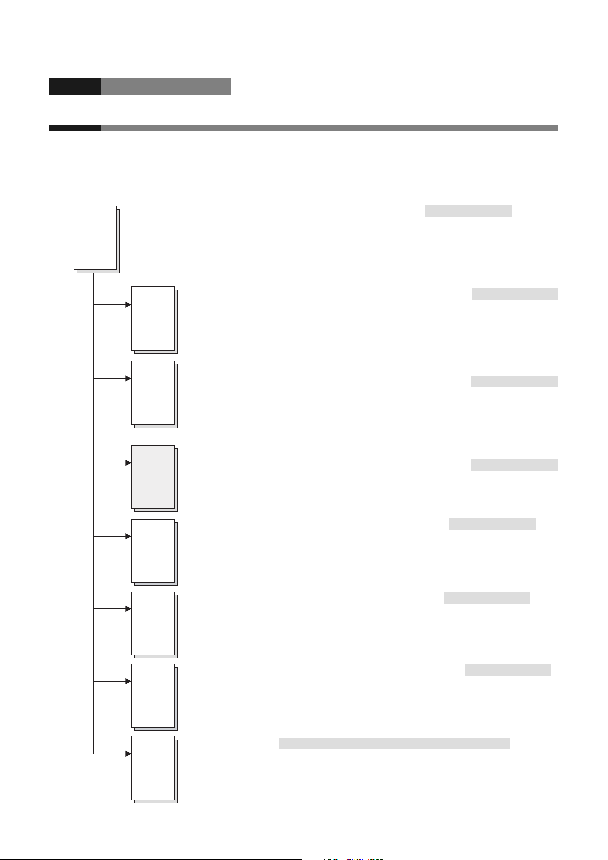
1. When using FX3U/FX3UC/FX3G PLCs
QCPU/FXCPU Structured Programming Manual (Fundamentals)
Q/FX
Structured
This manual explains programming methods, specifications, functions, etc. required to create
structured programs.
(Additional Manual)
FX
Structured
FX
Structured
(This manual)
FX
Structured
FX
3U
FX
3UC
FX
3G
FXCPU Structured Programming Manual (Device & Common)
This manual explains devices and parameters for structured programs provided
by GX Works2.
(Additional Manual)
FXCPU Structured Programming Manual (Basic & Applied Instruction)
(Additional Manual)
This manual explains sequence instructions for structured programs provided
by GX Works2.
FXCPU Structured Programming Manual (Application Functions)
(Additional Manual)
This manual explains application functions for structured programs provided
by GX Works2.
FX3G/FX3U/FX
This manual explains details of analog special function blocks and analog special
adapters for FX
Explanation of instructions and instructions used in program examples are expressed
for GX Developer.
3UC
User's Manual- Analog Control Edition
3U
/FX
3UC
/FX3G PLCs and PID instruction.
(Additional Manual)
FX
FX
3U
FX
3UC
FX
3G
Special
unit/block
FX Series User's Manual -Data Communication Edition
This manual explains details of simple N:N link, parallel link, computer link, no-protocol
communication (RS and RS2 instructions), programming communication and inverter
communication for FX PLCs.
Explanation of instructions and instructions used in program examples are expressed
for GX Developer.
FX3G/FX3U/FX
This manual explains details of wiring, instructions and operations of the positioning
function built in FX
Explanation of instructions and instructions used in program examples are expressed
for GX Developer.
Individual manuals
This manual explains details of each special unit/block.
Explanation of instructions and instructions used in program examples are expressed
for GX Developer.
*1. Detailed explanation may be provided by a separate manual in some products.
3UC
Series User's Manual -Positioning Edition
3U
/FX
3UC
/FX3G PLC main units.
(Manual supplied with product or additional Manual )
(Additional Manual)
(Additional Manual)
*1
7
Page 10
FXCPU Structured Programming Manual
(Application Functions)
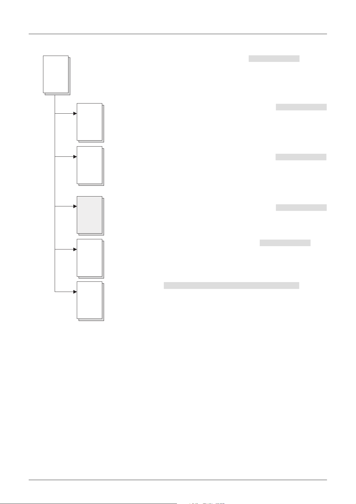
2. When using FX1S/FX1N/FXU/FX1NC/FX2NC PLCs
Q/FX
Structured
QCPU/FXCPU Structured Programming Manual (Fundamentals)
This manual explains programming methods, specifications, functions, etc. required to create
structured programs.
(Additional Manual)
FXCPU Structured Programming Manual (Device & Common)
FX
Structured
This manual explains devices and parameters for structured programs provided
by GX Works2.
FXCPU Structured Programming Manual (Basic & Applied Instruction)
FX
This manual explains sequence instructions for structured programs provided
Structured
by GX Works2.
(This manual)
FXCPU Structured Programming Manual (Application Functions)
FX
This manual explains application functions for structured programs provided
Structured
by GX Works2.
(Additional Manual)
(Additional Manual)
(Additional Manual)
FX
Special
unit/block
FX Series User's Manual -Data Communication Edition
This manual explains details of simple N:N link, parallel link, computer link, no-protocol
communication (RS instruction), programming communication and inverter communication
for FX PLCs.
Explanation of instructions and instructions used in program examples are expressed for
GX Developer and FX-PCS/WIN.
Individual manuals
This manual explains details of each special unit/block.
Explanation of instructions and instructions used in program examples are expressed
for GX Developer and FX-PCS/WIN.
*1. Detailed explanation may be provided by a separate manual in some products.
(Manual supplied with product or additional Manual )
(Additional Manual)
*1
8
Page 11

FXCPU Structured Programming Manual
(Application Functions)
3. When using FX0/FX0S/FX0N/FXU/FX2C PLCs
Q/FX
Structured
QCPU/FXCPU Structured Programming Manual (Fundamentals)
This manual explains programming methods, specifications, functions, etc. required to create
structured programs.
(Additional Manual)
FXCPU Structured Programming Manual (Device & Common)
FX
Structured
This manual explains devices and parameters for structured programs provided
by GX Works2.
FXCPU Structured Programming Manual (Basic & Applied Instruction)
FX
This manual explains sequence instructions for structured programs provided
Structured
by GX Works2.
(This manual)
FXCPU Structured Programming Manual (Application Functions)
FX
This manual explains application functions for structured programs provided
Structured
by GX Works2.
(Additional Manual)
(Additional Manual)
(Additional Manual)
FX
Special
unit/block
FX Series User's Manual -Data Communication Edition
This manual explains details of parallel link, computer link, no-protocol communication
(RS instruction) and programming communication for FX PLCs.
Explanation of instructions and instructions used in program examples are expressed for
GX Developer and FX-PCS/WIN.
Individual manuals
This manual explains details of each special unit/block.
Explanation of instructions and instructions used in program examples are expressed
for GX Developer and FX-PCS/WIN.
*1. Detailed explanation may be provided by a separate manual in some products.
(Manual supplied with product or additional Manual )
(Additional Manual)
*1
9
Page 12
FXCPU Structured Programming Manual
(Application Functions)
Related Manuals
This manual explains devices and parameters for structured programs provided by GX Works2.
Refer to other manuals for sequence instructions and applied functions.
This chapter introduces only reference manuals for this manual and manuals which describe the hardware
information of PLC main units.
Manuals not introduced here may be required in some applications.
Refer to the manual of the used PLC main unit and manuals supplied together with used products.
Contact the distributor for acquiring required manuals.
Common among FX PLCs [structured]
Manual name Manual number
QCPU/FXCPU Structured
Programming Manual (Fundamentals)
FXCPU Structured Programming
Manual (Device & Common)
FXCPU Structured Programming
Manual (Basic & Applied Instruction)
FXCPU Structured Programming
Manual (Application Functions)
3U/FX3UC/FX3G PLCs
FX
Manual name Manual number
PLC main unit
FX3U Series Hardware Manual JY997D18801 Supplied with product
FX3U Series User's Manual- Hardware
Edition
FX3UC (D, DSS) Series Hardware
Manual
FX3UC-32MT-LT-2 Hardware Manual JY997D31601 Supplied with product
FX3UC Series User's Manual Hardware Edition
FX3G Series Hardware Manual JY997D33401 Supplied with product
FX3G Series User's Manual- Hardware
Edition
SH-080782 Additional Manual
JY997D26001 Additional Manual
JY997D34701 Additional Manual
JY997D34801 Additional Manual
JY997D16501 Additional Manual
JY997D28601 Supplied with product
JY997D28701 Additional Manual
JY997D31301 Additional Manual
Supplied with product
or Additional Manual
Supplied with product
or Additional Manual
Contents
Programming methods, specifications, functions,
etc. required to create structured programs
Devices, parameters, etc. provided in structured
projects of GX Works2
Sequence instructions provided in structured
projects of GX Works2
Application functions provided in structured
projects of GX Works2
Contents
I/O specifications, wiring and installation of the
PLC main unit FX3U extracted from the FX3U
Series User’s Manual - Hardware Edition. For
detailed explanation, refer to the FX3U Series
User’s Manual - Hardware Edition.
Details about the hardware including I/O
specifications, wiring, installation and
maintenance of the FX3U PLC main unit.
I/O specifications, wiring and installation of the
PLC main unit FX3UC (D, DSS) extracted from the
FX3UC Series User’s Manual - Hardware Edition.
For detailed explanation, refer to the FX3UC
Series User’s Manual - Hardware Edition.
I/O specifications, wiring and installation of the
PLC main unit FX3UC-32MT-LT-2 extracted from
the FX3UC Series User’s Manual - Hardware
Edition. For detailed explanation, refer to the
FX3UC Series User’s Manual - Hardware Edition.
Details about the hardware including I/O
specifications, wiring, installation and
maintenance of the FX3UC PLC main unit.
I/O specifications, wiring and installation of the
PLC main unit FX3G extracted from the FX3G
Series User’s Manual - Hardware Edition. For
detailed explanation, refer to the FX3G Series
User’s Manual - Hardware Edition.
Details about the hardware including I/O
specifications, wiring, installation and
maintenance of the FX3G PLC main unit.
Model
name code
13JW06
09R920
09R921
09R922
Model
name code
-
09R516
-
-
09R519
-
09R521
10
Page 13

FXCPU Structured Programming Manual
(Application Functions)
Manual name Manual number
Programming
FX3G/FX3U/FX3UC User's ManualAnalog Control Edition
FX Series User's Manual -Data
Communication Edition
FX3G/FX3U/FX3UC Series User's
Manual -Positioning Edition
FX3U-CF-ADP User's Manual JY997D35401 Additional Manual
JY997D16701 Additional Manual
JY997D16901 Additional Manual
JY997D16801 Additional Manual
Supplied with product
or Additional Manual
FX1S/FX1N/FX2N/FX1NC/FX2NC PLCs
Manual name Manual number
PLC main unit
FX1S HARDWARE MANUAL JY992D83901 Additional Manual
FX1N HARDWARE MANUAL JY992D89301 Additional Manual
FX2N HARDWARE MANUAL JY992D66301 Additional Manual
FX1NC HARDWARE MANUAL JY992D92101 Additional Manual
FX2NC HARDWARE MANUAL JY992D76401 Additional Manual
Programming
FX Series User's Manual -Data
Communication Edition
JY997D16901 Additional Manual
Supplied with product
or Additional Manual
Contents
Detaileds about the analog special function block
(FX3U-4AD, FX3U-4DA, FX3UC-4AD) and analog
special adapter
(FX3U-****-ADP).
Details about simple N : N link, parallel link,
computer link and no-protocol communication
(RS instruction and FX2N-232IF).
Details about the positioning function built in the
FX3G/FX3U/FX3UC Series.
Describes details of the FX3U-CF-ADP CF card
special adapter.
Contents
Details about the hardware including I/O
specifications, wiring, installation and
maintenance of the FX1S PLC main unit.
Details about the hardware including I/O
specifications, wiring, installation and
maintenance of the FX1N PLC main unit.
Details about the hardware including I/O
specifications, wiring, installation and
maintenance of the FX2N PLC main unit.
Details about the hardware including I/O
specifications, wiring, installation and
maintenance of the FX1NC PLC main unit.
(Japanese only)
Details about the hardware including I/O
specifications, wiring, installation and
maintenance of the FX2NC PLC main unit.
Details about simple N : N link, parallel link,
computer link and no-protocol communication
(RS instruction and FX2N-232IF).
Model
name code
09R619
09R715
09R620
09R720
Model
name code
-
-
09R508
09R505
09R509
09R715
11
Page 14
FXCPU Structured Programming Manual
(Application Functions)
0/FX0S/FX0N/FXU/FX2C PLCs [whose production is finished]
FX
Manual name Manual number
PLC main unit
FX0/FX0N HARDWARE MANUAL JY992D47501 Supplied with product
FX0S HARDWARE MANUAL JY992D55301 Supplied with product
FX/FX2C HARDWARE MANUAL JY992D47401 Supplied with product
Programming
FX Series User's Manual -Data
Communication Edition
JY997D16901 Additional Manual
Supplied with product
or Additional Manual
Manuals of models whose production is finished
Production is finished for FX
0/FX0S/FX0N/FXU/FX2C PLCs.
Contents
Details about the hardware including I/O
specifications, wiring, installation and
maintenance of the FX0/FX0N PLC main unit.
Details about the hardware including I/O
specifications, wiring, installation and
maintenance of the FX0S PLC main unit.
Details about the hardware including I/O
specifications, wiring, installation and
maintenance of the FXU/FX2C PLC main unit.
Details about simple N : N link, parallel link,
computer link and no-protocol communication
(RS instruction and FX2N-232IF).
Model
name code
-
-
-
09R715
12
Page 15
FXCPU Structured Programming Manual
(Application Functions)
Generic Names and Abbreviations Used in Manuals
Abbreviation/generic name Name
PLCs
FX3U Series or FX3U PLC Generic name of FX3U Series PLCs
FX3UC Series or FX3UC PLC Generic name of FX3UC Series PLCs
FX3G Series or FX3G PLC Generic name of FX3G Series PLCs
FX2N Series or FX2N PLC Generic name of FX2N Series PLCs
FX2NC Series or FX2NC PLC Generic name of FX2NC Series PLCs
FX1N Series or FX1N PLC Generic name of FX1N Series PLCs
FX1NC Series or FX1NC PLC
FX1S Series or FX1S PLC Generic name of FX1S Series PLCs
FXU Series or FXU PLC Generic name of FXU(FX,FX2) Series PLCs
FX2C Series or FX2C PLC Generic name of FX2C Series PLCs
FX0N Series or FX0N PLC Generic name of FX0N Series PLCs
FX0S Series or FX0S PLC Generic name of FX0S Series PLCs
FX0 Series or FX0 PLC Generic name of FX0 Series PLCs
Special adapters
CF card special adapter Generic name of CF card special adapters
CF-ADP FX3U-CF-ADP
Programming language
ST Abbreviation of structured text language
Structured ladder Abbreviation of ladder diagram language
Manuals
Q/FX Structured Programming Manual
(Fundamentals)
FX Structured Programming Manual
(Device & Common)
FX Structured Programming Manual
(Basic & Applied Instruction)
FX Structured Programming Manual
(Application Functions)
COMMUNICATION CONTROL
EDITION
ANALOG CONTROL EDITION Abbreviation of FX3G/FX3U/FX3UC Series User's Manual-ANALOG CONTROL EDITION
POSITIONING CONTROL EDITION Abbreviation of FX
Generic name of FX1NC Series PLCs
These products can only used in Japan.
Abbreviation of QCPU/FXCPU Structured Programming Manual (Fundamentals)
Abbreviation of FXCPU Structured Programming Manual (Device & Common)
Abbreviation of FXCPU Structured Programming Manual (Basic & Applied Instruction)
Abbreviation of FXCPU Structured Programming Manual (Application Functions)
Abbreviation of FX Series User's Manual-DATA COMMUNICATION CONTROL EDITION
3G/FX3U/FX3UC Series User's Manual-POSITIONING CONTROL EDITION
13
Page 16

FXCPU Structured Programming Manual
(Application Functions)
1.1 Outline of Structured Programs and Programming
1. Outline
This manual explains applied functions for structured programs provided by GX Works2.
Refer to a different manual for devices, parameters and sequence instructions.
Refer to the following manual for labels, data types and programming languages for structured programs:
→ Q/FX Structured Programming Manual (Fundamentals)
1.1 Outline of Structured Programs and Programming Languages
1.1.1 Outline of structured programs
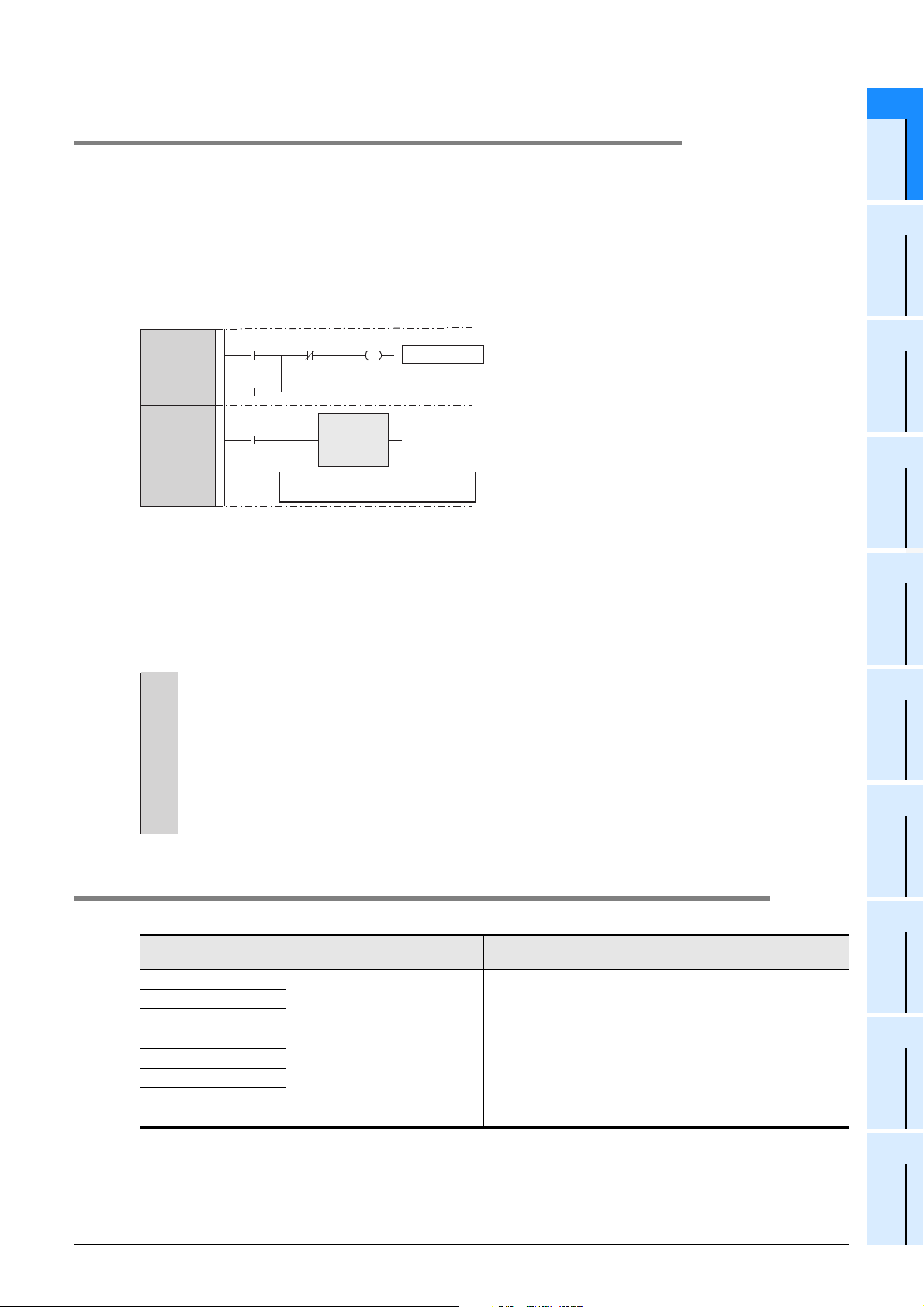
You can construct two or more programs (program blocks) into one program.
Because you can divide the entire machine processing into small sub processes and create a program for
each sub process, you can efficiently create a program for a large system.
1. Structured program
Program structuring is a technique to divide the contents of control executed by the PLC CPU into
hierarchical small units (blocks) of processing, and then construct a program. By using this technique, you
can design a program while recognizing structuring of a sequence program.
1 Outline
Advantages of hierarchical program
• You can examine the outline of a program at first, and then design its details gradually.
• Program blocks located at the lowest level in the hierarchy are extremely simple and highly independent.
Advantages of program consisting of program blocks
• Because the processing of each block is clear, the entire program is easy to understand.
• The entire program can be divided into several blocks that are created by several people.
• The program reusability is improved, and the development efficiency is improved accordingly.
2. Improved reusability of programs
You can save program blocks in a library. Program resources in the library can be shared, and often used
again.
14
Page 17
FXCPU Structured Programming Manual
(Application Functions)
1.1.2 Programming languages
The following programming languages can be used in each program block.
Graphic languages
1. Structured ladder language
This graphic language is created based on the relay circuit design technology.
Any circuit always starts from the bus line located on the leftmost.
The structured ladder language consists of contacts, coils, functions and function blocks. These components
are connected with vertical lines and horizontal lines.
1 Outline
1.2 PLC Series and Programming Software Version
1
2
Outline
Function List
1
2
X000 X001 Y000
Y000
X001
D0
When X001 is ON, the contents
of D0 are transferred to D2.
MOV
EN ENO
sd
Output Y000
D2
Text language
1. ST (Structured text) language
The ST language can describe control achieved by syntax using selective branches with conditional
statements and repetition by repetitive statements in the same way as high-level languages such as C
language.
By using the ST language, you can create simple programs easy to understand.
Y000:=(X000 OR Y000) AND NOT X001;
IF X001 THEN
D2:=D0; (When X001 is ON, the contents of D0 are transferred to D2.)
END_IF;
IF X002 THEN
D4:=D4+1; (When X002 is ON, the contents of D4 are added by "1".)
ELSE
D6:=D6+1; (When X002 is OFF, the contents of D6 are added by "1".)
END_IF;
3
Function
Construction
4
How to Read
Explanation of
Functions
5
Applied
Functions
6
Standard
Function Blocks
A
Correspondence
between Devices
and Addresses
1.2 PLC Series and Programming Software Version
PLC Series
FX3U•FX3UC
FX3G
FX2N•FX2NC
FX1N•FX1NC
FX1S
FXU/FX2C
FX0N
FX0•FX0S
Software package name
(model name)
GX Works2
(SW1DNC-GXW2-E)
Ver. 1.08J or later
GX Works2 version
15
Page 18
FXCPU Structured Programming Manual
(Application Functions)
1.3 Cautions on Creation of Fundamental Programs
1.3 Cautions on Creation of Fundamental Programs
This section explains cautions on programming.
Refer to the following manual for cautions on structured programs and programming languages:
→ Q/FX Structured Programming Manual (Fundamentals)
Refer to the following programming manual for detailed operations of and cautions on devices and
parameters:
→ FX Structured Programming Manual (Device & Common)
1.3.1 I/O processing and response delay
1. Operation timing of I/O relays and
response delay
FX PLCs execute the I/O processing by
repeating the processing (1) to processing (3).
Accordingly, the control executed by PLCs
contains not only the drive time of input filters
and output devices but also the response
delay caused by the operation cycle.
Acquiring the latest I/O information
For acquiring the latest input information or
immediately outputting the operation result in
the middle of the operation cycle shown
above, the I/O refresh instruction (REF) is
available.
(1)
Scan
time
(operation
cycle)
[Input processing]
Input image
memory is read.
(2)
[Program processing]
Image memory of
each device is updated.
Batch I/O method
(Refresh method)
The ON/OFF status of input
terminals is received at one time.
Input image is read, and
operation is executed
according to program.
(3)
[Output processing]
Result is transferred to
output latch memory.
Output
devices
are driven.
1 Outline
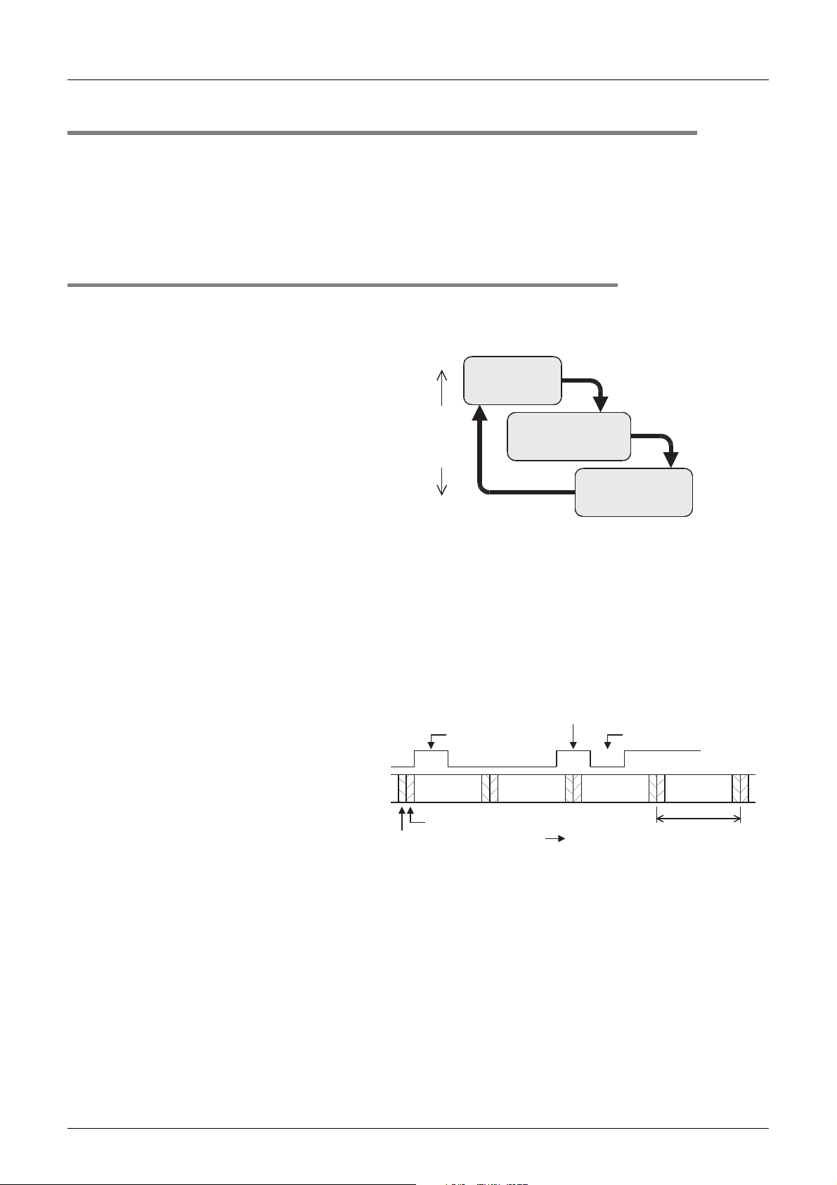
2. Short pulses cannot be received.
The ON duration and OFF duration of inputs in PLCs require longer time than "PLC cycle time + Input filter
response delay".
When the response delay "10 ms" of the input filter is considered and the cycle time is supposed as "10 ms",
the ON duration and OFF duration should be at least 20 ms respectively.
Accordingly, PLCs cannot handle input pulses at 25 Hz (= 1000 /(20 + 20)) or more. However, the situation
can be improved by PLC special functions and applied instructions.
Convenient functions for
improvement
By using the following functions, PLCs
can receive pulses shorter than the
operation cycle:
• High speed counter function
• Input interrupt function
• Pulse catch function
• Input filter value adjustment function
"Input ON" cannot
be received.
ON ON
Program
processing
Input processing
Output processing
This "input ON" can be received.
Program
processing
( Time)
This "input OFF" cannot
be received.
OFFOFF
Program
processing
Operation cycle
Program
processing
16
Page 19
FXCPU Structured Programming Manual
(Application Functions)
1.3 Cautions on Creation of Fundamental Programs
1.3.2 Double output (double coil) operation and countermeasures
This subsection explains the double output (double coil) operation and countermeasures.
1. Operation of double outputs
When a coil (output variable) is used twice (double coils) in another program block to be executed or in the
same program block, the PLC gives priority to the latter coil.
Suppose that the same coil Y003 is used in two positions as
shown in the right figure.
For example, suppose that X001 is ON and X002 is OFF.
Input processing
X001=ON X002=OFF
1 Outline
1
2
Outline
Function List
In the first coil Y003, the image memory is set to ON and the
output Y004 is also set to ON because the input X001 is ON.
In the second coil Y003, however, the image memory is set to
OFF because the input X002 is OFF.
As a result, the actual output to the outside is "Y003: OFF, Y004:
ON".
X001
Y003
X002
Output processing
Y003=OFF Y004=ON
First
Second
Y003
Y004
Y003
2. Countermeasures against double outputs
Double outputs (double coils) do not cause an illegal input error (program error), but the operation is
complicated as described above.
Change the program as shown in the example below.
A B
Y000
Ignored
A B
C E
D
Y000
3
Function
Construction
4
How to Read
Explanation of
Functions
5
Applied
Functions
6
Standard
Function Blocks
C E
D
The SET and RST instructions or jump instruction can be used instead, or a same output coil can be
programmed at each state using step ladder instructions STL and RET.
When you use the step ladder instructions STL and RET, note that the PLC regards it as double coils if you
program, inside the state, an output coil located outside the RET instruction from another program block or
the STL instruction.
Y000
Or
A B
C E
D
M100
M101
M100
M101
Y000
A
Correspondence
between Devices
and Addresses
17
Page 20
FXCPU Structured Programming Manual
(Application Functions)
1.3 Cautions on Creation of Fundamental Programs
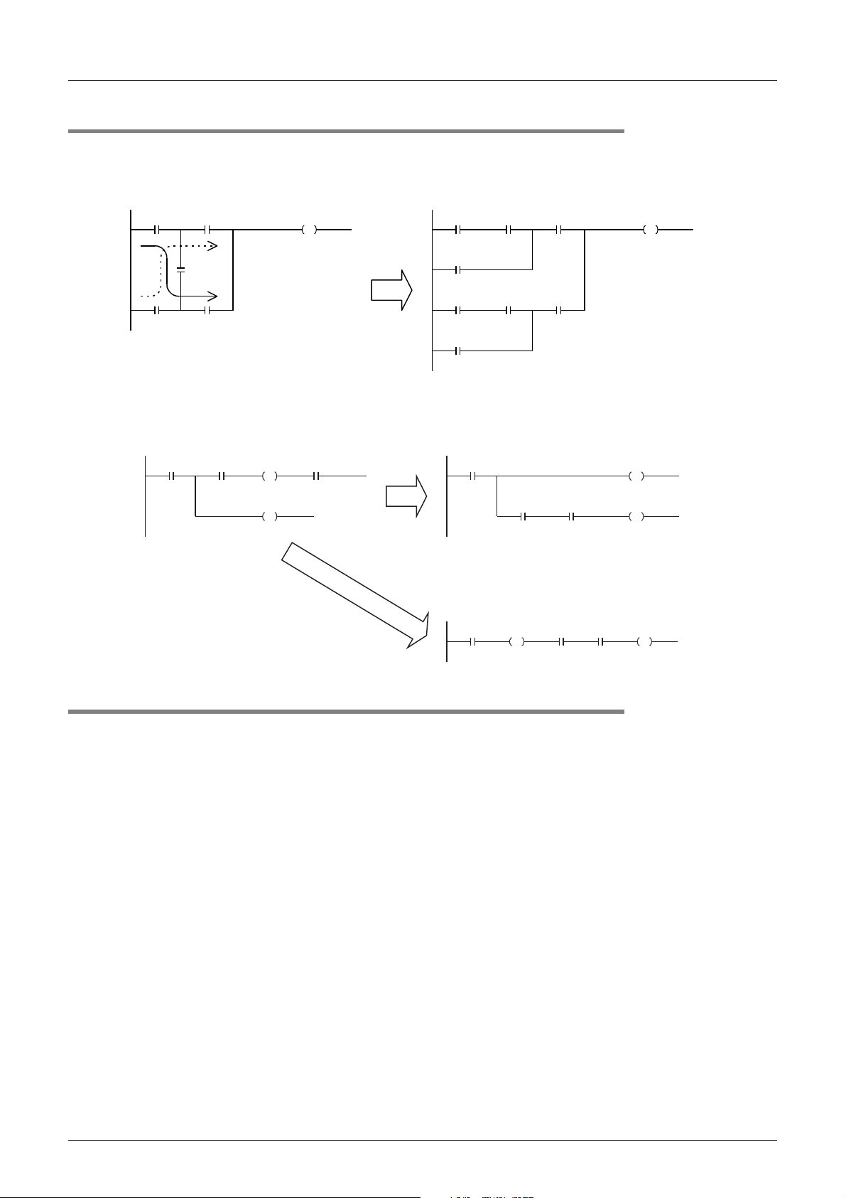
1.3.3 Circuits not available in structured ladder programs and countermeasures
1. Bridge circuit
A circuit in which the current flows in both directions should be changed as shown in the right figure (so that a
circuit without D and a circuit without B are connected in parallel).
A B
F F
C E
B
1 Outline
E
C
D
A
A E
C
D
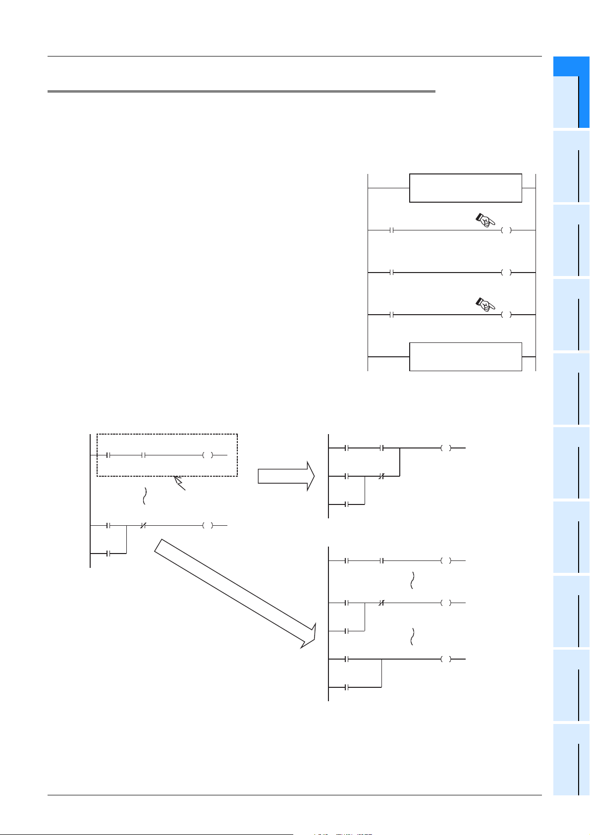
2. Coil connection position
• You can program a contact on the right side of a coil. In this case, make sure to program a coil (including a
function or function block) at the end of the circuit.
A B D A
C
Or
B D
AB
E
E
CE
D
C
1.3.4 Handling of general flags
The following flags are valid in general sequence instructions:
(Examples)
M8020:Zero flag M8021:Borrow flag M8022:Carry flag
M8029:Instruction execution complete flag M8090:Block comparison signal
M8328:Instruction non-execution flag
M8304:Zero flag
*1. Supported only in FX3U/FX3UC PLCs.
*2. Supported only in FX
Each of these flags turns ON or OFF every time the PLC executes a corresponding instruction. These flags
do not turn ON or OFF when the PLC does not execute a corresponding instruction or when an error occurs.
Because these flags are related to many sequence instructions, their ON/OFF status changes every time the
PLC executes each corresponding instruction.
Refer to examples in the next page, and program a flag contact just under the target sequence instruction.
*1
M8306:Carry flag
3U/FX3UC/FX3G PLCs.
*1
*1
*1
M8329:Instruction execution abnormal complete flag
*2
18
Page 21
FXCPU Structured Programming Manual
(Application Functions)
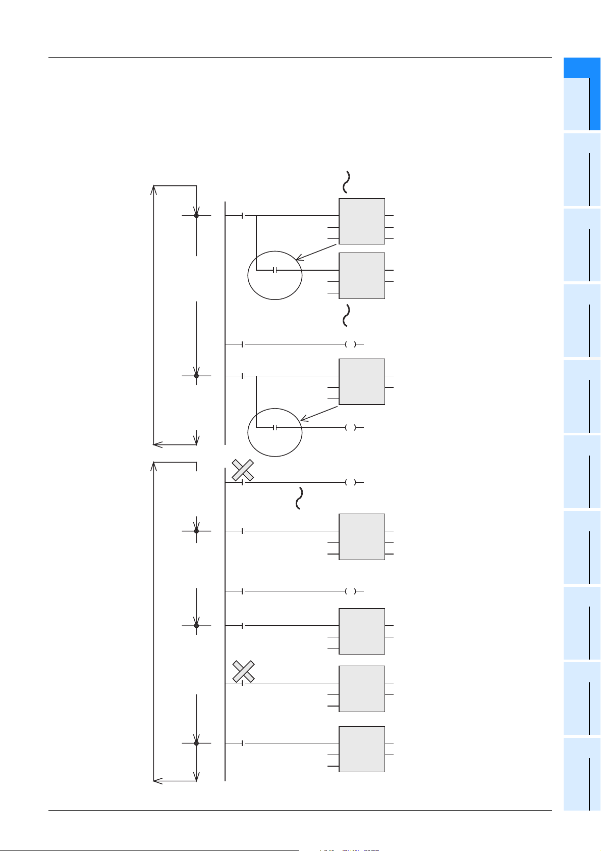
1. Program containing many flags (Example of instruction execution complete flag M8029)
If you program the instruction execution complete flag M8029 twice or more together for two or more
sequence instructions which actuate the flag M8029, you cannot judge easily by which sequence instruction
the flag M8029 is controlled. In addition, the flag M8029 does not turn ON or OFF correctly for each
corresponding sequence instruction.
Refer to the next page when you would like to use the flag M8029 in any position other than the position just
under the corresponding sequence instruction.
Good example
1.3 Cautions on Creation of Fundamental Programs
1 Outline
1
2
Outline
Function List
Bad example
M8029 works as
a flag to indicate
that execution of
DSW is completed.
M8029 works as
a flag to indicate
that execution of
DPLSY is
completed.
M8029 works as
a flag to indicate
that execution of
DPLSY (on the
lower side) is
completed.
M8029 works as
a flag to indicate
that execution of
DSW is completed.
M8000
M8029
Execution is
completed.
X000
M0
M8029
Execution is
completed.
M8029
Execution is
completed.
M8000
X000
ENs1ENO
X010
1D0
s2 d2
ENs1ENO
D0
s2
10
M0
S
DPLSY
ENs1ENO
1000 Y000
Number of
output pulses
X010
1
s2
M0
R
M0
R
ENs1ENO
s2 d2
M0
S
DSW
d1 Y010
MUL
Number of output pulses
d
d
Program for DPLSY (on the upper side)
DSW
Y010
d1
D0
3
Function
Construction
4
How to Read
Explanation of
Functions
5
Applied
Functions
6
Standard
Function Blocks
A
Correspondence
between Devices
and Addresses
M8029 works as a
flag to indicate that
execution of DPLSY
(on the upper side)
is completed.
M0
M8029
Execution is
completed.
M1
1000 Y000
Number of
output pulses
D0
10
Number of
output pulses2
1000 Y001
DPLSY
ENs1ENO
s2
MUL
ENs1ENO
s2
DPLSY
ENs1ENO
s2
DPLSY(on the upper side)
d
Program for DSW
d
Number of output pulses
DPLSY(on the lower side)
d
19
Page 22
FXCPU Structured Programming Manual
(Application Functions)
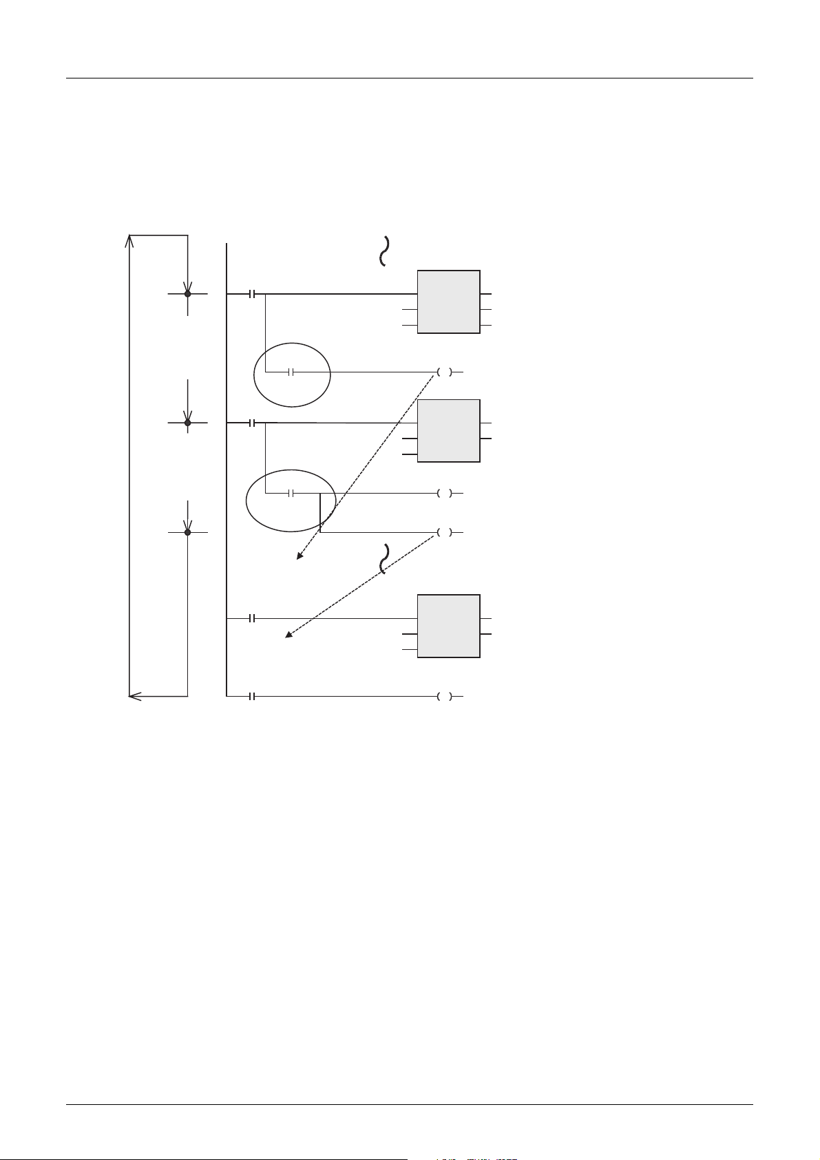
2. Introduction of a method to use flags in any positions other than positions just under
sequence instructions
If two or more sequence instructions are programmed, general flags turn ON or OFF when each
corresponding instruction is executed.
Accordingly, when using a general flag in any position other than a position just under a sequence instruction,
set to ON or OFF another device (variable) just under the sequence instruction, and then use the contact of
such device (variable) as the command contact.
1.3 Cautions on Creation of Fundamental Programs
1 Outline
DSW execution
complete flag
M8029 is changed
to M100.
DPLSY execution
complete flag
M8029 is changed
to M200.
M8000
M8029
Execution is
completed.
M0
Number of
output pulses
M8029
Execution is
completed.
It works as the DSW
execution complete flag.
M100
It works as the DPLSY
execution complete flag.
M200
DSW
ENs1ENO
Y010
M100
DPLSY
M0
R
M200
MUL
Y030
d1
D0
d
d
Number of output pulses
X010
s2 d2
1
ENs1ENO
1000 Y000
s2
ENs1ENO
D0
s2
10
20
Page 23
FXCPU Structured Programming Manual
(Application Functions)
1.3.5 Handling of operation error flag
When there is an error in the instruction construction, target device or target device number range and an
error occurs while operation is executed, the following flag turns ON and the error information is stored.
1 Outline
1.3 Cautions on Creation of Fundamental Programs
1
Outline
1. Operation error
Error flag
M8067 D8067
Device which stores
error code
FX0/FX0S/FX0N/FXU/FX2C/FX1S
/FX1N/FX2N/FX1NC/FX2NC/FX3G
*1. When an error occurs in a step up to the step No. 32767 in the FX3U/FX3UC PLC, you can check the
error occurrence step also in D8069 (16 bits).
• When an operation error has occurred, M8067 turns ON, D8067 stores the operation error code, and the
specified device (shown in the table above) stores the error occurrence step.
• When another error occurs in another step, the stored data is updated in turn to the error code and step
number of the new error. (These devices are set to OFF when errors are cleared.)
• When the PLC mode changes from STOP to RUN, these devices are cleared instantaneously, and then
turn ON again if errors have not been cleared.
Device which stores error occurrence step
FX3U/FX3UC
D8069
*1
D8315, D8314
2. Operation error latch
Error flag
M8068 -
Device which stores
error code
FX0/FX0S/FX0N/FXU/FX2C/FX1S
/FX1N/FX2N/FX1NC/FX2NC/FX3G
*2. When an error occurs in a step up to the step No. 32767 in the FX3U/FX3UC PLC, you can check the
error occurrence step also in D8068 (16 bits).
• When an operation error has occurred, M8068 turns ON, and the device shown in the table above stores
the error occurrence step.
• Even if another error occurs in another step, the stored data is not updated and remains held until these
devices are forcibly set to OFF or until the power is turned OFF.
Device which stores error occurrence step
FX3U/FX3UC
D8068
*2
D8313, D8312
2
Function List
3
Function
Construction
4
How to Read
Explanation of
Functions
5
Applied
Functions
6
Standard
Function Blocks
A
Correspondence
between Devices
and Addresses
21
Page 24
FXCPU Structured Programming Manual
(Application Functions)
2. Function List
This chapter introduces a list of functions available in programming.
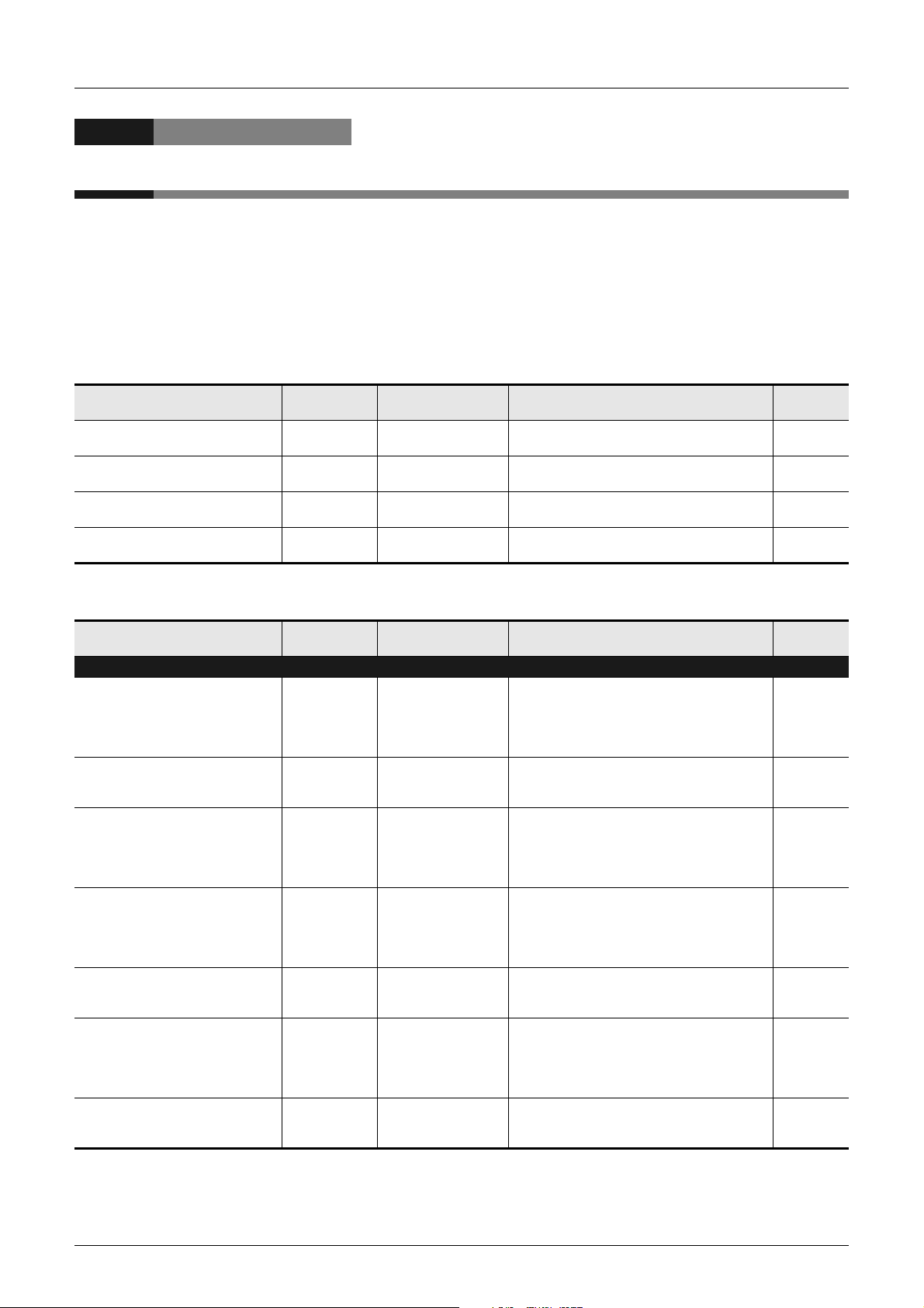
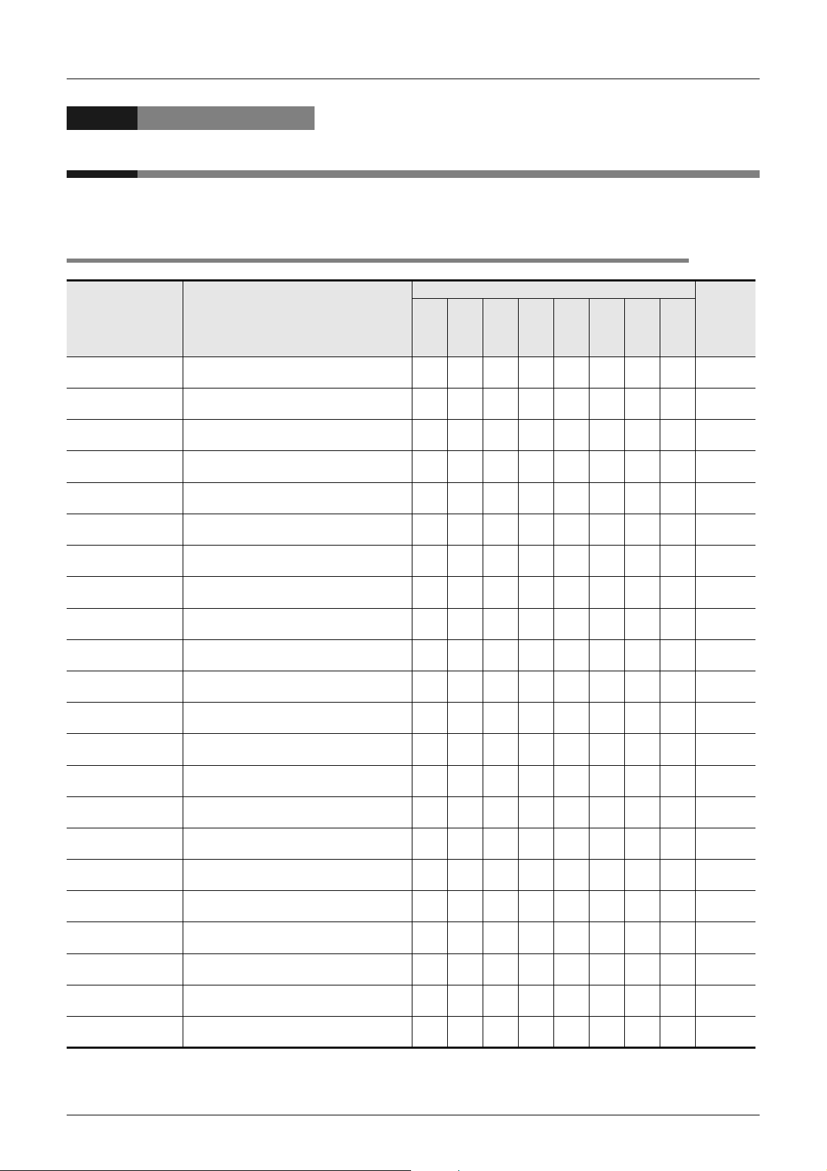
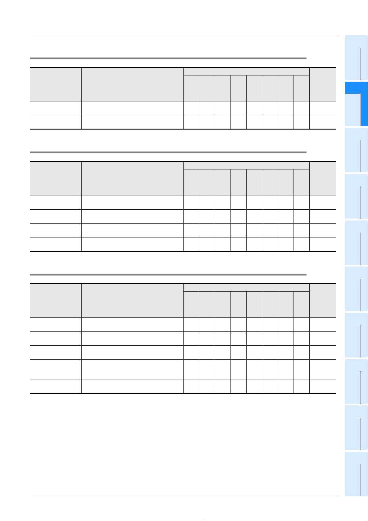
2.1 Type Conversion Functions
2 Function List
2.1 Type Conversion Functions
Applicable PLC
Function name Function
BOOL_TO_INT(_E) Converts bit data into word [signed] data. 33333333
BOOL_TO_DINT(_E) Converts bit data into double word [signed] data. 33333333
BOOL_TO_STR(_E) Converts bit data into string data. 3
BOOL_TO_WORD(_E)
BOOL_TO_DWORD
(_E)
BOOL_TO_TIME(_E) Converts bit data into time data. 33333333
INT_TO_DINT(_E)
DINT_TO_INT(_E)
INT_TO_BOOL(_E) Converts word [signed] data into bit data. 33333333
DINT_TO_BOOL(_E) Converts double word [signed] data into bit data. 33333333
INT_TO_REAL(_E)
DINT_TO_REAL(_E)
INT_TO_STR(_E) Converts word [signed] data into string data. 3
DINT_TO_STR(_E)
INT_TO_WORD(_E)
DINT_TO_WORD(_E)
INT_TO_DWORD(_E)
DINT_TO_DWORD
(_E)
INT_TO_BCD(_E) Converts word [signed] data into BCD data. 33333333
DINT_TO_BCD(_E)
INT_TO_TIME(_E) Converts word [signed] data into time data. 33333333
DINT_TO_TIME(_E)
Converts bit data into word [unsigned]/bit string
[16-bit] data.
Converts bit data into double word [unsigned]/bit
string [32-bit] data.
Converts word [signed] data into double word
[signed] data
Converts double word [signed] data into word
[signed] data.
Converts word [signed] data into float (single
precision) data.
Converts double word [signed] data into float
(single precision) data.
Converts double word [signed] data into string
data.
Converts word [signed] data into word
[unsigned]/bit string [16-bit] data.
Converts double word [signed] data into word
[unsigned]/bit string [16-bit] data.
Converts word [signed] data into double word
[unsigned]/bit string [32-bit] data.
Converts double word [signed] data into double
word [unsigned]/bit string[32-bit] data.
Converts double word [signed] data into BCD
data.
Converts double word [signed] data into time
data.
FX3U(C)
33333333
33333333
33333333
33333333
3 *1 3
3 *1 3
3
33333333
33333333
33333333
33333333
33333333
33333333
FX3G
FX2N(C)
FX1N(C)
FX1S
FXU/FX2C
FX0N
FX0(S)
*1. The function is provided in the FX3G Series Ver.1.10 or later.
Reference
Subsection
5.1.1
Subsection
5.1.2
Subsection
5.1.3
Subsection
5.1.4
Subsection
5.1.5
Subsection
5.1.6
Subsection
5.1.7
Subsection
5.1.8
Subsection
5.1.9
Subsection
5.1.10
Subsection
5.1.11
Subsection
5.1.12
Subsection
5.1.13
Subsection
5.1.14
Subsection
5.1.15
Subsection
5.1.16
Subsection
5.1.17
Subsection
5.1.18
Subsection
5.1.19
Subsection
5.1.20
Subsection
5.1.21
Subsection
5.1.22
22
Page 25
FXCPU Structured Programming Manual
(Application Functions)
Function name Function
FX3U(C)
FX3G
Applicable PLC
FX2N(C)
FX1N(C)
2 Function List
2.1 Type Conversion Functions
FX1S
FX
U
/FX
2C
FX0N
FX0(S)
Reference
1
Outline
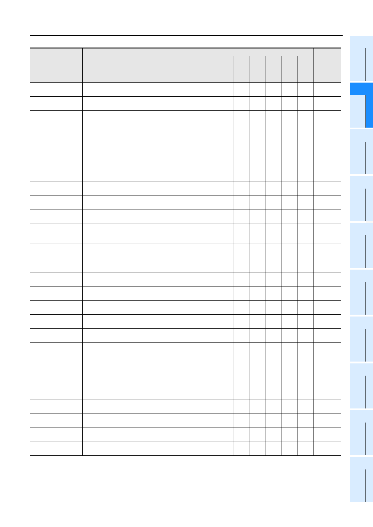
REAL_TO_INT(_E)
REAL_TO_DINT(_E)
REAL_TO_STR(_E)
WORD_TO_BOOL(_E)
DWORD_TO_BOOL
(_E)
WORD_TO_INT(_E)
WORD_TO_DINT(_E)
DWORD_TO_INT(_E)
DWORD_TO_DINT
(_E)
WORD_TO_DWORD
(_E)
DWORD_TO_WORD
(_E)
WORD_TO_TIME(_E)
DWORD_TO_TIME
(_E)
STR_TO_BOOL(_E) Converts string data into bit data. 3
STR_TO_INT(_E) Converts string data into word [signed] data. 3
STR_TO_DINT(_E)
STR_TO_REAL(_E)
STR_TO_TIME(_E) Converts string data into time data. 3
BCD_TO_INT(_E) Converts BCD data into word [signed] data. 33333333
BCD_TO_DINT(_E)
TIME_TO_BOOL(_E) Converts time data into bit data. 33333333
TIME_TO_INT(_E) Converts time data into word [signed] data. 33333333
TIME_TO_DINT(_E)
TIME_TO_STR(_E) Converts time data into string data. 3
TIME_TO_WORD(_E)
TIME_TO_DWORD
(_E)
Converts float (single precision) data into word
[signed] data.
Converts float (single precision) data into double
word [signed] data.
Converts float (single precision) data into string
data.
Converts word [unsigned]/bit string [16-bit] data
into bit data.
Converts double word [unsigned]/bit string [32bit] data into bit data.
Converts word [unsigned]/bit string [16-bit] data
into word [signed] data.
Converts word [unsigned]/bit string [16-bit] data
into double word [signed] data.
Converts double word [unsigned]/bit string [32bit] data into word [signed] data.
Converts double word [unsigned]/bit string [32bit] data into double word [signed] data.
Converts word [unsigned]/bit string [16-bit] data
into double word [unsigned]/bit string [32-bit].
Converts double word [unsigned]/bit string [32bit] data into word [unsigned]/bit string [16bit]data.
Converts word [unsigned]/bit string [16-bit] data
into time data.
Converts double word [unsigned]/bit string [32bit] data into time data.
Converts string data into double word [signed]
data.
Converts string data into float (single precision)
data.
Converts BCD data into double word [signed]
data.
Converts time data into double word [signed]
data.
Converts time data into word [unsigned]/bit
string [16-bit]data.
Converts time data into double word [unsigned]/
bit string [32-bit] data.
3 *1 3
3 *1 3
3
33333333
33333333
33333333
33333333
33333333
33333333
33333333
33333333
33333333
33333333
3
3
33333333
33333333
33333333
33333333
*1. The function is provided in the FX3G Series Ver.1.10 or later.
Subsection
5.1.23
Subsection
5.1.24
Subsection
5.1.25
Subsection
5.1.26
Subsection
5.1.27
Subsection
5.1.28
Subsection
5.1.29
Subsection
5.1.30
Subsection
5.1.31
Subsection
5.1.32
Subsection
5.1.33
Subsection
5.1.34
Subsection
5.1.35
Subsection
5.1.36
Subsection
5.1.37
Subsection
5.1.38
Subsection
5.1.39
Subsection
5.1.40
Subsection
5.1.41
Subsection
5.1.42
Subsection
5.1.43
Subsection
5.1.44
Subsection
5.1.45
Subsection
5.1.46
Subsection
5.1.47
Subsection
5.1.48
2
Function List
3
Function
Construction
4
How to Read
Explanation of
Functions
5
Applied
Functions
6
Standard
Function Blocks
A
Correspondence
between Devices
and Addresses
23
Page 26
FXCPU Structured Programming Manual
(Application Functions)
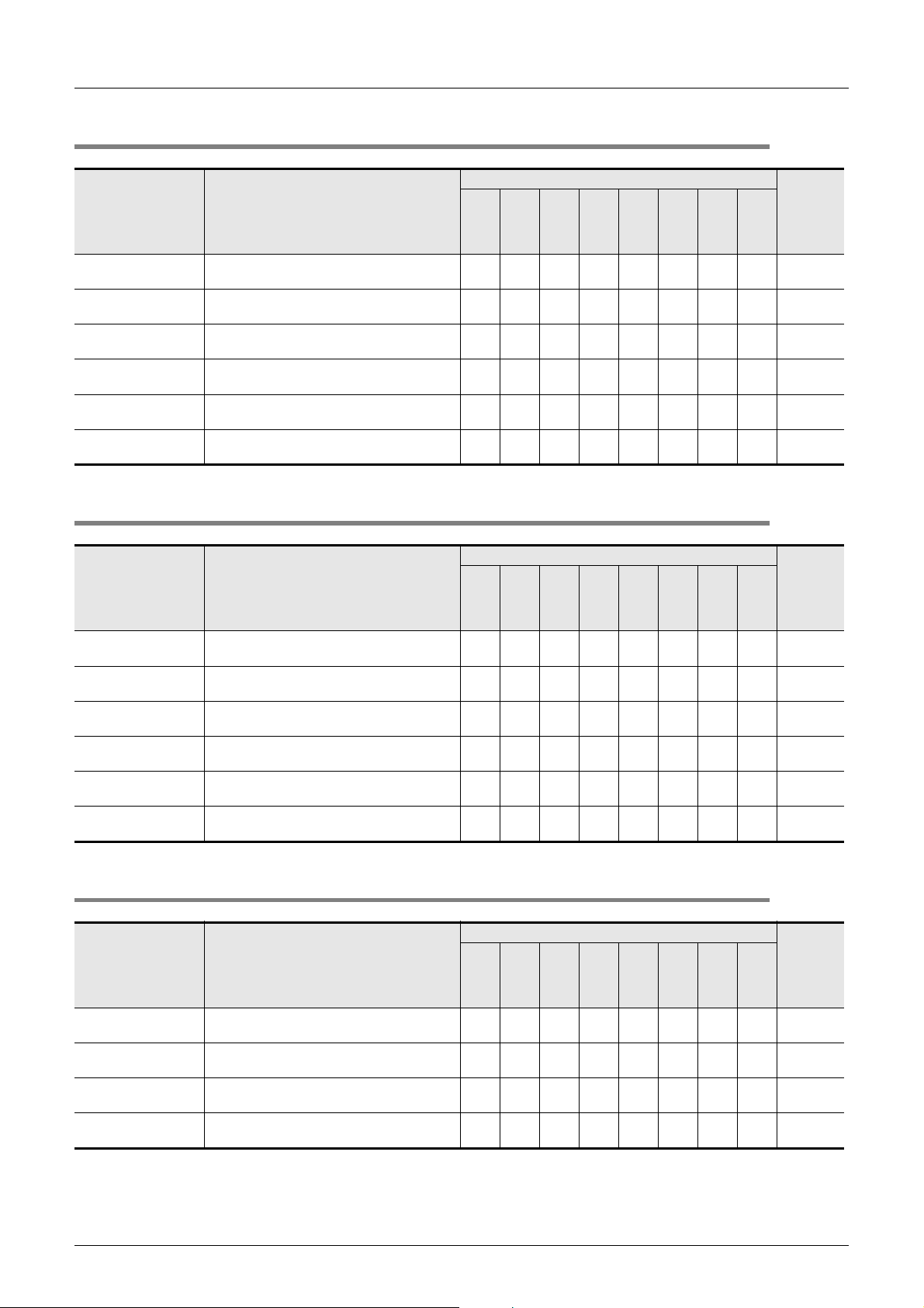
2.2 Standard Functions Of One Numeric Variable
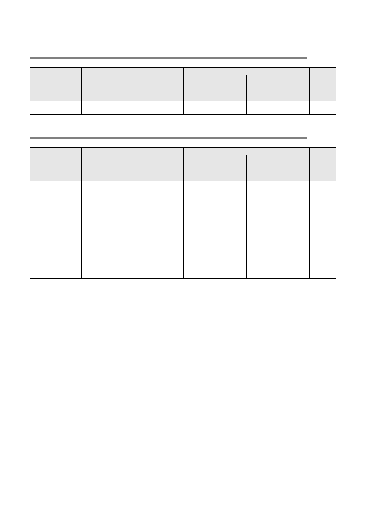
2.2 Standard Functions Of One Numeric Variable
2 Function List
Applicable PLC
Function name Function
FX3U(C)
ABS(_E) Obtains the absolute value. 33333333
FX3G
FX2N(C)
FX1N(C)
FX1S
FXU/FX2C
FX0N
FX0(S)
2.3 Standard Arithmetic Functions
Applicable PLC
Function name Function
FX3U(C)
ADD_E Adds data. 33333333
SUB_E Subtracts data. 33333333
MUL_E Multiplies data. 33333333
DIV_E Divides data (, and outputs the quotient). 33333333
MOD(_E) Divides data (, and outputs the remainder). 33333333
EXPT(_E) Obtains the raised result. 3
MOVE(_E) Transfers data. 33333333
FX3G
FX2N(C)
FX1N(C)
FX1S
FXU/FX2C
FX0N
FX0(S)
Reference
Subsection
5.2.1
Reference
Subsection
5.3.1
Subsection
5.3.2
Subsection
5.3.3
Subsection
5.3.4
Subsection
5.3.5
Subsection
5.3.6
Subsection
5.3.7
24
Page 27
FXCPU Structured Programming Manual
(Application Functions)
2.4 Standard Bit Shift Functions
2 Function List
2.4 Standard Bit Shift Functions
1
Outline
Applicable PLC
Function name Function
FX3U(C)
SHL(_E) Shifts bits leftward. 33333333
SHR(_E) Shifts bits rightward. 33333333
FX3G
FX2N(C)
FX1N(C)
FX1S
FXU/FX2C
FX0N
FX0(S)
2.5 Standard Bitwise Boolean Functions
Applicable PLC
Function name Function
FX3U(C)
AND_E Obtains the logical product. 33333333
OR_E Obtains the logical sum. 33333333
XOR_E Obtains the exclusive logical sum. 33333333
NOT(_E) Obtains the logical not. 33333333
FX3G
FX2N(C)
FX1N(C)
FX1S
FXU/FX2C
FX0N
FX0(S)
Reference
Subsection
5.4.1
Subsection
5.4.2
Reference
Subsection
5.5.1
Subsection
5.5.2
Subsection
5.5.3
Subsection
5.5.4
2
Function List
3
Function
Construction
4
How to Read
Explanation of
Functions
5
Applied
Functions
2.6 Standard Selection Functions
Applicable PLC
Function name Function
SEL(_E)
MAXIMUM(_E) Searches the maximum value. 33333333
MINIMUM(_E) Searches the minimum value. 33333333
LIMITATION(_E)
MUX(_E) Selects data, and outputs it. 33333333
Selects data in accordance with the input
condition.
Judges whether data is located within the range
between the upper limit value and the lower limit
value.
FX3U(C)
33333333
33333333
FX3G
FX2N(C)
FX1N(C)
FX1S
FX
U
/FX
2C
FX0N
FX0(S)
Reference
Subsection
5.6.1
Subsection
5.6.2
Subsection
5.6.3
Subsection
5.6.4
Subsection
5.6.5
6
Standard
Function Blocks
A
Correspondence
between Devices
and Addresses
25
Page 28
FXCPU Structured Programming Manual
(Application Functions)
2.7 Standard Comparison Functions
2 Function List
2.7 Standard Comparison Functions
Applicable PLC
Function name Function
GT_E Compares data with regard to "> (larger)". 33333333
GE_E
EQ_E Compares data with regard to "= (equal)". 33333333
LE_E
LT_E Compares data with regard to "< (smaller)". 33333333
NE_E Compares data with regard to "≠ (unequal)". 33333333
Compares data with regard to "≥ (larger or
equal)".
Compares data with regard to "≤ (smaller or
equal)".
FX3U(C)
33333333
33333333
FX3G
FX2N(C)
FX1N(C)
FX1S
FXU/FX2C
FX0N
FX0(S)
2.8 Standard Character String Functions
Function name Function
Applicable PLC
FX3U(C)
FX3G
FX2N(C)
FX1N(C)
FX1S
FXU/FX2C
FX0N
FX0(S)
Reference
Subsection
5.7.1
Subsection
5.7.2
Subsection
5.7.3
Subsection
5.7.4
Subsection
5.7.5
Subsection
5.7.6
Reference
MID(_E)
CONCAT(_E) Connects character strings. 3
INSERT(_E) Inserts a character string. 3
DELETE(_E) Deletes a character string. 3
REPLACE(_E) Replaces a character string. 3
FIND(_E) Searches a character string. 3
Obtains a character string from a specified
position.
3
2.9 Functions Of Time Data Types
Applicable PLC
Function name Function
FX3U(C)
ADD_TIME(_E) Adds time data. 33333333
SUB_TIME(_E) Subtracts time data. 33333333
MUL_TIME(_E) Multiplies time data. 33333333
DIV_TIME(_E) Divides time data. 33333333
FX3G
FX2N(C)
FX1N(C)
FX1S
FXU/FX2C
FX0N
FX0(S)
Subsection
5.8.1
Subsection
5.8.2
Subsection
5.8.3
Subsection
5.8.4
Subsection
5.8.5
Subsection
5.8.6
Reference
Subsection
5.9.1
Subsection
5.9.2
Subsection
5.9.3
Subsection
5.9.4
26
Page 29

FXCPU Structured Programming Manual
(Application Functions)
2.10 Standard Function Blocks
2 Function List
2.10 Standard Function Blocks
1
Outline
Applicable PLC
Function name Function
R_TRIG(_E)
F_TRIG(_E)
CTU(_E)
CTD(_E)
CTUD(_E)
TP(_E)
TON(_E)
TOF(_E)
COUNTER_FB_M Counter drive 33333333Section 6.9
TIMER_10_FB_M 10ms timer drive 33333333
TIMER_CONT_FB_M Retentive timer drive 3333 3
TIMER_100_M 100ms timer drive 33333333
Detects the rising edge of a signal, and outputs
pulse signal.
Detects the falling edge of a signal, and outputs
pulse signal.
Counts up the number of times of rising of a
signal.
Counts down the number of times of rising of a
signal.
Counts up/down the number of times of rising of
a signal.
Keeps ON a signal during specified time
duration.
Keeps OFF a signal during specified time
duration.
Turns OFF the output signal at specified time
after the input signal turned OFF.
FX3U(C)
33333333Section 6.1
33333333Section 6.2
333333 Section 6.3
333333 Section 6.4
333333 Section 6.5
333333 Section 6.6
333333 Section 6.7
333333 Section 6.8
FX3G
FX2N(C)
FX1N(C)
FX1S
FXU/FX2C
FX0N
FX0(S)
Reference
Section
6.10
Section
6.11
Section
6.12
2
Function List
3
Function
Construction
4
How to Read
Explanation of
Functions
5
Applied
Functions
6
Standard
Function Blocks
A
Correspondence
between Devices
and Addresses
27
Page 30
FXCPU Structured Programming Manual
(Application Functions)
3.1 Applied Function Expression and Execution Type
3. Function Construction
This chapter explains the construction of applied functions.
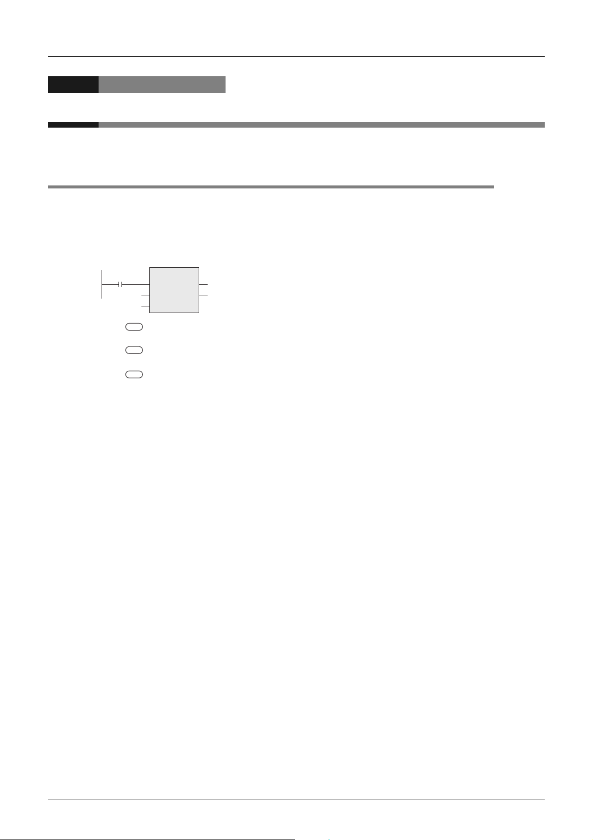
3.1 Applied Function Expression and Execution Type
Applied function and argument
• The name expressing the contents is given to each function.
For example, the function name "SHL (bit shift left)" is given.
• Each function consists of arguments which indicate I/O data used in the function.
SHL_E
EN ENO
D10D0 _IN
*1
_NK1
3 Function Construction
_IN ( ) : An argument whose contents do not change even if the function is executed is called
*1 ( ) : An argument whose contents change when the function is executed is called "destination",
K1 ( ) : Arguments not regarded as source or destination are expressed in "m", "n", etc.
s
"source", and expressed in this symbol.
d
and expressed in this symbol.
n
Argument target devices
• The input variable (label or device) specifies the target.
• Bit device themselves such as X, Y, M and S may be handled.
• Bit devices may be combined in a way "KnX", "KnY", "KnM" and "KnS" to express numeric data.
→ FX Structured Programming Manual (Device & Common)
• Current value registers of data registers (D), timers (T) and counters (C) may be handled.
• When handling 32-bit data in structured programs, you cannot specify 16-bit devices directly, different from
simple projects.
Use labels when handling 32-bit data.
You can specify 32-bit counters directly, however, because they have 32-bit length. Use global labels
when specifying devices.
When 32-bit data is handled, two consecutive 16-bit data registers D are combined.
For example, when data register D0 is defined as an argument of a 32-bit instruction by a label, 32-bit data
stored in D1 and D0 is handled. (D1 offers high-order 16 bits, and D0 offers low-order 16-bits.)
When the current value register of a timer or counter is used as a general data register, it is handled in the
same way.
28
Page 31

FXCPU Structured Programming Manual
(Application Functions)
3.2 Labels
Label types
Labels are classified into two types, global and local.
• Global labels can be used in program components and function blocks.
• Local labels can be used only in declared program blocks.
Label class
The label class indicates how each label can be used from which program component.
The table below shows label classes.
Class Description
VAR_GLOBAL Common label available in all program components 33
VAR_GLOBAL_CONSTANT Common constant available in all program components 33
VAR
VAR_CONSTANT
VAR_INPUT
VAR_OUTPUT Label output from a function block 3
VAR_IN_OUT
Label available within declared program components, and not
available in any other program component
Constant available within declared program components, and
not available in any other program component
Label which receives a value, and cannot be changed in
program components
Local label which receives a value, outputs it from a program
component, and can be changed in program components
3 Function Construction
3.2 Labels
Applicable program component
Program
block
333
333
Function
33
Function
block
3
1
Outline
2
Function List
3
Function
Construction
4
How to Read
Explanation of
Functions
5
Applied
Functions
Label definition
It is necessary to define a label to use the label.
An error will occur when a program in which labels are not defined is converted (compiled).
• When defining a global label, set the label name, class and data type, and assigns a device.
• When defining a local label, set the label name, class and data type.
You do not have to specify devices for local labels. Assignment of devices is automatically executed
during compiling.
In the example below, the label "VAR_D10" is set for the function "BOOL_TO_STR_E".
X000
• When using "VAR_D10" as a global label
Set the class, label name, data type and device (or address).
• When using "VAR_D10" as a local label
Set the class, label name and data type.
BOOL_TO_STR_E
EN ENO
_BOOL
M0
VAR_D10
6
Standard
Function Blocks
A
Correspondence
between Devices
and Addresses
29
Page 32

FXCPU Structured Programming Manual
(Application Functions)
Constant description method
The table below the description method required to set a constant to a label.
Constant type Description method Example
Bit Input "TRUE" or "FALSE". Or input "0" or "1". TRUE, FALSE
Binary number Add "2#" before a binary number. 2#0010, 2#01101010
Octal number Add "8#" before an octal number. 8#0, 8#337
Decimal number
Hexadecimal number Add "16#" or "H" before a hexadecimal number. 16#FF, HFF
Real number Input a real number directly. Or add "E" before a real number. 2.34, E2.34
Character string
Input a decimal number directly. Or add "K" before a decimal
number.
Surround a character string with single quotations (') or double
quotations (").
Data type
The label data type is basic or universal.
• The table below shows a list of basic data types.
Data type Description Value range Bit length
Bit Boolean data 0(FALSE), 1(TRUE) 1 bit
Word [signed] Integer -32768 to 32767 16 bits
Double Word [signed] Double precision integer
Word [unsigned]/Bit String
[16-bit]
Double Word [unsigned]/Bit
String [32-bit]
FLOAT (Single Precision) Real number
String Character string (50 characters maximum) Variable
Time Time value
16-bit data 0 to 65535 16 bits
32-bit data 0 to 4294967295 32 bits
-2147483648 to
2147483647
E ±1.175495
E ±3.402823
(Number of significant figures: 6)
T#-24d-0h31m23s648.00ms to
T#24d20h31m23s647.00ms
-38
+38
to
3 Function Construction
3.2 Labels
123, K123
'ABC', "ABC"
32 bits
32 bits
32 bits
30
Page 33

FXCPU Structured Programming Manual
(Application Functions)
• The universal data type indicates data type of a label which combines several basic data types.
The data type name begins with "ANY".
ANY_SIMPLE
ANY
3 Function Construction
3.2 Labels
*1 *1
Array Structure
1
2
Outline
Function List
ANY_NUM ANY_BIT
ANY_REAL
FLOAT
(Single
Precision)
FLOAT
(Double
Precision)
Word
[unsigned]/
Bit String
[16-bit]
ANY16
ANY_INT
Word
[signed]
Double word
[signed]
Word
[signed]
Bit
Word
[unsigned]/
Bit String
[16-bit]
Double Word
[unsigned]/
Bit String
[32-bit]
ANY32
Double Word
[unsigned]/
Bit String
[32-bit]
Time String
Double word
[signed]
The "ANY" type on a higher layer contains types
on the lower layer.
The "ANY" type on the top layer contains all types.
3
Function
Construction
4
How to Read
Explanation of
Functions
5
Applied
Functions
6
Standard
Function Blocks
*1 Refer to the following manual for details.
Q/FX Structured Programming Manual (Fundamentals)
A
Correspondence
between Devices
and Addresses
31
Page 34

FXCPU Structured Programming Manual
r
(Application Functions)
3.3 Device and Address
Devices can be described in two methods, device method and address method.
Device method
In this method, a device is described using the device name and device number.
X 0 D 100
3 Function Construction
3.3 Device and Address
Device name
Device number
Address method
This method is defined in IEC61131-3, and used as shown in the table below.
1st character:
Head
%
%I X 0 %M X 1 . 863
Memory area
position
Position
I Input (Omitted) Bit This number is provided for
QOutput X Bit
M Internal W Word (16 bits)
Size Classification Numbe
2nd character: Size
D Double word (32 bits)
L Long Word (64 bits)
• Memory area position
The memory area position in which data is assigned is classified into "input", "output" or "internal".
X(X Device method) : I(Input)
Y(Y Device method) : Q(Output)
Any other device : M(Internal)
•Size
The principle of the description method corresponding to the device method (MELSEC description method)
is as follows:
Bit device : X(Bit)
Word device : W(Word (16 bits)), D(Double word (32 bits))
• Classification
The 3rd and later characters indicate the device type which cannot be specified only by the position and
size explained above.
The classification is not required for devices "X" and "Y".
Refer to the following for the device description method:
3rd and later characters:
Classification
detailed classification.
Period (.) is used to delimit
the subsequent "Number".
The characters for
classification may be omitted.
Number
This decimal number
corresponds to the device
number.
→ 7.3 Appendix A
32
Page 35

FXCPU Structured Programming Manual
(Application Functions)
3.4 EN and ENO
Execution of an instruction can be controlled when the instruction contains "EN" in its name.
• "EN" inputs the instruction execution condition.
• "ENO" outputs the instruction execution status.
• The table below shows the "ENO" status corresponding to the "EN" status and the operation result.
EN ENO Operation result
TRUE(Executes operation.)
FALSE(Stops operation.) FALSE Indefinite value
TRUE(Operation error did not occur.) Operation output value
FALSE(Operation error occurred.) Indefinite value
3 Function Construction
3.4 EN and ENO
Construction
1
2
3
Outline
Function List
Function
X000
In the above example, the function "BOOL_TO_STR_E"
is executed only when X000 is "TRUE".
When the function is executed normally, "TRUE" is output to M1.
BOOL_TO_STR_E
EN ENO
_BOOL
M1
VAR_D10
4
How to Read
Explanation of
Functions
5
Applied
Functions
6
Standard
Function Blocks
A
Correspondence
between Devices
and Addresses
33
Page 36

FXCPU Structured Programming Manual
4 How to Read Explanation of Functions
(Application Functions)
4. How to Read Explanation of Functions
Function explanation pages have the following configuration.
1)
2)
3)
4)
5)
6)
7)
34
* The above page is prepared for explanation, and is different from the actual page.
Page 37

FXCPU Structured Programming Manual
(Application Functions)
1) Indicates the chapter/section/subsection number and instruction name.
2) Indicates PLCs which support the function.
Item Description
The PLC Series supports the function from its first product.
The supporting status varies on the version.
Applicable versions are explained in "Cautions".
The PLC Series does not support the function.
3) Indicates the expression of each function.
Item Description
Structured ladder Indicates the instruction expression in the structured ladder language.
ST Indicates the instruction expression in the ST language.
4) Indicates the input variable name and output variable name of the function as well as the contents and
data type of each variable.
Refer to the following for detailed data types:
5) Explanation of function and operation
The function executed by this function is explained.
In explanation, the structured ladder language is used as the representative.
6) Cautions
Cautions on using the function are described.
7) Program example
Program examples are explained in each language.
4 How to Read Explanation of Functions
→ Q/FX Structured Programming Manual (Fundamentals)
1
Outline
2
Function List
3
Function
Construction
4
How to Read
Explanation of
Functions
5
Applied
Functions
6
Standard
Function Blocks
A
Correspondence
between Devices
and Addresses
35
Page 38

FXCPU Structured Programming Manual
(Application Functions)
5. Applied Functions
This chapter explains the operation outline of each applied function, symbols, I/O data type, equivalent circuit
in sequence instructions, target models, cautions and program examples.
Refer to the following manual for variables, operators, data types and program languages:
5.1 Type Conversion Functions
5.1.1 BOOL_TO_INT(_E)
5 Applied Functions
5.1 Type Conversion Functions
→ Q/FX Structured Programming Manual (Fundamentals)
FX3U(C) FX3G FX2N(C) FX1N(C) FX1S
FXU/FX
Outline
This function coverts bit data into word [signed] data, and outputs the data obtained by conversion.
1. Format
Function name
BOOL_TO_INT
BOOL_TO_INT_E
*1. Output variable
2. Set data
Input
variable
Output
variable
Structured ladder ST
X000
M0
Variable Description Data type
EN Execution condition Bit
_BOOL ( )
ENO Execution status Bit
*1 ( )
s
d
Conversion source bit data Bit
Word [signed] data after conversion Word [signed]
Expression in each language
BOOL_TO_INT
_BOOL *1
BOOL_TO_INT_E
EN ENO
_BOOL
*1
D0M0
D0
BOOL_TO_INT(_BOOL);
Example:
D0:=
BOOL_TO_INT(M0);
BOOL_TO_INT_E(EN,_BOOL,
Output label
Example:
BOOL_TO_INT_E(X000,M0,
D0);
2C
FX0N FX0(S)
In explanation of functions, I/O variables inside ( ) are described.
Explanation of function and operation
This function converts bit data stored in a device specified in into word [signed] data, and outputs the
data obtained by conversion to a device specified in .
When the input value is "FALSE", this function outputs "0" as the word [signed] data value.
When the input value is "TRUE", this function outputs "1" as the word [signed] data value.
FALSE 0
TRUE 1
Bit data Word [signed] data
Cautions
Use the function having "_E" in its name to connect a bus.
36
s
d
Page 39

FXCPU Structured Programming Manual
(Application Functions)
Program example
In this program, bit data stored in a device specified in is converted into word [signed] data, and the data
obtained by conversion is output to a device specified in .
1) Function without EN/ENO(BOOL_TO_INT)
[Structured ladder]
g_bool1
2) Function with EN/ENO(BOOL_TO_INT_E)
[Structured ladder]
g_bool1
g_bool2
BOOL_TO_INT
_BOOL
BOOL_TO_INT_E
EN ENO
_BOOL
g_int1
g_bool3
g_int1
5 Applied Functions
5.1 Type Conversion Functions
s
d
[ST]
g_int1 := BOOL_TO_INT(g_bool1);
[ST]
g_bool3 := BOOL_TO_INT_E(g_bool1, g_bool2, g_int1);
Functions
1
Outline
2
Function List
3
Function
Construction
4
How to Read
Explanation of
5
Applied
Functions
6
Standard
Function Blocks
A
Correspondence
between Devices
and Addresses
37
Page 40

FXCPU Structured Programming Manual
(Application Functions)
5.1.2 BOOL_TO_DINT(_E)
5 Applied Functions
5.1 Type Conversion Functions
FX3U(C) FX3G FX2N(C) FX1N(C) FX1S
FXU/FX
2C
Outline
This function converts bit data into double word [signed] data, and outputs the data obtained by conversion.
1. Format
Function name
BOOL_TO_DINT
BOOL_TO_DINT_
E
*1. Output variable
2. Set data
Input
variable
Output
variable
Structured ladder ST
_BOOL *1
M0
X000
Variable Description Data type
EN Execution condition Bit
_BOOL ( )
ENO Execution status Bit
*1 ( )
s
d
BOOL_TO_DINT_E
EN ENO
_BOOL
M0
Conversion source bit data Bit
Double word [signed] data after conversion Double Word [signed]
Expression in each language
BOOL_TO_DINT
*1
Label
Label
BOOL_TO_DINT(_BOOL);
Example:
Label:=
BOOL_TO_DINT(M0);
BOOL_TO_DINT_E(EN,
_BOOL, Output label);
Example:
BOOL_TO_DINT_E(X000,M0,
Label);
FX0N FX0(S)
In explanation of functions, I/O variables inside ( ) are described.
Explanation of function and operation
This function converts bit data stored in a device specified in into double word [signed] data, and outputs
the data obtained by conversion to a device specified in .
FALSE 0
TRUE 1
Bit data Double word [signed] data
s
d
Cautions
1) Use the function having "_E" in its name to connect a bus.
2) When handling 32-bit data in structured programs, you cannot specify 16-bit devices directly, different
from simple projects. Use labels when handling 32-bit data.
You can specify 32-bit counters directly, however, because they are 32-bit devices.
Use global labels when specifying labels.
38
Page 41

FXCPU Structured Programming Manual
(Application Functions)
Program example
In this program, bit data stored in a device specified in is converted into double word [signed] data, and
the data obtained by conversion is output to a device specified in .
1) Function without EN/ENO(BOOL_TO_DINT)
[Structured ladder]
g_bool1
BOOL_TO_DINT
_BOOL
g_dint1
5.1 Type Conversion Functions
s
d
[ST]
g_dint1 := BOOL_TO_DINT(g_bool1);
5 Applied Functions
1
2
Outline
Function List
2) Function with EN/ENO(BOOL_TO_DINT_E)
[Structured ladder]
g_bool1
g_bool2
BOOL_TO_DINT_E
EN ENO
_BOOL
g_bool3
g_dint1
[ST]
g_bool3 := BOOL_TO_DINT_E(g_bool1, g_bool2, g_dint1);
3
Function
Construction
4
How to Read
Explanation of
Functions
5
Applied
Functions
6
Standard
Function Blocks
A
Correspondence
between Devices
and Addresses
39
Page 42

FXCPU Structured Programming Manual
(Application Functions)
5.1.3 BOOL_TO_STR(_E)
5 Applied Functions
5.1 Type Conversion Functions
FX3U(C) FX3G FX2N(C) FX1N(C) FX1S
Outline
This function converts bit data into string data, and outputs the data obtained by conversion.
1. Format
Function name
BOOL_TO_STR
BOOL_TO_STR_
E
*1. Output variable
2. Set data
Input
variable
Output
variable
Structured ladder ST
BOOL_TO_STR
_BOOL *1
X000
Variable Description Data type
EN Execution condition Bit
_BOOL ( )
ENO Execution status Bit
*1 ( )
s
d
BOOL_TO_STR_E
EN ENO
_BOOL
M0
Conversion source bit data Bit
String data after conversion String
Expression in each language
BOOL_TO_STR(_BOOL);
Example:
LabelM0
Label
*1
Label:=
BOOL_TO_STR(M0);
BOOL_TO_STR_E(EN,
_BOOL, Output label);
Example:
BOOL_TO_STR_E(X000,M0,
Label);
FXU/FX
2C
FX0N FX0(S)
In explanation of functions, I/O variables inside ( ) are described.
Explanation of function and operation
This function converts bit data input to a deice specified in into string data, and outputs the data obtained
by conversion to a device specified in .
FALSE "0"
TRUE "1"
Bit data String data
d
s
Cautions
1) Use the function having "_E" in its name to connect a bus.
2) When handling string data in structured programs, you cannot specify 16-bit devices directly, different
from simple projects. Use labels when handling string data. Use global labels when specifying labels.
40
Page 43
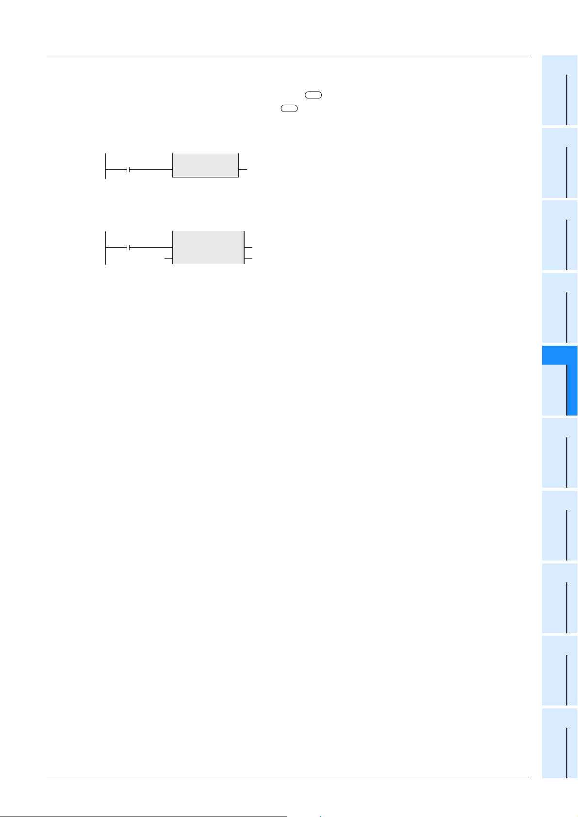
FXCPU Structured Programming Manual
(Application Functions)
Program example
In this program, bit data stored in a deice specified in is converted into string data, and the data obtained
by conversion is output to a device specified in .
1) Function without EN/ENO(BOOL_TO_STR)
[Structured ladder]
g_bool1
2) Function with EN/ENO(BOOL_TO_STR_E)
[Structured ladder]
g_bool1
g_bool2
BOOL_TO_STR
_BOOL
BOOL_TO_STR_E
EN ENO
_BOOL
g_string1
g_bool3
g_string1
5 Applied Functions
5.1 Type Conversion Functions
s
d
[ST]
g_string1 := BOOL_TO_STR(g_bool1);
[ST]
g_bool3 := BOOL_TO_STR_E(g_bool1, g_bool2, g_string1);
Functions
1
Outline
2
Function List
3
Function
Construction
4
How to Read
Explanation of
5
Applied
Functions
6
Standard
Function Blocks
A
Correspondence
between Devices
and Addresses
41
Page 44

FXCPU Structured Programming Manual
(Application Functions)
5.1.4 BOOL_TO_WORD(_E)
5 Applied Functions
5.1 Type Conversion Functions
FX3U(C) FX3G FX2N(C) FX1N(C) FX1S
FXU/FX
2C
FX0N FX0(S)
Outline
This function converts bit data into word [unsigned]/bit string [16-bit] data, and outputs the data obtained by
conversion.
1. Format
Function name
BOOL_TO_WOR
D
BOOL_TO_WOR
D_E
*1. Output variable
2. Set data
Input
variable
Output
variable
Structured ladder ST
M0 D0
X000
M0
Variable Description Data type
EN Execution condition Bit
_BOOL ( )
ENO Execution status Bit
*1 ( )
s
d
Conversion source bit data Bit
Word [unsigned]/bit string [16-bit] data after conversion
Expression in each language
BOOL_TO_WORD
_BOOL *1
BOOL_TO_WORD_E
EN ENO
_BOOL
BOOL_TO_WORD(_BOOL);
Example:
D0:=
BOOL_TO_WORD(M0);
BOOL_TO_WORD_E(EN,
_BOOL, Output label);
Example:
BOOL_TO_WORD_E(X000,
D0
*1
M0,D0);
Word [unsigned]/
Bit String [16-bit]
In explanation of functions, I/O variables inside ( ) are described.
Explanation of function and operation
This function converts bit data stored in a device specified in into word [unsigned]/bit string [16-bit] data,
and outputs the data obtained by conversion to a device specified in .
When the input value is "FALSE", this function outputs "0H" as the word [unsigned]/bit string [16-bit] data
value.
When the input value is "TRUE", this function outputs "1H" as the word [unsigned]/bit string [16-bit] data
value.
FALSE 0H
TRUE 1H
Bit data Word [unsigned]/
bit string [16-bit] data
s
d
Cautions
Use the function having "_E" in its name to connect a bus.
42
Page 45

FXCPU Structured Programming Manual
(Application Functions)
Program example
In this program, bit data stored in a device specified in is converted into word [unsigned]/bit string [16-bit]
data, and the data obtained by conversion is output to a device specified in .
1) Function without EN/ENO(BOOL_TO_WORD)
[Structured ladder]
g_bool1
2) Function with EN/ENO(BOOL_TO_WORD_E)
[Structured ladder]
g_bool1
g_bool2
BOOL_TO_WORD
_BOOL
BOOL_TO_WORD_E
EN ENO
_BOOL
g_word1
g_bool3
g_word1
5 Applied Functions
5.1 Type Conversion Functions
s
d
[ST]
g_word1 := BOOL_TO_WORD(g_bool1);
[ST]
g_bool3 := BOOL_TO_WORD_E(g_bool1, g_bool2, g_word1);
Functions
1
Outline
2
Function List
3
Function
Construction
4
How to Read
Explanation of
5
Applied
Functions
6
Standard
Function Blocks
A
Correspondence
between Devices
and Addresses
43
Page 46

FXCPU Structured Programming Manual
/
(Application Functions)
5.1.5 BOOL_TO_DWORD(_E)
5 Applied Functions
5.1 Type Conversion Functions
FX3U(C) FX3G FX2N(C) FX1N(C) FX1S
FXU/FX
2C
FX0N FX0(S)
Outline
This function converts bit data into double word [unsigned]/bit string [32-bit] data, and outputs the data
obtained by conversion.
1. Format
Function name
BOOL_TO_DWO
RD
BOOL_TO_DWO
RD_E
*1. Output variable
2. Set data
Input
variable
Output
variable
Structured ladder ST
BOOL_TO_DWORD
M0 Label
_BOOL *1
X000
Variable Description Data type
EN Execution condition Bit
_BOOL ( )
ENO Execution status Bit
*1 ( )
s
d
BOOL_TO_DWORD_E
EN ENO
_BOOL *1
M0
Conversion source bit data Bit
Double word [unsigned]/bit string [32-bit] data after conversion
Expression in each language
BOOL_TO_DWORD(_BOOL);
Example:
Label:=
BOOL_TO_DWORD(M0);
BOOL_TO_DWORD_E(EN,
_BOOL, Output label);
Example:
BOOL_TO_DWORD_E(X000,
Label
M0, Label);
Double Word [unsigned]/
Bit string [32-bit]
In explanation of functions, I/O variables inside ( ) are described.
Explanation of function and operation
This function converts bit data stored in a device specified in into double word [unsigned]/bit string [32bit] data, and outputs the data obtained by conversion to a device specified in .
When the input value is "FALSE", this function outputs "0H" as the double word [unsigned]/bit string [32bit]data value.
When the input value is "TRUE", this function outputs "1H" as the double word [unsigned]/bit string [32-bit]
data value.
FALSE 0H
TRUE 1H
Bit data Double Word [unsigned]
Bit string [32-bit] data
s
d
Cautions
1) Use the function having "_E" in its name to connect a bus.
2) When handling 32-bit data in structured programs, you cannot specify 16-bit devices directly, different
from simple projects. Use labels when handling 32-bit data.
You can specify 32-bit counters directly, however, because they are 32-bit devices.
Use global labels when specifying labels.
44
Page 47

FXCPU Structured Programming Manual
(Application Functions)
Program example
In this program, bit data stored in a device specified in is converted into double word [unsigned]/bit string
[32-bit] data, and the data obtained by conversion is output to a device specified in .
1) Function without EN/ENO(BOOL_TO_DWORD)
[Structured ladder]
g_bool1
[ST]
g_dword1 := BOOL_TO_DWORD(g_bool1);
2) Function with EN/ENO(BOOL_TO_DWORD_E)
[Structured ladder]
g_bool1
g_bool2
BOOL_TO_DWORD
_BOOL
BOOL_TO_DWORD_E
EN ENO
_BOOL
g_dword1
g_bool3
g_dword1
5 Applied Functions
5.1 Type Conversion Functions
1
Outline
s
d
2
Function List
3
Function
Construction
4
How to Read
Explanation of
Functions
[ST]
g_bool3 := BOOL_TO_DWORD_E(g_bool1, g_bool2, g_dword1);
5
Applied
Functions
6
Standard
Function Blocks
A
Correspondence
between Devices
and Addresses
45
Page 48

FXCPU Structured Programming Manual
(Application Functions)
5.1.6 BOOL_TO_TIME(_E)
5 Applied Functions
5.1 Type Conversion Functions
FX3U(C) FX3G FX2N(C) FX1N(C) FX1S
Outline
This function converts bit data into time data, and outputs the data obtained by conversion.
1. Format
Function name
BOOL_TO_TIME
BOOL_TO_TIME_
E
*1. Output variable
2. Set data
Input
variable
Output
variable
Structured ladder ST
M0 Label
_BOOL *1
X000
Variable Description Data type
EN Execution condition Bit
_BOOL ( )
ENO Execution status Bit
*1 ( )
s
d
BOOL_TO_TIME_E
EN ENO
_BOOL
M0
Conversion source bit data Bit
Time data after conversion Time
Expression in each language
BOOL_TO_TIME
*1
BOOL_TO_TIME(_BOOL);
Example:
Label:=
BOOL_TO_TIME(M0);
BOOL_TO_TIME_E(EN,_BOOL,
Output label);
Example:
BOOL_TO_TIME_E(X000,M0,
Label
Label);
FXU/FX
2C
FX0N FX0(S)
In explanation of functions, I/O variables inside ( ) are described.
Explanation of function and operation
This function converts bit data stored in a device specified in into time data, and outputs the data
obtained by conversion to a device specified in .
FALSE 0
TRUE 1ms
Bit data Time data
d
s
Cautions
1) Use the function having "_E" in its name to connect a bus.
2) When handling 32-bit data in structured programs, you cannot specify 16-bit devices directly, different
from simple projects. Use labels when handling 32-bit data.
You can specify 32-bit counters directly, however, because they are 32-bit devices.
Use global labels when specifying labels.
46
Page 49

FXCPU Structured Programming Manual
(Application Functions)
Program example
In this program, bit data stored in a device specified in is converted into time data, and the data obtained
by conversion is output to a device specified in .
1) Function without EN/ENO(BOOL_TO_TIME)
[Structured ladder]
g_bool1
BOOL_TO_TIME
_BOOL
g_time1
5.1 Type Conversion Functions
s
d
[ST]
g_time1 := BOOL_TO_TIME(g_bool1);
5 Applied Functions
1
2
Outline
Function List
2) Function with EN/ENO(BOOL_TO_TIME_E)
[Structured ladder]
g_bool1
g_bool2
BOOL_TO_TIME_E
EN ENO
_BOOL
g_bool3
g_time1
[ST]
g_bool3 := BOOL_TO_TIME_E(g_bool1, g_bool2, g_time1);
3
Function
Construction
4
How to Read
Explanation of
Functions
5
Applied
Functions
6
Standard
Function Blocks
A
Correspondence
between Devices
and Addresses
47
Page 50

FXCPU Structured Programming Manual
(Application Functions)
5.1.7 INT_TO_DINT(_E)
5 Applied Functions
5.1 Type Conversion Functions
FX3U(C) FX3G FX2N(C) FX1N(C) FX1S
FXU/FX
2C
FX0N FX0(S)
Outline
This function converts word [signed] data into double word [signed] data, and outputs the data obtained by
conversion.
1. Format
Function name
INT_TO_DINT
INT_TO_DINT_E
*1. Output variable
2. Set data
Input
variable
Output
variable
Structured ladder ST
D0 Label
_INT *1
X000
Variable Description Data type
EN Execution condition Bit
_INT ( )
ENO Execution status Bit
*1 ( )
s
d
EN ENO
_INT
D0
Conversion source word [signed] data Word [signed]
Double word [signed] data after conversion Double Word [signed]
Expression in each language
INT_TO_DINT
INT_TO_DINT_E
*1
INT_TO_DINT(_INT);
Example:
Label:=
INT_TO_DINT(D0);
INT_TO_DINT_E(EN,_INT,
Output label);
Example:
INT_TO_DINT_E(X000,D0,
Label
Label);
In explanation of functions, I/O variables inside ( ) are described.
Explanation of function and operation
This function converts word [signed] data stored in a device specified in into double word [signed] data,
and outputs the data obtained by conversion to a device specified in .
1234 1234
Word [signed] data Double word [signed] data
s
d
Cautions
1) Use the function having "_E" in its name to connect a bus.
2) When handling 32-bit data in structured programs, you cannot specify 16-bit devices directly, different
from simple projects. Use labels when handling 32-bit data.
You can specify 32-bit counters directly, however, because they are 32-bit devices.
Use global labels when specifying labels.
48
Page 51

FXCPU Structured Programming Manual
(Application Functions)
Program example
In this program, word [signed] data stored in a device specified in is converted into double word [signed]
data, and the data obtained by conversion is output to a device specified in .
1) Function without EN/ENO(INT_TO_DINT)
[Structured ladder]
INT_TO_DINT
_INT
5 Applied Functions
5.1 Type Conversion Functions
1
Outline
s
d
[ST]
g_dint1 := INT_TO_DINT(g_int1);
g_dint1=5923g_int1=5923
2
Function List
2) Function with EN/ENO(INT_TO_DINT_E)
[Structured ladder]
g_bool1
g_int1
INT_TO_DINT_E
EN ENO
_INT
g_bool3
g_dint1
[ST]
g_bool3 := INT_TO_DINT_E(g_bool1, g_int1, g_dint1);
3
Function
Construction
4
How to Read
Explanation of
Functions
5
Applied
Functions
6
Standard
Function Blocks
A
Correspondence
between Devices
and Addresses
49
Page 52

FXCPU Structured Programming Manual
(Application Functions)
5.1.8 DINT_TO_INT(_E)
5 Applied Functions
5.1 Type Conversion Functions
FX3U(C) FX3G FX2N(C) FX1N(C) FX1S
FXU/FX
2C
FX0N FX0(S)
Outline
This function converts double word [signed] data into word [signed] data, and outputs the data obtained by
conversion.
1. Format
Function name
DINT_TO_INT
DINT_TO_INT_E
*1. Output variable
2. Set data
Input
variable
Output
variable
Structured ladder ST
Label D10
X000
Label
Variable Description Data type
EN Execution condition Bit
_DINT ( )
ENO Execution status Bit
*1 ( )
s
d
_DINT *1
EN ENO
_DINT
Conversion source double word [signed] data Double Word [signed]
Word [signed] data after conversion Word [signed]
Expression in each language
DINT_TO_INT
DINT_TO_INT_E
*1
DINT_TO_INT(_DINT);
Example:
D10:=
DINT_TO_INT(Label);
DINT_TO_INT_E(EN,_DINT,
Output label);
Example:
DINT_TO_INT_E(X000, Label,
D10
D10);
In explanation of functions, I/O variables inside ( ) are described.
Explanation of function and operation
This function converts double word [signed] data stored in a device specified in into word [signed] data,
and outputs the data obtained by conversion to a device specified in .
1234 1234
Double word [signed] data Word [signed] data
d
s
Cautions
1) Use the function having "_E" in its name to connect a bus.
2) When handling 32-bit data in structured programs, you cannot specify 16-bit devices directly, different
from simple projects. Use labels when handling 32-bit data.
You can specify 32-bit counters directly, however, because they are 32-bit devices.
Use global labels when specifying labels.
50
Page 53

FXCPU Structured Programming Manual
(Application Functions)
Program example
In this program, double word [signed] data stored in a device specified in is converted into word [signed]
data, and the data obtained by conversion is output to a device specified in .
1) Function without EN/ENO(DINT_TO_INT)
[Structured ladder]
DINT_TO_INT
_DINT
5 Applied Functions
5.1 Type Conversion Functions
1
Outline
s
d
[ST]
g_int1 := DINT_TO_INT(g_dint1);
g_int1=5923g_dint1=5923
2
Function List
2) Function with EN/ENO(DINT_TO_INT_E)
[Structured ladder]
g_bool1
g_dint1
DINT_TO_INT_E
EN ENO
_DINT
g_bool3
g_int1
[ST]
g_bool3 := DINT_TO_INT_E(g_bool1, g_dint1, g_int1);
3
Function
Construction
4
How to Read
Explanation of
Functions
5
Applied
Functions
6
Standard
Function Blocks
A
Correspondence
between Devices
and Addresses
51
Page 54

FXCPU Structured Programming Manual
(Application Functions)
5.1.9 INT_TO_BOOL(_E)
5 Applied Functions
5.1 Type Conversion Functions
FX3U(C) FX3G FX2N(C) FX1N(C) FX1S
FXU/FX
Outline
This function converts word [signed] data into bit data, and outputs the data obtained by conversion.
1. Format
Function name
INT_TO_BOOL
INT_TO_BOOL_E
*1. Output variable
2. Set data
Input
variable
Output
variable
Structured ladder ST
X000
D0
Variable Description Data type
EN Execution condition Bit
_INT ( )
ENO Execution status Bit
*1 ( )
s
d
Conversion source word [signed] data Word [signed]
Bit data after conversion Bit
Expression in each language
INT_TO_BOOL
INT_TO_BOOL_E
EN ENO
_INT
*1
M0D0 *1_INT
M0
INT_TO_BOOL(_INT);
Example:
M0:=
INT_TO_BOOL(D0);
INT_TO_BOOL_E(EN,_INT,
Output label);
Example:
INT_TO_BOOL_E(X000,D0,M0);
2C
FX0N FX0(S)
In explanation of functions, I/O variables inside ( ) are described.
Explanation of function and operation
This function converts word [signed] data stored in a device specified in into bit data, and outputs the
data obtained by conversion to a device specified in .
d
When the input value is "0", this function outputs "FALSE".
When the input value is any value other than "0", this function outputs "TRUE".
0 FALSE
1567 TRUE
Word [signed] data Bit data
s
Cautions
Use the function having "_E" in its name to connect a bus.
52
Page 55

FXCPU Structured Programming Manual
(Application Functions)
Program example
In this program, word [signed] data stored in a device specified in is converted into bit data, and the data
obtained by conversion is output to a device specified in .
1) Function without EN/ENO(INT_TO_BOOL)
[Structured ladder]
INT_TO_BOOL
_INT
5 Applied Functions
5.1 Type Conversion Functions
1
Outline
s
d
[ST]
g_bool1 := INT_TO_BOOL(g_int1);
g_bool1g_int1=5923
2
Function List
2) Function with EN/ENO(INT_TO_BOOL_E)
[Structured ladder]
g_bool1
g_int1
INT_TO_BOOL_E
EN ENO
_INT
g_bool3
g_bool2
[ST]
g_bool3 := INT_TO_BOOL_E(g_bool1, g_int1, g_bool2);
3
Function
Construction
4
How to Read
Explanation of
Functions
5
Applied
Functions
6
Standard
Function Blocks
A
Correspondence
between Devices
and Addresses
53
Page 56

FXCPU Structured Programming Manual
(Application Functions)
5.1.10 DINT_TO_BOOL(_E)
5 Applied Functions
5.1 Type Conversion Functions
FX3U(C) FX3G FX2N(C) FX1N(C) FX1S
FXU/FX
2C
Outline
This function converts double word [signed] data into bit data, and outputs the data obtained by conversion.
1. Format
Function name
DINT_TO_BOOL
DINT_TO_BOOL_
E
*1. Output variable
2. Set data
Input
variable
Output
variable
Structured ladder ST
Label M0
X000
Label
Variable Description Data type
EN Execution condition Bit
_DINT ( )
ENO Execution status Bit
*1 ( )
s
d
_DINT *1
DINT_TO_BOOL_E
EN ENO
_DINT
Conversion source double word [signed] data Double Word [signed]
Bit data after conversion Bit
Expression in each language
DINT_TO_BOOL
*1
DINT_TO_BOOL(_DINT);
Example:
M0:=
DINT_TO_BOOL(Label);
DINT_TO_BOOL_E(EN,_DINT,
Output label);
Example:
DINT_TO_BOOL_E(X000, Label,
M0
M0);
FX0N FX0(S)
In explanation of functions, I/O variables inside ( ) are described.
Explanation of function and operation
This function converts double word [signed] data stored in a device specified in into bit data, and outputs
the data obtained by conversion to a device specified in .
d
When the input value is "0", this function outputs "FALSE".
When the input value is any value other than "0", this function outputs "TRUE".
0 FALSE
12345678 TRUE
Double word [signed] data Bit data
s
Cautions
1) Use the function having "_E" in its name to connect a bus.
2) When handling 32-bit data in structured programs, you cannot specify 16-bit devices directly, different
from simple projects. Use labels when handling 32-bit data.
You can specify 32-bit counters directly, however, because they are 32-bit devices.
Use global labels when specifying labels.
54
Page 57

FXCPU Structured Programming Manual
(Application Functions)
Program example
In this program, double word [signed] data stored in a device specified in is converted into bit data, and
the data obtained by conversion is output to a device specified in .
1) Function without EN/ENO(DINT_TO_BOOL)
[Structured ladder]
DINT_TO_BOOL
_DINT
[ST]
g_bool1 := DINT_TO_BOOL(g_dint1);
2) Function with EN/ENO(DINT_TO_BOOL_E)
[Structured ladder]
g_bool1g_dint1=0
5 Applied Functions
5.1 Type Conversion Functions
1
Outline
s
d
2
Function List
3
Function
Construction
g_bool1
g_dint1
[ST]
g_bool3 := DINT_TO_BOOL_E(g_bool1, g_dint1, g_bool2);
DINT_TO_BOOL_E
EN ENO
_DINT
g_bool3
g_bool2
4
How to Read
Explanation of
Functions
5
Applied
Functions
6
Standard
Function Blocks
A
Correspondence
between Devices
and Addresses
55
Page 58

FXCPU Structured Programming Manual
(Application Functions)
5.1.11 INT_TO_REAL(_E)
5 Applied Functions
5.1 Type Conversion Functions
FX3U(C) FX3G FX2N(C) FX1N(C) FX1S
FXU/FX
2C
FX0N FX0(S)
Outline
This function converts word [signed] data into float (single precision) data, and outputs the data obtained by
conversion.
1. Format
Function name
INT_TO_REAL
INT_TO_REAL_E
*1. Output variable
2. Set data
Input
variable
Output
variable
Structured ladder ST
a_Int *1
X000
Variable Description Data type
EN Execution condition Bit
a_Int ( )
ENO Execution status Bit
*1 ( )
s
d
INT_TO_REAL_E
EN ENO
a_Int
D0
Conversion source word [signed] data Word [signed]
Float (single precision) data after conversion FLOAT (Single Precision)
Expression in each language
INT_TO_REAL
*1
LabelD0
Label
INT_TO_REAL(a_Int);
Example:
Label:=
INT_TO_REAL(D0);
INT_TO_REAL_E(EN,a_Int,
Output label);
Example:
INT_TO_REAL_E(X000,D0,Label);
In explanation of functions, I/O variables inside ( ) are described.
Explanation of function and operation
This function converts word [signed] data stored in a device specified in into float (single precision) data,
and outputs the data obtained by conversion to a device specified in .
1234 1234.0
Word [signed] data Float (single precision) data
s
d
Cautions
1) Use the function having "_E" in its name to connect a bus.
2) When handling 32-bit data in structured programs, you cannot specify 16-bit devices directly, different
from simple projects. Use labels when handling 32-bit data.
You can specify 32-bit counters directly, however, because they are 32-bit devices.
Use global labels when specifying labels.
3) The function is provided in the FX
3G Series Ver.1.10 or later.
56
Page 59

FXCPU Structured Programming Manual
(Application Functions)
Program example
In this program, word [signed] data stored in a device specified in is converted into float (single
precision) data, and the data obtained by conversion is output to a device specified in .
1) Function without EN/ENO(INT_TO_REAL)
[Structured ladder]
g_int1=5923
2) Function with EN/ENO(INT_TO_REAL_E)
[Structured ladder]
g_bool1
g_int1
INT_TO_REAL
a_Int
INT_TO_REAL_E
EN ENO
a_Int
g_real1=5923.0
g_bool3
g_real1
5 Applied Functions
5.1 Type Conversion Functions
s
d
[ST]
g_real1 := INT_TO_REAL(g_int1);
[ST]
g_bool3 := INT_TO_REAL_E(g_bool1, g_int1, g_real1);
Functions
1
Outline
2
Function List
3
Function
Construction
4
How to Read
Explanation of
5
Applied
Functions
6
Standard
Function Blocks
A
Correspondence
between Devices
and Addresses
57
Page 60

FXCPU Structured Programming Manual
(Application Functions)
5.1.12 DINT_TO_REAL(_E)
5 Applied Functions
5.1 Type Conversion Functions
FX3U(C) FX3G FX2N(C) FX1N(C) FX1S
FXU/FX
2C
FX0N FX0(S)
Outline
This function converts double word [signed] data into float (single precision) data, and outputs the data
obtained by conversion.
1. Format
Function name
DINT_TO_REAL
DINT_TO_REAL_
E
*1. Output variable
2. Set data
Input
variable
Output
variable
Structured ladder ST
DINT_TO_REAL
Label 1 Label 2
X000
Label 1
Variable Description Data type
EN Execution condition Bit
a_Dint ( )
ENO Execution status Bit
*1 ( )
s
d
a_Dint *1
DINT_TO_REAL_E
EN ENO
a_Dint
Conversion source double word [signed] data Double Word [signed]
Float (single precision) data after conversion FLOAT (Single Precision)
Expression in each language
DINT_TO_REAL(a_Dint);
Example:
Label 2:=
DINT_TO_REAL(Label 1);
DINT_TO_REAL_E(EN,a_Dint,
Output label);
Example:
*1
Label 2
DINT_TO_REAL_E(X000, Label 1,
Label 2);
In explanation of functions, I/O variables inside ( ) are described.
Explanation of function and operation
This function converts double word [signed] data stored in a device specified in into float (single
precision) data, and outputs the data obtained by conversion to a device specified in .
16543521 16543521.0
Double word [signed] data Float (single precision) data
s
d
Cautions
1) Use the function having "_E" in its name to connect a bus.
2) When handling 32-bit data in structured programs, you cannot specify 16-bit devices directly, different
from simple projects. Use labels when handling 32-bit data.
You can specify 32-bit counters directly, however, because they are 32-bit devices.
Use global labels when specifying labels.
3) The function is provided in the FX
3G Series Ver.1.10 or later.
58
Page 61

FXCPU Structured Programming Manual
(Application Functions)
Program example
In this program, double word [signed] data stored in a device specified in is converted into float (single
precision) data, and the data obtained by conversion is output to a device specified in .
1) Function without EN/ENO(DINT_TO_REAL)
[Structured ladder]
g_dint1=65000
[ST]
g_real1 := DINT_TO_REAL(g_dint1);
2) Function with EN/ENO(DINT_TO_REAL_E)
[Structured ladder]
DINT_TO_REAL
a_Dint
g_real1=65000.0
5 Applied Functions
5.1 Type Conversion Functions
s
d
Construction
1
2
3
Outline
Function List
Function
g_bool1
g_dint1
[ST]
g_bool3 := DINT_TO_REAL_E(g_bool1, g_dint1, g_real1);
DINT_TO_REAL_E
EN ENO
a_Dint
g_bool3
g_real1
4
How to Read
Explanation of
Functions
5
Applied
Functions
6
Standard
Function Blocks
A
Correspondence
between Devices
and Addresses
59
Page 62

FXCPU Structured Programming Manual
(Application Functions)
5.1.13 INT_TO_STR(_E)
5 Applied Functions
5.1 Type Conversion Functions
FX3U(C) FX3G FX2N(C) FX1N(C) FX1S
FXU/FX
2C
Outline
This function converts word [signed] data into string data, and outputs the data obtained by conversion.
1. Format
Function name
INT_TO_STR
INT_TO_STR_E
*1. Output variable
2. Set data
Input
variable
Output
variable
Structured ladder ST
_INT *1
X000
Variable Description Data type
EN Execution condition Bit
_INT ( )
ENO Execution status Bit
*1 ( )
s
d
INT_TO_STR_E
EN ENO
D0
_INT
Conversion source word [signed] data Word [signed]
String data after conversion String
Expression in each language
INT_TO_STR
*1
LabelD0
Label
INT_TO_STR(_INT);
Example:
Label:=
INT_TO_STR(D0);
INT_TO_STR_E(EN,_INT,
Output label);
Example:
INT_TO_STR_E(X000, D0, Label);
FX0N FX0(S)
In explanation of functions, I/O variables inside ( ) are described.
Explanation of function and operation
1) This function converts word [signed] data stored in a device specified in into string data, and outputs
the data obtained by conversion to a device specified in .
High-order byte
ASCII code for ten-thousands place
ASCII code for hundreds place
ASCII code for ones place
Word [signed] data
Automatically stored at the end of the character string
d
Low-order byte
Sign data
ASCII code for thousands place
ASCII code for tens place
0000H
2) In "Sign data", "20H (space)" is stored when the input value is positive, and "2DH (-)" is stored when the
input value is negative.
3) "20H (space)" is stored in high-order digits when the number of significant figures is small.
Example: When "-123" is input
-123
Word [signed] data
High-order byte
20H (space)
31H (1) 20H (space)
33H (3)
0000H
Low-order byte
2DH (-)
32H (2)
4) "00H" is automatically stored at the end (4th word) of the character string.
s
String
1st word
2nd word
3rd word
4th word
String
1st word
2nd word
3rd word
4th word
Cautions
60
1) Use the function having "_E" in its name to connect a bus.
2) When handling string data in structured programs, you cannot specify 16-bit devices directly, different
from simple projects. Use labels when handling string data.
Use global labels when specifying labels.
Page 63

FXCPU Structured Programming Manual
(Application Functions)
Error
An operation error occurs in the following case. The error flag M8067 turns ON, and D8067 stores the error
code.
5 Applied Functions
5.1 Type Conversion Functions
1
Outline
1) When the number of points occupied by the string data storage destination (device specified in )
exceeds the range of the corresponding device
(Error code: K6706)
Program example
In this program, word [signed] data stored in a device specified in is converted into string data, and the
data obtained by conversion is output to a device specified in .
1) Function without EN/ENO(INT_TO_STR)
[Structured ladder]
g_int1=-12345
2) Function with EN/ENO(INT_TO_STR_E)
[Structured ladder]
g_bool1
g_int1
INT_TO_STR
_INT
INT_TO_STR_E
EN ENO
_INT
g_string='-12345'
g_bool3
g_string1
[ST]
g_string1 := INT_TO_STR(g_int1);
[ST]
g_bool3 := INT_TO_STR_E(g_bool1, g_int1, g_string1);
s
d
d
2
Function List
3
Function
Construction
4
How to Read
Explanation of
Functions
5
Applied
Functions
6
Standard
Function Blocks
A
Correspondence
between Devices
and Addresses
61
Page 64

FXCPU Structured Programming Manual
(Application Functions)
5.1.14 DINT_TO_STR(_E)
5 Applied Functions
5.1 Type Conversion Functions
FX3U(C) FX3G FX2N(C) FX1N(C) FX1S
FXU/FX
2C
FX0N FX0(S)
Outline
This function converts double word [signed] data into string data, and outputs the data obtained by
conversion.
1. Format
Function name
DINT_TO_STR
DINT_TO_STR_E
*1. Output variable
2. Set data
Input
variable
Output
variable
Structured ladder ST
Label 1 Label 2
X000
Label 1
Variable Description Data type
EN Execution condition Bit
_DINT ( )
ENO Execution status Bit
*1 ( )
s
d
_DINT *1
DINT_TO_STR_E
EN ENO
_DINT
Conversion source double word [signed] data Double Word [signed]
String data after conversion String
Expression in each language
DINT_TO_STR
*1
Label 2
DINT_TO_STR(_DINT);
Example:
Label 2:=
DINT_TO_STR(Label 1);
DINT_TO_STR_E(EN,_DINT,
Output label);
Example:
DINT_TO_STR_E(X000,
Label 1, Label 2);
In explanation of functions, I/O variables inside ( ) are described.
Explanation of function and operation
1) This function converts double word [signed] data stored in a device specified in into string data, and
outputs the data obtained by conversion to a device specified in .
High-order byte
ASCII code for billions place
Double word [signed] data
ASCII code for ten-millions place
ASCII code for hundred-thousands place
ASCII code for thousands place
ASCII code for tens place
00H
Automatically stored at the end of the character string
ASCII code for hundred-millions place
ASCII code for millions place
ASCII code for ten-thousands place
ASCII code for hundreds place
ASCII code for ones place
d
Low-order byte
Sign data
2) In "Sign data", "20H (space)" is stored when the input value is positive, and "2DH (-)" is stored when the
input value is negative.
3) "20H (space)" is stored in high-order digits when the number of significant figures is small.
Example: When "-123456" is input
-123456
Double word [signed] data
High-order byte
20H (space)
20H (space) 20H (space)
31H (1)
33H (3)
35H (5)
00H
Low-order byte
2DH (-)
20H (space)
32H (2)
34H (4)
36H (6)
4) "00H" is automatically stored at the end (high-order byte of the 6th word) of the character string.
s
String
String
1st word
2nd word
3rd word
4th word
5th word
6th word
1st word
2nd word
3rd word
4th word
5th word
6th word
62
Page 65

FXCPU Structured Programming Manual
(Application Functions)
Cautions
1) Use the function having "_E" in its name to connect a bus.
2) When handling string data and 32-bit data in structured programs, you cannot specify 16-bit devices
directly, different from simple projects. Use labels when handling string data and 32-bit data.
You can specify 32-bit counters directly, however, because they are 32-bit devices.
Use global labels when specifying labels.
Error
An operation error occurs in the following case. The error flag M8067 turns ON, and D8067 stores the error
code.
1) When the number of points occupied by the string data storage destination (device specified in )
exceeds the range of the corresponding device
(Error code: K6706)
Program example
In this program, double word [signed] data stored in a device specified in is converted into string data,
and the data obtained by conversion is output to a device specified in .
1) Function without EN/ENO(DINT_TO_STR)
[Structured ladder]
g_dint1=-12345678
DINT_TO_STR
_DINT
g_string1='-12345678'
5 Applied Functions
5.1 Type Conversion Functions
1
Outline
2
Function List
d
3
Function
Construction
s
d
4
How to Read
Explanation of
Functions
[ST]
g_string1 := DINT_TO_STR(g_dint1);
2) Function with EN/ENO(DINT_TO_STR_E)
[Structured ladder]
g_bool1
g_dint1
[ST]
g_bool3 := DINT_TO_STR_E(g_bool1, g_dint1, g_string1);
DINT_TO_STR_E
EN ENO
_DINT
g_bool3
g_string1
5
Applied
Functions
6
Standard
Function Blocks
A
Correspondence
between Devices
and Addresses
63
Page 66

FXCPU Structured Programming Manual
(Application Functions)
5.1.15 INT_TO_WORD(_E)
5 Applied Functions
5.1 Type Conversion Functions
FX3U(C) FX3G FX2N(C) FX1N(C) FX1S
FXU/FX
2C
FX0N FX0(S)
Outline
This function converts word [signed] data into word [unsigned]/bit string [16-bit] data, and outputs the data
obtained by conversion.
1. Format
Function name
INT_TO_WORD
INT_TO_WORD_
E
*1. Output variable
2. Set data
Input
variable
Output
variable
Structured ladder ST
_INT
X000
Variable Description Data type
EN Execution condition Bit
_INT ( )
ENO Execution status Bit
*1 ( )
s
d
INT_TO_WORD_E
EN ENO
_INT
D0
Conversion source word [signed] data Word [signed]
Word [unsigned]/Bit String [16-bit] data after conversion
Expression in each language
INT_TO_WORD
*1
D10D0 *1
D10
INT_TO_WORD(_INT);
Example:
D10:=
INT_TO_WORD(D0);
INT_TO_WORD_E(EN,_INT,
Output label);
Example:
INT_TO_WORD_E(X000,D0,D10);
Word [unsigned]/
Bit String [16-bit]
In explanation of functions, I/O variables inside ( ) are described.
Explanation of function and operation
This function converts word [signed] data stored in a device specified in into word [unsigned]/bit string
[16-bit] data, and outputs the data obtained by conversion to a device specified in .
22136 5678H
Word [signed] data Word [unsigned]/
bit string [16-bit] data
s
d
Cautions
Use the function having "_E" in its name to connect a bus.
64
Page 67

FXCPU Structured Programming Manual
(Application Functions)
Program example
In this program, word [signed] data stored in a device specified in is converted into word [unsigned]/bit
string [16-bit] data, and the data obtained by conversion is output to a device specified in .
1) Function without EN/ENO(INT_TO_WORD)
[Structured ladder]
g_int1=5923
[ST]
g_word1 := INT_TO_WORD(g_int1);
2) Function with EN/ENO(INT_TO_WORD_E)
[Structured ladder]
INT_TO_WORD
_INT
g_word1=16#1723
5 Applied Functions
5.1 Type Conversion Functions
1
Outline
s
d
2
Function List
3
Function
Construction
g_bool1
g_int1
[ST]
g_bool3 := INT_TO_WORD_E(g_bool1, g_int1, g_word1);
INT_TO_WORD_E
EN ENO
_INT
g_bool3
g_word1
4
How to Read
Explanation of
Functions
5
Applied
Functions
6
Standard
Function Blocks
A
Correspondence
between Devices
and Addresses
65
Page 68

FXCPU Structured Programming Manual
(Application Functions)
5.1.16 DINT_TO_WORD(_E)
5 Applied Functions
5.1 Type Conversion Functions
FX3U(C) FX3G FX2N(C) FX1N(C) FX1S
FXU/FX
2C
FX0N FX0(S)
Outline
This function converts double word [signed] data into word [unsigned]/bit string [16-bit] data, and outputs the
data obtained by conversion.
1. Format
Function name
DINT_TO_WORD
DINT_TO_WORD
_E
*1. Output variable
2. Set data
Input
variable
Output
variable
Structured ladder ST
Label D10
X000
Label
Variable Description Data type
EN Execution condition Bit
_DINT ( )
ENO Execution status Bit
*1 ( )
s
d
_DINT *1
DINT_TO_WORD_E
EN ENO
_DINT
Conversion source double word [signed] data Double Word [signed]
Word [unsigned]/bit string [16-bit] data after conversion
Expression in each language
DINT_TO_WORD
*1
DINT_TO_WORD(_DINT);
Example:
D10:=
DINT_TO_WORD(Label);
DINT_TO_WORD_E(EN,_DINT,
Output label);
Example:
DINT_TO_WORD_E(X000, Label,
D10
D10);
Word [unsigned]/
Bit String [16-bit]
In explanation of functions, I/O variables inside ( ) are described.
Explanation of function and operation
This function converts double word [signed] data stored in a device specified in into word [unsigned]/bit
string [16-bit] data, and outputs the data obtained by conversion to a device specified in .
12345678
Double word [signed] data
12345678
00000 000
0
11111 11 11111000 0000 0 00 0
614E
The information stored in high-order 16 bits is discarded.
614EH
Word [unsigned]/
bit string [16-bit] data
11 1 1 1 110 0000000 0
s
d
Cautions
1) Use the function having "_E" in its name to connect a bus.
2) When handling 32-bit data in structured programs, you cannot specify 16-bit devices directly, different
from simple projects. Use labels when handling 32-bit data.
You can specify 32-bit counters directly, however, because they are 32-bit devices.
Use global labels when specifying labels.
66
Page 69

FXCPU Structured Programming Manual
(Application Functions)
Program example
In this program, double word [signed] data stored in a device specified in is converted into word
[unsigned]/bit string [16-bit] data, and the data obtained by conversion is output to a device specified in .
1) Function without EN/ENO(DINT_TO_WORD)
[Structured ladder]
g_dint1=12345678
[ST]
g_word1 := DINT_TO_WORD(g_dint1);
2) Function with EN/ENO(DINT_TO_WORD_E)
[Structured ladder]
DINT_TO_WORD
_DINT
g_word1=16#614E
5 Applied Functions
5.1 Type Conversion Functions
s
d
Construction
1
2
3
Outline
Function List
Function
g_bool1
g_dint1
[ST]
g_bool3 := DINT_TO_WORD_E(g_bool1, g_dint1, g_word1);
DINT_TO_WORD_E
EN ENO
_DINT
g_bool3
g_word1
4
How to Read
Explanation of
Functions
5
Applied
Functions
6
Standard
Function Blocks
A
Correspondence
between Devices
and Addresses
67
Page 70

FXCPU Structured Programming Manual
(Application Functions)
5.1.17 INT_TO_DWORD(_E)
5 Applied Functions
5.1 Type Conversion Functions
FX3U(C) FX3G FX2N(C) FX1N(C) FX1S
FXU/FX
2C
FX0N FX0(S)
Outline
This function converts word [signed] data into double word [unsigned]/bit string [32-bit] data, and outputs the
data obtained by conversion.
1. Format
Function name
INT_TO_DWORD
INT_TO_DWORD
_E
*1. Output variable
2. Set data
Input
variable
Output
variable
Structured ladder ST
INT_TO_DWORD
D0 Label
_INT *1
X000
Variable Description Data type
EN Execution condition Bit
_INT ( )
ENO Execution status Bit
*1 ( )
s
d
INT_TO_DWORD_E
EN ENO
_INT
D0
Conversion source word [signed] data Word [signed]
Double word [unsigned]/bit string [32-bit] data after conversion
Expression in each language
INT_TO_DWORD(_INT);
Example:
Label:=
INT_TO_DWORD(D0);
INT_TO_DWORD_E(EN,_INT,
Output label);
Example:
INT_TO_DWORD_E(X000,D0,
Label
*1
Label);
Double Word [unsigned]/
Bit string [32-bit]
In explanation of functions, I/O variables inside ( ) are described.
Explanation of function and operation
This function converts word [signed] data stored in a device specified in into double word [unsigned]/bit
string [32-bit] data, and outputs the data obtained by conversion to a device specified in .
-325
0000FEBBH
-325
Word [signed] data Double word [unsigned]/
0000000
00
0
0
0
0
0
Each of high-order 16 bits becomes
"0" after data conversion.
0000FEBBH
bit string [32-bit] data
1111111 1 111 1100 0
Data conversion
0
0
1111111 1 111 110
00
s
d
Cautions
1) Use the function having "_E" in its name to connect a bus.
2) When handling 32-bit data in structured programs, you cannot specify 16-bit devices directly, different
from simple projects. Use labels when handling 32-bit data.
You can specify 32-bit counters directly, however, because they are 32-bit devices.
68
Page 71

FXCPU Structured Programming Manual
A
(Application Functions)
Program example
In this program, word [signed] data stored in a device specified in is converted into double word
[unsigned]/bit string [32-bit] data, and the data obtained by conversion is output to a device specified in .
1) Function without EN/ENO(INT_TO_DWORD)
[Structured ladder]
g_int1=10
[ST]
g_dword1 := INT_TO_DWORD(g_int1);
2) Function with EN/ENO(INT_TO_DWORD_E)
[Structured ladder]
INT_TO_DWORD
_INT
g_dword1=16#0000000
5 Applied Functions
5.1 Type Conversion Functions
s
1
Outline
d
2
Function List
3
Function
Construction
g_bool1
g_int1
[ST]
g_bool3 := INT_TO_DWORD_E(g_bool1, g_int1, g_dword1);
INT_TO_DWORD_E
EN ENO
_INT
g_bool3
g_dword1
4
How to Read
Explanation of
Functions
5
Applied
Functions
6
Standard
Function Blocks
A
Correspondence
between Devices
and Addresses
69
Page 72

FXCPU Structured Programming Manual
(Application Functions)
5.1.18 DINT_TO_DWORD(_E)
5 Applied Functions
5.1 Type Conversion Functions
FX3U(C) FX3G FX2N(C) FX1N(C) FX1S
FXU/FX
2C
FX0N FX0(S)
Outline
This function converts double word [signed] data into double word [unsigned]/bit string [32-bit] data, and
outputs the data obtained by conversion.
1. Format
Function name
DINT_TO_DWOR
D
DINT_TO_DWOR
D_E
*1. Output variable
2. Set data
Input
variable
Output
variable
Structured ladder ST
DINT_TO_DWORD
Label 1 Label 2
X000
Label 1
Variable Description Data type
EN Execution condition Bit
_DINT ( )
ENO Execution status Bit
*1 ( )
s
d
_DINT *1
DINT_TO_DWORD_E
EN ENO
_DINT
Conversion source double word [signed] data Double Word [signed]
Double word [unsigned]/bit string [32-bit] data after conversion
Expression in each language
DINT_TO_DWORD(_DINT);
Example:
Label 2:=
DINT_TO_DWORD(Label 1);
DINT_TO_DWORD_E(EN,_DINT,
Output label);
Example:
Label 2
*1
DINT_TO_DWORD_E(X000,
Label 1, Label 2);
Double Word [unsigned]/
Bit string [32-bit]
In explanation of functions, I/O variables inside ( ) are described.
Explanation of function and operation
This function converts double word [signed] data stored in a device specified in into double word
[unsigned]/bit string [32-bit] data, and outputs the data obtained by conversion to a device specified in .
12345678 BC614EH
Double word [signed] data Double word [unsigned]/
bit string [32-bit] data
s
Cautions
1) Use the function having "_E" in its name to connect a bus.
2) When handling 32-bit data in structured programs, you cannot specify 16-bit devices directly, different
from simple projects. Use labels when handling 32-bit data.
You can specify 32-bit counters directly, however, because they are 32-bit devices.
Use global labels when specifying labels.
d
70
Page 73

FXCPU Structured Programming Manual
(Application Functions)
Program example
In this program, double word [signed] data stored in a device specified in is converted into double word
[unsigned]/bit string [32-bit] data, and the data obtained by conversion is output to a device specified in .
1) Function without EN/ENO(DINT_TO_DWORD)
[Structured ladder]
g_dint1=74565
[ST]
g_dword1 := DINT_TO_DWORD(g_dint1);
2) Function with EN/ENO(DINT_TO_DWORD_E)
[Structured ladder]
DINT_TO_DWORD
_DINT
g_dword1=16#00012345
5 Applied Functions
5.1 Type Conversion Functions
s
1
Outline
d
2
Function List
3
Function
Construction
g_bool1
g_dint1
[ST]
g_bool3 := DINT_TO_DWORD_E(g_bool1, g_dint1, g_dword1);
DINT_TO_DWORD_E
EN ENO
_DINT
g_bool3
g_dword1
4
How to Read
Explanation of
Functions
5
Applied
Functions
6
Standard
Function Blocks
A
Correspondence
between Devices
and Addresses
71
Page 74

FXCPU Structured Programming Manual
(Application Functions)
5.1.19 INT_TO_BCD(_E)
5 Applied Functions
5.1 Type Conversion Functions
FX3U(C) FX3G FX2N(C) FX1N(C) FX1S
FXU/FX
Outline
This function converts word [signed] data into BCD data, and outputs the data obtained by conversion.
1. Format
Function name
INT_TO_BCD
INT_TO_BCD_E
*1. Output variable
2. Set data
Input
variable
Output
variable
Structured ladder ST
_INT *1
X000
Variable Description Data type
EN Execution condition Bit
_INT ( )
ENO Execution status Bit
*1 ( )
s
d
EN ENO
D0
_INT
Conversion source word [signed] data Word [signed]
BCD data after conversion
Expression in each language
INT_TO_BCD
INT_TO_BCD_E
*1
D10D0
D10
INT_TO_BCD(_INT);
Example:
D10:=
INT_TO_BCD(D0);
INT_TO_BCD_E(EN,_INT,
Output label);
Example:
INT_TO_BCD_E(X000,D0,D10);
Word [unsigned]/
Bit String [16-bit]
2C
FX0N FX0(S)
In explanation of functions, I/O variables inside ( ) are described.
Explanation of function and operation
This function converts word [signed] data stored in a device specified in into BCD data, and outputs the
data obtained by conversion to a device specified in .
9999H
bit string [16-bit] data
Conversion into BCD data
80
40 20 10
9999
9999H
9999
Word [signed] data Word [unsigned]/
3276816384 128256512 64 32 16 8 4 2 1
8192 4096 2048 1024
0010011100001111
Make sure to set them to "0".
8000 4000 2000 1000 800 400 200 100
0101100110011001
Thousands place Hundreds place Tens place Ones place
d
84 21
s
Cautions
Use the function having "_E" in its name to connect a bus.
Error
An operation error occurs when the value stored in a device specified in is outside the range from "0" to
"9,999".
s
72
Page 75

FXCPU Structured Programming Manual
(Application Functions)
Program example
In this program, word [signed] data stored in a device specified in is converted into BCD data, and the
data obtained by conversion is output to a device specified in .
1) Function without EN/ENO(INT_TO_BCD)
[Structured ladder]
g_int1=5923
[ST]
g_word1 := INT_TO_BCD(g_int1);
2) Function with EN/ENO(INT_TO_BCD_E)
[Structured ladder]
INT_TO_BCD
_INT
g_word=16#5923
5 Applied Functions
5.1 Type Conversion Functions
1
Outline
s
d
2
Function List
3
Function
Construction
g_bool1
g_int1
[ST]
g_bool3 := INT_TO_BCD_E(g_bool1, g_int1, g_word1);
INT_TO_BCD_E
EN ENO
_INT
g_bool3
g_word1
4
How to Read
Explanation of
Functions
5
Applied
Functions
6
Standard
Function Blocks
A
Correspondence
between Devices
and Addresses
73
Page 76

FXCPU Structured Programming Manual
(Application Functions)
5.1.20 DINT_TO_BCD(_E)
5 Applied Functions
5.1 Type Conversion Functions
FX3U(C) FX3G FX2N(C) FX1N(C) FX1S
FXU/FX
2C
FX0N FX0(S)
Outline
This function converts double word [signed] data into BCD data, and outputs the data obtained by conversion.
1. Format
Function name
DINT_TO_BCD
DINT_TO_BCD_E
*1. Output variable
2. Set data
Input
variable
Output
variable
Structured ladder ST
DINT_TO_BCD
Label 1 Label 2
X000
Label 1
Variable Description Data type
EN Execution condition Bit
_DINT ( )
ENO Execution status Bit
*1 ( )
s
d
_DINT *1
DINT_TO_BCD_E
EN ENO
_DINT
Conversion source double word [signed] data Double Word [signed]
BCD data after conversion ANY_BIT
Expression in each language
DINT_TO_BCD(_DINT);
Example:
Label 2:=
DINT_TO_BCD(Label 1);
DINT_TO_BCD_E(EN,_DINT,
Output label);
Example:
Label 2
*1
DINT_TO_BCD_E(X000, Label 1,
Label 2);
In explanation of functions, I/O variables inside ( ) are described.
Explanation of function and operation
1
1
1
111
1
0
Ones
place
s
0
1
0
1
This function converts double word [signed] data stored in a device specified in into BCD data, and
0
0
0
1
1
0
Hundreds
place
d
0
0
1
1
1
2
10
0
11
1
10
0
0
Tens
place
outputs the data obtained by conversion to a device specified in .
99999999
Double word [signed] data ANY_BIT data
31
2
99999999
0
0
0
0
Make sure to set them to "0".
7
10
8421842184218421842184218421842
99999999H
0
0
1
1
Ten-millions
place
0
1
6
1
0
Millions
place
0
1
10
0
1
thousands
1
1
1
5
10
1
0
0
Hundred-
place
1
1
99999999H
16217218219220221222223224225226227228229230
2
2152142132122112102928272625242322212
1
1
0
1
0
1
1
Conversion into BCD data
4
10
1
0
0
Ten-
thousands
3
1
0
1
0
Thousands
place
10
place
Cautions
1) Use the function having "_E" in its name to connect a bus.
2) When handling 32-bit data in structured programs, you cannot specify 16-bit devices directly, different
from simple projects. Use labels when handling 32-bit data.
You can specify 32-bit counters directly, however, because they are 32-bit devices.
Use global labels when specifying labels.
74
Page 77

FXCPU Structured Programming Manual
(Application Functions)
Error
An operation error occurs when the value stored in a device specified in is outside the range from "0" to
"99,999,999".
5 Applied Functions
5.1 Type Conversion Functions
s
1
Outline
Program example
In this program, double word [signed] data stored in a device specified in is converted into BCD data,
and the data obtained by conversion is output to a device specified in .
1) Function without EN/ENO(DINT_TO_BCD)
[Structured ladder]
g_dint1=20000
[ST]
g_dword1 := DINT_TO_BCD(g_dint1);
2) Function with EN/ENO(DINT_TO_BCD_E)
[Structured ladder]
g_bool1
g_dint1
[ST]
g_bool3 := DINT_TO_BCD_E(g_bool1, g_dint1, g_dword1);
DINT_TO_BCD
_DINT
DINT_TO_BCD_E
EN ENO
_DINT
g_dword1=16#00020000
g_bool3
g_dword1
s
d
2
Function List
3
Function
Construction
4
How to Read
Explanation of
Functions
5
Applied
Functions
6
Standard
Function Blocks
A
Correspondence
between Devices
and Addresses
75
Page 78

FXCPU Structured Programming Manual
(Application Functions)
5.1.21 INT_TO_TIME(_E)
5 Applied Functions
5.1 Type Conversion Functions
FX3U(C) FX3G FX2N(C) FX1N(C) FX1S
FXU/FX
Outline
This function converts word [signed] data into time data, and outputs the data obtained by conversion.
1. Format
Function name
INT_TO_TIME
INT_TO_TIME_E
*1. Output variable
2. Set data
Input
variable
Output
variable
Structured ladder ST
_INT *1
X000
Variable Description Data type
EN Execution condition Bit
_INT ( )
ENO Execution status Bit
*1 ( )
s
d
INT_TO_TIME_E
EN ENO
D0
_INT
Conversion source word [signed] data Word [signed]
Time data after conversion Time
Expression in each language
INT_TO_TIME
*1
LabelD0
Label
INT_TO_TIME(_INT);
Example:
Label:=
INT_TO_TIME(D0);
INT_TO_TIME_E(EN,_INT,
Output label);
Example:
INT_TO_TIME_E(X000,D0,Label);
2C
FX0N FX0(S)
In explanation of functions, I/O variables inside ( ) are described.
Explanation of function and operation
This function converts word [signed] data stored in a device specified in into time data, and outputs the
data obtained by conversion to a device specified in .
FFFFh 1m5s535ms
Word [signed] data Time data
d
s
Cautions
1) Use the function having "_E" in its name to connect a bus.
2) When handling 32-bit data in structured programs, you cannot specify 16-bit devices directly, different
from simple projects. Use labels when handling 32-bit data.
You can specify 32-bit counters directly, however, because they are 32-bit devices.
Use global labels when specifying labels.
76
Page 79

FXCPU Structured Programming Manual
(Application Functions)
Program example
In this program, word [signed] data stored in a device specified in is converted into time data, and the
data obtained by conversion is output to a device specified in .
1) Function without EN/ENO(INT_TO_TIME)
[Structured ladder]
g_int1
2) Function with EN/ENO(INT_TO_TIME_E)
[Structured ladder]
g_bool1
g_int1
INT_TO_TIME
_INT
INT_TO_TIME_E
EN ENO
_INT
g_time1
g_bool3
g_time1
5 Applied Functions
5.1 Type Conversion Functions
s
d
[ST]
g_time1 := INT_TO_TIME(g_int1);
[ST]
g_bool3 := INT_TO_TIME_E(g_bool1, g_int1, g_time1);
Functions
1
Outline
2
Function List
3
Function
Construction
4
How to Read
Explanation of
5
Applied
Functions
6
Standard
Function Blocks
A
Correspondence
between Devices
and Addresses
77
Page 80

FXCPU Structured Programming Manual
(Application Functions)
5.1.22 DINT_TO_TIME(_E)
5 Applied Functions
5.1 Type Conversion Functions
FX3U(C) FX3G FX2N(C) FX1N(C) FX1S
FXU/FX
2C
FX0N FX0(S)
Outline
This function converts double word [signed] data into time data, and outputs the data obtained by conversion.
1. Format
Function name
DINT_TO_TIME
DINT_TO_TIME_
E
*1. Output variable
2. Set data
Input
variable
Output
variable
Structured ladder ST
DINT_TO_TIME
Label 1 Label 2
X000
Label 1
Variable Description Data type
EN Execution condition Bit
_DINT ( )
ENO Execution status Bit
*1 ( )
s
d
_DINT *1
DINT_TO_TIME_E
EN ENO
_DINT
Conversion source double word [signed] data Double Word [signed]
Time data after conversion Time
Expression in each language
DINT_TO_TIME(_DINT);
Example:
Label 2:=
DINT_TO_TIME(Label 1);
DINT_TO_TIME_E(EN,_DINT,
Output label);
Example:
Label 2
*1
DINT_TO_TIME_E(X000, Label 1,
Label 2);
In explanation of functions, I/O variables inside ( ) are described.
Explanation of function and operation
This function converts double word [signed] data stored in a device specified in into time data, and
outputs the data obtained by conversion to a device specified in .
7FFFFFFFh
Double word [signed] data Time data
24d20h31m23s647ms
d
s
Cautions
1) Use the function having "_E" in its name to connect a bus.
2) When handling 32-bit data in structured programs, you cannot specify 16-bit devices directly, different
from simple projects. Use labels when handling 32-bit data.
You can specify 32-bit counters directly, however, because they are 32-bit devices.
Use global labels when specifying labels.
78
Page 81

FXCPU Structured Programming Manual
(Application Functions)
Program example
In this program, double word [signed] data stored in a device specified in is converted into time data, and
the data obtained by conversion is output to a device specified in .
1) Function without EN/ENO(DINT_TO_TIME)
[Structured ladder]
g_dint1
2) Function with EN/ENO(DINT_TO_TIME_E)
[Structured ladder]
g_bool1
g_dint1
DINT_TO_TIME
_DINT
DINT_TO_TIME_E
EN ENO
_DINT
g_time1
g_bool3
g_time1
5 Applied Functions
5.1 Type Conversion Functions
s
d
[ST]
g_time1 := DINT_TO_TIME(g_dint1);
[ST]
g_bool3 := DINT_TO_TIME_E(g_bool1, g_dint1, g_time1);
Functions
1
Outline
2
Function List
3
Function
Construction
4
How to Read
Explanation of
5
Applied
Functions
6
Standard
Function Blocks
A
Correspondence
between Devices
and Addresses
79
Page 82

FXCPU Structured Programming Manual
(Application Functions)
5.1.23 REAL_TO_INT(_E)
5 Applied Functions
5.1 Type Conversion Functions
FX3U(C) FX3G FX2N(C) FX1N(C) FX1S
FXU/FX
2C
FX0N FX0(S)
Outline
This function converts float (single precision) data into word [signed] data, and outputs the data obtained by
conversion.
1. Format
Function name
REAL_TO_INT
REAL_TO_INT_E
*1. Output variable
2. Set data
Input
variable
Output
variable
Structured ladder ST
X000
Label
Variable Description Data type
EN Execution condition Bit
a_real ( )
ENO Execution status Bit
*1 ( )
s
d
EN ENO
a_real
Conversion source float (single precision) data FLOAT (Single Precision)
Word [signed] data after conversion Word [signed]
Expression in each language
REAL_TO_INT
a_real *1
REAL_TO_INT_E
*1
D10Label
D10
REAL_TO_INT(a_real);
Example:
D10:=
REAL_TO_INT(Label);
REAL_TO_INT_E(EN,a_real,
Output label);
Example:
REAL_TO_INT_E(X000, Label,
D10);
In explanation of functions, I/O variables inside ( ) are described.
Explanation of function and operation
This function converts float (single precision) data stored in a device specified in into word [signed] data,
and outputs the data obtained by conversion to a device specified in .
1234.0 1234
Float (single precision) data Word [signed] data
The portion after the decimal
point is rounded off.
d
s
Cautions
1) Use the function having "_E" in its name to connect a bus.
2) When handling 32-bit data in structured programs, you cannot specify 16-bit devices directly, different
from simple projects. Use labels when handling 32-bit data.
You can specify 32-bit counters directly, however, because they are 32-bit devices.
Use global labels when specifying labels.
3) The function is provided in the FX
4) In the data obtained by conversion, the portion after the decimal point of the float (single precision) data
(source data) is rounded off.
3G Series Ver.1.10 or later.
80
Page 83

FXCPU Structured Programming Manual
(Application Functions)
Program example
In this program, float (single precision) data stored in a device specified in is converted into word
[signed] data, and the data obtained by conversion is output to a device specified in .
1) Function without EN/ENO(REAL_TO_INT)
[Structured ladder]
g_real1=5923.5
[ST]
g_int1 := REAL_TO_INT(g_real1);
2) Function with EN/ENO(REAL_TO_INT_E)
[Structured ladder]
REAL_TO_INT
a_real
g_int1=5923
5 Applied Functions
5.1 Type Conversion Functions
s
d
Construction
1
2
3
Outline
Function List
Function
g_bool1
g_real1
[ST]
g_bool3 := REAL_TO_INT_E(g_bool1, g_real1, g_int1);
REAL_TO_INT_E
EN ENO
a_real
g_bool3
g_int1
4
How to Read
Explanation of
Functions
5
Applied
Functions
6
Standard
Function Blocks
A
Correspondence
between Devices
and Addresses
81
Page 84

FXCPU Structured Programming Manual
(Application Functions)
5.1.24 REAL_TO_DINT(_E)
5 Applied Functions
5.1 Type Conversion Functions
FX3U(C) FX3G FX2N(C) FX1N(C) FX1S
FXU/FX
2C
FX0N FX0(S)
Outline
This function converts float (single precision) data into double word [signed] data, and outputs the data
obtained by conversion.
1. Format
Function name
REAL_TO_DINT
REAL_TO_DINT_
E
*1. Output variable
2. Set data
Input
variable
Output
variable
Structured ladder ST
REAL_TO_DINT
a_real *1
X000
Label 1
Variable Description Data type
EN Execution condition Bit
a_real ( )
ENO Execution status Bit
*1 ( )
s
d
REAL_TO_DINT_E
EN ENO
a_real
Conversion source float (single precision) data FLOAT (Single Precision)
Double word [signed] data after conversion Double Word [signed]
Expression in each language
REAL_TO_DINT(a_real);
Example:
Label 2Label 1
*1
Label 2
Label 2:=
REAL_TO_DINT(Label 1);
REAL_TO_DINT_E(EN,a_real,
Output label);
Example:
REAL_TO_DINT_E(X000, Label 1,
Label 2);
In explanation of functions, I/O variables inside ( ) are described.
Explanation of function and operation
This function converts float (single precision) data stored in a device specified in into double word
[signed] data, and outputs the data obtained by conversion to a device specified in .
16543521.0 16543521
FLOAT (single precision) data Double word [signed] data
The portion after the decimal
point is rounded off.
s
d
Cautions
1) Use the function having "_E" in its name to connect a bus.
2) When handling 32-bit data in structured programs, you cannot specify 16-bit devices directly, different
from simple projects. Use labels when handling 32-bit data.
You can specify 32-bit counters directly, however, because they are 32-bit devices.
Use global labels when specifying labels.
3) The function is provided in the FX
4) In the data obtained by conversion, the portion after the decimal point of the float (single precision) data
(source data) is rounded off.
3G Series Ver.1.10 or later.
82
Page 85

FXCPU Structured Programming Manual
(Application Functions)
Program example
In this program, float (single precision) data stored in a device specified in is converted into double word
[signed] data, and the data obtained by conversion is output to a device specified in .
1) Function without EN/ENO(REAL_TO_DINT)
[Structured ladder]
g_real1=65000.5
[ST]
g_dint1 := REAL_TO_DINT(g_real1);
2) Function with EN/ENO(DINT_TO_TIME_E)
[Structured ladder]
REAL_TO_DINT
a_real
g_dint1=65000
5 Applied Functions
5.1 Type Conversion Functions
s
d
Construction
1
2
3
Outline
Function List
Function
g_bool1
g_real1
[ST]
g_bool3 := REAL_TO_DINT_E(g_bool1, g_real1, g_dint1);
REAL_TO_DINT_E
EN ENO
a_real
g_bool3
g_dint1
4
How to Read
Explanation of
Functions
5
Applied
Functions
6
Standard
Function Blocks
A
Correspondence
between Devices
and Addresses
83
Page 86

FXCPU Structured Programming Manual
(Application Functions)
5.1.25 REAL_TO_STR(_E)
5 Applied Functions
5.1 Type Conversion Functions
FX3U(C) FX3G FX2N(C) FX1N(C) FX1S
FXU/FX
2C
FX0N FX0(S)
Outline
This function converts float (single precision) data into string data, and outputs the data obtained by
conversion.
1. Format
Function name
REAL_TO_STR
REAL_TO_STR_E
*1. Output variable
2. Set data
Input
variable
Output
variable
Structured ladder ST
REAL_TO_STR
_REAL *1
X000
Label 1
Variable Description Data type
EN Execution condition Bit
_REAL ( )
ENO Execution status Bit
*1 ( )
s
d
REAL_TO_STR_E
EN ENO
_REAL
Conversion source float (single precision) data FLOAT (Single Precision)
String data after conversion String
Expression in each language
REAL_TO_STR(_REAL);
Example:
Label 2Label 1
Label 2
*1
Label 2:=
REAL_TO_STR(Label 1);
REAL_TO_STR_E(EN,_REAL,
Output label);
Example:
REAL_TO_STR_E(X000, Label 1,
Label 2);
In explanation of functions, I/O variables inside ( ) are described.
Explanation of function and operation
1) This function converts float (single precision) data stored in a device specified in into string
(exponent) data, and outputs the data obtained by conversion to a device specified in .
Float
(single
precision)
data
.
(integer part)
E
Sign (exponent part)Sign
Added
automatically
High-order byte
20H (space)
ASCII code (2EH)
for decimal point (.)
ASCII code
for 2nd decimal place
ASCII code
for 4th decimal place
45H(E)
ASCII code for tens
place of exponent part
00H
Automatically stored at the end of the character string
Low-order byte
Sign data (integer part)
ASCII code
for integer part
ASCII code
for 1st decimal place
ASCII code
for 3rd decimal place
ASCII code
for 5th decimal place
Sign data
(exponent part)
ASCII code for ones
place of exponent part
d
String
s
1st word
2nd word
3rd word
4th word
5th word
6th word
7th word
84
Page 87

FXCPU Structured Programming Manual
(Application Functions)
2) The string data obtained by conversion is output to a device specified in as follows:
a) The number of digits is fixed respectively for the integer part, decimal part and exponent part as
follows:
Integer part: 1, decimal part: 5, exponent part: 2
"2EH (.)" is automatically stored in the 3rd byte, and "45H (E)" is automatically stored in the 9th byte.
Total number of digits (12 digits)
Integer part
(1 digit)
Decimal part
(5 digits)
d
Exponent part
(2 digits)
5 Applied Functions
5.1 Type Conversion Functions
1
2
Outline
Function List
-12.3456
Float (single precision)
data
"2EH (.)" is stored.
E- 1 . 23456 +01
"45H (E)" is stored.
b) In "Sign data (integer part)", "20H (space)" is stored when the input value is positive, and "2DH (-)" is
stored when the input value is negative.
c) The 6th and later digits of the decimal part are rounded.
Total number of digits (12 digits)
7
-12.345678
Float (single precision)
data
-1 .2345 786
Number of digits
of decimal part (5)
E
+01
These digits are rounded.
d) "30H (0)" is stored in the decimal part when the number of significant figures is small.
Total number of digits (12 digits)
-12.34
Float (single precision)
data
Number of digits of decimal part (5)
E-1 .23400 +01
"30H (0)" is stored.
e) In "Sign data (exponent part)", "2BH (+)" is stored when the input value is positive, and "2DH (-)" is
stored when the input value is negative.
f) "30H (0)" is stored in the tens place of the exponent part when the exponent part consists of 1 digit.
Total number of digits (12 digits)
3
Function
Construction
4
How to Read
Explanation of
Functions
5
Applied
Functions
6
Standard
Function Blocks
Number of digits of exponent part (2)
-12.3456
Float (single precision)
data
E-1 . 23456 +01
"30H (0)" is stored.
3) "00H" is automatically stored at the end (7th word) of the character string.
Cautions
1) Use the function having "_E" in its name to connect a bus.
2) When handling character string data and 32-bit data in structured programs, you cannot specify 16-bit
devices directly, different from simple projects. Use labels when handling string data and 32-bit data.
You can specify 32-bit counters directly, however, because they are 32-bit devices.
Use global labels when specifying labels.
A
Correspondence
between Devices
and Addresses
85
Page 88

FXCPU Structured Programming Manual
(Application Functions)
Error
An operation error occurs in the following cases. The error flag M8067 turns ON, and D8067 stores the error
code.
5 Applied Functions
5.1 Type Conversion Functions
1) When the value stored in a device specified in is outside the following range:
0, ±2
-126
≤ (Value of device specified in ) ≤ ±2
s
s
128
(Error code: K6706)
2) When the range of a device which will store the character string obtained by conversion (device specified
d
in ) exceeds the range of the corresponding device
(Error code: K6706)
3) When the conversion result exceeds the specified total number of digits
(Error code: K6706)
Program example
In this program, float (single precision) data stored in a device specified in is converted into string data,
and the data obtained by conversion is output to a device specified in .
1) Function without EN/ENO(REAL_TO_STR)
[Structured ladder]
g_real1=-12.34567
[ST]
REAL_TO_STR
_REAL
g_string1="-1.23457E+01"
g_string1 := REAL_TO_STR(g_real1);
2) Function with EN/ENO(REAL_TO_STR_E)
s
d
[Structured ladder]
g_bool1
g_real1
[ST]
REAL_TO_STR_E
EN ENO
_REAL
g_bool3
g_string1
g_bool3 := REAL_TO_STR_E(g_bool1, g_real1, g_string1);
86
Page 89

FXCPU Structured Programming Manual
(Application Functions)
5.1.26 WORD_TO_BOOL(_E)
5 Applied Functions
5.1 Type Conversion Functions
1
Outline
FX3U(C) FX3G FX2N(C) FX1N(C) FX1S
FXU/FX
2C
FX0N FX0(S)
Outline
This function converts word [unsigned]/bit string [16-bit] data into bit data, and outputs the data obtained by
conversion.
1. Format
Function name
WORD_TO_BOO
L
WORD_TO_BOO
L_E
X000
Structured ladder ST
WORD_TO_BOOL
D0 M0
_WORD *1
WORD_TO_BOOL_E
EN ENO
D0
_WORD
*1. Output variable
2. Set data
Variable Description Data type
Input
variable
Output
variable
In explanation of functions, I/O variables inside ( ) are described.
EN Execution condition Bit
_WORD ( )
ENO Execution status Bit
*1 ( )
Conversion source word [unsigned]/bit String [16-bit] data
s
Bit data after conversion Bit
d
Expression in each language
WORD_TO_BOOL(_WORD);
Example:
M0:=
WORD_TO_BOOL(D0);
WORD_TO_BOOL_E(EN,
_WORD, Output label);
Example:
*1
WORD_TO_BOOL_E(X000,D0,
M0
M0);
Word [unsigned]/
Bit String [16-bit]
2
Function List
3
Function
Construction
4
How to Read
Explanation of
Functions
5
Applied
Functions
6
Standard
Function Blocks
Explanation of function and operation
This function converts word [unsigned]/bit string [16-bit] data stored in a device specified in into bit data,
and outputs the data obtained by conversion to a device specified in .
0H FALSE
1567H TRUE
Word [unsigned]/
bit string [16-bit] data
Bit data
d
s
Cautions
Use the function having "_E" in its name to connect a bus.
A
Correspondence
between Devices
and Addresses
87
Page 90

FXCPU Structured Programming Manual
(Application Functions)
Program example
In this program, word [unsigned]/bit string [16-bit] data stored in a device specified in is converted into bit
data, and the data obtained by conversion is output to a device specified in .
1) Function without EN/ENO(WORD_TO_BOOL)
[Structured ladder]
5 Applied Functions
5.1 Type Conversion Functions
s
d
g_word1=16#0001
[ST]
WORD_TO_BOOL
_WORD
g_bool1
g_bool1 := WORD_TO_BOOL(g_word1);
2) Function with EN/ENO(WORD_TO_BOOL_E)
[Structured ladder]
g_bool1
g_word1
[ST]
WORD_TO_BOOL_E
EN ENO
_WORD
g_bool3
g_bool2
g_bool3 := WORD_TO_BOOL_E(g_bool1, g_word1, g_bool2);
88
Page 91

FXCPU Structured Programming Manual
(Application Functions)
5.1.27 DWORD_TO_BOOL(_E)
5 Applied Functions
5.1 Type Conversion Functions
1
Outline
FX3U(C) FX3G FX2N(C) FX1N(C) FX1S
FXU/FX
2C
FX0N FX0(S)
Outline
This function converts double word [unsigned]/bit string [32-bit] data into bit data, and outputs the data
obtained by conversion.
1. Format
Function name
DWORD_TO_BO
OL
DWORD_TO_BO
OL_E
X000
Structured ladder ST
DWORD_TO_BOOL
Label M0
Label
_DWORD *1
DWORD_TO_BOOL_E
EN ENO
_DWORD
*1. Output variable
2. Set data
Variable Description Data type
Input
variable
Output
variable
In explanation of functions, I/O variables inside ( ) are described.
EN Execution condition Bit
_DWORD ( )
ENO Execution status Bit
*1 ( )
Conversion source double word [unsigned]/bit string [32-bit] data
s
Bit data after conversion Bit
d
Expression in each language
DWORD_TO_BOOL(_DWORD);
Example:
M0:=
DWORD_TO_BOOL(Label);
DWORD_TO_BOOL_E(EN,
_DWORD, Output label);
Example:
DWORD_TO_BOOL_E(X000,
M0
*1
Label, M0);
Double Word [unsigned]/
Bit string [32-bit]
2
Function List
3
Function
Construction
4
How to Read
Explanation of
Functions
5
Applied
Functions
6
Standard
Function Blocks
Explanation of function and operation
This function converts double word [unsigned]/bit string [32-bit] data stored in a device specified in into
bit data, and outputs the data obtained by conversion to a device specified in .
0H FALSE
12345678H TRUE
Double word [unsigned]/
bit string [32-bit] data
Bit data
d
Cautions
1) Use the function having "_E" in its name to connect a bus.
2) When handling 32-bit data in structured programs, you cannot specify 16-bit devices directly, different
from simple projects. Use labels when handling 32-bit data.
You can specify 32-bit counters directly, however, because they are 32-bit devices.
Use global labels when specifying labels.
s
A
Correspondence
between Devices
and Addresses
89
Page 92

FXCPU Structured Programming Manual
(Application Functions)
Program example
In this program, double word [unsigned]/bit string [32-bit] data stored in a device specified in is converted
into bit data, and the data obtained by conversion is output to a device specified in .
1) Function without EN/ENO(DWORD_TO_BOOL)
[Structured ladder]
5 Applied Functions
5.1 Type Conversion Functions
s
d
g_dword1=16#00000001
[ST]
DWORD_TO_BOOL
_DWORD
g_bool1
g_bool1 := DWORD_TO_BOOL(g_dword1);
2) Function with EN/ENO(DWORD_TO_BOOL_E)
[Structured ladder]
g_bool1
g_dword1
[ST]
DWORD_TO_BOOL_E
EN ENO
_DWORD
g_bool3
g_bool2
g_bool3 := DWORD_TO_BOOL_E(g_bool1, g_dword1, g_bool2);
90
Page 93

FXCPU Structured Programming Manual
(Application Functions)
5.1.28 WORD_TO_INT(_E)
5 Applied Functions
5.1 Type Conversion Functions
1
Outline
FX3U(C) FX3G FX2N(C) FX1N(C) FX1S
FXU/FX
2C
FX0N FX0(S)
Outline
This function converts word [unsigned]/bit string [16-bit] data into word [signed] data, and outputs the data
obtained by conversion.
1. Format
Function name
WORD_TO_INT
WORD_TO_INT_
E
X000
Structured ladder ST
D0 D10
_WORD *1
WORD_TO_INT_E
EN ENO
_WORD
D0
*1. Output variable
2. Set data
Variable Description Data type
Input
variable
Output
variable
In explanation of functions, I/O variables inside ( ) are described.
EN Execution condition Bit
_WORD ( )
ENO Execution status Bit
*1 ( )
Conversion source word [unsigned]/bit string [16-bit] data
s
Word [signed] data after conversion Word [signed]
d
Expression in each language
WORD_TO_INT
*1
WORD_TO_INT(_WORD);
Example:
D10:=
WORD_TO_INT(D0);
WORD_TO_INT_E(EN,_WORD,
Output label);
Example:
WORD_TO_INT_E(X000,D0,
D10
D10);
Word [unsigned]/
Bit String [16-bit]
2
Function List
3
Function
Construction
4
How to Read
Explanation of
Functions
5
Applied
Functions
6
Standard
Function Blocks
Explanation of function and operation
This function converts word [unsigned]/bit string [16-bit] data stored in a device specified in into word
[signed] data, and outputs the data obtained by conversion to a device specified in .
5678H 22136
Word [unsigned]/
bit string [16-bit] data
Word [signed] data
d
Cautions
Use the function having "_E" in its name to connect a bus.
s
A
Correspondence
between Devices
and Addresses
91
Page 94

FXCPU Structured Programming Manual
(Application Functions)
Program example
In this program, word [unsigned]/bit string [16-bit] data stored in a device specified in is converted into
word [signed] data, and the data obtained by conversion is output to a device specified in .
1) Function without EN/ENO(WORD_TO_INT)
[Structured ladder]
5 Applied Functions
5.1 Type Conversion Functions
s
d
[ST]
g_word1=16#000A
WORD_TO_INT
_WORD
g_int1=10
g_int1 := WORD_TO_INT(g_word1);
2) Function with EN/ENO(WORD_TO_INT_E)
[Structured ladder]
g_bool1
g_word1
[ST]
WORD_TO_INT_E
EN ENO
_WORD
g_bool3
g_int1
g_bool3 := WORD_TO_INT_E(g_bool1, g_word1, g_int1);
92
Page 95

FXCPU Structured Programming Manual
(Application Functions)
5.1.29 WORD_TO_DINT(_E)
5 Applied Functions
5.1 Type Conversion Functions
1
Outline
FX3U(C) FX3G FX2N(C) FX1N(C) FX1S
FXU/FX
2C
FX0N FX0(S)
Outline
This function converts word [unsigned]/bit string [16-bit] data into double word [signed] data, and outputs the
data obtained by conversion.
1. Format
Function name
WORD_TO_DINT
WORD_TO_DINT
_E
X000
Structured ladder ST
WORD_TO_DINT
D0 Label
_WORD *1
WORD_TO_DINT_E
EN ENO
_WORD
D0
*1. Output variable
2. Set data
Variable Description Data type
Input
variable
Output
variable
In explanation of functions, I/O variables inside ( ) are described.
EN Execution condition Bit
_WORD ( )
ENO Execution status Bit
*1 ( )
Conversion source word [unsigned]/bit string [16-bit] data
s
Double word [signed] data after conversion Double Word [signed]
d
Expression in each language
WORD_TO_DINT(_WORD);
Example:
Label:=
WORD_TO_DINT(D0);
WORD_TO_DINT_E(EN,_WORD,
Output label);
Example:
WORD_TO_DINT_E(X000,D0,
Label
*1
Label);
Word [unsigned]/
Bit String [16-bit]
2
Function List
3
Function
Construction
4
How to Read
Explanation of
Functions
5
Applied
Functions
6
Standard
Function Blocks
Explanation of function and operation
This function converts word [unsigned]/bit string [16-bit] data storeds in a device specified in into double
word [signed] data, and outputs the data obtained by conversion to a device specified in .
5678H
22136
5678H
Word [unsigned]/
bit string [16-bit] data
Each of high-order 16 bits becomes
"0" after data conversion.
Double word [signed] data
22136
0101011001111000
Data conversion
00000000000000000
1
0
1
0
1
1
0
0
1
1
1
1
0
0
0
d
Cautions
1) Use the function having "_E" in its name to connect a bus.
2) When handling 32-bit data in structured programs, you cannot specify 16-bit devices directly, different
from simple projects. Use labels when handling 32-bit data.
You can specify 32-bit counters directly, however, because they are 32-bit devices.
Use global labels when specifying labels.
s
A
Correspondence
between Devices
and Addresses
93
Page 96

FXCPU Structured Programming Manual
(Application Functions)
Program example
In this program, word [unsigned]/bit string [16-bit] data stored in a device specified in is converted into
double word [signed] data, and the data obtained by conversion is output to a device specified in .
1) Function without EN/ENO(WORD_TO_DINT)
[Structured ladder]
5 Applied Functions
5.1 Type Conversion Functions
s
d
g_word1=16#1234
[ST]
WORD_TO_DINT
_WORD
g_dint1=4660
g_dint1 := WORD_TO_DINT(g_word1);
2) Function with EN/ENO(WORD_TO_DINT_E)
[Structured ladder]
g_bool1
g_word1
[ST]
WORD_TO_DINT_E
EN ENO
_WORD
g_bool3
g_dint1
g_bool3 := WORD_TO_DINT_E(g_bool1, g_word1, g_dint1);
94
Page 97

FXCPU Structured Programming Manual
(Application Functions)
5.1.30 DWORD_TO_INT(_E)
5 Applied Functions
5.1 Type Conversion Functions
1
Outline
FX3U(C) FX3G FX2N(C) FX1N(C) FX1S
FXU/FX
2C
FX0N FX0(S)
Outline
This function converts double word [unsigned]/bit string [32-bit] data into word [signed] data, and outputs the
data obtained by conversion.
1. Format
Function name
DWORD_TO_INT
DWORD_TO_INT
_E
X000
Structured ladder ST
DWORD_TO_INT
Label D10
Label
_DWORD *1
DWORD_TO_INT_E
EN ENO
_DWORD
*1. Output variable
2. Set data
Variable Description Data type
Input
variable
Output
variable
In explanation of functions, I/O variables inside ( ) are described.
EN Execution condition Bit
_DWORD ( )
ENO Execution status Bit
*1 ( )
Conversion source double word [unsigned]/bit string [32-bit] data
s
Word [signed] data after conversion Word [signed]
d
Expression in each language
DWORD_TO_INT(_DWORD);
Example:
D10:=
DWORD_TO_INT(Label);
DWORD_TO_INT_E(EN,
_DWORD, Output label);
Example:
DWORD_TO_INT_E(X000,Label,
D10
*1
D10);
Double Word [unsigned]/
Bit string [32-bit]
2
Function List
3
Function
Construction
4
How to Read
Explanation of
Functions
5
Applied
Functions
6
Standard
Function Blocks
Explanation of function and operation
This function converts double word [unsigned]/bit string [32-bit] data stored in a device specified in into
word [signed] data, and outputs the data obtained by conversion to a device specified in .
BC614EH
24910
BC614EH
Double word [unsigned]/
bit string [32-bit] data
000000010111100001100 00101001110
The information stored in
high-order 16 bits is discarded.
24910
Word [signed] data
0
1
1
0
0
0
0
1
0
1
0
0
1
1
0
1
d
Cautions
1) Use the function having "_E" in its name to connect a bus.
2) When handling 32-bit data in structured programs, you cannot specify 16-bit devices directly, different
from simple projects. Use labels when handling 32-bit data.
You can specify 32-bit counters directly, however, because they are 32-bit devices.
Use global labels when specifying labels.
s
A
Correspondence
between Devices
and Addresses
95
Page 98

FXCPU Structured Programming Manual
(Application Functions)
Program example
In this program, double word [unsigned]/bit string [32-bit] data stored in a device specified in is converted
into word [signed] data, and the data obtained by conversion is output to a device specified in .
1) Function without EN/ENO(DWORD_TO_INT)
[Structured ladder]
5 Applied Functions
5.1 Type Conversion Functions
s
d
g_dword1=16#00012345
[ST]
DWORD_TO_INT
_DWORD
g_int1=9029
g_int1 := DWORD_TO_INT(g_dword1);
2) Function with EN/ENO(DWORD_TO_INT_E)
[Structured ladder]
g_bool1
g_dword1
[ST]
DWORD_TO_INT_E
EN ENO
_DWORD
g_bool3
g_int1
g_bool3 := DWORD_TO_INT_E(g_bool1, g_dword1, g_int1);
96
Page 99

FXCPU Structured Programming Manual
(Application Functions)
5.1.31 DWORD_TO_DINT(_E)
5 Applied Functions
5.1 Type Conversion Functions
1
Outline
FX3U(C) FX3G FX2N(C) FX1N(C) FX1S
FXU/FX
2C
FX0N FX0(S)
Outline
This function converts double word [unsigned]/bit string [32-bit] data into double word [signed] data, and
outputs the data obtained by conversion.
1. Format
Function name
DWORD_TO_DIN
T
DWORD_TO_DIN
T_E
Label 1 Label 2
X000
Label 1
Structured ladder ST
DWORD_TO_DINT
_DWORD *1
DWORD_TO_DINT_E
EN ENO
_DWORD
*1. Output variable
2. Set data
Variable Description Data type
Input
variable
Output
variable
In explanation of functions, I/O variables inside ( ) are described.
EN Execution condition Bit
_DWORD ( )
ENO Execution status Bit
*1 ( )
Conversion source double word [unsigned]/bit string [32-bit] data
s
Double word [signed] data after conversion Double Word [signed]
d
Expression in each language
DWORD_TO_DINT(_DWORD);
Example:
Label 2:=
DWORD_TO_DINT(Label 1);
DWORD_TO_DINT_E(EN,
_DWORD, Output label);
Example:
Label 2
*1
DWORD_TO_DINT_E(X000,
Label 1, Label 2);
Double Word [unsigned]/
Bit string [32-bit]
2
Function List
3
Function
Construction
4
How to Read
Explanation of
Functions
5
Applied
Functions
6
Standard
Function Blocks
Explanation of function and operation
This function converts double word [unsigned]/bit string [32-bit] data stored in a device specified in into
double word [signed] data, and outputs the data obtained by conversion to a device specified in .
BC614EH 12345678
Double word [unsigned]/
bit string [32-bit] data
Double word [signed] data
Cautions
1) Use the function having "_E" in its name to connect a bus.
2) When handling 32-bit data in structured programs, you cannot specify 16-bit devices directly, different
from simple projects. Use labels when handling 32-bit data.
You can specify 32-bit counters directly, however, because they are 32-bit devices.
Use global labels when specifying labels.
s
d
A
Correspondence
between Devices
and Addresses
97
Page 100

FXCPU Structured Programming Manual
(Application Functions)
Program example
In this program, double word [unsigned]/bit string [32-bit] data stored in a device specified in is converted
into double word [signed] data, and the data obtained by conversion is output to a device specified in .
1) Function without EN/ENO(DWORD_TO_DINT)
[Structured ladder]
5 Applied Functions
5.1 Type Conversion Functions
s
d
g_dword1=16#00012345
[ST]
DWORD_TO_DINT
_DWORD
g_dint1=74565
g_dint1 := DWORD_TO_DINT(g_dword1);
2) Function with EN/ENO(DWORD_TO_DINT_E)
[Structured ladder]
g_bool1
g_dword1
[ST]
DWORD_TO_DINT_E
EN ENO
_DWORD
g_bool3
g_dint1
g_bool3 := DWORD_TO_DINT_E(g_bool1, g_dword1, g_dint1);
98
 Loading...