

Mitsubishi Electric FR-B-750 to 75K, FR-B-750 to 110K, FR-B3-NH400 to 37K, FR-B3-400 to 37K, FR-B3-H400 to 37K Instruction Manual
...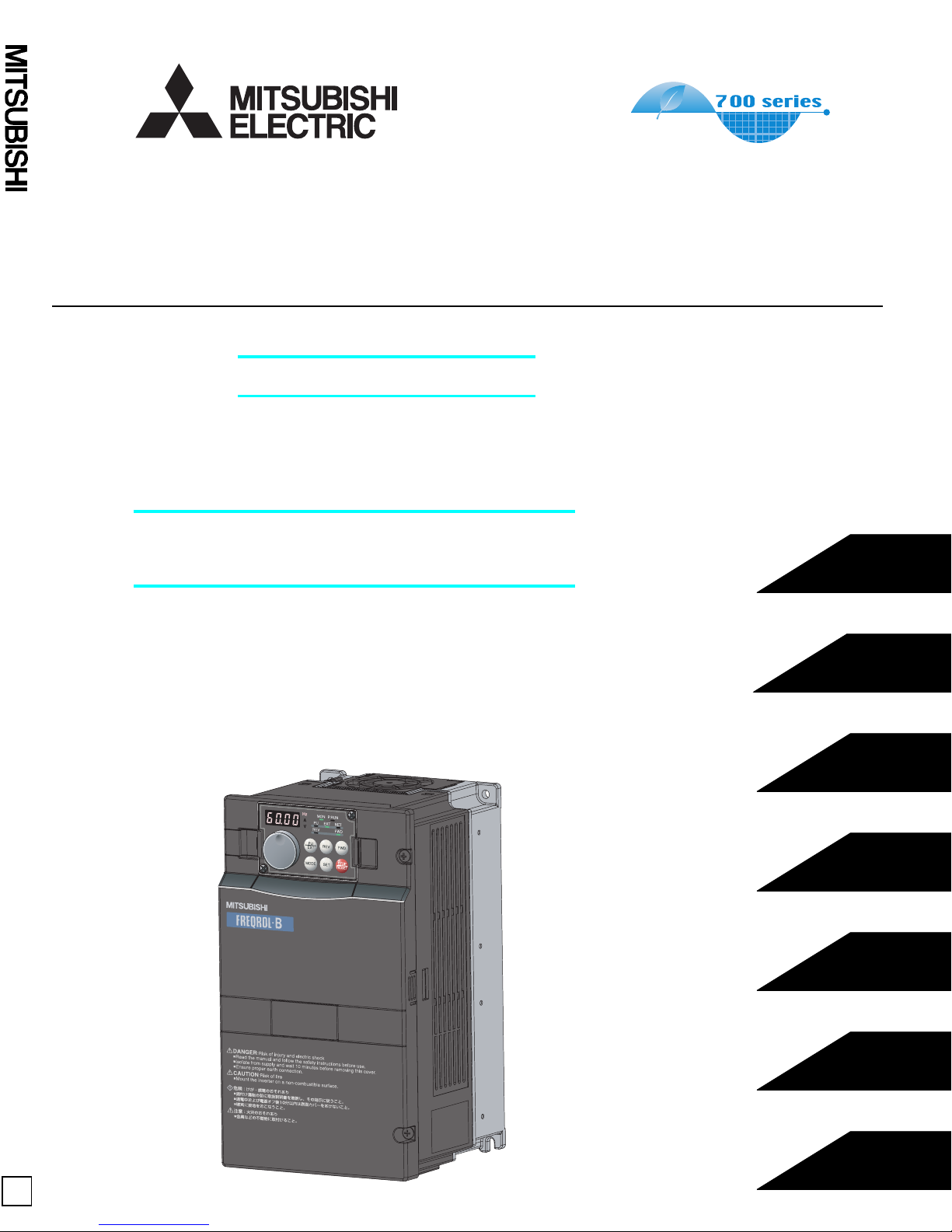
FR-B, B3
PRESSURE-RESISTANT, EXPLOSION-PROOF MOTOR DRIVING INVERTER
PRESSURE-RESISTANT, EXPLOSION-PROOF MOTOR DRIVING INVERTER
FR-B, B3
INSTRUCTION MANUAL (Applied)
(A700 SPECIFICATIONS)
Reduced torque type
FR-B-750 to 75K (200V CLASS)
FR-B-750 to 110K (400V CLASS)
Constant torque type
(Standard or low acoustic noise)
OUTLINE
1
FR-B3-(N)400 to 37K
FR-B3-(N)H400 to 37K
Be sure to perform offline auto tuning in the motor running
mode and operate with the advanced magnetic flux vector
control when using the FR-B3 series.
INSTRUCTION MANUAL (Applied)
WIRING
PRECAUTIONS FOR USE
OF THE INVERTER
PARAMETERS
PROTECTIVE FUNCTIONS
PRECAUTIONS FOR
MAINTENANCE AND INSPECTION
2
3
4
5
6
A
SPECIFICATIONS
7
Thank you for choosing this Mitsubishi Inverter.
This Instruction Manual (applied) provides instructions for advanced use of the FR-B, B3 series inverters.
Incorrect handling might cause an unexpected fault. Before using the inverter, always read this instruction manual and the instruction manual
(basic) [IB-0600271ENG] packed with the product carefully to use the equipment to its optimum.
This section is specifically about safety matters
Do not attempt to install, operate, maintain or inspect the inverter until you
have read through instruction manual (basic) and appended documents
carefully and can use the equipment correctly. Do not use the inverter until
you have a full knowledge of the equipment, safety information and
instructions. In this instruction manual, the safety instruction levels are
classified into "WARNING" and "CAUTION".
Assumes that incorrect handling may cause hazardous
conditions, resulting in death or severe injury.
Assumes that incorrect handling may cause
hazardous conditions, resulting in medium or slight
injury, or may cause physical damage only.
Note that even the level may lead to a serious consequence
according to conditions. Please follow strictly the instructions of both levels
because they are important to personnel safety.
1. Electric Shock Prevention
• While power is on or when the inverter is running, do not open the front cover.
Otherwise you may get an electric shock.
• Do not run the inverter with the front cover or wiring cover removed.
Otherwise, you may access the exposed high-voltage terminals or the charging
part of the circuitry and get an electric shock.
•
Even if power is off, do not remove the front cover except for wiring or periodic
inspection.You may access the charged inverter circuits and get an electric shock.
• Before starting wiring or inspection, check to make sure that the operation panel
indicator is off, wait for at least 10 minutes after the power supply has been
switched off, and check that there are no residual voltage using a tester or the
like. The capacitor is charged with high voltage for some time after power off and
it is dangerous.
WARNING
CAUTION
CAUTION
WARNING
(2) Wiring
• Do not install a power factor correction capacitor or surge suppressor/radio
noise filter (capacitor type filter) on the inverter output side.
• The connection orientation of the output cables U, V, W to the motor will affect
the direction of rotation of the motor.
(3) Test operation and adjustment
• For the FR-B3 series, operate with advanced magnetic flux vector control after
performing offline auto tuning.
• Before starting operation, confirm and adjust the parameters. A failure to do so
may cause some machines to make unexpected motions.
(4) Operation
• Since this inverter is used in combination with the Mitsubishi inverter-driven,
pressure-resistant, explosion-proof motor, note the driven motor used with the
inverter.
• Note that this inverter cannot be used with the Mitsubishi increased-safety,
explosion-proof motor.
• When you have chosen the retry function, stay away from the equipment as it
will restart suddenly after an alarm stop.
• The key is valid only when the appropriate function setting (refer to page
177 ) has been made. Prepare an emergency stop circuit (power off, mechanical
brake operation for an emergency stop, etc.) and switch separately.
• Make sure that the start signal is off before resetting the inverter alarm. A failure
to do so may restart the motor suddenly.
• The load used should be a three-phase induction motor only. Connection of any
other electrical equipment to the inverter output may damage the inverter as well as
equipment.
CAUTION
CAUTION
WARNING

1 OUTLINE 1
1.1 Product checking and parts identification ........................................................ 2
1.2 Inverter and peripheral devices.......................................................................... 3
1.2.1 Peripheral devices ..................................................................................................................... 4
1.3 Method of removal and reinstallation of the front cover..................................6
1.4 Installation of the inverter and enclosure design ............................................. 8
1.4.1 Inverter installation environment................................................................................................ 8
1.4.2 Cooling system types for inverter enclosure............................................................................ 10
1.4.3 Inverter placement................................................................................................................... 10
2 WIRING 13
CONTENTS

Content
3.1 Noise and leakage currents ..............................................................................40
3.1.1 Leakage currents and countermeasures ................................................................................. 40
3.1.2 Inverter-generated noises and their reduction techniques ...................................................... 42
3.1.3 Power supply harmonics ......................................................................................................... 44
3.1.4 Harmonic suppression guideline .............................................................................................45
3.2 Installation of a reactor ..................................................................................... 48
3.3 Power-off and magnetic contactor (MC).......................................................... 48
3.4 Precautions for use of the inverter ..................................................................49
4 PARAMETERS 51
4.1 Operation panel (FR-DU07) ...............................................................................52
4.1.1 Parts of the operation panel (FR-DU07) .................................................................................. 52

4.8.2 Starting frequency and start-time hold function (Pr. 13, Pr. 571) ........................................... 90
4.8.3 Acceleration/deceleration pattern (Pr. 29, Pr. 140 to Pr. 143, Pr. 380 to Pr. 383,
Pr. 516 to Pr. 519) .................................................................................................................. 91
4.8.4 Shortest acceleraiton/deceleration and optimum acceleration/deceleration
(automatic acceleration/deceleration) (Pr. 61 to Pr. 63, Pr. 292, Pr. 293) ............................. 94
4.9 Selection and protection of a motor ............................................................... 96
4.9.1 Motor protection from overheat (Electronic thermal relay function) (Pr. 9) ............................. 96
4.9.2 Applied motor (Pr. 71) ............................................................................................................ 99
4.10 Motor brake and stop operation .................................................................... 100
4.10.1 DC injection brake and zero speed control, servo lock (X13 signal, Pr. 10 to Pr. 12) .......... 100
4.10.2 Selection of regenerative brake (Pr. 30, Pr. 70) (75K or more) ............................................ 102
4.10.3 Stop selection (Pr. 250) ........................................................................................................ 104
4.10.4 Stop-on contact control function (Pr. 6, Pr. 48, Pr. 270, Pr. 275) ........................................ 105
4.10.5 Brake sequence function (Pr. 278 to Pr. 285, Pr. 292) ......................................................... 108

Content
4.14.1 Retry function (Pr. 65, Pr. 67 to Pr. 69) ................................................................................ 155
4.14.2 Alarm code output selection (Pr. 76) .................................................................................... 157
4.14.3 Input/output phase failure protection selection (Pr. 251, Pr. 872) ........................................ 158
4.14.4 Overspeed detection (Pr. 374) ............................................................................................. 158
4.14.5 Encoder signal loss detection (Pr. 376) ................................................................................ 158
4.14.6 Fault definition (Pr. 875) ....................................................................................................... 159
4.15 Energy saving operation and energy saving monitor ................................. 160
4.15.1 Energy saving monitor (Pr. 891 to Pr. 899) .......................................................................... 160
4.16 Frequency setting by analog input (terminal 1, 2, 4) ................................... 165
4.16.1 Function assignment of analog input terminal (Pr. 858, Pr. 868) ......................................... 165
4.16.2 Analog input selection (Pr. 73, Pr. 267) ................................................................................ 166
4.16.3 Analog input compensation (Pr. 73, Pr. 242, Pr. 243, Pr. 252, Pr. 253) ............................... 169
4.16.4 Response level of analog input and noise elimination (Pr. 74, Pr. 849) ............................... 171

4.20.4 Frequency setting by pulse train input (Pr. 291, Pr. 384 to Pr. 386)..................................... 239
4.20.5 Encoder feedback control (Pr. 144, Pr. 285, Pr. 359, Pr. 367 to Pr. 369) ........................... 242
4.20.6 Regeneration avoidance function (Pr. 665, Pr. 882 to Pr. 886) ............................................ 244
4.21 Useful functions.............................................................................................. 246
4.21.1 Cooling fan operation selection (Pr. 244) ............................................................................. 246
4.21.2 Display of the life of the inverter parts (Pr. 255 to Pr. 259)................................................... 247
4.21.3 Maintenance timer alarm (Pr. 503, Pr. 504) ......................................................................... 249
4.21.4 Current average value monitor signal (Pr. 555 to Pr. 557) ................................................... 250
4.21.5 Free parameter (Pr. 888, Pr. 889) ........................................................................................ 252
4.22 Setting of the parameter unit and operation panel...................................... 253
4.22.1 PU display language selection (Pr. 145) .............................................................................. 253
4.22.2 Operation panel frequency setting/key lock operation selection (Pr. 161) ........................... 253
4.22.3 Buzzer control (Pr. 990)........................................................................................................ 255

Content
5.5.9 Speed varies during operation............................................................................................... 280
5.5.10 Operation mode is not changed properly .............................................................................. 280
5.5.11 Operation panel (FR-DU07) display is not operating............................................................. 281
5.5.12 POWER lamp is not lit ........................................................................................................... 281
5.5.13 Parameter write cannot be performed ................................................................................... 281
6 PRECAUTIONS FOR MAINTENANCE AND INSPECTION 283
6.1 Inspection item................................................................................................. 284
6.1.1 Daily inspection ..................................................................................................................... 284
6.1.2 Periodic inspection ................................................................................................................ 284
6.1.3 Daily and periodic inspection................................................................................................. 285
6.1.4 Display of the life of the inverter parts ................................................................................... 286
6.1.5 Checking the inverter and converter modules ....................................................................... 286

APPENDICES 307
Appendix 1 For customers who have replaced the older model with this
inverter ................................................................................................ 308
Appendix 1-1 Replacement of the FR-B,B3 series (A500 specifications) ....................................... 308
Appendix 2 Control mode-based parameter (function) correspondence
table and instruction code list .......................................................... 310

1 OUTLINE
This chapter describes the basic "OUTLINE" for use of this
product.
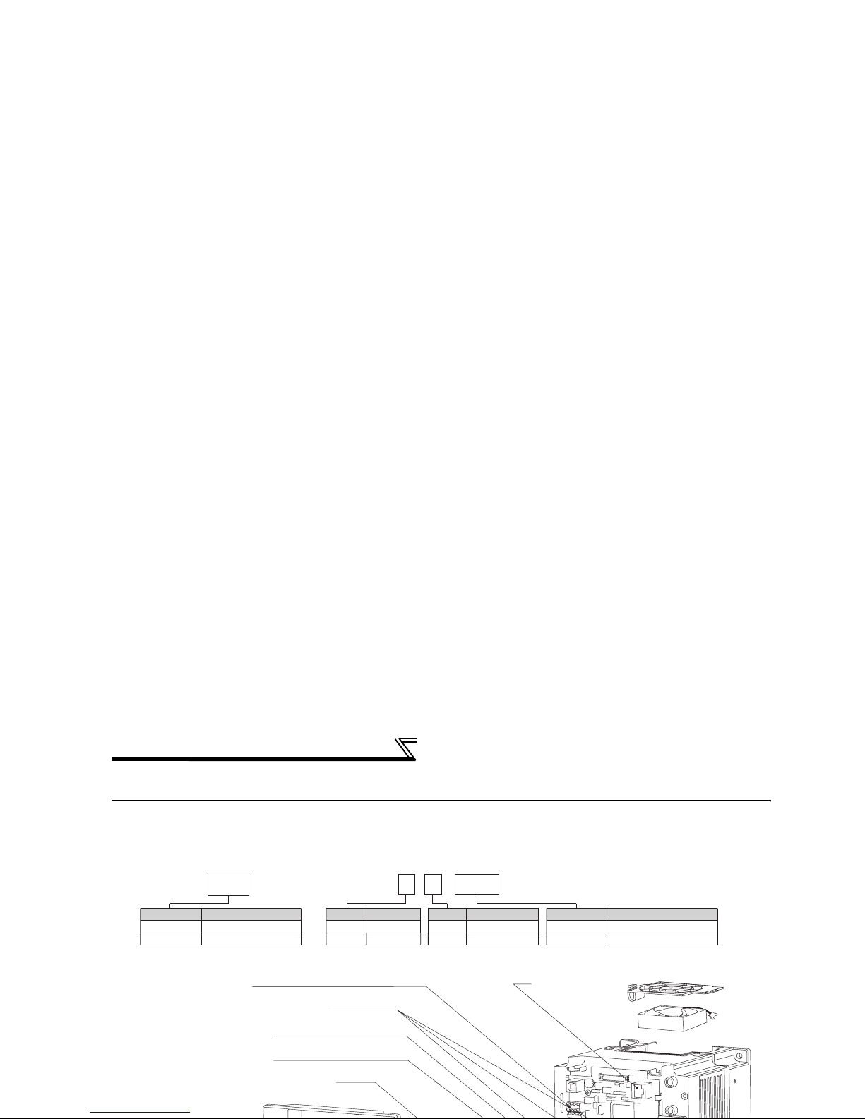
Product checking and parts identification
1.1 Product checking and parts identification
Unpack the inverter and check the capacity plate on the front cover and the rating plate on the inverter side face to
ensure that the product agrees with your order and the inverter is intact.
EMC filter ON/OFF connector
AU/PTC switchover switch
Cooling fan
PU connector
RS-485 terminals
Connector for plug-in option connection
(Refer to the instruction manual of options.)
Voltage/current input switch
FR
-B-750
Indicate capacity(kW)
Symbol
Inverter Capacity
Indicate capacity(W)
5.5K to 110K
750 to 3700
Indicate capacity(kW)
Symbol
Voltage Class
Indicate capacity(W)
5.5K to 37K
750 to 3700
FR B3-- -
750
N H
400V Class
Voltage Class
200V Class
H
None
Symbol
Low noise
Symbol
Noise
Standard
N
None
As the name of the FR-B series does not include a symbol indicating voltage
class, check the voltage class with the input rating on the rating plate.
· Inverter Type
(Refer to page 28)
(Refer to page 15)
(Refer to page 288)
(Refer to page 198)
(Refer to the Instruction Manual (applied).)
(Refer to page 14)
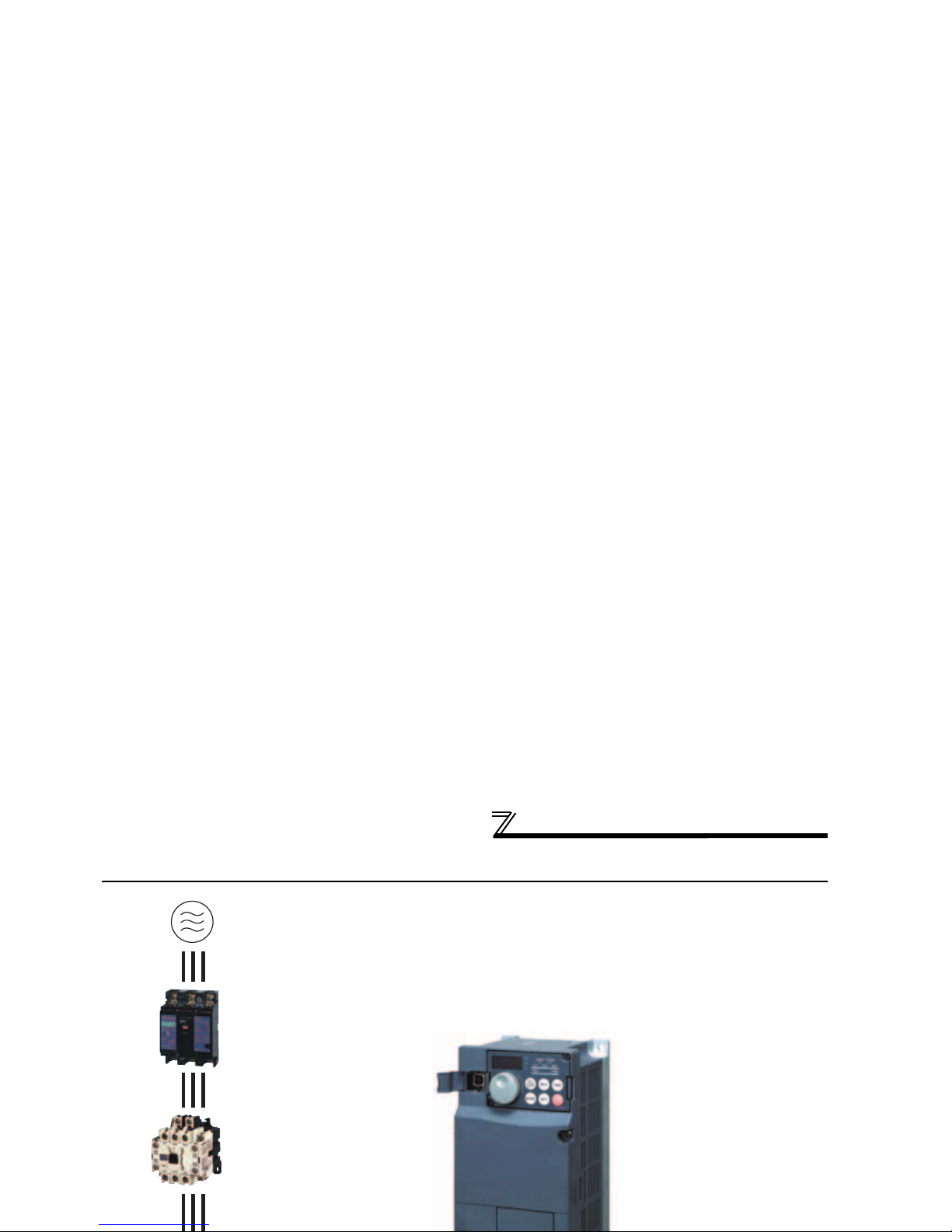
Inverter and peripheral devices
1.2 Inverter and peripheral devices
Three-phase AC power supply
Use within the permissible power supply
specifications of the inverter.
Moulded case circuit breaker (MCCB) or
earth leakage current breaker (ELB),
fuse
The breaker must be selected carefully
since an in-rush current flows in the inverter
at power on.
Magnetic contactor (MC)
Install the magnetic contactor to ensure
safety. Do not use this magnetic contactor
to start and stop the inverter. Doing so will
cause the inverter life to be shorten.
Reactor (FR-HAL, FR-HEL option)
Reactors (option) must be used when power
harmonics measures are taken, the power factor is
to be improved or the inverter is installed near a
(Refer to page 298)
(Refer to page 4)
(Refer to page 48)
Inverter (FR-B,B3)
The life of the inverter is influenced by
ambient temperature. The ambient
temperature should be as low as possible
within the permissible range. This must be
noted especially when the inverter is
installed in an enclosure. (Refer to page 8)
Wrong wiring might lead to damage of the
inverter. The control signal lines must be
kept fully away from the main circuit to
protect them from noise.(Refer to page 14)
Refer to page 15 for the built-in EMC filter.

Inverter and peripheral devices
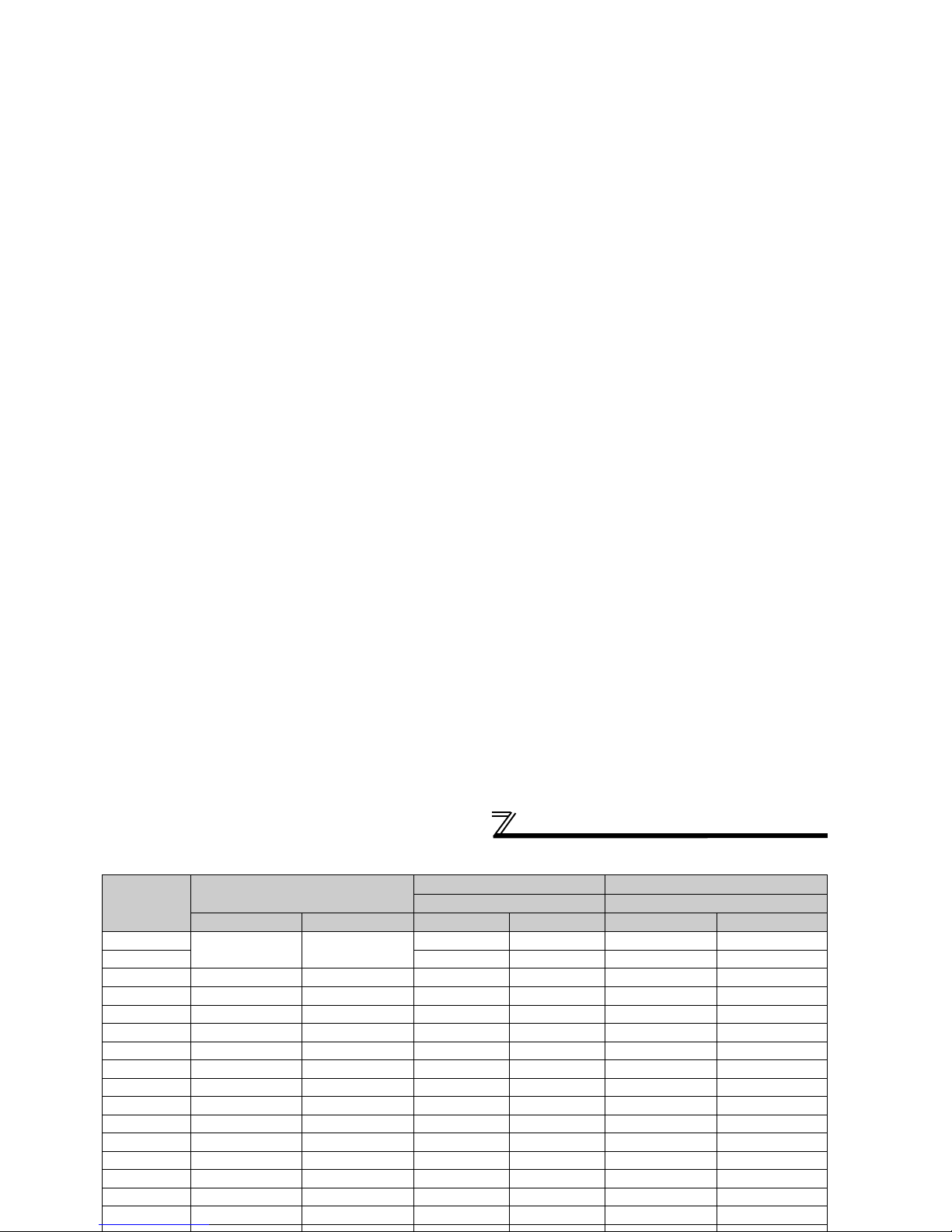
1.2.1 Peripheral devices
Check the motor capacity of the inverter you purchased. Appropriate peripheral devices must be selected according to
the capacity. Refer to the following list and prepare appropriate peripheral devices:
200V class
Motor Output
(kW)
*1
Applicable Inverter Type
Breaker Selection*2,4 Input Side Magnetic Contactor*3
Reactor connection Reactor connection
FR-B FR-B3
without with
without
with
0.4 FR-B-750 FR-B3-(N)400 30AF 5A 30AF 5A S-N10 S-N10
0.75 FR-B-750 FR-B3-(N)750 30AF 10A 30AF 10A S-N10 S-N10
1.5 FR-B-1500 FR-B3-(N)1500 30AF 15A 30AF 15A S-N10 S-N10
2.2 FR-B-2200 FR-B3-(N)2200 30AF 20A 30AF 15A S-N10 S-N10
3.7 FR-B-3700 FR-B3-(N)3700 30AF 30A 30AF 30A S-N20, N21 S-N10
5.5 FR-B-5.5K FR-B3-(N)5.5K 50AF 50A 50AF 40A S-N25 S-N20, N21
7.5 FR-B-7.5K FR-B3-(N)7.5K 100AF 60A 50AF 50A S-N25 S-N25
11 FR-B-11K FR-B3-(N)11K 100AF 75A 100AF 75A S-N35 S-N35
15 FR-B-15K FR-B3-(N)15K 225AF 125A 100AF 100A S-N50 S-N50
18.5 FR-B3-(N)18.5K 225AF 150A 225AF 125A S-N65 S-N50
22 FR-B-22K FR-B3-(N)22K 225AF 175A 225AF 150A S-N80 S-N65
30 FR-B-30K FR-B3-(N)30K 225AF 225A 225AF 175A S-N95 S-N80
Inverter and peripheral devices
400V class
Motor Output
(kW)
*1
Applicable Inverter Type
Breaker Selection*2,4 Input Side Magnetic Contactor*3
Reactor connection Reactor connection
FR-B FR-B3
without with
without
with
0.4
FR-B-750 FR-B3-(N)H400
30AF 5A 30AF 5A S-N10 S-N10
0.75 30AF 5A 30AF 5A S-N10 S-N10
1.5 FR-B-1500 FR-B3-(N)H1500 30AF 10A 30AF 10A S-N10 S-N10
2.2 FR-B-2200 FR-B3-(N)H2200 30AF 10A 30AF 10A S-N10 S-N10
3.7 FR-B-3700 FR-B3-(N)H3700 30AF 20A 30AF 15A S-N10 S-N10
5.5 FR-B-7.5K FR-B3-(N)H5.5K 30AF 30A 30AF 20A S-N20 S-N11, N12
7.5 FR-B-7.5K FR-B3-(N)H7.5K 30AF 30A 30AF 30A S-N20 S-N20
11 FR-B-15K FR-B3-(N)H11K 50AF 50A 50AF 40A S-N20 S-N20
15 FR-B-15K FR-B3-(N)H15K 100AF 60A 50AF 50A S-N25 S-N20
18.5 FR-B3-(N)H18.5K 100AF 75A 100AF 60A S-N25 S-N25
22 FR-B-22K FR-B3-(N)H22K 100AF 100A 100AF 75A S-N35 S-N25
30 FR-B-37K FR-B3-(N)H30K 225AF 125A 100AF 100A S-N50 S-N50
37 FR-B-37K FR-B3-(N)H37K 225AF 150A 225AF 125A S-N65 S-N50
45 FR-B-55K 225AF 175A 225AF 150A S-N80 S-N65
55 FR-B-55K 225AF 200A 225AF 175A S-N80 S-N80
75 FR-B-75K 225AF 225A S-N95
Method of removal and reinstallation of the
front cover
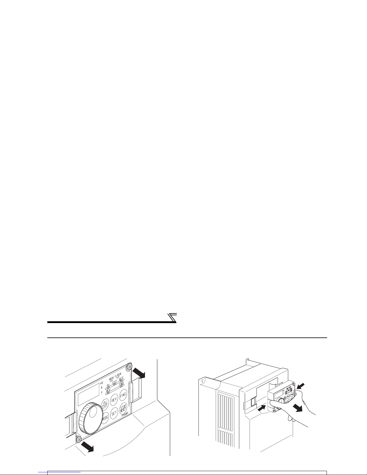
1.3 Method of removal and reinstallation of the front cover
•Removal of the operation panel
1) Loosen the two screws on the operation panel.
(These screws cannot be removed.)
2) Push the left and right hooks of the operation panel
and pull the operation panel toward you to remove.
When reinstalling the operation panel, insert it straight to reinstall securely and tighten the fixed screws of the
operation panel.
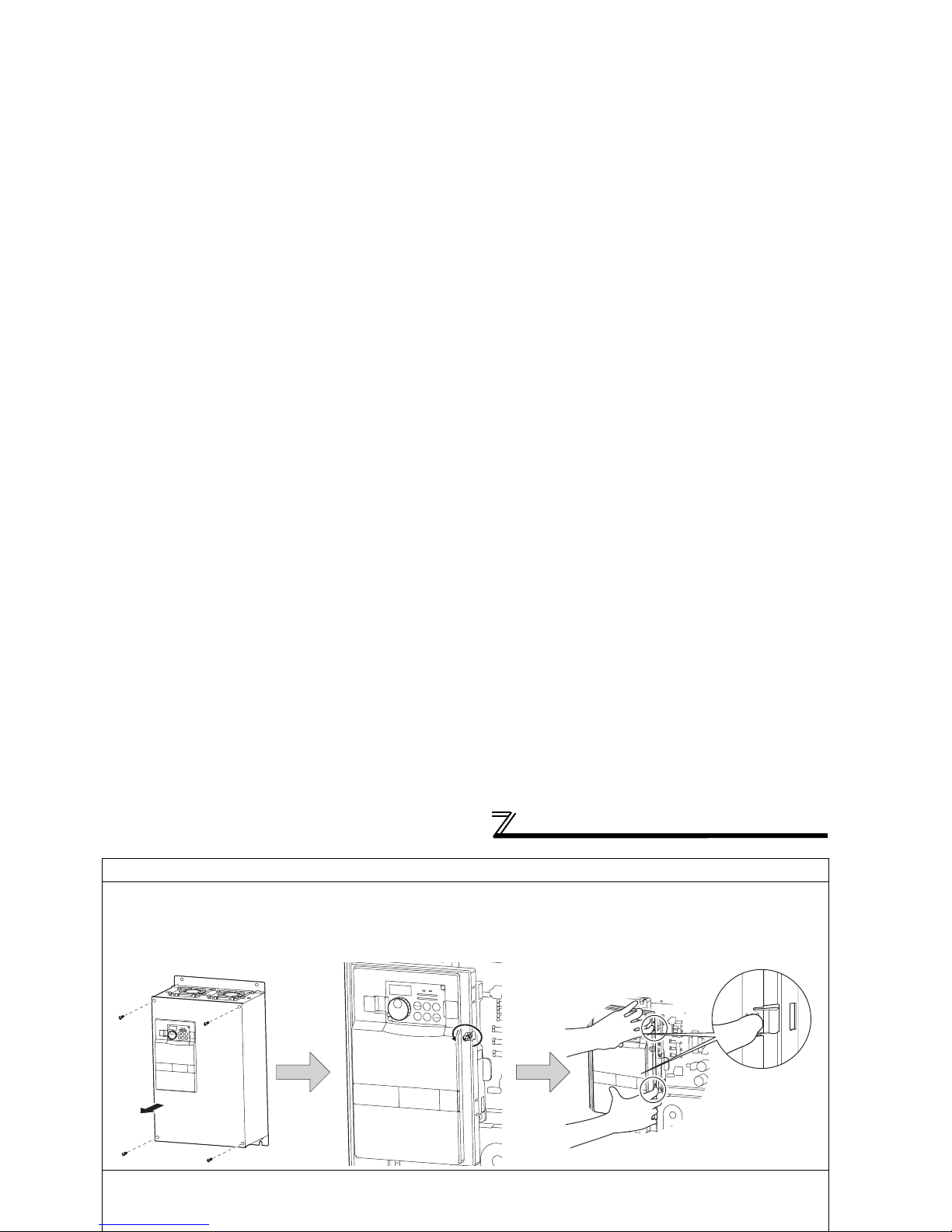
Method of removal and reinstallation of the
front cover
30K or more
•
Removal
•Reinstallation
Front cover 2
Front cover 1
Installation hook
1) Remove installation screws on
the front cover 1 to remove the
front cover 1.
2) Loosen the installation
screws of the front cover 2.
3) Pull the front cover 2 toward you to
remove by pushing an installation
hook on the right side using left
fixed hooks as supports.
1) Insert the two fixed hooks on the left side of the
front cover 2 into the sockets of the inverter.
2) Using the fixed hooks as supports, securely
press the front cover 2 against the inverter.

Installation of the inverter and enclosure
design
1.4 Installation of the inverter and enclosure design
When an inverter enclosure is to be designed and manufactured, heat generated by contained equipment, etc., the
environment of an operating place, and others must be fully considered to determine the enclosure structure, size and
equipment layout. The inverter unit uses many semiconductor devices. To ensure higher reliability and long period of
operation, operate the inverter in the ambient environment that completely satisfies the equipment specifications.
1.4.1 Inverter installation environment
As the inverter installation enviromnet should satisfiy the standard specifications indicated in the following table,
operation in any place that does not meet these conditions not only deteriorates the performance and life of the
inverter, but also causes a failure. Refer to the following points and take adequate measures.
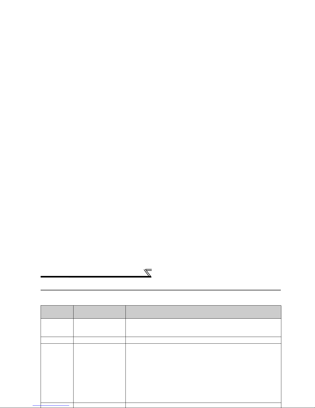
Environmental standard specifications of inverter
Item Description
Ambient temperature -10 to +50°C (non-freezing)
Ambient humidity 90% RH maximum (non-condensing)
Atmosphere Free from corrosive and explosive gases, dust and dirt
Maximum Altitude 1,000m or less
Vibration
5.9m/s
2
or less (JIS C 60068-2-6 compliant)

Installation of the inverter and enclosure
design
(3) Dust, dirt, oil mist
Dust and dirt will cause such faults as poor contact of contact points, reduced insulation or reduced cooling effect due
to moisture absorption of accumulated dust and dirt, and in-enclosure temperature rise due to clogged filter.
In the atmosphere where conductive powder floats, dust and dirt will cause such faults as malfunction, deteriorated
insulation and short circuit in a short time.
Since oil mist will cause similar conditions, it is necessary to take adequate measures.
Countermeasures
• Place in a totally enclosed enclosure.
Take measures if the in-enclosure temperature rises. (Refer to page 10.)
• Purge air.
Pump clean air from outside to make the in-enclosure pressure higher than the outside-air pressure.
(4) Corrosive gas, salt damage
If the inverter is exposed to corrosive gas or to salt near a beach, the printed board patterns and parts will corrode or
the relays and switches will result in poor contact.
In such places, take the measures given in Section (3).
(5) Explosive, flammable gases
As the inverter is non-explosion proof, it must be contained in an explosion proof enclosure.
Installation of the inverter and enclosure
design
1.4.2 Cooling system types for inverter enclosure
From the enclosure that contains the inverter, the heat of the inverter and other equipment (transformers, lamps,
resistors, etc.) and the incoming heat such as direct sunlight must be dissipated to keep the in-enclosure temperature
lower than the permissible temperatures of the in-enclosure equipment including the inverter.
The cooling systems are classified as follows in terms of the cooling calculation method.
1) Cooling by natural heat dissipation from the enclosure surface (Totally enclosed type)
2) Cooling by heat sink (Aluminum fin, etc.)
3) Cooling by ventilation (Forced ventilation type, pipe ventilation type)
4) Cooling by heat exchanger or cooler (Heat pipe, cooler, etc.)
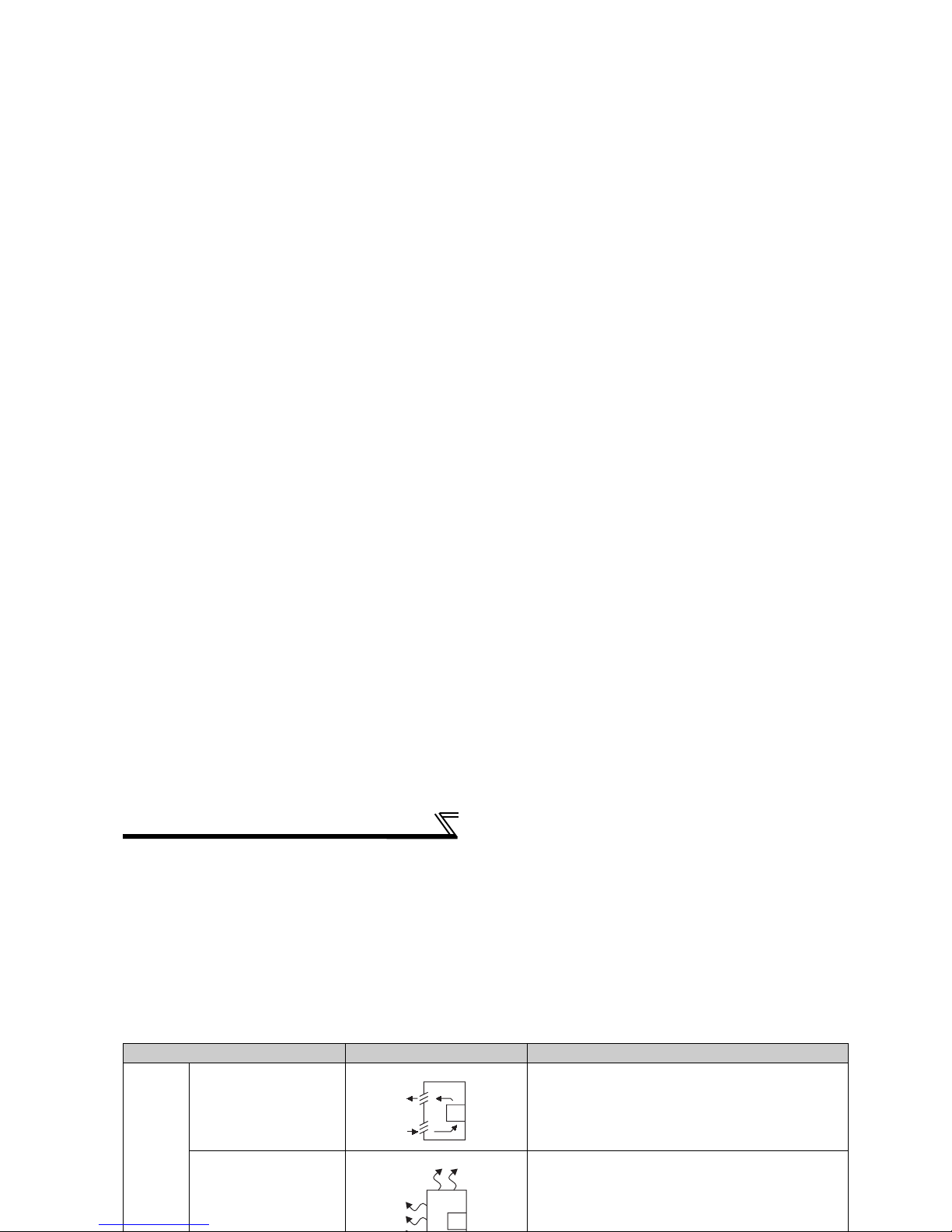
Cooling System Enclosure Structure Comment
Natural
cooling
Natural ventilation
(Enclosed, open type)
Low in cost and generally used, but the enclosure size
increases as the inverter capacity increases. For
relatively small capacities.
Natural ventilation (Totally
enclosed type)
Being a totally enclosed type, the most appropriate for
hostile environment having dust, dirt, oil mist, etc. The
enclosure size increases depending on the inverter
capacity.
INV
INV
Installation of the inverter and enclosure
design
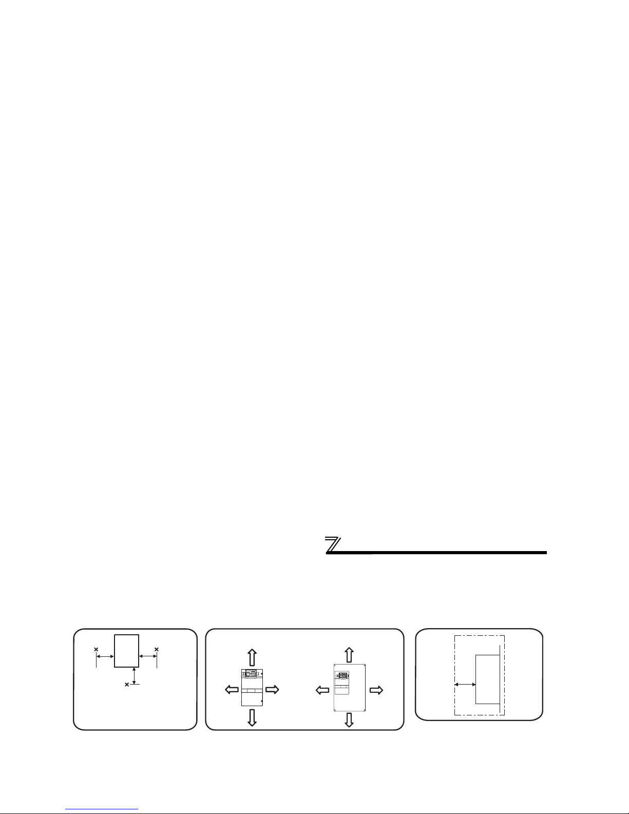
(2) Clearances around the inverter
To ensure ease of heat dissipation and maintenance, leave at least the shown clearances around the inverter. At least the
following clearances are required under the inverter as a wiring space, and above the inverter as a heat dissipation space.
(3) Inverter mounting orientation
Mount the inverter on a wall as specified. Do not mount it horizontally or any other way.
ClearancesAmbient temperature and humidity
Measurement
position
Measurement
position
Inverter
Leave enough clearances and take
cooling measures.
55K or less 75K or more
5cm
5cm
5cm
10cm or more
20cm or more
20cm or more
10cm or more
5cm
or more *
5cm
or more *
10cm
or more
10cm
or more
Temperature:
-10°C to 50°C
Ambient humidity:
90% RH maximum
(front)
*1cm or more for 3700 or less
Clearances (side)
Inverter
5cm
or more

MEMO

2 WIRING
This chapter describes the basic "WIRING" for use of this
product.
Wiring
2.1 Wiring
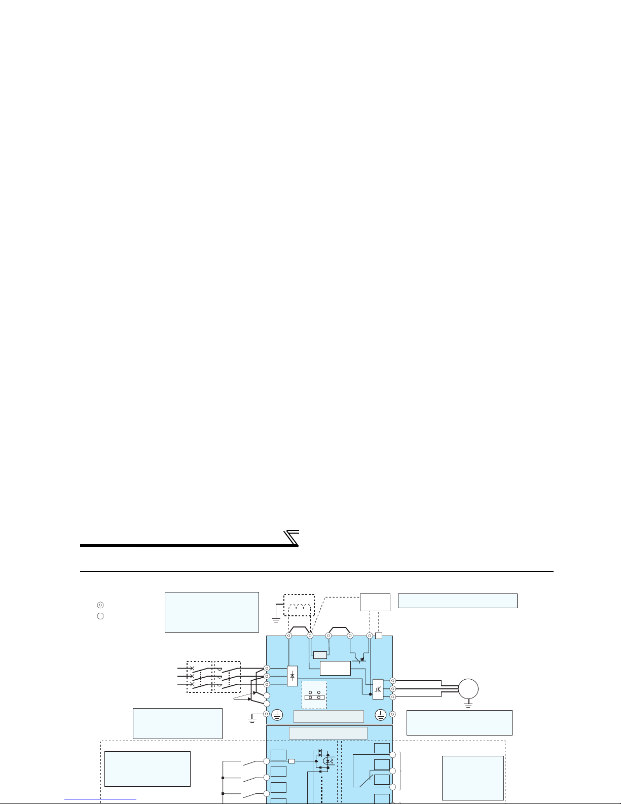
2.1.1 Terminal connection diagram
R/L1
S/L2
T/L3
R1/L11
S1/L21
Jumper
C1
B1
A1
U
V
W
P1
*1
*8
MC
Main circuit
Control circuit
C2
IM
STF
STR
STOP
ON
OFF
*2
Earth (Ground)
*8.The FR-B-750, FR-B3(N)450,750
are not provided with the EMC
filter ON/OFF connector. (Always on)
R
PX PR N/-P/+
Main circuit terminal
Control circuit terminal
Sink logic
Three-phase AC
power supply
MCCB
Jumper
Earth
(Ground)
EMC filter
ON/OFF
connecter
Earth
(Ground)
Control input signals (No voltage input allowed)
Forward
rotation
start
Reverse
rotation
start
Start self-
holding selection
Terminal functions vary with
the input terminal
assignment (Pr. 178 to Pr. 189)
Relay output 1
(Alarm output)
Terminal functions
vary with the output
terminal assignment
(Pr. 195, Pr. 196)
Relay output
*2. To supply power to the
control circuit separately,
remove the jumper across
R1/L11 and S1/L21.
Jumper
Explosion-proof
motor
Inrush current
limit circuit
*1. DC reactor (FR-HEL)
Be sure to connect the DC reactor
supplied with the 75K or more.
When a DC reactor is connected to
the 55K or less, remove the jumper
across P1-P/+.
Brake unit
(Option)
CN8
*7
Jumper
*7. A CN8 connector is provided with the 75K
or more.
(Refer to page 118)
(Refer to page 125)
Wiring
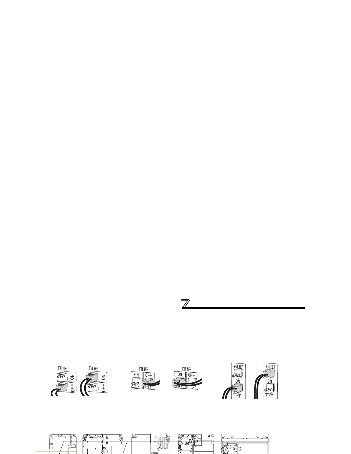
2.1.2 EMC filter
This inverter is equipped with a built-in EMC filter (capacitive filter) and common mode core.
The EMC filter is effective for reduction of air-propagated noise on the input side of the inverter.
The EMC filter is factory-set to disable (OFF). To enable it, fit the EMC filter ON/OFF connector to the ON position.
The input side zero-phase reactor, built-in the 55K or less inverter, is always valid regardless of on/off of the EMC filter
on/off connector.
EMC filter OFF EMC filter OFF EMC filter OFFEMC filter ON EMC filter ON EMC filter ON
(initial setting) (initial setting) (initial setting)
EMC filter
ON/OFF
connector
3700 or less
5.5K, 7.5K
11K or more
FR-B-1500 to 3700
(200V/400V class)
FR-B3-(N)(H)1500 to
3700
FR-B-5.5K, 7.5K
(200V class)
FR-B-7.5K (400V class)
FR-B3-(N)(H)5.5K, 7.5K
FR-B-11K(200V class)
FR-B-15K(400V class)
FR-B3-(N)11K
FR-B3-(N)H11K, 15k
FR-B-15K, 22K(200V class)
FR-B-22K(400V class)
FR-B3-(N)15k,22K
FR-B3-(N)H18.5k,22k
FR-B-30K or more (200V class)
FR-B-37K or more (400V class)
FR-B3-(N)(H) 30K or more
Main circuit terminal specifications
2.2 Main circuit terminal specifications
2.2.1 Specification of main circuit terminal
Term inal
Symbol
Terminal Name Description
R/L1,
S/L2,
T/L3
AC power input
Connect to the commercial power supply.
Keep these terminals open when using the high power factor converter
(MT-HC)
*1.
U, V, W Inverter output Connect a pressure-resistant, explosion-prrof motor.
R1/L11,
S1/L21
Power supply for
control circuit
Connected to the AC power supply terminals R/L1 and S/L2. To retain the
alarm display and alarm output or when using the high power factor
converter (
MT-HC
)*1, remove the jumpers from terminals R/L1-R1/L11 and
S/L2-S1/L21 and apply external power to these terminals.
Do not turn off the power supply for control circuit (R1/L11, S1/L21) with the
main circuit power (R/L1, S/L2, T/L3) on. Doing so may damage the
inverter. The circuit should be configured so that the main circuit power (R/
L1, S/L2, T/L3) is also turned off when the power supply for control circuit
(R1/L11, S1/L21) is off.
15K or less : 60VA, 18.5K or more : 80VA
P/+, PR 22K or less Keep these terminals open.
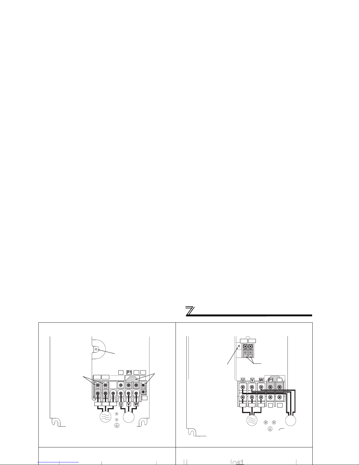
Main circuit terminal specifications
FR-B-5.5K, 7.5K
FR-B3-(N)5.5K, 7.5K
* Screw size of terminal R1/L11, S1/L21, PR, and PX is M4.
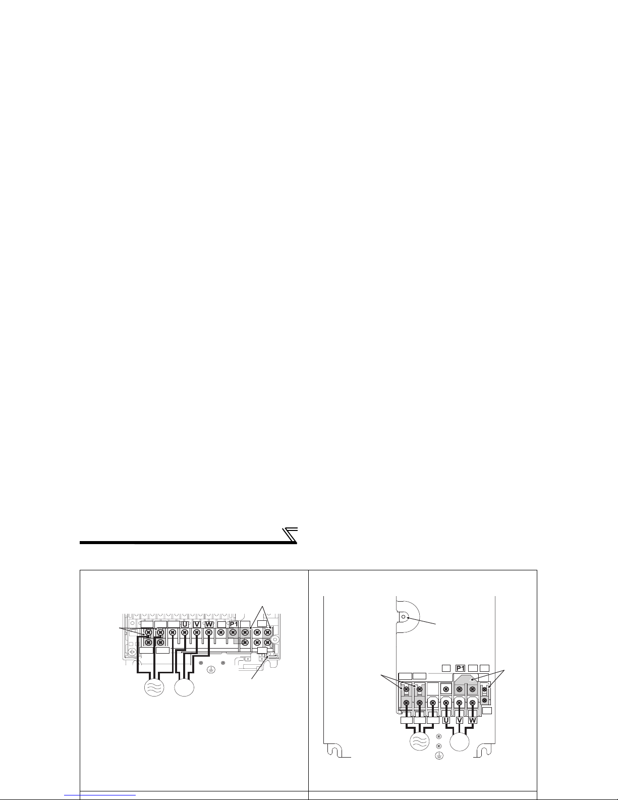
FR-B-11K
FR-B3-(N)11K
FR-B-15K, 22K
FR-B3-(N)15K, 18.5K, 22K
FR-B-30K, 37K, 45K
FR-B3-(N)30K, 37K
R/L1 S/L2 T/L3
N/-
P/+
PR
PX
R1/L11 S1/L21
IM
Screw size
(M5)
Screw size (M5)
Jumpe
r
Jumper
Charge lamp
Power supply
*
*
*
*
Explosionproof
motor
R1/L11 S1/L21
R/L1 S/L2 T/L3
N/-
P/+
PR
Charge lamp
Jumper
Jumper
Screw size
(M4)
Screw size (M5)
Screw size (M5)
Power supply
IM
Explosionproof
motor
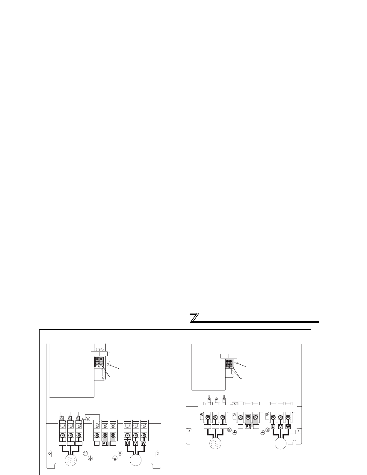
Main circuit terminal specifications
400V class
FR-B-750 to 3700
FR-B3-(N)H400 to 3700
FR-B-7.5K
FR-B3-(N)H5.5K 7.5K
FR-B-15K
FR-B-22K
R/L1 S/L2 T/L3
N/-
P/+
PR
PX
R1/L11 S1/L21
IM
Charge lamp
Jumper
Screw size (M4)
Screw size
(M4)
Jumper
Power
supply
Explosion-proof
motor
R/L1 S/L2 T/L3
N/-
P/+
PR
PX
R1/L11 S1/L21
IM
Screw size
(M4)
Screw size
(M4)
Jumper
Jumpe
r
Charge lamp
Power supply
Explosionproof
motor
Main circuit terminal specifications
FR-B-37K
FR-B3-(N)H30K, 37K
FR-B-55K
IM
Jumper
Jumper
Charge lamp
Screw size(M4)
Power
supply
R/L1 S/L2 T/L3
N/-
P/+
R1/L11 S1/L21
Explosionproof
Screw size
(30K: M6, 37K/45K: M8)
Screw size (30K: M6, 37K/45K: M8)
IM
Jumper
Jumper
Charge lamp
Screw size (M4)
Power
supply
R/L1 S/L2 T/L3
N/-
P/+
R1/L11 S1/L21
Screw size (M8) Screw size (M10) Screw size (M8)
Screw size (M8)
Explosionproof motor

Main circuit terminal specifications
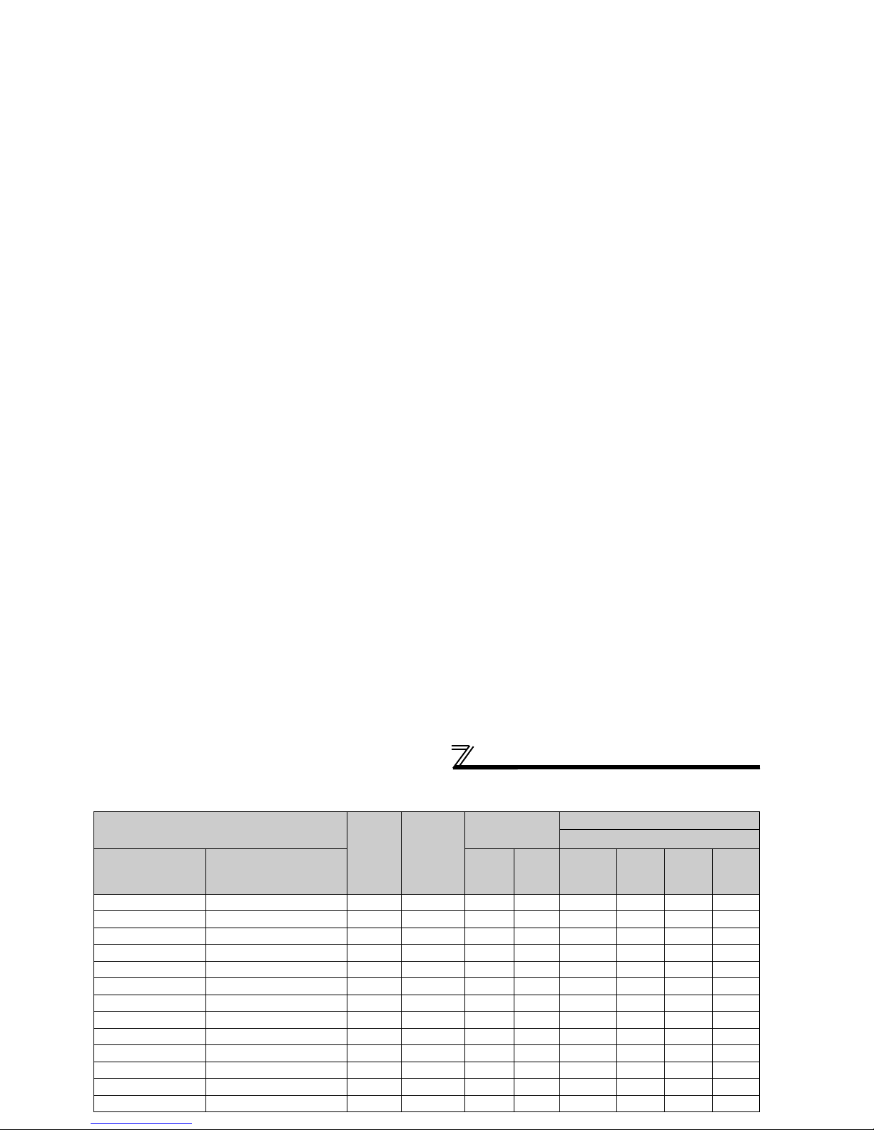
2.2.3 Cables and wiring length
(1) Applied cable size
Select the recommended cable size to ensure that a voltage drop will be 2% max.
If the wiring distance is long between the inverter and motor, a main circuit cable voltage drop will cause the motor
torque to decrease especially at the output of a low frequency.
The following table indicates a selection example for the wiring length of 20m.
200V class (when input power supply is 220V)
Applicable Inverter Type
Ter mi nal
Screw
Size
*2
Tightening
Tor que N· m
Crimping
Ter mina l
Cable Sizes
HIV, etc. (mm2) *1
R/L1,
S/L2,
T/L3
U, V, W
R/L1,
S/L2,
T/L3
U, V, W P/+, P1
Earth
(Ground)
cable
FR-B FR-B3
FR-B-750 to 2200 FR-B3-(N)400 to 2200 M4 1.5 2-4 2-4 2 2 2 2
FR-B-3700 FR-B3-(N)3700 M4 1.5 5.5-4 5.5-4 3.5 3.5 3.5 3.5
FR-B-5.5K FR-B3-(N)5.5K M4-M5 2.5 5.5-5 5.5-5 5.5 5.5 5.5 5.5
FR-B-7.5K FR-B3-(N)7.5K M4-M5 2.5 14-5 8-5 14 8 14 14
FR-B-11K FR-B3-(N)11K M5 2.5 14-5 14-5 14 14 14 14
FR-B-15K FR-B3-(N)15K M6 4.4 22-6 22-6 22 22 22 14
- FR-B3-(N)18.5K M8-M6 7.8 38-8 38-8 38 38 38 22
FR-B-22K FR-B3-(N)22K M8-M6 7.8 38-8 38-8 38 38 38 22
Main circuit terminal specifications
400V class (when input power supply is 440V)
Applicable Inverter Type
Ter mi nal
Screw
Size
*2
Tightening
Tor que N·m
Crimping
Ter mina l
Cable Sizes
HIV, etc. (mm2) *1
FR-B FR-B3
R/L1,
S/L2,
T/L3
U, V, W
R/L1,
S/L2,
T/L3
U, V, W P/+, P1
Earth
(Ground)
Cable
FR-B-750 to 3700 FR-B3-(N)H400 to 3700 M4 1.5 2-4 2-4 2 2 2 2
- FR-B3-(N)H5.5K M4 1.5 2-4 2-4 2 2 3.5 3.5
FR-B-7.5K FR-B3-(N)H7.5K M4 1.5 5.5-4 5.5-4 3.5 3.5 3.5 3.5
- FR-B3-(N)H11K M5 2.5 5.5-5 5.5-5 5.5 5.5 5.5 8
FR-B-15K FR-B3-(N)H15K M5 2.5 8-5 8-5 8 8 8 8
- FR-B3-(N)H18.5K M6 4.4 14-6 8-6 14 8 14 14
FR-B-22K FR-B3-(N)H22K M6 4.4 14-6 14-6 14 14 22 14
- FR-B3-(N)H30K M6 4.4 22-6 22-6 22 22 22 14
FR-B-37K FR-B3-(N)H37K M8 7.8 22-8 22-8 22 22 22 14
FR-B-55K - M8 7.8 60-8 60-8 60 60 60 22
FR-B-75K - M10 14.7 60-10 60-10 60 60 60 38
FR-B-90K - M10 14.7 60-10 60-10 60 60 80 38
FR-B-110K - M10-M12 14.7 80-10 80-10 80 80 80 38
*1 For the
55K
or less, the cable size is that of the cable (HIV cable (600V class 2 vinyl-insulated cable) etc.) with continuous maximum permissible
 Loading...