

Mitsubishi FR-AF840-00770, FR-AF820-01540, FR-AF820-04750, FR-AF860-00680, FR-AF860-04420 Installation Manualline
...
INVERTER
FR-AF800
INSTALLATION GUIDELINE
FR-AF820-01540 to 04750
FR-AF840-00770 to 06830
FR-AF842-07700 to 12120
FR-AF860-00680 to 04420
FR-AF862-05450 to 08500
Thank you for choosing this Mitsubishi inverter base unit.
This Installation Guideline provides handling information and precautions for use of this product. Incorrect
handling might cause an unexpected fault. Before using this product, always read this Installation Guideline
carefully to use this product correctly.
In addition, carefully read the Instruction Manual (Startup) enclosed with the separate control circuit board. Do not
use this product until you have a full knowledge of the product, safety information, and instructions.
Please forward this Installation Guideline to the end user.
CONTENTS
1. Introduction ........................................................ 2
2. Outline ................................................................ 2
3. Product Check .................................................... 3
4. Setting Up........................................................... 8
5. Operation check for the safety stop function . 14
800
1 Introduction
POINTPOINT
Thank you for choosing this Mitsubishi Inverter base unit.
This Installation Guideline explains how to set up an inverter base unit and a separately
sold control circuit board.
Read this Installation Guideline carefully to use this product correctly.
Please forward this Installation Guideline to the end user.
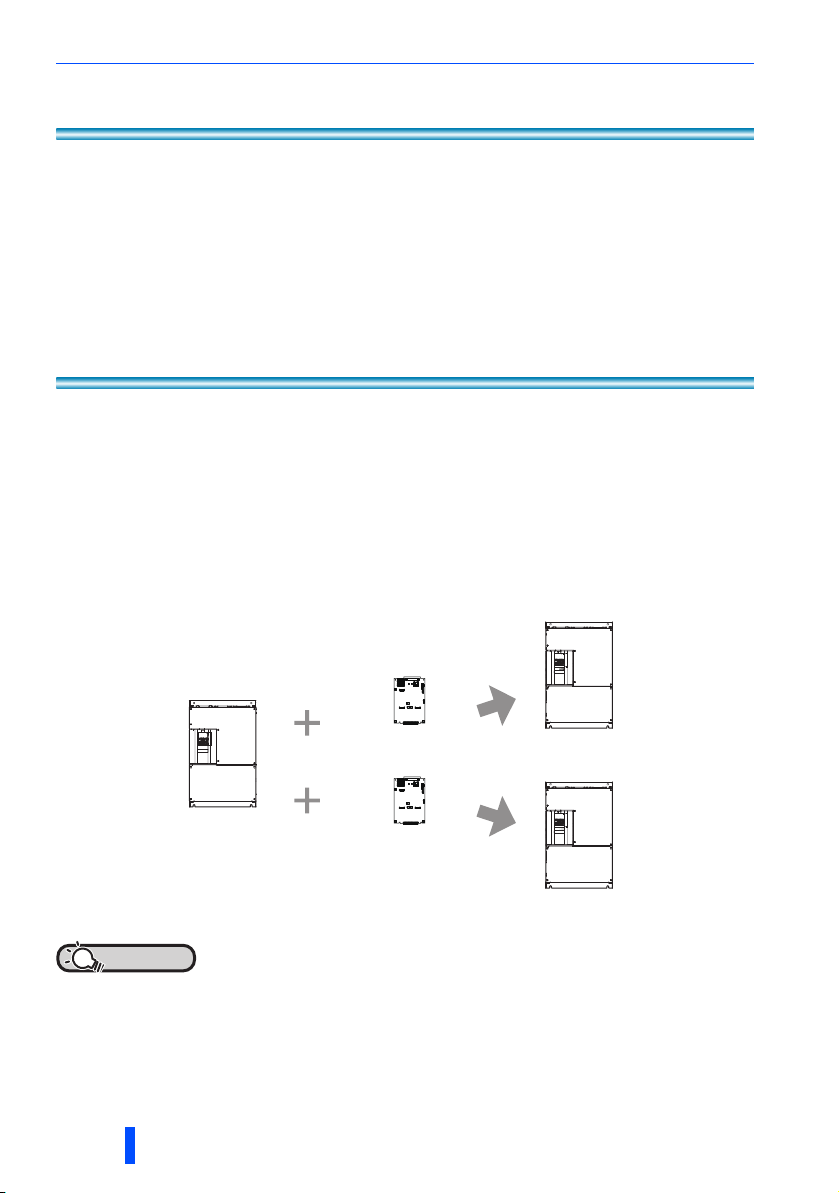
2 Outline
The FR-AF800 is a base unit of the inverter.
A base unit is a main circuit section of the inverter, where three-phase AC power is
converted to DC power and then converted to any three-phase AC power.
A control circuit board is a control circuit section which controls the inverter.
A base unit alone cannot be operated.
By combining the base unit and a separately sold control circuit board, they function as
an inverter.
Base unit
FR-AF840
• The product made up of a base unit and a control circuit board complies with
UL and EC directives (CE mark).
• If a combination of the base unit and control circuit board is not correct, an
inverter fault (E.PE2) occurs, disabling the inverter operation.
2 Introduction
Control circuit board
FR-CA80
Control circuit board
FR-CF80
Inverter
FR-A840
Inverter
FR-F840
3 Product Check
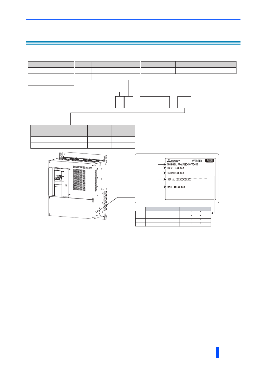
Base unit
Symbol Voltage class
2
4
200 V class
400 V class
600 V class6
Symbol Structure, functionality
Standard model0
Separated converter type
2
Symbol Description
00770 to 12120
Inverter SLD rated current (A)
Symbol
60
U6
F R - AF 8 2 0 -
Circuit board
coating
With
With With
Plated
conductor
Without Without
Without
CN8
connector
00770
Rating plate
Inverter model
Input rating
Output rating
SERIAL
Country of origin
Overload Current Rating Ambient Temperature
SLD 110% 60s, 120% 3s 40 C (104 F)
LD 120% 60s, 150% 3s 50 C (122 F)
ND 150% 60s, 200% 3s 50 C (122 F)
HD 200% 60s, 250% 3s 50 C (122 F)
- 60
Accessory
• Installation guideline (this guideline)
• For the FR-AF8[]-[]-U6, BCN-C22005-721 and BCN-C22005-742 (Instruction Manual
Supplement) are enclosed.
Product Check 3
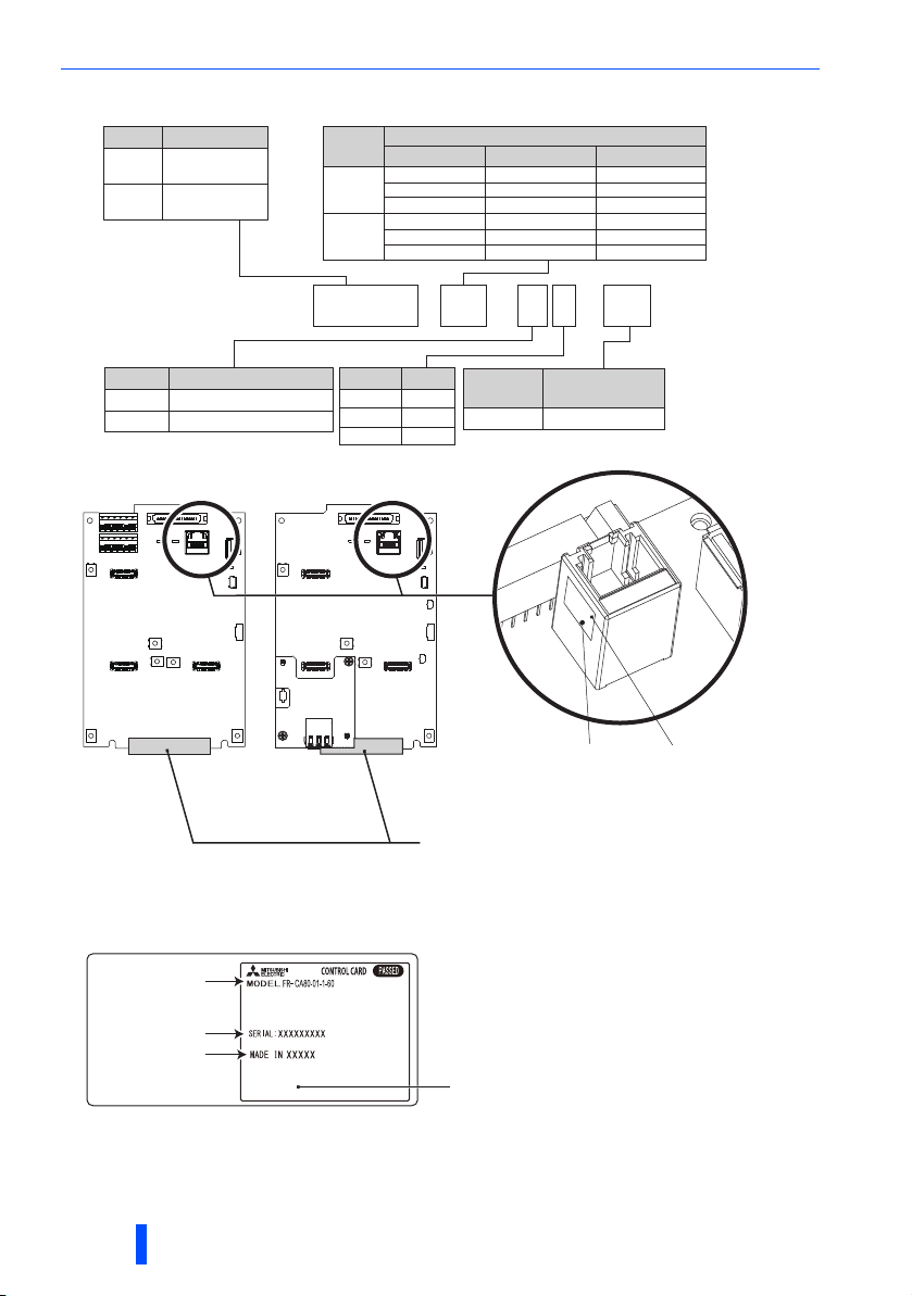
Control circuit board accessory
Symbol Description
Control unit for
CA80
FR-A800
Control unit for
CF80
FR-F800
Symbol
02
Compatible base unit
Voltage class FR-CA80
200 01540 to 03160 01540 to 04750
40001
600
200 03800, 04750
400
600
FR-CF80
00770 to 01800 00770 to 12120
00680, 01080
02160 to 12120
01440 to 08500
00680 to 08500
-
-
-
F R - CA80 - 01 -
Symbol Communication type
RS-485 communicationNone
E
RS-485 communication
type
Rating plate
Control circuit
board model
Ethernet
Symbol Type
1FM
2 CA
3 CA3
Ethernet type
E 1
- 60
Symbol
Circuit board
coating
With60
XXXXXXXXXXX
CA80-01-1
Control circuit
board model
SERIAL
Sponge for connector pin protection
Remove a sponge for connector pin
protection before installing the control unit to
the base unit.
Use care not to bend pins of the connector.
SERIAL
Country of origin
4 Product Check
Rating plate of the control circuit board
The rating plate is placed on the plastic bag.
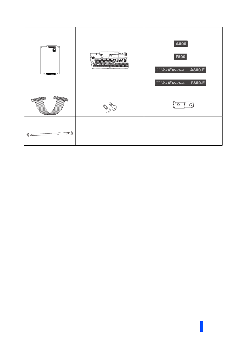
control circuit board 1 Control circuit terminal block 1 Sticker .....................1
FR-CF80-[]-[]-60
FR-CA80-[]-[]-60
FR-CF80-[]-E[]-60
FR-CA80-[]-E[]-60
Cable ...................... 1 Mounting screw (M3 × 6mm)
..........................2(3
)
Earth plate.............1
Earth cable ........... 1 Instruction Manual .............1 CD......................... 1
For the FR-CA80-[]-E[]-[] and the FR-CF80-[]-E[]-[], three mounting screws are supplied.
For the FR-CA80-[]-E[]-[] and the FR-CF80-[]-E[]-[], this accessory is supplied.
For the Instruction Manual and CD related to the inverter model in combination with the base
unit and the control circuit board, refer to page 6.
Product Check 5

Inverter model
as a result of
combination
SLD rated
current
Base unit
model
Control
circuit board
model
Reference manual
CD-ROM
Manual name
Manual
number
FR-A820-[]-1-60 01540 to 03160 FR-AF820-[]-60 FR-CA80-01-1-60
A800 INSTRUCTION MANUAL
(STARTUP)
IB-0600493
BKO-CA2250
FR-A820-[]-1-U6 03800, 04750 FR-AF820-[]-U6 FR-CA80- 02-1-60
FR-A840-[]-1-60 00770 to 01800 FR-AF840-[]-60 FR-CA80-01-1-60
FR-A840-[]-1-U6 02160 to 06830 FR-AF840-[]-U6 FR-CA80-02-1-60
FR-A840-[]-2-60
00770 to 01800
FR-AF840-[]-60
FR-CA80-01-2-60
02160 to 06830 FR-CA80-02-2-60
FR-A842-[]-1-U6
07700 to 12120
FR-AF842-[]-U6 FR-CA80-02-1-60 FR-A802
(SEPARATED CONVERTER TYPE)
INSTRUCTION MANUAL (HARDWARE)
IB-0600534ENG
FR-A842-[]-2-60 FR-AF842-[]-60 FR-CA80-02-2-60
FR-A860-[]-1-60
00680, 01080
FR-AF860-[]-60
FR-CA80-01-1-60 FR-A860 (600V CLASS SPECIFICATION
INVERTER)
INSTRUCTION MANUAL (STARTUP)
IB-0600562ENG
BKO-CA2378
01440 to 04420 FR-CA80-02-1-60
FR-A862-[]-1-60 05450 to 08500 FR-AF862-[]-60 FR-CA80-02-1-60
FR-A862
(SEPARATED CONVERTER TYPE)
INSTRUCTION MANUAL (HARDWARE)
IB-0600571ENG
FR-A820-[]-E1-60 01540 to 03160 FR-AF820-[]-60 FR-CA80-01-E1-60
A800-E INSTRUCTION MANUAL
(STARTUP)
IB-0600626
BKO-CA2486
FR-A820-[]-E1-U6 03800, 04750 FR-AF820-[]-U6 FR-CA80-02-E1-60
FR-A840-[]-E1-60 00770 to 01800 FR-AF840-[]-60 FR-CA80-01-E1-60
FR-A840-[]-E1-U6 02160 to 06830 FR-AF840-[]-U6 FR-CA80-02-E1-60
FR-A840-[]-E2-60
00770 to 01800
FR-AF840-[]-60
FR-CA80-01-E2-60
02160 to 06830 FR-CA80-02-E2-60
FR-A842-[]-E1-U6
07700 to 12120
FR-AF842-[]-U6 FR-CA80-02-E1-60 FR-A802-E
(SEPARATED CONVERTER TYPE)
INSTRUCTION MANUAL (HARDWARE)
IB-0600631ENG
FR-A842-[]-E2-60 FR-AF842-[]-60 FR-CA80-02-E2-60
FR-A860-[]-E1-60
00680, 01080
FR-AF860-[]-60
FR-CA80-01-E1-60 FR-A860-E (600V CLASS
SPECIFICATION INVERTER)
INSTRUCTION MANUAL (STARTUP)
IB-0600638ENG
BKO-CA2492
01440 to 04420 FR-CA80-02-E1-60
FR-A862-[]-E1-60 05450 to 08500 FR-AF862-[]-60 FR-CA80-02-E1-60
FR-A862-E
(SEPARATED CONVERTER TYPE)
INSTRUCTION MANUAL (HARDWARE)
IB-0600639ENG
Combination of the inverter and the Instruction Manual
The Instruction Manual and CD related to the inverter model in combination with the
base unit and the control circuit board are shown below.
6 Product Check
 Loading...