

Mitsubishi 7011A Technical Manual

MITSUBISHI
UNINTERRUPTIBLE POWER SUPPLY
7011A SERIES UPS
SINGLE PHASE PRODUCT
6kVA
8kVA
10kVA
12kVA
OWNERS / TECHNICAL MANUAL
OWNERS / TECHNICAL MANUAL
OWNERS / TECHNICAL MANUALOWNERS / TECHNICAL MANUAL
Revision 6.5: Jan. 24, 2003
ALN-H0379

MITSUBISHI
ELECTRIC
7011A SERIES UPS
OWNERS / TECHNICAL MANUAL
Preface
Page Number:
i
MITSUBISHI ELECTRIC 7011A SERIES UPS

MITSUBISHI
ELECTRIC
7011A SERIES UPS
OWNERS / TECHNICAL MANUAL
Page Number:
TABLE OF CO NTENTS
LIST OF TABLES ................................................................................................. iii
LIST OF FIGURES ............................................................................................... iv
HOW TO USE THIS MANUAL ............................................................................. v
SAFETY PRECAUTIONS HOW TO USE THIS MANUAL ................................... vi
1.0 INTRODUCTION ........................................................................................... 1-1
1.1 GENERAL....................................................................................................... 1-3
1.2 DEFINITIONS ................................................................................................ 1-4
1.3 OVERVIEW ................................................................................................... 1-5
1.4 SPECIFICATIONS ......................................................................................... 1-12
2.0 OPERAT O R CONTROLS A ND I NDICATORS ............................................ 2-1
2.1 STATUS INDICATORS .................................................................................. 2-2
ii
2.2 LCD DISPLAY ............................................................................................... 2-4
2.3 RS232C CONNECTOR (External communication connector)....................... 2-7
2.4 D-SUB 25 PIN CONNECTOR ....................................................................... 2-8
2.5 EXTERNAL SIGNAL TERMINAL BLOCK ..................................................... 2-9
3.0 INSTALLATION AND OPERATION ............................................................. 3-1
3.1 TRANSPORTATION AND INSTALLATION ................................................. 3-1
3.2 INSTALLATION PROCEDURE .................................................................... 3-1
3.3 PROCEDURE FOR CABLE CONNECTION................................................. 3-2
3.4 INSTALLATION PROCEDURE FOR BATTERY .......................................... 3-9
3.5 OPERATING PROCEDURES ...................................................................... 3-12
3.6 MAINTENANCE BYPASS SET-UP PROCEDURES ................................... 3-14
3.7 EXTERNAL BATTERY SET-UP PROCEDURES ........................................ 3-15
4.0 RESPONSE TO UPS FAILURE .................................................................... 4-1
5.0 PARTS REPLACEMENT .............................................................................. 5-1
6.0 FAULT CODES ............................................................................................. 6-1
7.0 WARRANTY & OUT OF WARRANTY SERVICE......................................... 7-1
MITSUBISHI ELECTRIC 7011A SERIES UPS

MITSUBISHI
ELECTRIC
7011A SERIES UPS
OWNERS / TECHNICAL MANUAL
Page Number:
List of Tables
Table 1.1 Power Specifications..................................................................... 1-12
Table 1.2 UPS Module Information............................................................... 1-12
Table 1.3 Rating of Conductor and Fuses.................................................... 1-12
Table 1.4 Detail of Specifications.................................................................. 1-13
Table 2.1 D-Sub 25 Pin connector................................................................ 2-9
Table 3.1 List of UPS Weights (lb.)............................................................... 3-1
Table 3.2 Recommended Cable S iz e and Torque Requirements................ 3-3
Table 3.3 Crimp Type Compression Lug ...................................................... 3-3
Table 3.4 Type and Number of Battery......................................................... 3-9
Table 6.1 Failure Code List........................................................................... 6-2
iii
MITSUBISHI ELECTRIC 7011A SERIES UPS

MITSUBISHI
ELECTRIC
7011A SERIES UPS
OWNERS / TECHNICAL MANUAL
Page Number:
List of Figures
Figure 1.1 Single Line Diagram-Normal Operation........................................ 1-5
Figure 1.2 Single Line Diagram-Bypass Operation........................................ 1-6
Figure 1.3 Single Line Diagram-Battery Operation........................................ 1-7
Figure 1.4 Singl e Li ne D iagram - UPS on Maintenance Bypass Operation.. 1-7
Figure 1.5 UPS Parts Location (6kVA)........................................................... 1-8
Figure 1.6 UPS Parts Location (8,10,12kVA)................................................. 1-9
Figure 1.7 UPS Parts Location (Rear view)................................................... 1-10
Figure 1.8 External I/F PCB RYER-A ............................................................ 1-10
Figure 2.1 Operation / Display Panel ............................................................ 2-1
Figure 2.2 LCD Display During Normal Operation ........................................ 2-2
Figure 2.3 Tree Diagram of LCD display (Top Page) ................................... 2-4
iv
Figure 2.4 Tree Diagram of LCD display (Normal Mode) ............................. 2-5
Figure 2.5 Tree Diagram of LCD display (User Setup Mode) ....................... 2-6
Figure 2.6 Tree Diagram of LCD display (Start Mode) ................................. 2-6
Figure 2.7 Tree Diagram of LCD display (Stop Mode) .................................. 2-6
Figure 2.8 Tree Diagram of LCD display (Stop Mode) .................................. 2-7
Figure 2.9 RS-232C Connectors ................................................................... 2-8
Figure 2.10 D-sub 25 Pin Connector ............................................................... 2-9
Figure 2.11 External Signal Terminal Block (NEC Class2).............................. 2-10
Figure 2.12 Control Wiring for External Contacts ............................................ 2-11
Figure 2.13 Remote “Startup” Contact Connections........................................ 2-12
Figure 3.1 Handling ....................................................................................... 3-1
Figure 3.2 Clearance for Ventilation and Maintenance ................................. 3-2
Figure 3.3 UPS Terminal Designation............................................................ 3-4
Figure 3.4 Terminal Block............................................................................... 3-5
Figure 3.5 Input / Output Power Terminals (6kVA) (Rear View).................... 3-5
Figure 3.6 Input / Output Power Terminals (8,10,12kVA) (Rear View).......... 3-6
Figure 3.7 Field Wire Connection (208V-120 V WYE, 2 Phase 3 Wire)........ 3-7
Figure 3.8 Field Wire Connection (240V-120 V, 1 Phase 3 Wire)................. 3-9
Figure 3.9 Battery Connection when shipped................................................ 3-12
MITSUBISHI ELECTRIC 7011A SERIES UPS
MITSUBISHI
ELECTRIC
HOW TO USE THIS MANUAL
HOW TO USE THIS MANUAL
HOW TO USE THIS MANUALHOW TO USE THIS MANUAL
This manual is designed for ea se of use, giving the user easy and quic k referen ce to information.
This manual uses notice icons to draw attention to the user important information regarding the safe
operation and installation of the UPS. The notice icons used in this manual are explained below, and
should be taken into account and adhered to whenever they appear in t he t ext of this manual.
WARNING: A warning notice icon conveys information provided to protect the user
and service personnel again st hazards and/or possible equipment damage.
OWNERS / TECHNICAL MANUAL
7011A SERIES UPS
Page Number:
v
CAUTION: A caution notice icon conveys information provided to protect the user and
service personnel against possible equipment damage.
NOTE: A Note notice icon indicates when the user should make a reference of
information regarding the UPS operation, load status an d display status.
Such information is essential if Mitsubishi field service group assistance and
correspondence is required.
Safety Recommendations: If any problems are encountered while following this manual, Mitsubishi
field service group assistance an d correspondence is recommended.
MITSUBISHI ELECTRIC 7011A SERIES UPS
MITSUBISHI
ELECTRIC
SAFETY PRECAUTIONS
SAFETY PRECAUTIONS
SAFETY PRECAUTIONSSAFETY PRECAUTIONS
The safety precautions are categorized as DANGER and CAUTION in this instruction manual.
OWNERS / TECHNICAL MANUAL
7011A SERIES UPS
Page Number:
vi
DANGER: A dangerous situation may occur if improperly handled, leading to severe or fatal
injuries.
CAUTION: A dangerous situation may occur if improperly handled, leading to minor serious
injuries.
Note that some items described as
situation. Nonetheless, important information out l ined in this section must be observed at al l t i me s.
CAUTION may lead to severe results depending on the
DANGER
• Do not dispose of the batteries in a fire as they may explode.
• Do not open or break the batteries. Released electrolyte is toxic and harmful to the
eyes and skin.
• A battery can present a risk of electrical shock and high short circuit current.
Observe the following minimum Saf ety Precautions when working on the batteries.
1) Verify that the UPS is off and that the input power plug or wires are disconnected.
2) Remove watches, rings or other met al objects.
3) Use tools with insulated handles to prevent inadvertent short s.
4) Wear rubber gloves and boots.
5) Do not lay tools or metal parts on t op of the batteries.
6) Determine if the battery is inadvertently grounded. If so, remove source of ground.
Contact with any part of a grounded battery can result in electrical shock. The likelihood
of such shock will be reduced if grounds are removed during installation and
maintenance.
MITSUBISHI ELECTRIC 7011A SERIES UPS
MITSUBISHI
ELECTRIC
7011A SERIES UPS
OWNERS / TECHNICAL MANUAL
Page Number:
vii
CAUTION
PRECAUTIO NS FOR INSTALLATION
PRECAUTIO NS FOR INSTALLATION
PRECAUTIO NS FOR INSTALLATIONPRECAUTIO NS FOR INSTALLATION
• Do not block the intake/exhaust ports. Install the UPS at least 4” (10cm) away from
walls, etc.
-If the intake/exhaust ports are blocked, the internal temperature of the UPS will rise and
could lead to fires from battery elect r olyte leakage, fire ignition or part det erioration.
• Follow the UPS instruction ma nu al carefully when installing the uni t.
-Improper installation could lead to injury such as the UPS falling over, etc.
PRECAUTIO NS FOR WIRIN G
PRECAUTIO NS FOR WIRIN G
PRECAUTIO NS FOR WIRIN GPRECAUTIO NS FOR WIRIN G
• The power supply for this unit must be single phase rated in accordance with the
equipment data pl at e. It must be suitably gr ounded.
-Failure to ground the unit co uld lead to electrical shocks.
PRECAUTIONS
PRECAUTIONS FOR USE
PRECAUTIONSPRECAUTIONS
FOR USE
FOR USEFOR USE
• If a unit fault, abnor m al odor or noise occurs, turn off the UPS inp ut switch.
-Failure to do so could lead to fires.
• Do not insert blunt objects or fingers, etc., in the fan.
-Failure to observe this could lead to injuries.
• Do not insert blunt objects or fingers, etc., into the unit's input/output section.
-Failure to observe this could lead to electrical shocks.
• Ventilate the UPS surroundings.
-Failure to do so could lead to container rupture or to explosions from the gas generated
from the battery system.
• Prohibit smokin g and the use of fire around the unit.
-Failure to do so could lead to injuries, damage or fires from explosions.
• Do not place containers that have water or any liquids on the UPS.
-If the container tips over and the water or liquids spills, this could lead to electrical shocks
and to fires in the UPS.
• Do not sit on, step on or lean on the UPS.
-Failure to observe this could lead to injuries if the UPS tips ov er.
MITSUBISHI ELECTRIC 7011A SERIES UPS
MITSUBISHI
ELECTRIC
7011A SERIES UPS
OWNERS / TECHNICAL MANUAL
Page Number:
viii
CAUTION
PRECAUTIO NS FOR MAINTENANCE AND INSPECTION
PRECAUTIO NS FOR MAINTENANCE AND INSPECTION
PRECAUTIO NS FOR MAINTENANCE AND INSPECTIONPRECAUTIO NS FOR MAINTENANCE AND INSPECTION
• The inside of the UPS must be inspected or repaired only by qualified person nel.
-Failure to observe this could lead to electrical shocks, injuries, burns, smoke generation or
fires.
• Periodically replace the battery (every 5 years).
-Batteries that have exceeded the replacement life could lead to fires from electrolyte leakage
or fire ignition.
• Contact the dealer or service company for unit maintenance and repairs, and for the
replacement of defective parts.
-Opening the cover could lead to electr i cal shocks or burns.
PRECAUTIONS FOR BATTERY
PRECAUTIONS FOR BATTERY
PRECAUTIONS FOR BATTERYPRECAUTIONS FOR BATTERY
• If the battery ignites, do not use water to ext i nguish the fire. Instead, use a powder (ABC)
fire extinguisher.
-Use of water could cause the fire to grow.
• Toxic diluted sulfuric acid in the battery.
-If electrolyte leaks from the unit, avoid contact with the skin or clothes.
If electrolyte makes contact with the skin or clothes, wash it of f thoroughly with clean water.
If electrolyte makes contact with the eyes, rinse immediately and thoroughly with clean water,
and then see a doctor. The presence of sulfuric acid in the eyes could lead to blindness, and
adherence to skin could lea d t o burns.
• Never use or store the unit in the follo wing types of environment:
a) A location having a low or high temperature, or high humidity deviated from the ambient
environment conditions described in the brochure or instruction ma nual.
b) A location submerged in water or where the unit could become w et from dripping water.
c) At an altitude higher than 5000 feet (1500 meters).
d) In direct sunlight.
e) Where organic solvents (gaso line, paint thinner, etc.) are stored.
f) A location that is dusty.
g) A location containing combustible gas, corrosive gas, salt or oil mist.
h) A location subject to vibration or impacts.
i) A location near devices that generate sparks or near heating elements.
MITSUBISHI ELECTRIC 7011A SERIES UPS
OTHER PRECAUTIONS
OTHER PRECAUTIONS
OTHER PRECAUTIONSOTHER PRECAUTIONS
MITSUBISHI ELECTRIC 7011A SERIES UPS
MITSUBISHI
ELECTRIC
7011A SERIES UPS
OWNERS / TECHNICAL MANUAL
Page Number:
1-1
1.0 INTRODUCTION
The Mitsubishi Uninterruptible Power Supply (UPS) is designed to provide many years of reliable
power supply and protection from power failure, brown-outs, line noise, and voltage transients.
To ensure optimum performance of the equipment, follow the manufacturer's instructions
accordingly. This manual contains descriptions for the installation and operation procedures of
the UPS. Please read this man ual carefully and retain it for future re ference.
This manual contains important instructions for the 7011A Series Uninterruptible Power Supply
Systems that should be adhered to during installation, operation and maintenance of the UPS
and batteries.
Lethal voltages exist within the equi pment during operation.
Observe all warning and cautions in this manual.
Failure to comply may result in serious injury or death.
Obtain a qualified service for this equipment as per instructions.
IMPORTANT SAFETY INSTRUCT I ONS
RETAIN THESE INSTRUCTIONS
WARNING 1
MITSUBISHI ELECTRIC 7011A SERIES UPS
MITSUBISHI
ELECTRIC
7011A SERIES UPS
OWNERS / TECHNICAL MANUAL
Page Number:
1-2
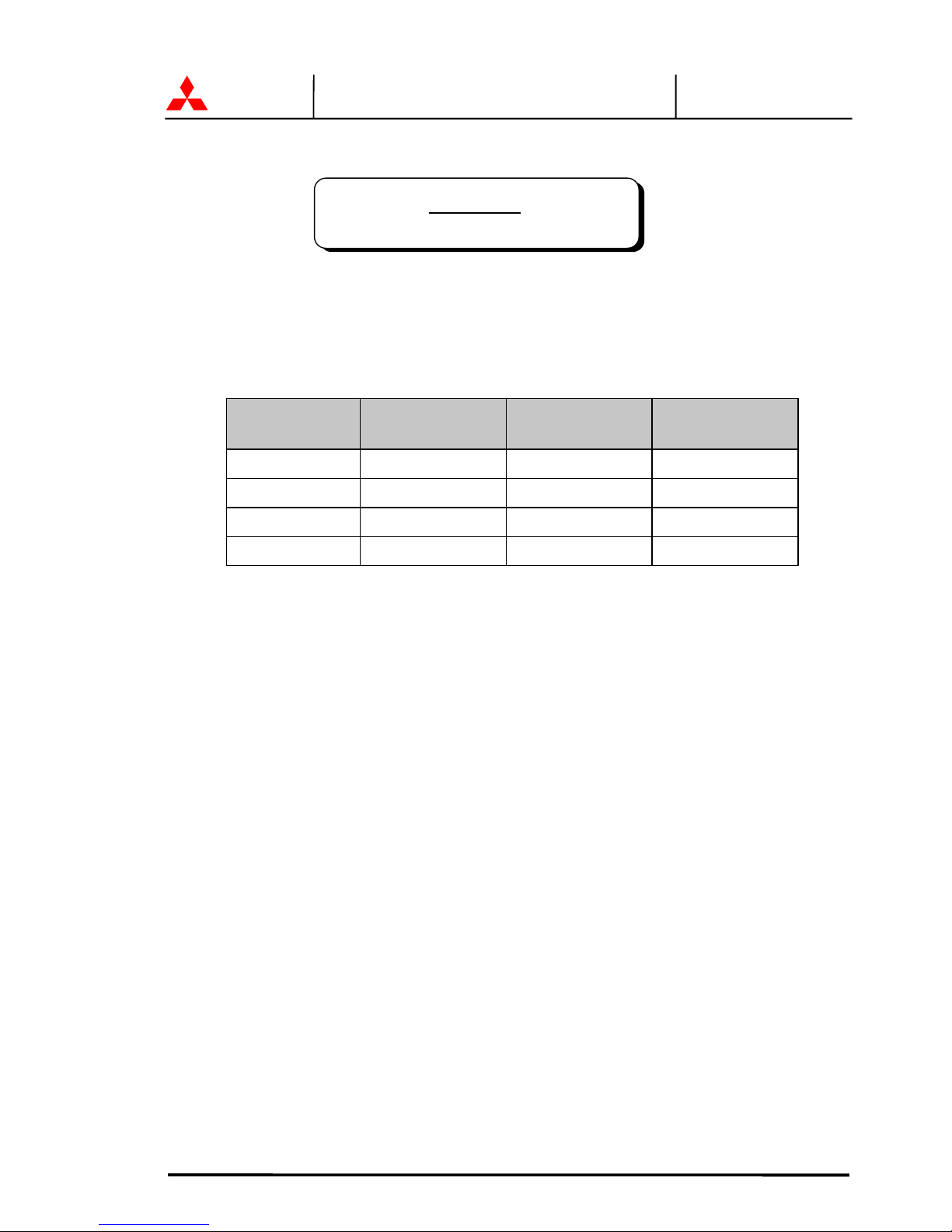
This UPS does not include an AC input circuit breaker (MCCB) to protect the bypass and
main input circuit. The AC input circuit breaker (MCCB) is to be field supplied and
installed. Circuit breaker (MCCB) sp eci fi cati on s are as follows:
Capacity
(kVA)
AC input
Voltage (Vac)
AC input Rating
(Aac)
Recommended
Breaker (A)
6 208 26.4 35
8 208 35.2 45
10 208 44.0 60
12 208 52.8 70
AC output and DC input overcurrent protection and disconnection devices shall be field
supplied and installed.
WARNING 2

MITSUBISHI ELECTRIC 7011A SERIES UPS
MITSUBISHI
ELECTRIC
7011A SERIES UPS
OWNERS / TECHNICAL MANUAL
Page Number:
1-3
1.1 GENERAL
The Mitsubishi 7011A Series UPS is designed to provide continuous and clean electrical
power to a critical load. In the event of an input power failure, the UPS will supply power to
the critical load for the specif ied battery time.
If the input power is not restored promptly, backup power from the UPS battery permits the
orderly shutdown of equipment supported by the UPS. The UPS is simple to start up,
operate and maintain.
The 7011A Series UPS is available in four (4) kVA sizes: 6, 8, 10 and 12kVA. Specifications
for each kVA model appear in Section 1.4. All models have batteries included in the UPS
module cabinet. The principles of operation described here in are applicable to all models.
This manual provides an overview of the 7011A Series components and their functions. The
appearance and purpose of operator controls and indicators is described with procedures for
operation, start-up, shutdown and basic maintenance included.

MITSUBISHI ELECTRIC 7011A SERIES UPS
MITSUBISHI
ELECTRIC
7011A SERIES UPS
OWNERS / TECHNICAL MANUAL
Page Number:
1-4
1.2 DEFINITION S
UNINTERRUPTIBLE POWER SUPPLY SYSTEM (UPS) - All components within the UPS
Module Cabinet and associated batteries which function as a system to provide continuous,
conditioned AC power to a load. This is sometimes referred to as the "Sy s t em".
UPS MODULE CABINET - The metal enclosure which contains Converter & Inverter
Module, I/O Module, batteries, and operator controls required to provide specified AC power
to a load.
CONVERTER & INVERTER MODULE - The Converter / Charger and Inverter assembly
which, under the direction of the I/O Module and operator controls, provide specified AC
power to a load.
I/O MODULE – Assembly which contains Static Transfer Switch, the internal bypass line,
and the internal control system. With operator controls, gives directions required to the
Converter & Inverter Module to provide specified AC power to a lo ad.
CONVERTER / CHARGER - The UPS component which contain the equipment and controls
necessary to convert input AC power to regulated DC power required for battery charging
and for supplying power to th e I nverter.
INVERTER – The UPS component which contain the equipment and controls necessary to
convert DC power from the Converter / Charger, or the battery, to AC power required by the
critical load.
STATIC TRANSFER SWITCH - Device which connects critical load to the bypass line when
the Inverter cannot supply co nt inuous power.
MAINTENANCE BYPASS LINE - Line which conducts electricity directly from the input power
source to the critical load during maintenance or whenever the UPS is not completely
operational.
AC INPUT POWER - Power provided by the electrical utility company, or auxiliary generator,
which is connected to the UPS for supplying critical load and recharging the battery.
BATTERY - Rechargeable battery strings which supply DC power to the inverter to maintain
continuous AC power to the load during AC input power failure c onditions.
MITSUBISHI ELECTRIC 7011A SERIES UPS
MITSUBISHI
ELECTRIC
7011A SERIES UPS
OWNERS / TECHNICAL MANUAL
Page Number:
1-5
1.3 OVERVIEW
The UPS provides two power paths between the utility source and the critical load. Figure 1.1
shows the path for normal operation, with the load powered from the inverter. Figure 1.2 shows
the path for bypass operation, w it h t he load supplied through the static bypass li ne.
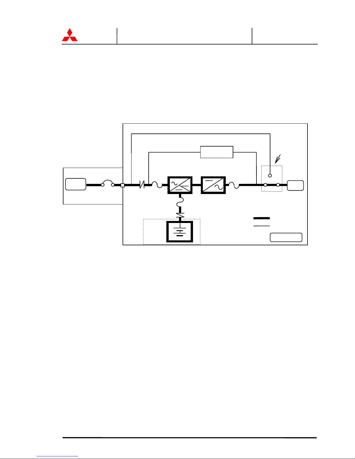
FIGURE 1.1 Single Line Diagram - Normal Operation. Load powered by inverter.
During normal operation, t he path through the inverter is used to pow er t he load.
Referring to Figure 1.1: Input AC power is converted to DC by the Converter. DC power is
utilized to charge the UPS battery and to provide power to the Inverter. The Inverter converts the
DC power to clean AC power to supp ly the critical load.
The conversion - inversion proc ess eliminates any voltage transients or fluctuations existing i n t he
input power before it reaches th e critical load.
* The Input circuit breaker(MCCB) for protection of the UPS and cables
are field supplied and field installed. (See WARNING 2 in section 1.0).
AC input
CB
User supplied
MCCB
UPS Cabinet
Static Transfe
r
Switch
Power Flow
N
ot in Use
FB
CB2
CONVERTER
INVERTER
Output
CB1
F
I
FO
BATTERY
52CS
Maintenance
Bypass Switch

MITSUBISHI ELECTRIC 7011A SERIES UPS
MITSUBISHI
ELECTRIC
7011A SERIES UPS
OWNERS / TECHNICAL MANUAL
Page Number:
1-6
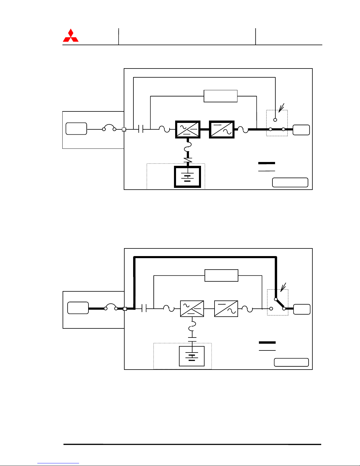
FIGURE 1.2 Single Line Diagram - Bypass Operation. Load fed through static bypass line.
Referring to Figure 1.2, the Internal Static Bypass line is a hard-wired line which supplies the
critical load with unconditioned input power. The purpose of this line is to route power to the
critical load while the UPS module is de-energized (converter and inverter), and during Start-up
before the system is fully operational.
The internal control system determines the operation of the two paths, with the load powered
from the inverter being the nor ma l operation.
Referring to Figure 1.3, if the input power is interrupted, the battery will immediately supply the
DC power required by the Inverter to maintain continuous AC power to the load. A fully charged
battery will provide p o w er for the specified time at t he r at ed load, or longer at reduced load.
When power is restored after a low battery shutdown, the Converter automatically restarts
operation, recharges the batteries and the Inverter is automatically restarted without operator
intervention. The load is assu med by the inverter automatically w it hout operator intervention.
In the event of a power failure, the Converter will de-energize and the batteries will discharge into
the Inverter and maintain power to the critical load until a) the battery capacity expires and the
inverter turns off, or b) input power is restored after which the converter will power the inverter
and simultaneously recharge the batteries. Figure 1.3 illustrates the flow diagram during battery
operation.
Maintenance
Bypass Switch
FB
BATTERY
CB2
Static Transfer
Switch
Power Flow
N
ot in Use
Output
CB1
F
I
FO
CONVERTER INVERTER
UPS Cabinet
52CS
AC input
CB
User supplied
MCCB
MITSUBISHI ELECTRIC 7011A SERIES UPS
MITSUBISHI
ELECTRIC
7011A SERIES UPS
OWNERS / TECHNICAL MANUAL
Page Number:
1-7
FIGURE 1.3 Single Line Diagram - Battery Operation
The UPS is equipped with an internal rotary type Maintenance Bypass Switch (MBS) that can be
used to divert utility power to the load during maintenance sessions. Figure 1.4 illustrates the
power path when the MBS is in t he BY PASS mode.
FIGURE 1.4 Single Line Diagram - UPS on Maintenance Bypass Operation.
UPS Cabinet
FB
BATTERY
CB2
Static Transfer
Switch
Power Flow
N
ot in Use
FO
CONVERTER INVERTER
Output
AC input
CB
User supplied
MCCB
Maintenance
Bypass Switch
CB1
F
I
52CS
UPS Cabinet
FB
BATTERY
CB2
Static Transfe
r
Switch
Power Flow
N
ot in Use
Output
CB1
F
I
FO
AC input
CB
User supplied
MCCB
CONVERTER
INVERTER
Maintenance
Bypass Switch
52CS
MITSUBISHI ELECTRIC 7011A SERIES UPS
MITSUBISHI
ELECTRIC
7011A SERIES UPS
OWNERS / TECHNICAL MANUAL
Page Number:
1-8
The rotary maintenance bypass switch is shown as 52CS in Figure 1.4. 52CS is a two position
four point make-before-break transf er sw it ch.
The two positions are identified as NORMAL and BYPASS. In the NORMAL position the load is fed
by the UPS - either through the inverter or through the static bypass line. In the BYPASS position
the load is powered by an external source such as the utility or a generator. This transfer operation
must be made while the UPS is in the static bypass mode.
For transfer procedure to place the UPS in maintenance bypass mode, or from bypass mode to
normal operation mode, refer to section 3.6 Maintenance Bypass Set-up Procedures.
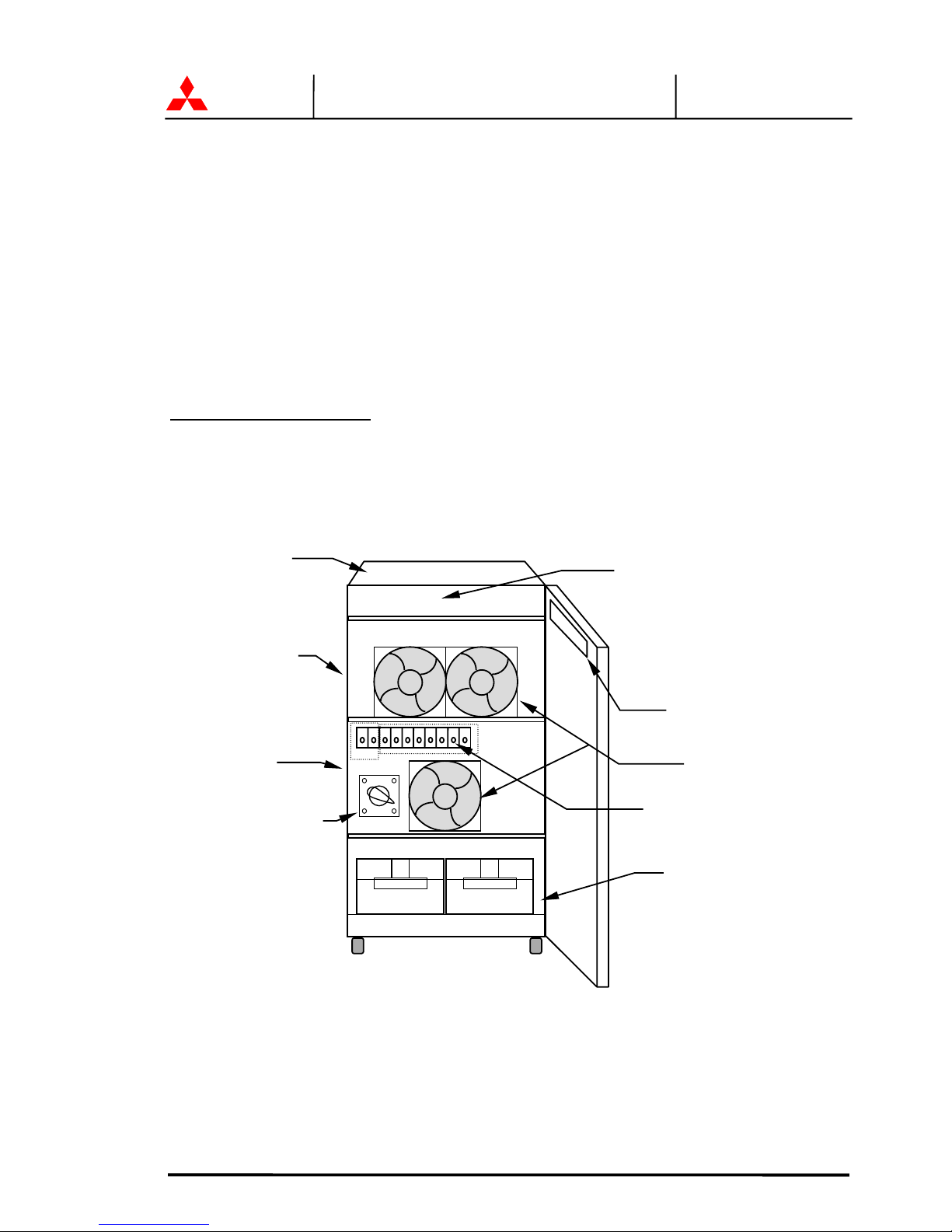
(For Service Personnel Only)
FIGURE 1.5 UPS Parts Location(6kVA)
.
1.Relay I/F PCB
RYER-A
UPS module
FRONT VIEW
Converter &
Inverte
r
Battery
Display PCB
DPAU-63
I/O Module
3.Module Connection
terminal
Cooling fan
2.Maintenance bypass
transfer switch
52CS
Main PCB
UPFR-L
 Loading...