

Page 1
Page 2

Page 3

Introduction of <CNC 70 Series Maintenance Training> Course
Course name : CNC 70 Series maintenance
Maximum number
of trainees
: 5
Aim of the course : to learn about maintenance of CNC 70 Series
Intended trainees : Engineers in charge of NC machine tool maintenance
Textbook to use : CNC 70 Series Maintenance Course
NC model to use : CNC 70 Series
Curriculum (One-day course)
Date Time Contents
Day ( ) Month ( )
Orientation
9:15
NC system hardware configuration
to
Maintenance and diagnosis screens
12:00
Data input/output operation and practice
NC alarms and part replacement practice
13:00
to
NC setup and practice
Drive system maintenance and part
The entry of
participation
record
16:30
replacement practice
Drive system alarms and their remedies
Page 4

Page 5

Preface
This textbook is designed to be used in "CNC 70 Series maintenance training course".
Operations and procedures described in this textbook are basically standard ones. Therefore, they
may be different from yours, depending on your NC model, machine tool builder , machine type, and so
on. Before you carry out actual maintenance such as part replacement, we recommend you to consult
with our service center.
As this textbook has been written based mostly on the following manuals, please refer to them for the
details.
• 700/70 Series Instruction Manual..................................................................IB-1500041
• 700/70 Series Setup Manual......................................................................... IB-1500123
• 70 Series Connection Manual.......................................................................IB-1500253
• MDS-D/DH Series Instruction Manual...........................................................IB-1500024
• MDS-D-SVJ3/SPJ3 Series Instruction Manual.............................................. IB-1500192
Page 6

Page 7

Contents
1. 70 Series System Configuration.........................................................................................................................1
1.1 NC Configuration...........................................................................................................................................1
1.2 System Configuration ....................................................................................................................................2
1.2.1 System Basic Configuration Drawing......................................................................................................2
1.2.2 General Connection Diagram..................................................................................................................3
1.2.3 List of Configuration Units.......................................................................................................................5
1.2.3.1 Control Unit: FCU7-MU521/FCU7-MU522........................................................................................5
1.2.3.2 Display Unit: FCU7-DU120-12/FCU7-DU140-12/FCU7-DU140-32 .................................................5
1.2.3.3 Operation Panel I/O Unit: FCU7-DX7xx............................................................................................6
1.2.3.4 Keyboard Unit: FCU7-KB024/ FCU7-KB044....................................................................................7
1.2.3.5 Remote I/O Unit:
FCUA-DX100/FCUA-DX110/FCUA-DX120/FCUA-DX140/FCUA-DX101/FCUA-DX111/
FCUA-DX121/FCUA-DX141.........................................................................................................................7
1.2.3.6 Scan I/O Card: HR357/HR347..........................................................................................................7
1.2.3.7 Card-sized I/O Card: HR361/HR371/HR381/HR383........................................................................8
1.2.3.8 External Power Supply Unit: PD25/PD27.........................................................................................8
2. Maintenance Screens.........................................................................................................................................9
2.1 Input/Output Screen ......................................................................................................................................9
2.1.1 Changing the Valid Area........................................................................................................................12
2.1.2 Selecting a Device, Directory and File..................................................................................................13
2.1.3 Transferring a File .................................................................................................................................20
2.1.4 Comparing Files (Compare)..................................................................................................................22
2.1.5 Formatting an External Device..............................................................................................................23
2.1.6 List of File Names..................................................................................................................................23
2.2 All Backup Screen........................................................................................................................................24
2.2.1 Performing a Backup Operation............................................................................................................26
2.2.2 Performing a Restore Operation...........................................................................................................26
2.2.3 Setting Automatic Backup.....................................................................................................................27
2.2.4 Backing up the SRAM...........................................................................................................................28
2.3 Absolute Position Setting Screen................................................................................................................30
2.3.1 Selecting the Axis..................................................................................................................................32
2.3.2 Carrying Out Dogless-type Zero Point Initialization ..............................................................................33
2.3.3 Carrying Out Dog-type Zero Point Initialization.....................................................................................41
2.3.4 Precautions............................................................................................................................................41
3. Diagnosis Screens............................................................................................................................................44
3.1 System Configuration Screen......................................................................................................................44
3.2 Option Display Screen.................................................................................................................................47
3.3 I/F Diagnosis Screen ...................................................................................................................................48
3.3.1 Displaying the PLC Device Data...........................................................................................................51
3.3.2 Carrying Out Modal Output ...................................................................................................................52
3.3.3 Carrying Out One-shot Output ..............................................................................................................53
3.4 Drive Monitor Screen...................................................................................................................................54
3.4.1 Servo Axis Unit Display Items...............................................................................................................56
3.4.2 Spindle Unit Display Items.....................................................................................................................59
3.4.3 Display Items for the Power Supply Unit...............................................................................................68
3.4.4 Display Items for the Synchronous Error ..............................................................................................70
3.4.5 Clearing the Alarm History.....................................................................................................................71
3.5 NC Memory Diagnosis Screen (NC Memory Diagn Screen) ......................................................................72
3.5.1 Writing/Reading the Data Using the NC Data Designation...................................................................74
3.6 Alarm Screen ...............................................................................................................................................75
3.6.1 Alarm History .........................................................................................................................................77
3.7 Self Diagnosis Screen .................................................................................................................................79
4. NC's Maintenance Check and Replacement Procedure..................................................................................83
4.1 Maintenance Items ......................................................................................................................................83
4.1.1 Escutcheon............................................................................................................................................83
4.1.2 LCD Panel.............................................................................................................................................84
Page 8

4.1.3 Compact Flash/IC card..........................................................................................................................84
4.2. H/W Replacement Methods........................................................................................................................85
4.2.1 Durable Parts.........................................................................................................................................85
4.2.1.1 Control unit battery..........................................................................................................................85
4.2.1.2 Backlight..........................................................................................................................................87
4.2.2 Unit........................................................................................................................................................89
4.2.2.1 Control Unit.....................................................................................................................................89
4.2.2.2 Display Unit.....................................................................................................................................91
4.2.2.3 Keyboard unit..................................................................................................................................92
4.2.2.4 DX Unit............................................................................................................................................94
4.2.3 Compact Flash ......................................................................................................................................95
4.2.3.1 Front Compact Flash.......................................................................................................................95
5. NC Setup Procedures.......................................................................................................................................96
5.1 Setup Procedure after SRAM Clear ............................................................................................................96
5.1.1 Outline of Hardware Configuration........................................................................................................96
5.1.2 Outline of Setup Procedures.................................................................................................................97
5.2 Setup Details ...............................................................................................................................................99
5.2.1 Erasing the backed up data (SRAM).....................................................................................................99
5.2.2 Inputting the Parameters.....................................................................................................................100
5.2.2.1 When There is No Parameter File ................................................................................................100
5.2.2.2 When a Parameter File is Av ailable..............................................................................................101
5.2.2.3 Parameter Screens.......................................................................................................................102
5.2.3 Formatting the File System .................................................................................................................113
5.2.4 Integrated Time Display.......................................................................................................................114
5.2.4.1 Setting the Integrated Time...........................................................................................................115
5.2.4.2 Setting the Time Display Selection...............................................................................................116
5.2.5 Credit System......................................................................................................................................117
5.2.6 Absolute Position Detection System ...................................................................................................119
5.2.6.1 Dog-type Reference Position Return Operation...........................................................................119
5.2.6.2 Starting up the Absolute Position Detection System.....................................................................120
5.2.7 PLC Switch Function...........................................................................................................................122
5.2.7.1 Turning PLC Switches ON/OFF....................................................................................................123
5.3 7-segment LED's Alarm/Status Indication .................................................................................................124
5.3.1 Outline.................................................................................................................................................124
5.3.2 Status Display......................................................................................................................................124
5.3.3 Alarm Display ......................................................................................................................................124
5.3.4 Notes...................................................................................................................................................125
5.3.5 Example of alarm display....................................................................................................................126
6. Drive Unit Maintenance...................................................................................................................................134
6.1 MDS-D/DH Series......................................................................................................................................134
6.1.1 Part system connection diagram.........................................................................................................134
6.1.2 Maintenance........................................................................................................................................135
6.1.2.1 Inspections....................................................................................................................................135
6.1.2.2 Service parts.................................................................................................................................135
6.1.2.3 Adding and replacing units and parts............................................................................................136
6.1.2.3.1 Replacing the drive unit..........................................................................................................136
6.1.2.3.2 Replacing the unit fan.............................................................................................................137
6.1.2.3.3 Replacing the battery..............................................................................................................138
6.1.2.3.4 Replacing the fuse..................................................................................................................140
6.2 MDS-D-SVJ3/SPJ3 Series........................................................................................................................141
6.2.1 Part system connection diagram.........................................................................................................141
6.2.2 Maintenance........................................................................................................................................142
6.2.2.1 Inspections....................................................................................................................................142
6.2.2.2 Service parts.................................................................................................................................142
6.2.2.3 Adding and replacing units and parts............................................................................................143
6.2.2.3.1 Replacing the drive unit..........................................................................................................143
6.2.2.3.2 Replacing the unit fan.............................................................................................................144
6.2.2.3.3 Replacing the battery..............................................................................................................145
7. Servo System Maintenance............................................................................................................................146
7.1 D/A output specifications for servo drive unit ............................................................................................146
7.1.1 MDS-D/DH Series...............................................................................................................................146
Page 9

7.1.1.1 D/A output specifications...............................................................................................................146
7.1.1.2 Setting the output data..................................................................................................................147
7.1.1.3 Setting the output magnification....................................................................................................148
7.1.2 MDS-D-SVJ3 Series............................................................................................................................149
7.1.2.1 D/A output specifications...............................................................................................................149
7.1.2.2 Setting the output data..................................................................................................................150
7.1.2.3 Setting the output magnification....................................................................................................151
7.2 Vibration Suppression................................................................................................................................152
7.2.1 Notch filte.............................................................................................................................................152
8. Spindle System Maintenance .........................................................................................................................153
8.1 D/A output specifications for spindle drive unit..........................................................................................153
8.1.1 MDS-D/DH Series...............................................................................................................................153
8.1.1.1 D/A output specifications...............................................................................................................153
8.1.1.2 Setting the output data..................................................................................................................154
8.1.1.3 Setting the output magnification....................................................................................................156
8.1.2 MDS-SPJ3 Series ...............................................................................................................................157
8.1.2.1 D/A output specifications...............................................................................................................157
8.1.2.2 Setting the output data..................................................................................................................158
8.1.2.3 Setting the output magnification....................................................................................................160
8.2 Diagnostic Procedure When Vibration/Noise Occurs................................................................................161
8.2.1 How to judge whether the cause is on machine side or control unit side...........................................161
8.2.2 How to judge PLG trouble...................................................................................................................161
8.2.3 How to check PLG waveform..............................................................................................................162
8.2.3.1 Configuration of serial detector TS5691.......................................................................................162
8.2.3.2 Adjust A and B phase signals........................................................................................................163
8.2.3.3 Check Z phase signal....................................................................................................................164
8.3 Adjustment of Orientation Stop Position....................................................................................................166
9. Servo/Spindle's T roubleshooting.....................................................................................................................167
9.1 MDS-D/DH Series......................................................................................................................................167
9.1.1 Points of caution and confirmation......................................................................................................167
9.1.1.1 LED display when alarm or warning occurs..................................................................................168
9.1.2 Protective functions list of units...........................................................................................................169
9.1.2.1 List of alarms.................................................................................................................................169
9.1.2.2 List of warnings.............................................................................................................................173
9.1.3 Troubleshooting...................................................................................................................................176
9.1.3.1 Troubleshooting at power ON.......................................................................................................176
9.1.3.2 Troubleshooting for each alarm No...............................................................................................177
9.1.3.3 Troubleshooting for each warning No...........................................................................................200
9.1.3.4 Parameter numbers during initial parameter error........................................................................202
9.1.3.5 Troubleshooting the spindle system when there is no alarm or warning......................................203
9.2 MDS-D-SVJ3/SPJ3 Series........................................................................................................................205
9.2.1 Points of caution and confirmation......................................................................................................205
9.2.1.1 LED display when alarm or warning occurs..................................................................................206
9.2.2 Protective functions list of units...........................................................................................................207
9.2.2.1 List of alarms.................................................................................................................................207
9.2.2.2 List of warnings.............................................................................................................................210
9.2.3 Troubleshooting...................................................................................................................................213
9.2.3.1 Troubleshooting at power ON.......................................................................................................213
9.2.3.2 Troubleshooting for each alarm No...............................................................................................214
9.2.3.3 Troubleshooting for each warning No...........................................................................................232
9.2.3.4 Parameter numbers during initial parameter error........................................................................234
9.2.3.5 Troubleshooting the spindle system when there is no alarm or warning......................................235
10. Appendix.......................................................................................................................................................237
10.1 List of Alarms...........................................................................................................................................237
10.1.1 Operation Alarms...............................................................................................................................237
10.1.2 Stop Codes........................................................................................................................................245
10.1.3 Servo/Spindle Alarms........................................................................................................................249
10.1.4 MCP Alarm ........................................................................................................................................258
10.1.5 System Alarms ..................................................................................................................................268
10.1.6 Absolute Position Detection System Alarms.....................................................................................274
10.1.7 Distance-coded Reference Scale Errors...........................................................................................277
Page 10

10.1.8 Messages during Emergency Stop ...................................................................................................278
10.1.9 Computer Link Errors........................................................................................................................280
10.1.10 User PLC Alarms.............................................................................................................................281
10.1.1 1 Network Service Errors....................................................................................................................283
10.2 RS-232C I/O Device Parameter Setting Examples.................................................................................284
Page 11
1. 70 Series System Configuration
C
A
A
1. 70 Series System Configuration
1.1 NC Configuration
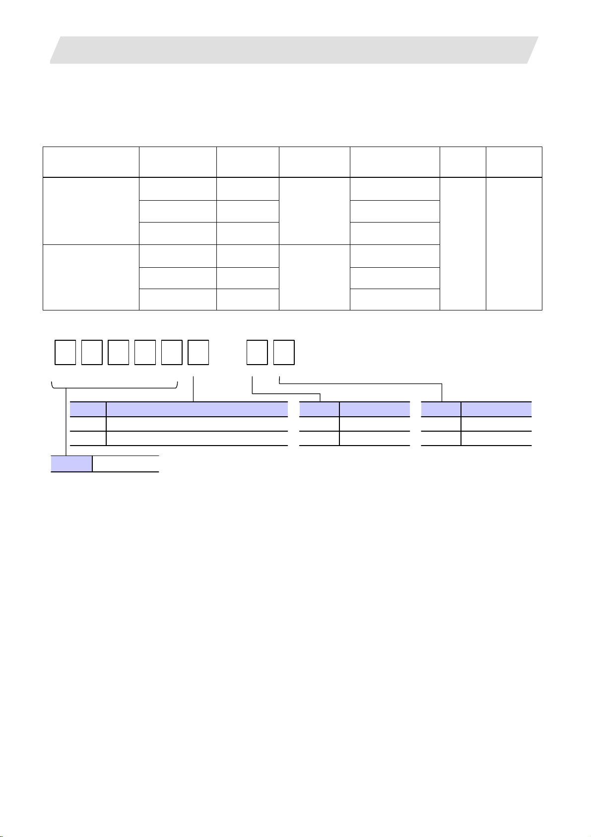
70 Series configuration
MITSUBISHI CNC 70
Type A
MITSUBISHI CNC 70
Type B
F
System model
name
FCA70P-2A 8.4" LCD FCU7-DU120-12
FCA70P-4A 10.4" LCD FCU7-DU140-12
FCA70H-4A 10.4" LCD
FCA70P-2B 8.4" LCD FCU7-DU120-12
FCA70P-4B 10.4" LCD FCU7-DU140-12
FCA70H-4B 10.4" LCD
7 0 P
-
Display
size
4
Control unit
name
FCU7-MU522
FCU7-MU521
1.1 NC Configuration
Display unit name
FCU7-DU140-32
FCU7-DU140-32
Machine
type
Common
to M/L
System #
BND-
1009W000
Hardware type Code
Panel-in type (without touch panel specification)
P
Panel-in type (with touch panel specification)*
H
M70 Series FCA70
* Reserved for future expansion
There are six types of M70 H/W configurations
Display unit sizeCode
8.4 inch 2
10.4 inch 4
Type Code
Type A A
Type B B
1
Page 12
1. 70 Series System Configuration
1.2 System Configuration
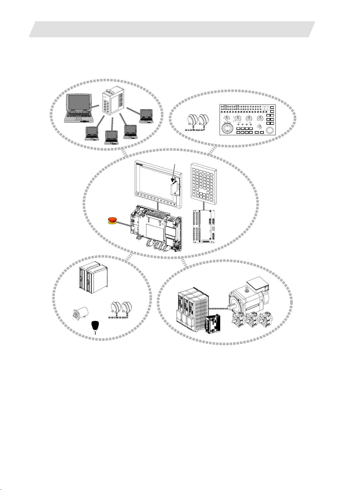
1.2.1 System Basic Configuration Drawing
Ethernet
hub
Personal
computer
Display unit
CF card I/F
Manual pulse
generator
1.2 System Configuration
Machine operation panel
MF MCODEDATA
TF TCODEDATA
SW1 SW9 SW10 SW11 SW12 SW13 OVSL OVC SRN F1DSW8SW7SW6SW5SW4SW3SW2
10
1
-+
Keyboard unit
100
1000
5000
10000
50000
100000
AL1 AL2 AL3 AL4 TAP DEN OP SA MA
SFLED29LED30 LED31LED32 LED33LED34LED35LED36
RAP ID
STEP
R-P OINTRETURN
JOG
X
HANDLE
MEM
Y
MDI
Z
TAPE
4
1STREFERENCEPOSITIO N
+X +4+Z+Y
-X -4-Z-Y FEEDHOLDCYCLESTART
MANUAL FEEDRATE
100
52
27
20
10
REACHED
DEGITALSWITCH
RESET
CUTTIN GFEEDRATEOVERRIDEMODE SELECTHANDLE/STEPMULTIPLICATION
520
100
720
110
270
90
1000
80
120
200
130
1400
70
140
2000
60
MACHINELOCK
2700
50
150
160
40
3700
30
170
5200
2
180
20
7200
10
190
1
10000
mm/mi n
%
0
0
SIN GLEBLOCK
200
14000
RAPIDTRAVERSEOVERRID E
4ZYX
100
50
25
EMERGENCYSTOP
1
ON
OFF
FIN
MSTLOCK
DRYRUN
Control unit
Operation panel
I/O unit
Synchronous feed
encoder
Emergency
stop switch
Remote I/O
unit
Manual pulse
generator
Servo/Spindle drive units
MDS-D/DH Series
MDS-D-SVJ3/SPJ3 Series
Skip
(Note 1) Control unit is mounted on the back side of the display unit.
(Note 2) Operation panel I/O unit is mounted on the back side of the keyboard unit.
Motors
2
Page 13
1. 70 Series System Configuration
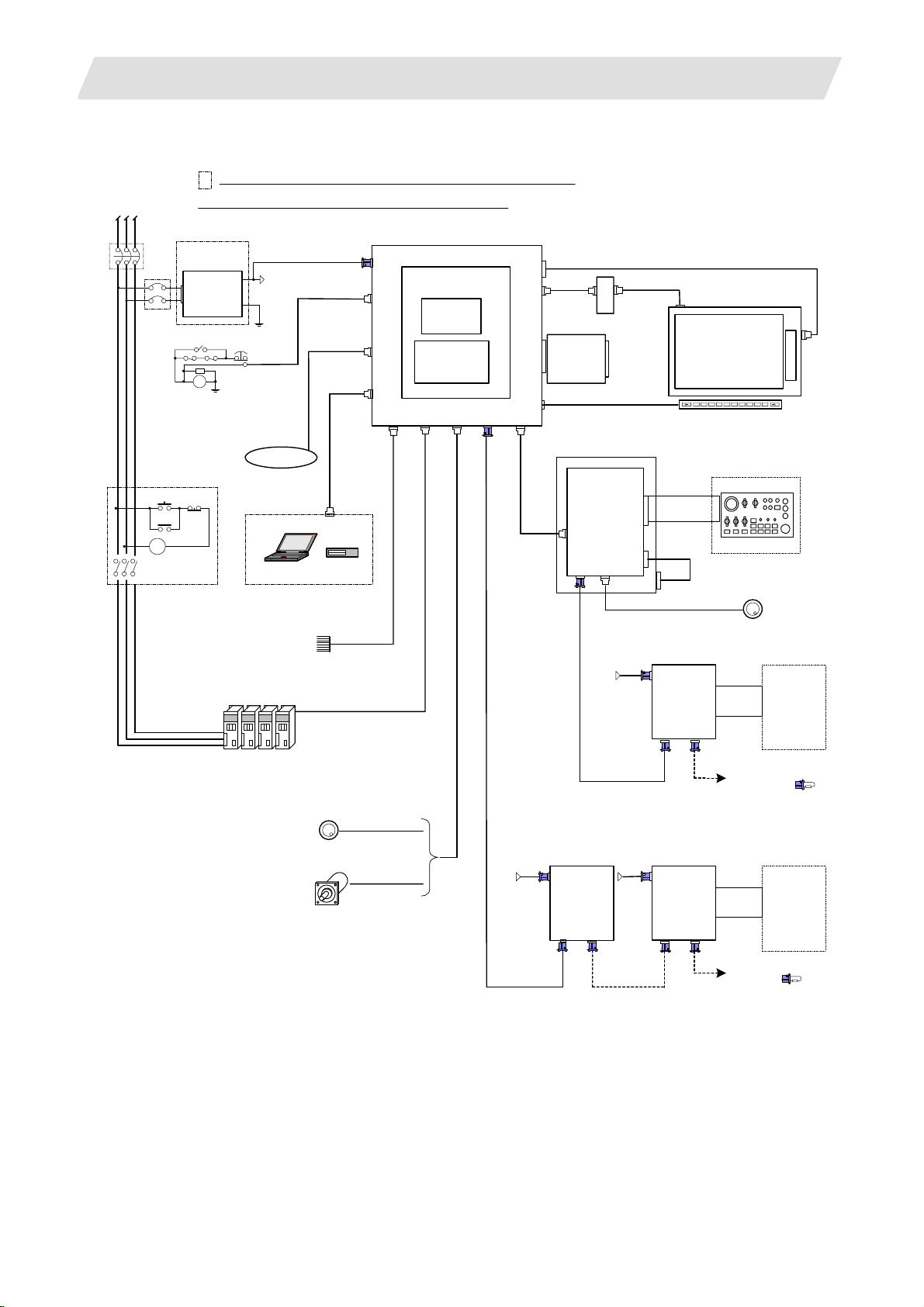
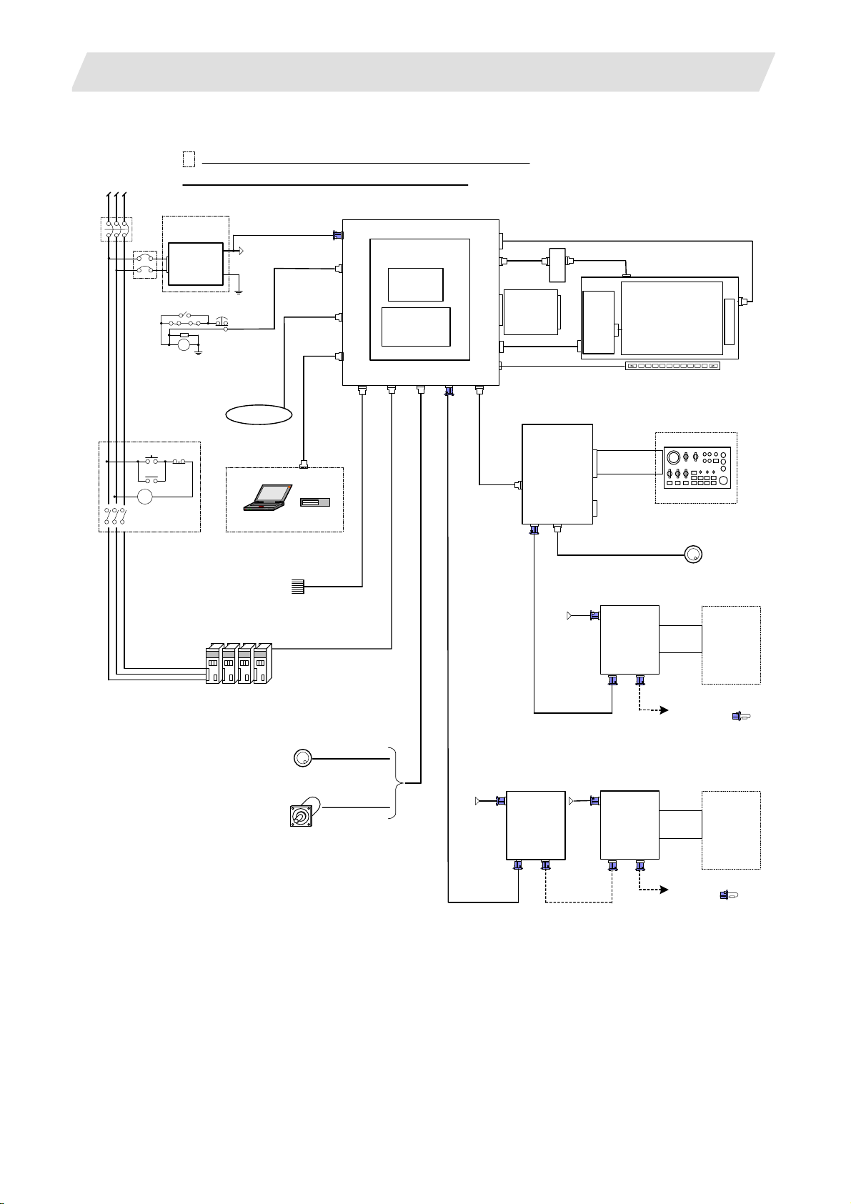
1.2.2 General Connection Diagram
(1) Without Touch Panel
Dotted lines indicate the sections prepared by machine tool builder.
RST
No-fuse breaker(NFB)
NFB
MC
MC
The name with brackets <> indicates the cable for the unit.
24VDC
stabilized power
supply
DCOUT
ACIN
OT release switch
RA
ON OFF
MC
FG
EMG
FG
24VDC
FG
Network
Sensor signals
Max. 8 pints
F070
F120
G300/G301
RS232C Device
Skip signal input
1ch
USER 2ch
1ch: F034
2ch: F035
FCUA-R030
G395/G396/G380
CNC control unit
FCU7-MU521/522
DCIN
Main card HN76x
EMG
LAN
Memory card
Expansion
SIO
OPT
SKIP ENC
HN4xx
card
HN75x
RIO1
LCD
INV
FRONT
MENU
CG71
G011
max. 0.5m
<8.4-type: G097>
<10.4-type: G098>
<F480>
Backlight inverter
Front CF
card
HN791
Keyboard unit
FCU7-KB024/44
Operation panel
I/O unit
FCU7-DXxxx
CG3x
CG71
RIO3 MPG
1.2 System Configuration
<10.4-type: G482>
Display unit
8.4-type FCU7-DU120-12
10.4-type FCU7-DU140-12
(VGA:640×480)
Menu key
Machine operation panel
F351
<G402>
NCKB
Manual pulse generator
DI-L/R
RIO2RIO1
2ch
R300
Machine
control
relay/contact
24VDC
F070
12V:F320/F321
5V:F023/F024
Remote I/O unit
DCIN
FCUA-DX1xx
Spindle/Servo Drive Units
MDS-D/DH/SVJ3/SPJ3
Manual pulse generator
Sync. Encoder
2ch
5V:G023/G024
1ch
FCUA-R050/054
24VDC 24VDC
F070
FCUA-R211
/SH41
FCUA-R211
/SH41
Remote I/O unit
DCIN
FCUA-DX1xx
RIO2
RIO1
F070
FCUA-R211
/SH41
Remote I/O unit
DCIN
FCUA-DX1xx
DI-L/R
RIO2RIO1
To the next remote
I/O or terminator
Machine
control
relay/contact
R300
To the next remote I/O
or terminator
3
Page 14
1. 70 Series System Configuration
(2) With Touch Panel
Dotted lines indicate the sections prepared by machine tool builder.
RST
No-fuse breaker(NFB)
NFB
MC
MC
The name with brackets <> indicates the cable for the unit.
24VDC
stabilized power
supply
DCOUT
ACIN
OT release switch
RA
ON OFF
MC
FG
EMG
FG
24VDC
FG
Network
Sensor signals
Max. 8 pints
F070
F120
G300/G301
RS232C Device
Skip signal input
1ch
USER 2ch
1ch: F034
2ch: F035
FCUA-R030
G395/G396/G380
CNC control unit
FCU7-MU521/522
DCIN
Main card HN76x
EMG
LAN
Memory card
Expansion
SIO
OPT
SKIP ENC
HN4xx
card
HN75x
RIO1
LCD
INV
FRONT
TEST
MENU
CG71
G011
max. 0.5m
<G098>
<F480>
Backlight
inverter
Front CF
card
HN791
Operation panel
FCU7-DXxxx
CG71
RIO3 MPG
1.2 System Configuration
<G482>
HN244
Touch panel display unit
FCU7-DU140-32
<G422>
I/O unit
TPIN
TESTIN
CG3x
NCKB
Remote I/O unit
24VDC
F070
(VGA:640×480)
F351
12V:F320/F321
5V:F023/F024
DCIN
FCUA-DX1xx
DI-L/R
RIO2RIO1
Menu key
Machine operation panel
2ch
R300
Manual pulse generator
Machine
control
relay/contact
Spindle/Servo Drive Units
MDS-D/DH/SVJ3/SPJ3
Manual pulse generator
Sync. Encoder
2ch
5V:G023/G024
1ch
FCUA-R050/054
24VDC 24VDC
F070
FCUA-R211
/SH41
FCUA-R211
/SH41
Remote I/O unit
DCIN
FCUA-DX1xx
RIO2
RIO1
F070
FCUA-R211
/SH41
Remote I/O unit
DCIN
FCUA-DX1xx
DI-L/R
RIO2RIO1
To the next remote
I/O or terminator
Machine
control
relay/contact
R300
To the next remote I/O
or terminator
4
Page 15

1. 70 Series System Configuration
1.2.3 List of Configuration Units
1.2.3.1 Control Unit: FCU7-MU521/FCU7-MU522
Type Function Configuration element Details
FCU7-MU521 NC functions and
display controller
FCU7-MU522 NC functions and
display controller
Main control card (HN761)
Memory card (HN451)
CF I/F Card (HN791)
Main control card (HN761)
Memory card (HN451)
Expansion card (HN751)
CF I/F Card (HN791)
1.2.3.2 Display Unit: FCU7-DU120-12/FCU7-DU140-12/FCU7-DU140-32
Type Function Configuration element Details
FCU7-DU120-12 8.4-type color TFT LCD panel
Backlight inverter (84PW031)
Menu keys
G097 cable
FCU7-DU140-12 10.4-type color TFT LCD panel
Backlight inverter (104PW161)
Menu keys
G098 cable
G482 cable
FCU7-DU140-32 10.4-type color TFT LCD panel
touch panel Backlight inverter (104PW161)
Menu keys
Touch panel
Touch panel control card (HN244)
G098 cable
G422 cable
G482 cable
1.2 System Configuration
Export Trade Control Ordinance
and Foreign Trade Ordinance
noncompliant unit
Export Trade Control Ordinance
and Foreign Trade Ordinance
noncompliant unit
CF card I/F is normally equipped
with the control unit.
CF card I/F is normally equipped
with the control unit.
CF card I/F is normally equipped
with the control unit.
5
Page 16

1. 70 Series System Configuration
1.2.3.3 Operation Panel I/O Unit: FCU7-DX7xx
Type Function Configuration element Details
FCU7-DX710 DI/DO Sink/source input
DO sink output
Base card
Terminator
(HN341)
(R-TM)
1.2 System Configuration
DI/DO = 64 points/64 points + MPG 2ch
FCU7-DX711 DI/DO Sink/source input
DO source output
FCU7-DX720 DI/DO Sink/source input
DO sink output
FCU7-DX721 DI/DO Sink/source input
DO source output
DO sink output
DO source output
Base card
Terminator
Base card
Terminator
Add-on card (HN361) DI/DO = 32 points/16 points + AO 1ch
Base card
Terminator
Add-on card (HN371) DI/DO = 32 points/16 points + AO 1ch
Base card
Terminator
Add-on card (HN362) DI/DO = 32 points/32 points
Base card
Terminator
Add-on card (HN372) DI/DO = 32 points/32 points
(HN351)
(R-TM)
(HN341)
(R-TM)
(HN351)
(R-TM)
(HN341)
(R-TM)
(HN342)
(R-TM)
DI/DO = 64 points/64 points + MPG 2ch
DI/DO = 64 points/64 points + MPG 2ch
DI/DO = 64 points/64 points + MPG 2ch
DI/DO = 64 points/64 points + MPG 2chFCU7-DX730 DI/DO Sink/source input
DI/DO = 64 points/64 points + MPG 2chFCU7-DX731 DI/DO Sink/source input
(Note 1) Operation panel I/O unit is mounted on the back side of the keyboard unit
FCU7-KB024/KB026/KB044.
(Note 2) Operation panel I/O unit for 700 Series is not available.
6
Page 17

1. 70 Series System Configuration
1.2 System Configuration
1.2.3.4 Keyboard Unit: FCU7-KB024/ FCU7-KB044
Type Function Configuration element Details
FCU7-KB024 8.4-type display keyboard Escutcheon, key switch Connect with G011 cable from control unit.
Sheet keys G402 cable Mounting method: Mount on front panel
FCU7-KB026 8.4-type display keyboard Escutcheon, key switch Connect with G011 cable from control unit.
Clear keys G402 cable Mounting method: Mount on front panel
FCU7-KB044 10.4-type display keyboard Escutcheon, key switch Connect with G011 cable from control unit.
Sheet keys G402 cable Mounting method: Mount on front panel
1.2.3.5 Remote I/O Unit: FCUA-DX100/FCUA-DX110/FCUA-DX120/FCUA-DX140/FCUA-DX101/FCUA-DX111/ FCUA-DX121/FCUA-DX141
Type Function Configuration element Details
FCUA-DX100 Sink/source input + sink output RX31 1 DI/DO = 32 points/32 points
FCUA-DX110 Sink/source input + sink output RX31 1+RX321-1 DI/DO = 64 points/48 points
FCUA-DX120 Sink/source input + sink output
+ analog output
FCUA-DX140 Sink/source input + sink output
+ analog input/output
FCUA-DX101 Sink/source input + source
output
FCUA-DX111 Sink/source input + source
output
FCUA-DX121 Sink/source input + source
output + analog output
FCUA-DX141 Sink/source input + source
output + analog input/output
RX311+RX321 DI/DO = 64 points/48 points
+ analog output 1 point
RX311+RX341 DI/DO = 32 points/32 points
+ analog input 4 points
+ analog output 1 point
RX312 DI/DO = 32 points/32 points
RX312+RX322-1 DI/DO = 64 points/48 points
RX312+RX322 DI/DO = 64 points/48 points
+ analog output 1 point
RX312+RX341 DI/DO = 32 points/32 points
+ analog input 4 points
+ analog output 1 point
1.2.3.6 Scan I/O Card: HR357/HR347
Type Function Configuration element Details
HR357 Scan I/O (source) HR357 Scan DI/DO = 64 points/64 points
DI/DO = 32 points/32 points
HR347 Scan I/O (sink) HR347 Scan DI/DO = 64 points/64 points
DI/DO = 32 points/32 points
7
Page 18

1. 70 Series System Configuration
1.2 System Configuration
1.2.3.7 Card-sized I/O Card: HR361/HR371/HR381/HR383
Type Function Configuration element Details
HR361 DI16 (sink/source)
+DO16 (sink)
HR371 DI32 (sink/source)
+DO16 (source)
HR381 AO x 1 HR381 AO x 1
HR383 AI x 4+AO x 1 HR383 AI x 4+AO x 1
HR361 DI/DO = 16 points/16 points
HR371 DI/DO = 16 points/16 points
1.2.3.8 External Power Supply Unit: PD25/PD27
Type Function Configuration element Details
PD25 External power supply with
power supply ON/OFF
function
PD27 External power supply with
power supply ON/OFF
function
Power supply card
Case set
Power supply card
Case set
Input 200VAC
Output 24VDC (3A)
Input 200V to 400VAC
Output 24VDC (8A)
8
Page 19
2. Maintenance Screens
2.1 Input/Output Screen
2. Maintenance Screens
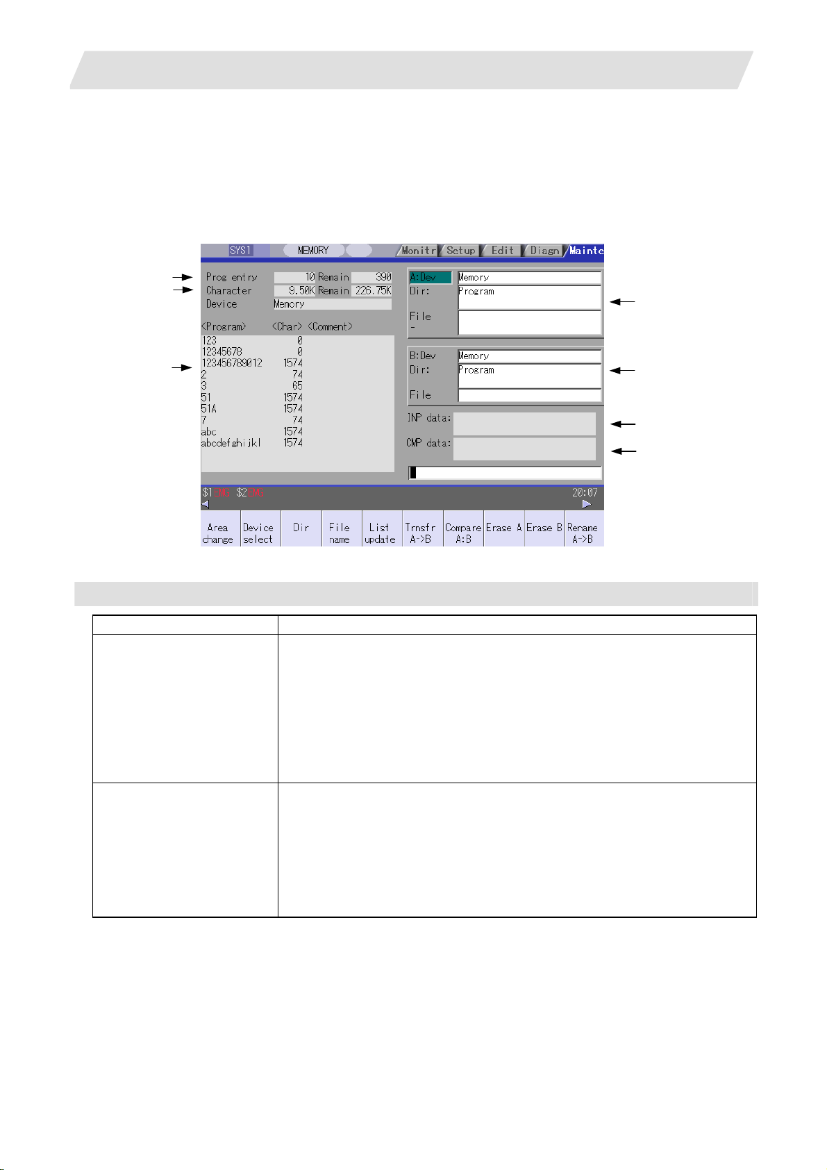
2.1 Input/Output Screen
The Input/Output screen is used to carry out NC data input/output between the NC internal memory and the
external input/output devices.
Here, the hard disk built into the NC device is also treated as external devices.
In 70 series, only "Memory", "Memory card", "Serial", "Ethernet" and "Anshin-net server" can be used.
(1)
(2)
(4)
(3)
Display items
Display item Details
(1) Number of programs
registered and remainder
(Note 1)
(2) Number of memory
characters and remainder
(Note 1)
(5)
(6)
(7)
This displays the registration information of machining program of the selected
device.
Number of programs registered :
This displays the number of programs previously registered as user machining
programs.
Remainder :
This displays the remaining number of programs that can be registered.
When "Memory" is selected as the device, the total of the number of programs
registered and the remainder is the maximum number of registrations set in the
specifications.
This displays the number of characters of the machining program of the selected
device.
Number of memory characters :
This displays the number of characters previously registered as user machining
programs.
Remainder :
This displays the remaining number of characters that can be registered. The total
of the number of memory characters and the remainder is the maximum number of
memory characters set in the specifications.
9
Page 20

2. Maintenance Screens
2.1 Input/Output Screen
Display items Details
List (Note 2)
(3)
(4) File setting column A
(5) File setting column B
(6) Input data This displays the data being transferred.
(7) Comparison data This displays the data being compared. If an error occurs during comparison, the
(Note 1) Depending on the device, some items are not displayed.
Device
Display item
Number of programs
registered
Remainder
Number of memory
characters
Remainder
List
* : When the Ethernet parameter "#97*1 Host n no tot al siz" is set to 1, the number of host memory
characters will not appear .
(Note 2) The list does not appear when using serial.
This displays a contents list (directory and file name) of the directory in the setting
column (file setting column A or B) where the cursor is currently located.
Program :
When "Memory" is selected for the device, this displays the file name (program No.)
of the machining programs already registered. The file names are displayed in
order from the smallest number, from 1 to 99999999. When a device other than
memory is selected, this displays the file name and directory to be included in the
directory that is set in the current setting column.
When the number of characters exceeds 12, the excess is indicated as "*".
Character :
The size of each file (when memory is selected for the device, the number of
characters in the machining program). When directory is selected, this displays
"DIR".
Comment :
This displays the comment (up to 17 alphanumeric characters and symbols) of
each file.
The date which the file is updated is displayed for the HD, FD, memory card, DS or
Ethernet.
When the number of characters exceeds 17, the excess is not displayed.
This sets the device, directory, and file name of the target file for transfer, compare,
erasing, etc., operations.
When transferring, the file name of the transfer origin file is set. When renaming, the
file name before renaming is set. When erasing, the erasing range is set. When the
number of characters exceeds 28, the excess is not displayed.
block with the error is displayed.
×
×
×
×
Memory
card
{ { { {
{ {
{ {
{ { { {
DS Ethernet FD
{ *
×
{ : Displayed × : Not displayed
Memory HD Serial
{ {
{
{ {
{ {
{ {
× × × × × × ×
{
{
Anshin-net
server
×
×
×
×
10
Page 21

2. Maintenance Screens
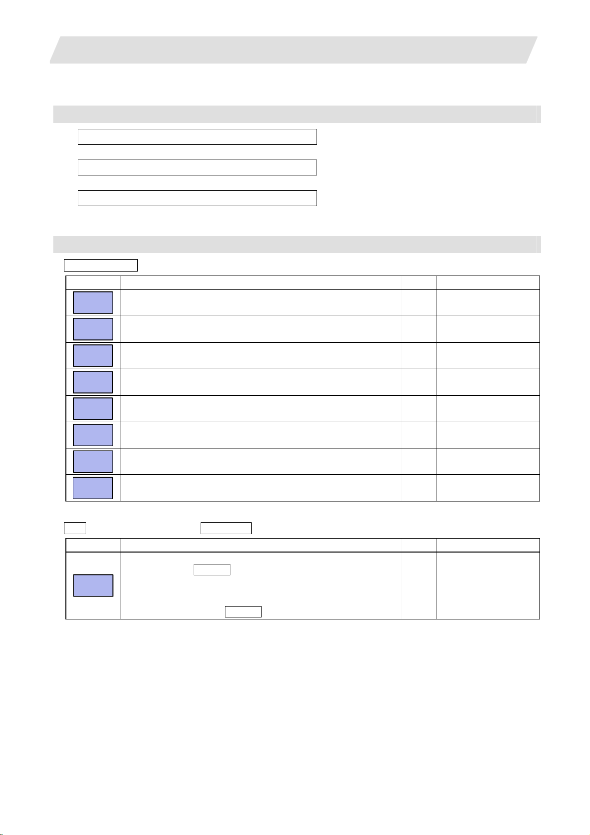
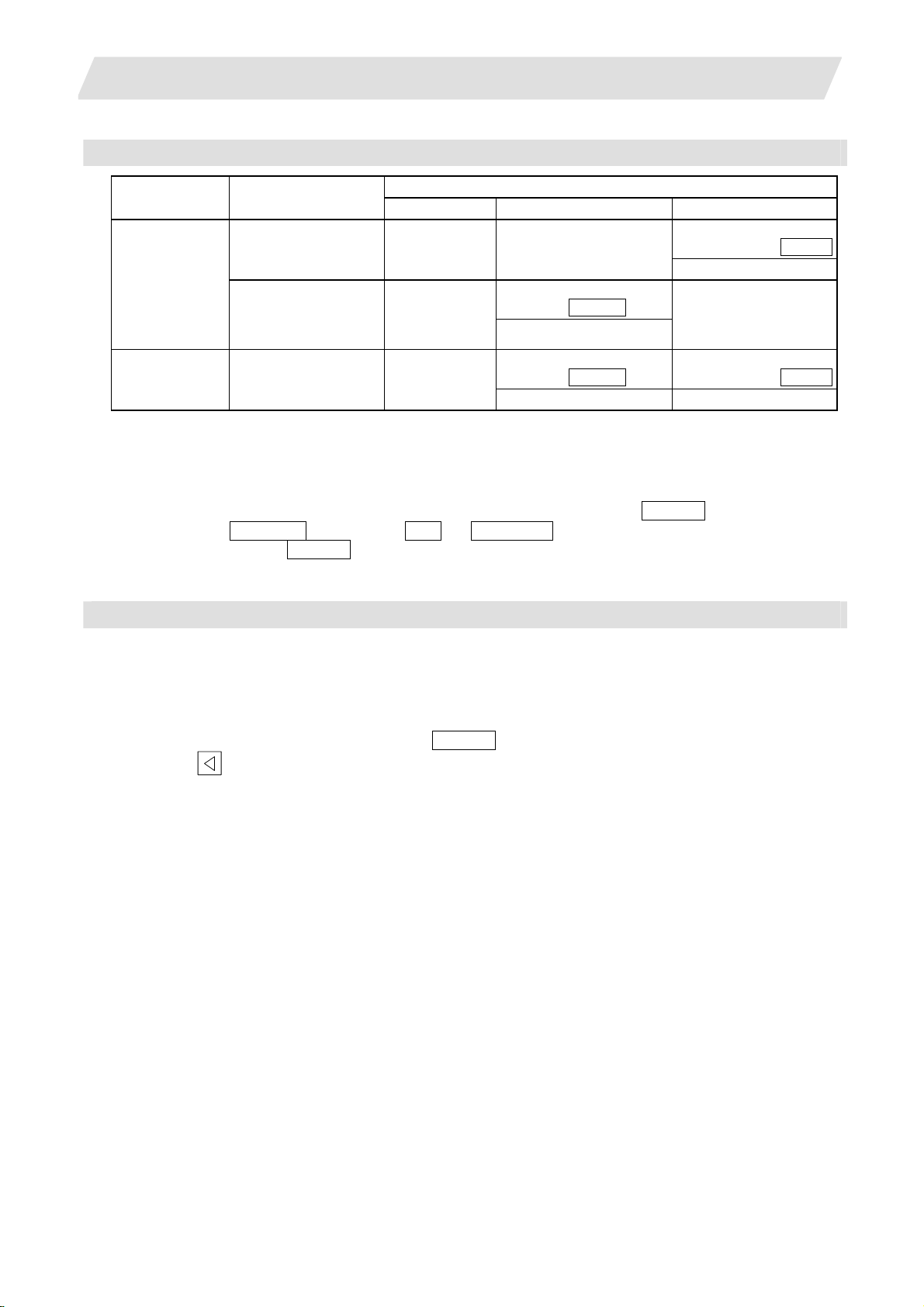
Menus
Menu Details Type Reference
Area
change
Device
select
Dir
File
name
List
update
Transfr
A→B
Compare
A:B
Erase A
Erase B
Rename
A→B
Comment
nondisp
Dir
create
Merge
B→A
FD
format
MemCrd
format
DS
format
Warning
cancel
Stop
This changes the setting area to file setting column A (transfer origin)
or file setting column B (transfer destination). The display of the valid
area (A or B) is highlighted.
This displays the submenu of the machining program storage area.
When the submenu is selected, the device is confirmed, and if a
directory exists it is set in the root.
The memory is selected as the default.
This menu sets the directory that carries out input/ output operations,
and is on standby for input. Note that when memory is selected for the
device, the directory can be selected from the submenu.
This menu sets the file name that carries out input/ output operations,
and is on standby for input. When memory is selected for the device,
setting is not necessary if the directory is not the program.
This updates the list. The list of the directly selected in the currently
valid file setting column (A/B) is updated.
This copies the file in file setting column A (transfer origin) to the file
setting column B (transfer destination). (The transfer origin file is not
changed.) A message appears during transfer and when the transfer
is completed.
This compares the files in file setting column A (transfer origin) and file
setting column B (transfer destination).
This erases the file in file setting column A.
(Note) The NC memory (excluding programs), serial and Ethernet
This erases the file in file setting column B.
(Note) The NC memory (excluding programs), serial and Ethernet
This changes the name of the file in file setting column A (transfer
origin) to the name of the file in file setting column B (transfer
destination).
(Note) The same device must be selected for A and B.
The NC memory (excluding programs) and serial cannot be renamed.
This changes whether to show or hide the comment field. B
This creates a new directory in the directory of the currently valid file
setting column (A/B).
The directory can be created when HD, FD, memory card or DS is
selected for the device.
The file contents in the file setting column B are added to the file in the
file setting column A. (The file in the file setting column B is not
changed.)
(Note) The NC memory (excluding programs), serial and Ethernet
This formats the FD.
This menu is only for 700 series.
The formats the front IC card.
This formats the NC compact flash memory.
This menu is only for 700 series.
This cancels a warning from network service. C
This interrupts the process (transfer, compare, etc.) during execution. C -
(host file) cannot be erased.
(host file) cannot be erased.
(host file) cannot be merged.
A
2.1 Input/Output Screen
C 2.1.1 Changing the Valid
Area
A 2.1.2 Selecting a
Device, Directory, and
File
A
A
C -
B 2.1.3 Transferring a File
C 2.1.4 Comparing Files
(Compare)
B
B
B
A
B
A
2.1.5 Formatting an
External Device
A
11
Page 22
2. Maintenance Screens
2.1 Input/Output Screen
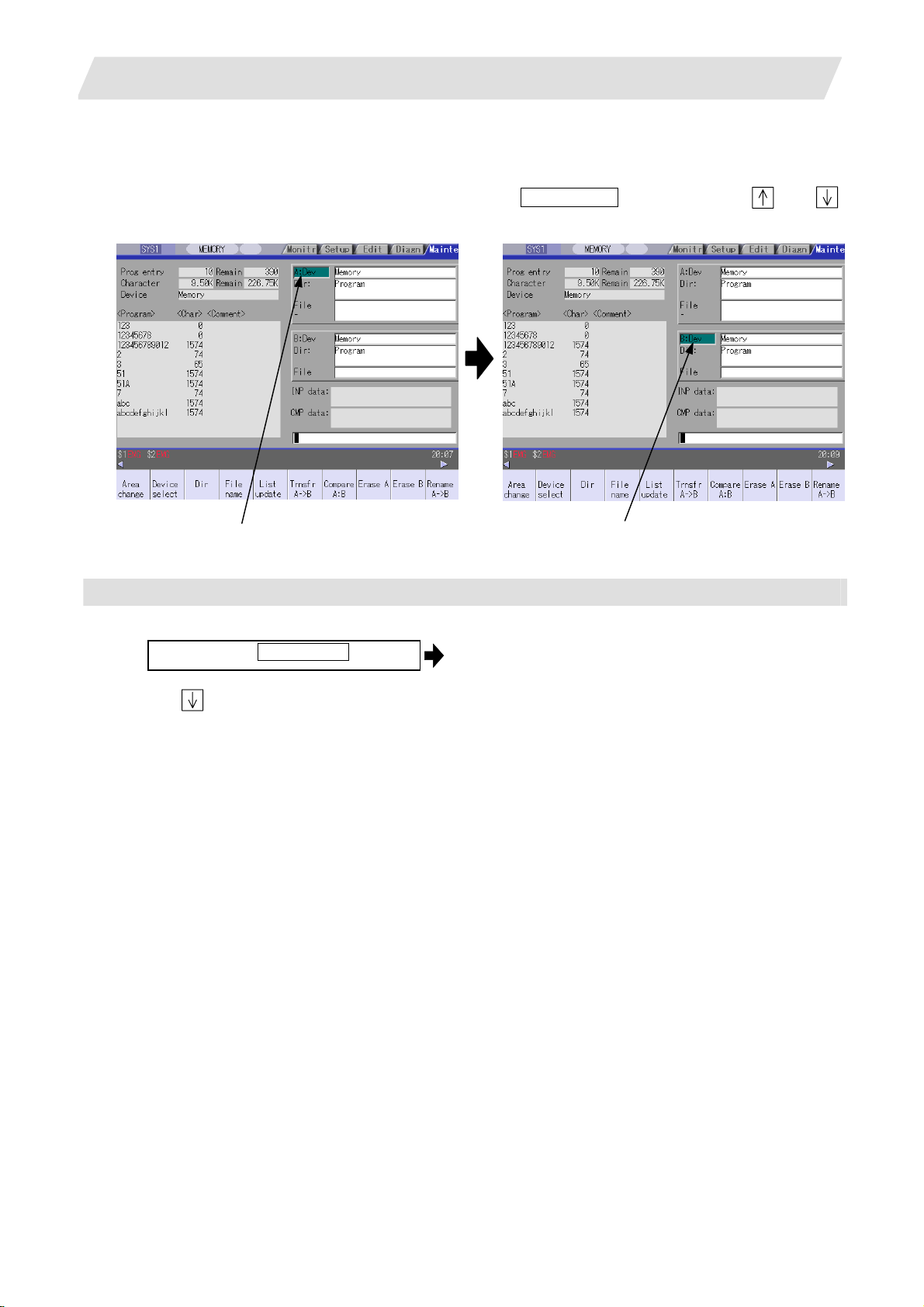
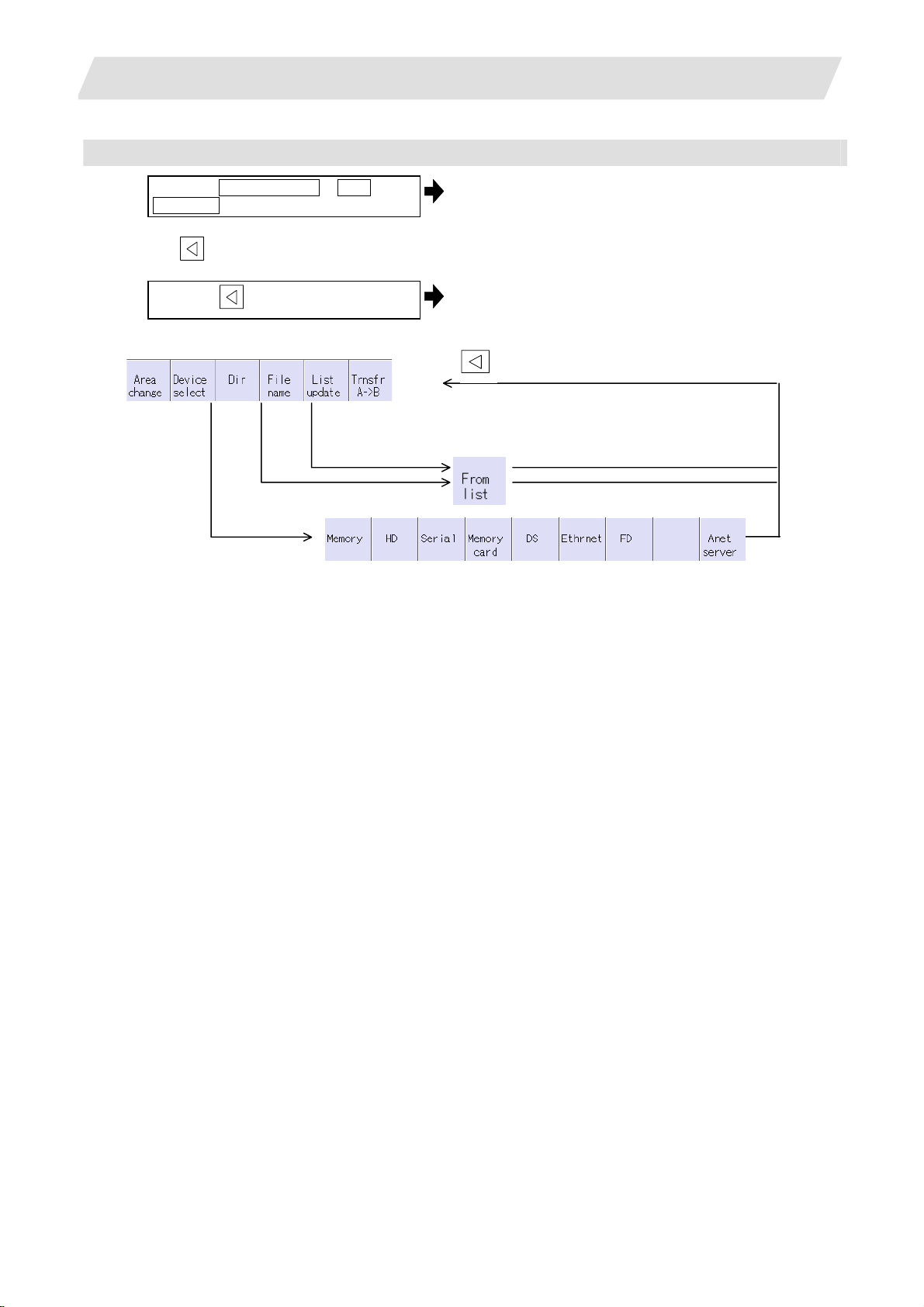
2.1.1 Changing the Valid Area
When setting the file setting field A or B device, directory and file name on this screen, the area containing
these must be valid.
The display area can be changed by pressing the menu key ( Area change ) or the cursor key
After changing, the data setting operation is valid in that area.
and .
File setting field A is valid. File setting field B is valid.
Changing the valid file setting field
When file setting field A (top) is valid
(1)
Press the menu Area change .
This can also be changed with the cursor
key .
The file setting field B (bottom) is validated.
12
Page 23
2. Maintenance Screens
2.1.2 Selecting a Device, Directory and File
File selection sequence
Designate the device where the target file is located.→ Select from the sub menu.
↓
Designate the directory with a full path.
↓
Designate the file name.
Menu used
Device select menu's submenus
Menu Details Type Reference
Memory
HD
Serial
Memory
card
DS
Ethernet
FD
Anet
server
Dir (other than memory) and File name menu submenus
Menu Details Type Reference
From
list
This selects the NC memory (program, parameter, user PLC, NC
data).
This selects the hard disk.
This menu is only for 700 series.
This selects the RS-232C device (PC, tape, etc.). C -
This selects the front IC card. C -
This selects the NC compact flash memory.
This menu is only for 700 series.
This selects the Ethernet-connected host computer. C -
This selects the floppy disk.
This menu is only for 700 series.
This selects the Anshin-net server. C
The cursor appears in the list display. The list contents can be
selected with the INPUT key.
When a directory is selected, the contents of the selected directory
are displayed in the list. Continued selection is possible.
When a file name is selected, the file name is temporarily displayed in
the input area. When the INPUT key is pressed again, it is fixed.
2.1 Input/Output Screen
Input the full path or select from the list.
→
→ Input the file name or select from the list.
C -
C -
C -
C -
A -
13
Page 24
2. Maintenance Screens
Selecting methods for device, directory, and file name
Device Designation target file
NC memory Select from the
Other than the
• Machining program
•
User macro
Fixed cycle
•
machining program
Device Directory File name
submenu
Select from the list
Select from the
submenu
2.1 Input/Output Screen
Designation method
-
(Default)
Key input in the input area,
and press INPUT
Select from the submenu
Key input in the input
area, and press INPUT
-
(Fixed)
Other than the
NC memory
Select from the list Select from the list
All Select from the
submenu
Key input in the input area,
and press INPUT
Key input in the input
area, and press INPUT
The device can be selected from the submenu. (The devices that can be used will differ depending on the
specifications.)
One of the following methods can be used to designate the directory (for devices other than the NC memory)
and file name.
• Set the directory path (full path) or file name in the input area, and press the INPUT key.
• Press submenu From list of the menu Dir or File name . Move the cursor to the target directory or
file name, and press the INPUT key.
A wild card (*) can be used when selecting a file name.
Notes when selecting a file
(1) During directory and file name setting, the designated directory, path or file name will be set, even if it
does not actually exist. This will not cause an error. Note that the previously set directory is overwritten.
(2) Whe n a file in the NC memory other than a machining program is designated, it is not necessary to set the
file name. (The file name is fixed.)
(3) Whe n a file name is selected from the menu, it first is displayed in the input area. However, at this time th e
file name has not yet been fixed. Press the INPUT key again to fix the file name.
(4) When the
key is pressed when setting a file name, the file name in the input area is erased.
(5) When a fixed cycle program is designated, the basic common parameters "#1166 fixpro" must be set.
Select "Memory" for the device, and "Program" for the directory.
14
Page 25
2. Maintenance Screens
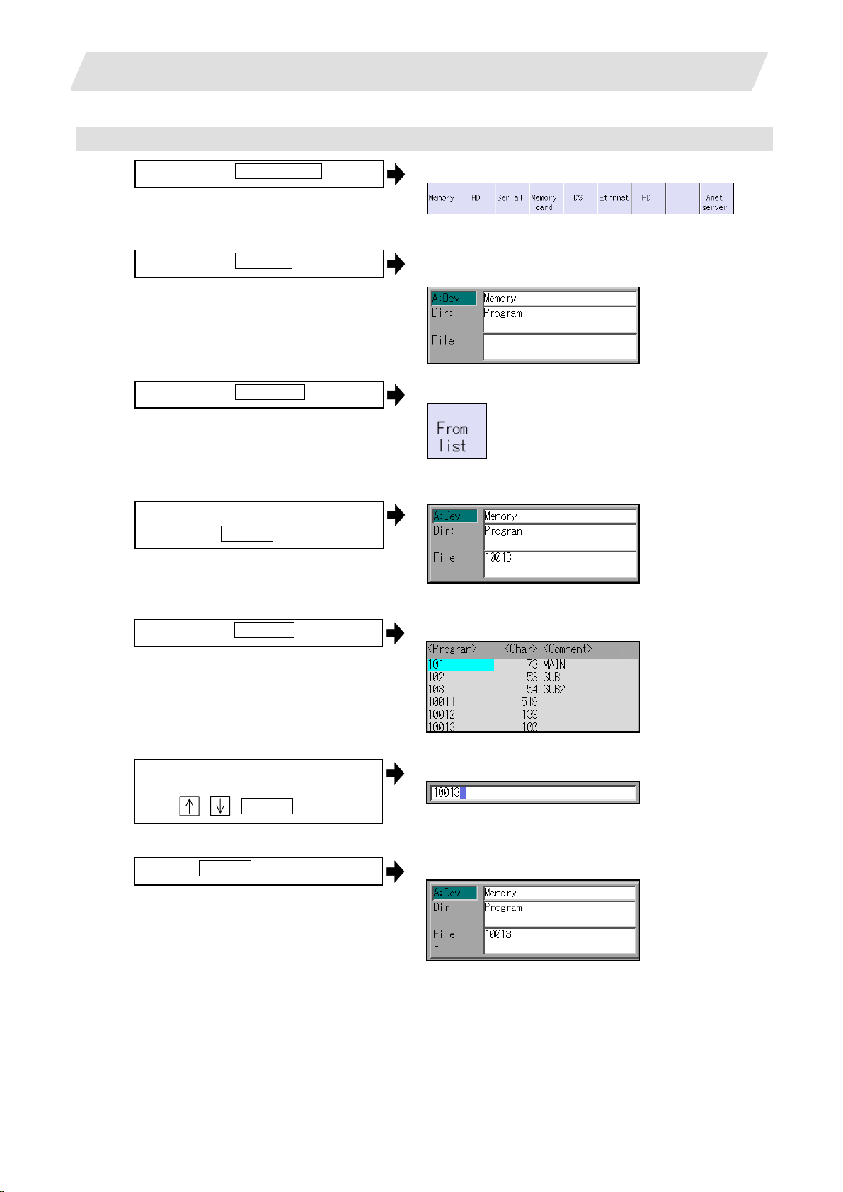
Selecting an NC memory program
(1)
Press the menu Device select .
(2)
Press the menu Memor y .
2.1 Input/Output Screen
The following menu appears.
(When specifications of all devices is valid.)
"Memory" appears in the device name, and the default
"Program" appears in the directory.
(3)
Press the menu File name .
<When inputting the file name from the input area>
(4)
Input the file name
10013 INPUT
<When selecting the file name from the list>
(4)-1
Press the menu From list .
(4)-2 Move the cursor to file name to be
selected, and fix.
, , INPUT
The following menu appears.
The cursor appears in the list.
The selected file name appears in the input area.
(4)-3
Press the INPUT key.
The selected file name appears.
15
Page 26

2. Maintenance Screens
Designating multiple files
(1) Designating multiple serial files
Multiple serial files can be transferred, compared and erased in the file setting column A. Set as follows
in this case.
File : First file name
- : Last file name
(2) Using a wild card
A wild card (* ) can be used in the file name.
(Note) When serial or Anshin-net server is used, multiple files cannot be compared.
:
File
-
*
All files will be selected.
2.1 Input/Output Screen
Selecting an NC memory file other than a program
(1)
Press the menu Device select .
(2)
Press the menu Memor y .
(3)
Select the menu Dir .
(4)
Press the menu Tool offset .
The following menu appears.
(When specifications of all devices is valid.)
"Memory" appears in the device name, and "Program"
appears as the default in the directory.
The following menu appears.
The directory and file name appear.
(Note) The file name for each directory is fixed. Refer to "2.1.6 List of file names" for the file names.
16
Page 27
2. Maintenance Screens
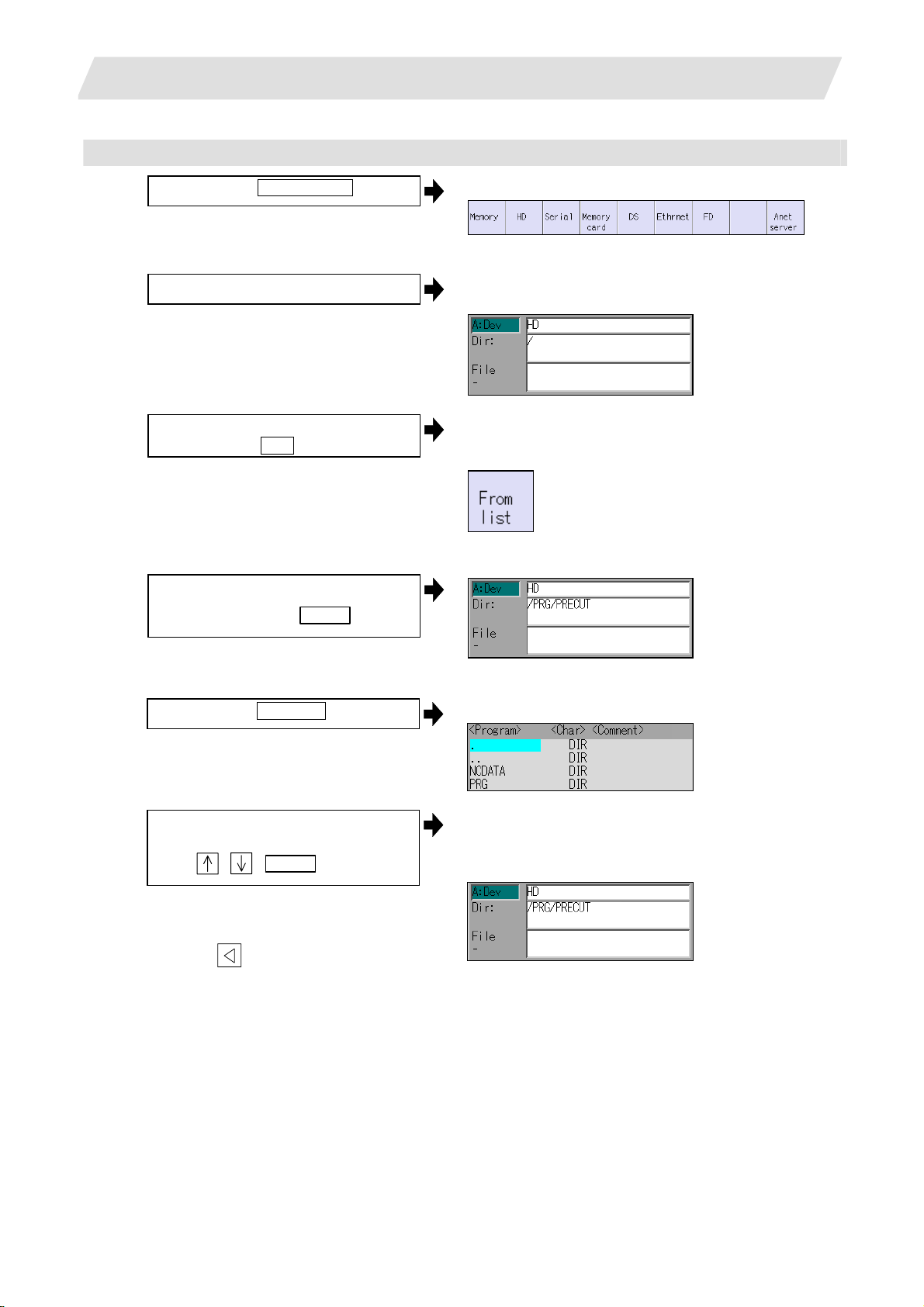
Selecting a device file other than the NC memory
(1)
Press the menu Device select .
(2) Select a device .
2.1 Input/Output Screen
The following menu appears.
(When specifications of all devices is valid.)
The device name appears. The root directory is
selected as the default.
(3)
Designate the directory.
Select the menu Dir
<When inputting the directory from the input area>
(4)
Input the directory path as a full path.
/PRG/PRECUT INPUT
<When selecting the directory from the list >
(4)-1
Press the menu Fr om list
(4)-2 Move the cursor to directory to be
selected, and fix.
, , INPUT
The mode changes to the mode for inputting the
directory name.
The following menu appears.
The cursor appears in the list.
The selected directory appears in the data setting
column.
The contents of the selected directory appear in the
list.
Repeat this operation until the target
directory is reached.
When the target directory is reached,
press the
inputting the directory.
key and quit the mode for
17
Page 28
2. Maintenance Screens
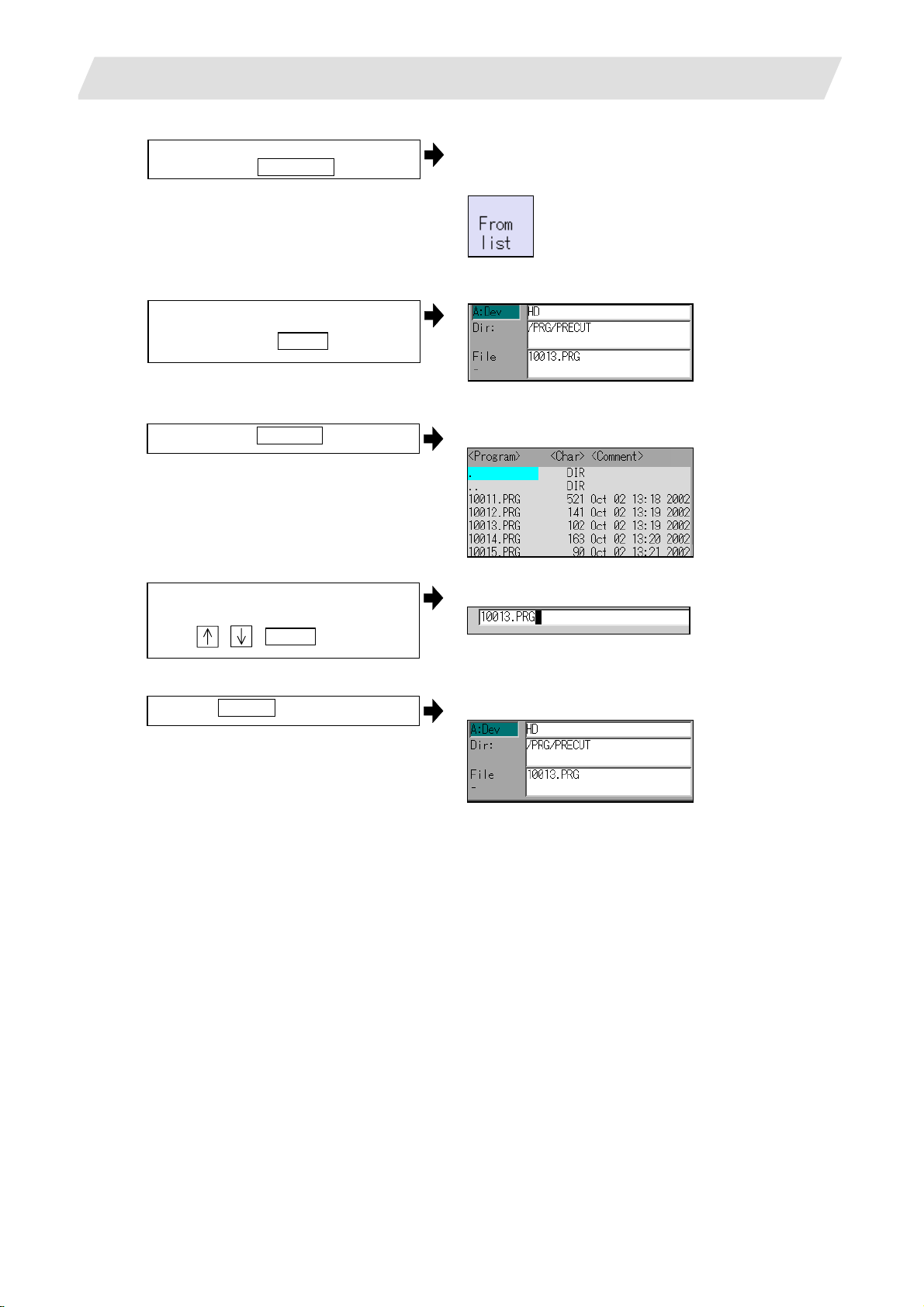
(5) Designate the file n ame.
Press the menu File name
<When inputting the file name from the input area>
(6)
Input the file name
10013.PRG INPUT
2.1 Input/Output Screen
The mode changes to the mode for inputting the file
name.
The following menu appears.
<When selecting the file name from the list>
(6)-1
Press the menu From list .
(6)-2 Move the cursor to file name to be
selected, and fix.
, , INPUT
(6)-3
Press the INPUT key.
The cursor appears in the list.
The selected file name appears in the input area.
The selected file name appears.
18
Page 29
2. Maintenance Screens
Canceling the input mode
(1)
Press the Device Select , Dir or
File name .
To cancel the data input at this time, press
the key.
(2)
Press the
Main menu
key.
2.1 Input/Output Screen
The submenu appears.
The details in the input area are erased, and the main
menu appears.
The details in the data input area are erased.
Submenu
(When specifications of all devices is valid.)
19
Page 30
2. Maintenance Screens
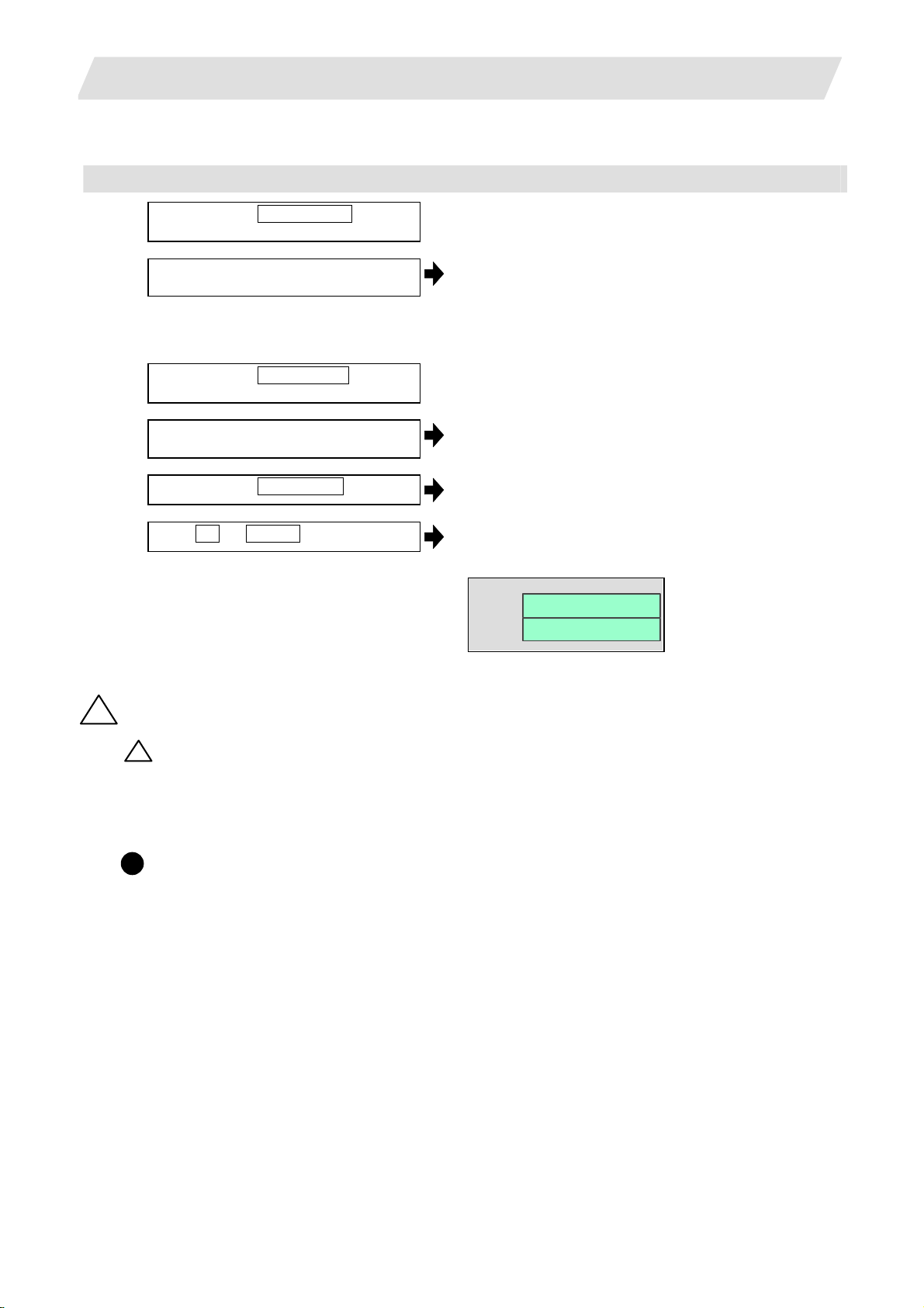
2.1.3 Transferring a File
Operating method
(1)
Press the menu Area change , and
select file setting column A.
(2) Designate the transfer origin device,
directory and file name.
(3)
Press the menu Area ch ange , and
select file setting column B.
(4) Designate the transfer destination device,
directory and file name.
(5)
Press the menu Trnsfr A ->B .
(6)
Press Y or INPUT .
2.1 Input/Output Screen
The designated file appears.
Multiple files can be designated in the file setting
column A. Designate the first and last file name of the
target range. A wildcard "*" can be designated for the
file name.
The designated file appears.
A message appears to confirm the transfer.
The file transfer starts. The data being transferred
appears in the input data display column.
A message appears when the transfer is completed.
INP data :
CMP data :
Caution
!
" ; ", "EOB", "%", and “EOR” are symbols used for explanation. The actual codes for ISO are "CR, LF" ("LF")
!
and "%".
The programs created on the Edit screen are stored in the NC mem ory in a "CR, LF" format, however, the
programs created with external devices such as the FD or RS-232C may be stored in an "LF" format.
The actual codes for EIA are "EOB (End of Block)" and "EOR (End of Record)".
G91 G28 XYZ;
F1000;
!
To prevent the influence of data loss and data transformation over the line, always carry out data
comparison after transferring a machining program.
20
Page 31

2. Maintenance Screens
Notes
(1) Notes related to transferring in general
(a) Depending on the type of file, some data cannot be transferred during automatic operation. Do not
transfer during automatic operation.
(b) When the capacity of the transfer destination is reached during file transfer, only the data transferred
up to that point is registered as a file, and an error will result.
(c) During input to the NC memory or comparison, if the file format size on the NC memory side differs
from the other side file format size (when the maximum number of registrations differs between the
NC memory and the other side), processing is carried out matched to the small er size.
(Ex. 1) If a format size of 200 files is input for a format size of 1000 NC files, 200 files are registered.
(Ex. 2) If a format size of1000 files is input for a format size of 200 NC files, the files up to the 200th
file are registered and an error message appears. (The remaining files are not registered.)
(d) Up to 223 files, including the directory, can be registered in the FD's root directory.
(2) Notes when transferring machining program files
(a) For the serial, always set feed (Null) at both ends of the "EOR" code at the head and end. If "EOB"
etc., is directly after "EOR", the operation may not execute normally due to the input buffer influence
during the next input operation.
(b) The transfer speed is slower if there are many registrations.
(c) The size of one block of the machining program should be 250 characters or less.
(d) When using tape, carry out parity V adjustment to improve the reliability of the tape format. Then use
with the input/output parameter "Parity V" validated.
(e) When the machine tool builder macro and fixed cycle program are input to NC memory, change the
program type with the parameter "#1166 fixpro". Also, set in the Input/Output screen as follows.
Device: Memory, Directory: Program
(f) Transferring or verifying the multiple files between the external device connected serially and that
other than the serial connection.
(g) With machining program created before the MELDAS500 Series, "EOB" is registered as "LF".
However, wh en these programs are stored in the 700/70 Series NC memory, "EOB" will be converted
to "CR LF", and the number of characters will increase. Thus, when all of the machining programs
output from an MELDAS500 Series or earlier NC, having the same specifications as the maximum
memory capacity, are stored in the 700/70 Series NC memory, the memory capacity may be
exceeded.
(h) When the file to be transferred (input) is running or in "program restarting" mode, the operation
message "Executing automatic operation" or "Program restarting" is displayed and file will not be
transferred (input).
(3) Notes when transferring tool offset data files
(a) If an error occurs during offset data transfer, an error message appears on the screen, and the
transfer operation is interrupted.
(4) Notes when transferring parameter files
(a) In the same manner as when setting in the Parameter screen, there are parameters validated
immediately after input, and parameters validated after a restart. Restart when a parameter file has
been transferred to the NC memory.
(b) When a parameter file is transferred to the NC memory, the setting value of the input/output
parameters is also changed. Before transferring next time, set the input/output parameters again.
(c) System parameters can be transferred from the NC memory to an external device, but cannot be
transferred from an external device to the NC memory.
2.1 Input/Output Screen
21
Page 32

2. Maintenance Screens
(5) Notes when transferring common variable data files
(a) If the variable value is 100000 or more or less than 0.0001 when transferring common variable data,
it is expressed with an exponential expression.
(6) Notes when transferring tool life data files
(a) When tool life data is output from the NC memory, the file information is inserted at the first and last
of the file.
First file information : Number of registered tools (P No.) and the maximum number of possible
registrations (T No.)
Last file information : Finish code
(7) Notes when transferring auxiliary axis parameter files (700 series only)
(a) When the auxiliary axis parameters are input to the NC memory, the same parameter data is
simultaneously transferred to the drive unit. If transferred errors by some causes occur, the
parameter data may be not matched between NC memory data and drive unit.
(8) Notes when transferring sampling data file
(a) When the output form is set as 8-digit hexadecimal number and the parameter
"#1004 ctrlunit" is set to "E (1nm)", accurate data can be output just within 1m.
When the output data length exceeds 1m, lower 32 bits of the sampling data will be output.
2.1.4 Comparing Files (Compare)
Operation method
(1)
Press the menu Area change , and
select file setting column A.
(2) Designate the device, directory and file
name to be compared.
(3)
Press the menu Area change , and
select file setting column B.
(4) Designate the other side device, directory
and file name to be compared.
(5)
Press the menu Compare A:B .
The designated file name appears.
The designated file name appears.
The file comparison starts. The data being compared
appears in the comparison data display column.
A message appears when the comparison is
completed.
If a comparison error occurs, the block with the error is
displayed in the comparison data display column on
the screen.
2.1 Input/Output Screen
(Note) Files that can be compared are text files only.
Correct outcome will not be obtained through binary file comparison.
22
Page 33

2. Maintenance Screens
2.1 Input/Output Screen
2.1.5 Formatting an External Device
Operation method (Formatting an FD) [700 series only]
(1) Insert a floppy disk in the FD drive, and
press FD format .
(2)
Press Y or INPUT .
A message confirming the formatting appears.
The FD is formatted.
A message appears when the formatting is completed.
(Note 1) The FD is formatted with FAT (1.44MB).
(Note 2) The volume label is set when formatting the FD.
Operation method (Formatting a memory card)
(1)
Press the menu MemCrd format .
(2)
Press Y or INPUT .
A message confirming the formatting appears.
The memory card is formatted.
A message appears when the formatting is completed.
(Note 1) The memory card is formatted with FAT16.
(Note 2) The volume label is set when the memory card is formatted.
Operation method (Formatting a DS) [700 series only]
First, press the menu DS format . Refer to "Formatting a memory card" for following operations.
(Note 1) The DS is formatted with FAT16.
(Note 2) Only the DS formatted with FAT16 can be used. The DS with NTF S cannot be used.
(Note 3) As for the DS formatted with NTFS, reformat it with FAT formatted by Windows to use.
(NC cannot convert NTFS partition to FAT formatted.)
(Note 4) The volume label is not set even when the DS is formatted.
2.1.6 List of File Names
There is a directory for each type of data in the NC memory.
Each directory and file name (fixed) in the NC memory is shown below.
Do not change the extensions (.XXX) when storing in a device other than the NC memory.
Data type NC memory directory path Fixed file name
Machining program /PRG/USER (Program No.)
Fixed cycle program /PRG/FIX (Program No.)
Parameters
Parameters [User, machine] (Text format)
Auxiliary axis parameter (700 series only)
User PLC /LAD USERPLC.LAD
NC data
Tool compensation amount data
Tool life management data
Common variable data
SRAM data
System configuration data /DGN ASSEMBLY.INF
Decryption code /RLS P ASSCODE. DAT
Sampling data /LOG NCSAMP.CSV
Machine data /DGN COMPO.STA
/PRM
ALL.PRM
AUXAXIS.PRM
/DAT
TOOL.OFS
TLIFE.TLF
COMMON.VAR
SRAM.BIN
23
Page 34

2. Maintenance Screen
2.2 All Backup Screen
2.2 All Backup Screen
This screen is used to perform batch backups of NC memory data to an external device, and batch
restoration of that data to the NC memory.
Data backed up by the automatic backup function can also be restored.
Data which has been automatically backed up can be selected only when the device set by the "#8919 Auto
backup device" parameter setting is selected.
(1)
(2)
Display items
(3)
(5)
Display item Details
(1) Device name This displa ys the selected device name.
(2) Data name This displays the data name being backed up/restored.
System data, ladder, and APLC data are displayed.
(3) Execution status This displays the processing execution status.
Processing is executed in the system data, ladder, and APLC data order.
(Note 1)
(4) Warning message T his displays messages at the start and end of backup/restore processing.
(5) Backup list This displays the backup date list.
This date is the system data time stamp.
Backup area Explanation
Auto 1
2
3
Data that was automatically backed
up. Display in the backup date
descending order. The latest three
generations of data are displayed.
(4)
Backup
format
Auto
Manual Data that was backed up on this
screen.
Master data Data that was backed up on this
screen. Generally, this is the factory
settings data.
The above data can be selected at restore processing. (Note 2)
Manual
Manual
(Note 1) "APLC data" cannot be backed up/restored if the optional "APLC" is disabled.
(Note 2) The "Auto 1 to 3" data display when the device set by the "#8919 Auto backup device" parameter is
selected.
24
Page 35

2. Maintenance Screen
Menus
Menu Detail Type Reference
Device
select
Backup
Restore
Stop
2.2 All Backup Screen
This displays the sub-menu for "Device" selection. C
This executes backup processing. A 2.2.1 Performing a
This executes restore processing. A 2.2.2 Performing a
This stops processing. C
Backup Operation
Restore Operation
25
Page 36

2. Maintenance Screen
2.2.1 Performing a Backup Operation
Operation methods
(1)
Press the menu Backup .
(2) Move the cursor to select the area.
Press the INPUT key.
(3)
Press Y or INPUT key.
2.2.2 Performing a Restore Operation
Operation methods
(1)
Press the menu Restore .
(2) Move the cursor to select the file.
Press the INPUT key.
(3)
Press Y or INPUT key.
2.2 All Backup Screen
The menu is highlighted.
An operation message "Select directory to
backup" appears.
An operation message "OK? (Y/N)" appears.
(Note) Auto 1 to 3 cannot be selected.
Backup operation begins.
An operation message "Backupping" appears.
When the backup is completed without error, an
operation message "Backup complete" appears.
The menu is highlighted.
An operation message "Select directory to
restore" appears.
An operation message "OK? (Y/N)" appears.
Restore operation begins.
An operation message "Restoring" appears.
When the restoration is completed without error,
an operation message "Restore complete"
appears.
26
Page 37

2. Maintenance Screen
2.2 All Backup Screen
2.2.3 Setting Automatic Backup
When you validate automatic back up function, NC memory data can be backed up automatically.
(1) Parameter setting
By setting the below parameters on operation parameter screen, the automatic back up function will be
validated.
# Item Contents Setting range (unit)
8915 Auto backup day 1
8916 Auto backup day 2
8917 Auto backup day 3
8918 Auto backup day 4
8919 Auto backup device This sets the automatic backup target device. 0: DS
When the NC power is ON after the designated
date was passed over, the automatic backup is
executed.
When -1 is set to "Auto backup day 1", the
automatic backup is executed every turning NC
power ON.
When 0 is set to all on "Auto backup day 1" to "4",
the automatic backup is not executed. It is possible
to specify the designated date up to 4 days for a
month.
-1 to 31
(-1 can be set for "Auto
backup day 1" only.)
1: HD
2: Memory card
(1)
(2)
(3)
(5)
(4)
(5) Backup list This displays the backup date list.
This date is the system data time stamp.
Backup area Explanation
Auto 1
2
3
Data that was automatically backed
up. Display in the backup date
descending order. The latest three
generations of data are displayed.
Backup
format
Auto
27
Page 38

2. Maintenance Screen
2.2.4 Backing up the SRAM
(1)
Press the menu SRAM backup .
(2)
Press Y or INPUT .
Press a key other than Y or
INPUT to cancel the backup.
2.2 All Backup Screen
A message appears to confirm the backup execution.
The backup is executed.
<700 series>
The data is backed up into "D:¥ NCFILE ¥ SRAM.BIN"
on the HD.
(If SRAM.BIN already exists, the original file will be
saved as SRAM.BAK.)
<70 series>
The data is backed up into the memory card.
28
Page 39

2. Maintenance Screen
Menus
Menu Details Type Reference
Psswd
input
PLC
stop
All
backup
System
setup
Adjust
S-ana
To
Abs pos
AUX
test
Collect
set
Format
T-life
format
Serial
No.Set
Console
exec
To
In/out
To
param
SRAM
backup
HMI
Quit
This changes the screen related to the maintenance by setting the
password.
This forcible stops the PLC ladder process. If this menu key is pressed
in the stopped state, the stop is canceled.
This backs up (saves) or restores (reloads) the file such as SRAM etc.
to designated device.
This automatically executes necessary parameter setting for driving
servomotor only by setting necessary minimum item.
This changes the screen to that for adjusting the spindle analog
output.
This sets the absolute position for servo axis (arbitrary NC axis, PLC
axis).
This carries out absolute position setting or test operation by the
auxiliary axis forward run/reverse run.
This menu is only for 700 series.
This executes the followings.
Setting to collect the diagnosis data
Confirming the diagnosis data collection status
Starting/Stopping to collect the diagnosis data
Clearing the diagnosis data
This formats the NC memory. B
This formats the tool life management data. B
This changes the NC serial No. A
The console is executed. The MS-DOS window will appear. C
This changes the screen to the Data Input/Output screen. C
This changes the screen to the Parameter screen. C
<700 series>
This backs up the NC SRAM information on the HD.
<70 series>
This backs up the NC SRAM information on the memory card.
This quits the screen operation. B
2.2 All Backup Screen
A
C
C
C
C
C
C
C
B
29
Page 40

2. Maintenanace Screens
2.3 Absolute Position Setting Screen
2.3 Absolute Position Setting Screen
The Absolute position setting screen is used to set the data for the absolute position of servo axes including
arbitrary NC axes and PLC axes.
(1)
(8)
(7)
(2)
(3)
(4)
(5)
(6)
Display items
Display item Details
(1) Axis name This displays the axis name set with the parameter "#1022 axname2".
The axis name can be switched by Axis select, Next axis, or Prev axis.
(2) Type of zero point
initialization
Progress state
(3)
State
Machine end This displays the distance from the mechanical basic position to the first grid point.
Machine posn This displays the current machine position. "Not passed" will appear until the axis
(4) Data No.
(5) Name
(6) Data
This displays the type of zero point initialisation for the selected axis.
The shortened expression of the zero point initialization method selected with the
parameter “#2049 type (type of absolute position detection system)”.
Displayed
expression
1 Inc. Incremental position detection system Other
2 With Stopper Machine end stopper
3 Marked point alignment
No Stopper
4
5 Dog-type Dog-type absolute position detection system 3
This displays the progress state of zero point initialisation. (Note)
passes a grid point for the first time.
This displays the No., name, and data used to establish the absolute position.
Dogless-type
absolute position
detection system
Type of zero point initialization
for absolute position
method
method
Marked point alignment
method II
• 0 to 2 : Internal data
• 2050 to 2059 : Absolute position parameters
These can be set also in Absolute position parameter screen.
Refer to "Setup Manual" for explanation and setting range of the parameters #2050 to
#2059.
Setting
value
than
1,2,3,4,
1
2
4
30
Page 41

2. Maintenanace Screens
2.3 Absolute Position Setting Screen
Display items Details
(7) Procedures This shows the procedures to establish the coordinate system by zero point
initialization. The contents differ depending on the type of zero point initialisation.
(8) Initialization message This displays a message with the background yellow if an illegal value has been set
for the zero point initialization. Refer to the section "10. Appendix" for details.
(Note) [T ype of zero point initialization] indicates the progress stat e of zero point initialization as shown below.
1.Dogless-type absolute position detection system
Machine end stopper method (manual initialization)
Order Display Details of progress
1 Illegality While the absolute position is lost.
2 Stopper From when the menu "Abs pos set" is pressed
to when the axis pushes against the machine end stopper.
3 Release From when the axis pushes against the machine end stopper
to when axis starts to move in the counter direction.
4 Ret. Ref. P. From when the axis moves in the counter direction
to when it reaches the grid point immediately before the stopper.
5 Complete The axis has reached the grid point immediately before the stopper.
The absolute position has been established.
2. Dogless-type absolute position detection system
Machine end stopper method (automatic initialization)
Order Display Details of progress
1 Illegality While the absolute position is lost.
2 Jog Start From when the menu "Abs pos set" is pressed
to when a value is set in "Zero-P".
3 Stopper1 From when JOG operation starts
to when the axis pushes against the machine end stopper.
4 Zero-P. Rel. From when the axis pushes against the machine end stopper
to when axis reaches the approach point.
5 Stopper2 From when the axis reaches the grid point immediately before the stopper
to when it pushes against the machine end stopper.
6 Ret. Ref. P. From when the axis pushes against the machine end stopper second time
to when axis reaches the grid point immediately before the stopper.
7 Complete The axis has reached the grid point immediately before the stopper.
The absolute position has been established.
3. Dogless-type absolute position detection system
Marked point alignment method
Order Display Details of progress
1 Illegality While the absolute position is lost.
2 Origin Set From when the menu "Abs pos set" is pressed
to when "1" is set in "Origin-P".
3 Ret. Ref. P. While moving in the direction designated with the abs olute position parameter #2050.
4 Complete The axis has reached the grid point immediately before the marked point.
The absolute position has been established.
4. Dogless-type absolute position detection system
Marked point alignment method II
Order Display Details of progress
1 Illegality While the absolute position is lost.
2 Origin Set From when the menu "Abs pos set" is pressed
to when "1" is set in "Origin-P".
3 Complete With the sequence ab ove, the absolute position is established.
5. Dog-type absolute position detection system
Order Display Details of progress
1 Illegality While the absolute position is lost.
2 Zero-P. Rel. After dog-type manual or automatic reference position return is started.
3 Complete Axis has returned to the reference position.
31
Page 42

2. Maintenanace Screens
Menus
Menu Details Type Reference
Axis
select
Prev
axis
Next
axis
After selecting this menu, set the axis name, and press the INPUT key
to display the axis name and related data.
This switches the data display to the previous axis' data
When the first data is displayed, the last axis data will be displayed.
This switches the data display to the next axis' data
When the last data is displayed, the first axis data will be displayed.
2.3.1 Selecting the Axis
Procedures
(1)
Press the menu Axis select .
(2) Set the axis name (which was set with
"#1022 axname2") and press INPUT key.
2.3 Absolute Position Setting Screen
A 2.3.1 Selecting an Axis
A
C
The menu is highlighted.
The cursor appears in the input area.
The axis name and data change.
Procedures displays according to the selected initialization
type.
32
Page 43

2. Maintenanace Screens
2.3.2 Carrying Out Dogless-type Zero Point Initialization
Procedures (Machine end stopper method : manual method)
Set the following parameter beforehand in the "Abs.Posit.Param." screen.
Parameter Setting value
#2049 type (absolute position detection type) 1 (machine end stopper method is selected)
#2054 clpush (current limit) 0 to 100
#2059 zerbas (zero point return parameter) 1 (on the grid point immediately before the stopper)
The parameters other than "#2049 type" can be set in the "Zero point set" screen.
(1) Select the axis that "#2049 type" is "1".
(2) Select the HANDLE mo de or JOG mode.
(3) Input "1" to "Absolute posn set".
(4) Input an arbitra ry value to "#2 Zero-P".
(5) Move the axis toward the machine end
stopper.
-> a
(6) Hit against the machine end stopper.
-> b
The current has reached its limit for given
time.
-> c
(7) Move the axis in the counter direction.
-> d
The axis has reached the grid point
immediately before the stopper.
-> e
This completes zero poi nt initializati on. Turn the power OFF
Refer to "2.3.1 Selecting the Axis" for procedures to select
the axis.
The input value appears at "Absolute posn set".
The input value appears at "#2 Zero-P".
State : [Stopper]
Machine end : Distance between stopper and grid point
Machine posn : [Not passed] -> current machine position
State : [Stopper]
State : [Release]
State : [Ret. Ref. P.]
State : [Complete]
and ON after the initialization for all axes.
2.3 Absolute Position Setting Screen
33
Page 44

2. Maintenanace Screens
If "#2059 zerbas" is "0" (absolute position origin point = mechanical basic position), axis will stop
automatically at this point without moving in the opposite direction and "Complete" appears at [ State] and
"0.000" at [Machine end].
Initialization start point
2.3 Absolute Position Setting Screen
(5)
(6)
Basic machine coordinate system
zero point
Zero return parameter
"#2037 G53ofs"
"#2 Zero-P" depends on the setting of "#2059 zerbas".
Reference
position
Grid point
(electric basic
position)
"#2 Zero-P" (#2059 zerbas=1)
"#2 Zero-P" (#2059 zerbas=0)
(8)
(9)
"Machine end"
(7)
Machine end stopper
(Mechanical basic
position)
(Note1) To change just the basic machine coordinate zero point, set "#0 Absolute posn set" and "#2 Zero-P",
and then turn the power OFF and ON.
(Note2) If pressing against the machine end is attempted without passing the grip point once after turning
the power ON, the operation message "Not passed on grid" will appear. Return to a point before the
last grid, and then repeat from step of pressing against the machine end stopper.
(Note3) If the first grid point is covered by the grid mask (#2028 grmask) as a result of return to the electric
basic position, the axis stops at the next grid point.
Note that zero-point shift amount (#2027 G28sft) is invalid.
34
Page 45

2. Maintenanace Screens
Procedures (Machine end stopper method : automatic method)
Set the following parameter beforehand in the "Abs.Posit.Param." screen.
Parameter Setting value
#2049 type (absolute position detection type) 1 (machine end stopper method is selected)
#2054 clpush (current limit) 0 to 100
#2055 pushf (push speed) 1 to 999
#2056 aproch (approach point) 0 to 999.999
#2059 zerbas (zero point return parameter) 1 (on the grid point immediately before the stopper)
The parameters other than "#2049 type" can be set in the "Zero point set" screen.
(1) Select the axis that "#2049 type" is "1".
(2) Select the "Auto init set" mode.
(3) Input "1" to "Absolute posn set".
(4) Input an arbitra ry value to "#2 Zero-P".
The axis moves toward the machine end
stopper at the push speed (#2055).
-> a
The axis pushes against the machine end
stopper. After the current reached its limit
for given time, the axis returns toward the
approach point at the "push speed".
-> b
After arrived at the approach point, the
axis moves toward the machine end
stopper at the "push speed".
-> c
The axis pushes against the machine end
stopper. After the current reached its limit
for given time, the axis returns toward the
grid point immediately before the stopper
at the "push speed".
-> d
immediately before the stopper.
-> e
This completes zero poi nt initializati on. Turn the power OFF
Refer to "2.3.1 Selecting the Axis" for procedures to select
the axis.
The input value appears at "Absolute posn set".
The input value appears at "#2 Zero-P".
State : [Stopper1] (5) Start JOG operation.
Machine posn : [Not passed] -> current machine position
State : [Stopper1]
State : [Zero-P. Rel.]
State : [Stopper2]
State : [Ret. Ref. P.]
State : [Complete] The axis has reached the grid point
Machine end : Distance between stopper and grid point
and ON after the initialization for all axes.
2.3 Absolute Position Setting Screen
35
Page 46

2. Maintenanace Screens
If "#2059 zerbas" is "0" (absolute position origin point = mechanical basic position), axis will stop
automatically at this point without moving in the opposite direction and "Complete" appears at [S t ate] and
"0.000" at [Machine end].
Basic machine coordinate system
zero p o in t
2.3 Absolute Position Setting Screen
Initializa tio n s ta rt point
Reference
position
Reference position
parameter
"#2037 G53ofs"
"#2 Ze ro -P " (# 2 0 59 zerba s = 1 )
"#2 Zero-P" (#2059 zerbas=0)
"#2 Zero-P" depends on the setting of "#2059 zerbas".
Push speed
Grid p o in t
(electric basic
position)
"#2056 aproch"
a
b
e
"Machine end"
c
d
Machine end stopper
(mechanical basic
position)
(Note1) To change just the basic machine coordinate zero point, set "#0 Absolute posn set" and "#2 Zero-P",
and then turn the power OFF and ON.
(Note2) If pressing against the machine end is attempted without passing the grip point once after turning
the power ON, the operation message "Not passed on grid" will appear. Return to a point before the
last grid, and then repeat from step of pressing against the machine end stopper.
(Note3) If the first grid point is covered by the grid mask (#2028 grmask) as a result of return to the electric
basic position, the axis stops at the next grid point.
Note that zero-point shift amount (#2027 G28sft) is invalid.
(Note4) Acceleration/deceleration during movement at the specified push speed is performed in
smoothing-off (step feed) mode.
(Note5) If "0" is specified for "#2056 aproch" of the absolute position parameters, the machine zero point is
regarded as the approach point.
(Note6) Automatic initialization is interrupted if one of the following events occurs. If it is interrupted, [State]
indicates "Jog Start" (after selecting the "Auto init set" mode if it is caused by mode change), so
restart operation from the step of JOG-start.
• An absolute position detection alarm occurs.
• Operation preparation signal turns OFF.
• The mode is changed.
• The system is reset.
If [State] is "Complete" before automatic initialization is started, "State" returns to "Complete" when
power is turned OFF and ON again without restarting the operation.
36
Page 47

2. Maintenanace Screens
2.3 Absolute Position Setting Screen
(Note7) Automatic initialization cannot be started in the following cases. The operation message "Can't
start" will appear if starting is attempted.
• When "#0 Absolute posn set" is not set.
• When the "#2 Zero-P" setting is inappropriate.
• When "#2055 pushf" is not set.
• When "Z71 Abs encoder failure 0005" has oc curred.
In the above cases, if the "#2 Zero-P" setting is inappropriate, this means that the relation of "#2
Zero-P" and "#2037 G53ofs" is inappropriate. That is, if "#2 Zero-P" is smaller than the "#2037
G53ofs", the machine end stopper will be located betwee n the basic ma chin e coordin ate sy stem ze ro
point and reference position; this disables automatic initialization. (Refer to the following left figure.)
If "#2 Zero-P " is set to "0", the machine end stopper direction is unpredi ctable; this also disables
automatic initialization. (Refer to the following right figure.)
Basic machine coordinate
system zero point
Machine end stopper
(Mechanical basic
"#2 Zero-P"
#2037 "G53ofs"
Looking from the basic machine coordinate system zero point,
the reference position is located far beyond the machine end
stopper, thus the reference position return cannot be carried out.
position)
Reference
position
If the "#2 Zero-P" setting is "0", the basic
machine coordinate system zero point is
located on the machine end stopper.
The direction of axis movement is thus
unpredictable.
Machine end stopper
(Mechanical basic
position)
Basic machine coordinate
system zero point
37
Page 48

2. Maintenanace Screens
Procedures (Marked point alignment method)
Set the following parameter beforehand in the "Abs.Posit.Param." screen.
Parameter Setting value
#2049 type (absolute position detection type) 2 (marked point alignment method is selected)
#2050 absdir (basic Z - direction) 0/1
The parameters can be set in the "Zero point set" screen.
(1) Select the axis that "#2049 type" is "2".
(2) Select the HANDLE mode, HANDLE-AX
mode, or JOG mode.
(3) Input "1" to "#0 Absolute posn set".
(4) Input an arbitra ry value to "#2 Zero-P".
basic position and align it to the marked
point.
-> a
(6) Input "1" to "#1 Origin-P".
with the parameter "#2050 absdir".
-> b
The axis reaches the first grid point.
-> c
This completes zero poi nt initializati on. Turn the power OFF
2.3 Absolute Position Setting Screen
Refer to "2.3.1 Selecting the Axis" for procedures to select
the axis.
The input value appears at "#0 Absolute posn set".
The input value appears at "#2 Zero-P".
State : [Origin Set] (5) Move the axis toward the mechanical
Machine posn : [Not passed] -> current machine position
The input value appears at "#1 Origin-P".
State : [Ret. Ref. P.] (7) Move the axis in the direction designated
Machine end : Distance between machine basic point
(marked point) and the first grid point
State : [Complete]
and ON after the initialization for all axes.
38
Page 49

2. Maintenanace Screens
2.3 Absolute Position Setting Screen
Initialization start point
Basic machine
coordinate system
zero point
Zero point parameter
"#2037 G53ofs"
#2 Zero-P (#2059 zerbas=1)
#2 Zero-P (#2059 zerbas=0)
Reference
position
(electric basic
(Note 1) To change just the basic machine coordinate zero point, set "#0 Absolute posn set" and "#2 Zero-P",
and then turn the power OFF and ON.
(Note 2) If aligning axis on the marked point is attempted without passing the grip point once after turning the
power ON, the operation message "Not passed on grid" will appear. Return to a point before the last
grid, and then repeat from step of aligning the axis on the marked point.
(Note 3) If the first grid point is covered by the grid mask (#2028 grmask) as a result of return to the electric
basic position, the axis stops at the next grid point.
Note that zero-point shift amount (#2027 G28sft) is invalid.
(Note 4) Reconfirm the "absdir" setting if the machine does not move in the direction of "#2050 absdir". The
machine will move only in the positive direction when set to “0”, and the n egative direction when set
to "1".
a
Grid point
position)
c
"Machine end"
b
Machine end
stopper
(Mechanical basic
position)
39
Page 50

2. Maintenanace Screens
Procedures (Marked point alignment method II)
Set the following parameter beforehand in the "Abs.Posit.Param." screen.
Parameter Setting value
#2049 type (absolute position detection type) 4 (marked point alignment method II is selected)
The parameters other than "#2049 type" can be set in the "Zero point set" screen.
(1) Select the axis that "#2049 type" is "4".
(2) Select the HANDLE mode, HANDLE
FEED AXIS SELECT mode, or JOG mode.
(3) Input "1" to "#0 Absolute posn set".
(4) Input an arbitra ry value to "#2 Zero-P".
Move the axis toward the mechanical
basic position and align it to the marked
point.
-> a
Input "1" to "#1 Origin-P".
2.3 Absolute Position Setting Screen
Refer to "2.3.1 Selecting the Axis" for procedures to select
the axis.
The input value appears at "#0 Absolute posn set".
The input value appears at "#2 Zero-P".
State : [Origin Set]
The input value appears at "#1 Origin-P".
State : [Complete]
Machine end : 0.000
Machine posn : The value set in "#2 ZERO"
Initialization start point
Basic machine
coordinate system
zero point
Reference position
parameter
"#2037 G53ofs"
Reference
position
a
Machine end
stopper
(mechanical
basic position)
(Note1) To change just the basic machine coordinate zero point, set "#0 Absolute posn set" and "#2 Zero-P",
and then turn the power OFF and ON.
(Note2) If aligning axis on the marked point is attempted without passing the grip point once after turning the
power ON, the operation message "Not passed on grid" will appear. Return to a point before the last
grid, and then repeat from step of aligning the axis on the marked point.
(Note3) If the first grid point is covered by the grid mask (#2028 grmask) as a result of return to the electric
basic position, the axis stops at the next grid point.
Note that zero-point shift amount (#2027 G28sft) is invalid.
40
Page 51

2. Maintenanace Screens
2.3 Absolute Position Setting Screen
2.3.3 Carrying Out Dog-type Zero Point Initialization
Procedures (Marked point alignment method II)
Set the following parameter beforehand in the "Abs.Posit.Param." screen.
Parameter Setting value
#2049 type (absolute position detection type) 3 (dog-type method is selected)
(1) Select the axis that "#2049 type" is "3".
dog-type reference position return.
Reference position return completes. State : [Complete]
Machine end : 0.000
This completes zero poi nt initializati on. Turn the power OFF
Refer to "2.3.1 Selecting the Axis" for procedures to select
the axis.
State : [Zero-P. Rel.] (2) Carry out the manual or automatic
Machine posn : Current machine position
and ON after the initialization for all axes.
(Note1) If the dog-type reference position return is interrupted by resetting, the previous state ("Complete"
or "Illegality") will display in the [State] column.
(Note2) With dog-type zero point return, reference position return can be executed again even if the [State]
is "Complete".
2.3.4 Precautions
Precautions common for the initialization operation
(1) The "#0 Absolute posn set" parameter (axis for which zero point is to be initialized) can be set
simultaneously for all axes or individually for each axis.
(2) The "#0 Absolute posn set" parameter cannot be turned OFF with the keys. It is turned OFF when the
power is turned ON again.
(3) "#2 ZERO-P" can be set at any time as long as "#0 Absolute posn set" is set to "1".
(4) The grid point must be passed at least once after turning the power ON before initializing the ze ro poi nt. If
the grid point has not been passed, the operation message "Not passed on grid" will appear at the
"Machine posn".
(5) When the absolute position is established, the required data will be stored in the memory.
41
Page 52

2. Maintenanace Screens
A
A
2.3 Absolute Position Setting Screen
Precautions common for the dogless-type absolute position detector
(1) Example of setting "#2 Zero-P" parameter
For the "#2 Zero-P" parameter, set the coordinate value of the absolute position origin point
(mechanical basic position or electrical basic position" looking from the basic machine coordinate
system zero point.
(Example 1) To set the zero point at 50.0mm before absolute position origin point on + end
"#2 Zero-P" = 50.0
Basic machine coordinate
system zero point
bsolute position
origin point
(Mechanical basic
position or electrical
basic position)
(Example 2) To set the zero point at 400.0mm before the machine basic position or absolute
position origin point on - end.
"#2 Zero-P" = 400.0
bsolute position
origin point
(Mechanical basic
position or electrical
basic position)
Basic machine
coordinate system zero
point
(Example 3) To set the basic machine coordinate system zero point on the grid point, calculate the
"#2 Zero-P" parameter setting value as shown below using the value displayed at
"Machine end". "Machine end" shows the distance from the mecha nical basic position
to the previous grid point.
(Note that when setting the electrical basic position coordinate value in "#2 Zero-P",
the "Machine end" value does not need to be considered.)
To set the third gird point as the zero point wh en th e " Machine end" display is -5.3 at the
+ end basic position. (Example of 10.0mm grid interval. )
"#2 Zero-P" = 25.3
Basic machine coordinate
system zero point
10.010.0
"Machine end" = -5.3
Mechanical basic
position
42
Page 53

2. Maintenanace Screens
A
p
A
(2) Setting the reference point
The reference point can be set as shown below by setting the "#2037 G53ofs".
(Example 1) To set the reference point to the same position as the basic machine coordinate
system zero point.
2.3 Absolute Position Setting Screen
Reference point
Basic machine
coordinate system
zero point
"G53ofs" = 0
"#2 Zero-P"
bsolute position
origin point
(Mechanical basic
position or electrical
basic position)
(Example 2) To set the reference point at a position 200.0mm to the + side from the basic machine
coordinate zero point.
(To set the basic machine coordinate system zero point 300.0mm front of the
absolute position origin point.)
"G53ofs" = 200.0
Basic machine
coordinate system
zero point
Reference
"#2 Zero-P" = 300.0
oint
bsolute position
origin point
(Mechanical basic
position or electric
basic position)
43
Page 54

3. Diagnosis Screens
3.1 System Configuration Screen
3. Diagnosis Screens
3.1 System Configuration Screen
The hardware configuration (card name and sub-number), software configuration (software number and
sub-number), and PLC program configuration (file name, file label, and execution type) are displayed in this
screen.
Software configuration
(1)
Hardware configuration
(2)
(3)
44
Page 55

3. Diagnosis Screens
PLC program configuration
(4)
(4)-a
(4)-b
3.1 System Configuration Screen
(4)-c
(4)-d
Display items
Display item Details
(1) Software list This displays a list of the software being used.
(2) NC serial No.
Hardware list This displays each hardware name.
(3)
70 Series
This displays the NC model name, serial No, model type, and unit type.
NC TYPE:
MITSUBISHI CNC 7***
MODEL NAME:
FCA730
SERIAL NO.:
M7123456789
UNIT NAME:
FCU7-MU011
CNC : HN761
: HN451
EXT : HR751 PLC card (for type A)
RI01[n]
RI02[n]
RI03[n]
:
:
:
NC type
Model name
Serial No.
Unit type
CPU card
Memory card
(Blank for type B)
Remote IO unit 1 (n= 0 to 7)
Remote IO unit 2 (n= 0 to 7)
Remote IO unit 3 (n= 0 to 7)
There are up to three channels. The 7th and 8th station of the
RIO3 channel is fixed for use with the handle I/F and is not
displayed.
45
Page 56

3. Diagnosis Screens
Display item Details
Hardware list
(3)
700 Series
(4) PLC ladder file list
3.1 System Configuration Screen
CNC (Note) : HN115A
: HN081A
: HN116/122
: HN482/484
ATT CARD : Currently unused.
EXT : EX891
: HR553
: HR577
RI01[n]
RI02[n]
RI03[n]
This displays the file name, file label, execution type for each PLC ladder program.
Use ↑ , ↓ keys to change the pages and refer it.
(a)
Registration
No.
(b)
File name
(c)
File label
(d)
Execution
type
:
:
:
This displays the registration No. of each PLC program file.
Registration size is max. 32 files.
The target file to be executed is max. 20 files.
This displays the file name of PLC program file. (data of GX Developer)
Max. 8 characters.
This displays this file label of PLC program file. (data of GX Developer)
Max. 32 characters.
This displays the execution type of PLC program.
Main card with LANCPU
Power card
CPU card (Differs between M720, M730, M750)
Memory card (Differs between M720, M730, M750)
The CNC unit is composed of four PCBs. Bus connections are
used with all cards.
Back panel
Extension unit
Extension unit
The extension unit is a hardware option. The PLC high-speed
engine or PROFIBUS card, etc. is connected.
The back panel + up to three cards are displayed.
Remote IO unit 1 (n= 0 to 7)
Remote IO unit 2 (n= 0 to 7)
Remote IO unit 3 (n= 0 to 7)
There are up to three channels. The 7th and 8th station of the
RIO3 channel is fixed for use with the handle I/F and is not
displayed.
Display Meaning
HIGH High-speed PLC program
MIDDLE Middle-speed PLC program
INTIAL Initial state of PLC program
WAIT Standby PLC program
LOW Lo w-spee d PLC program
(blank) Not the target of the execution.
Menus
Menu Details Type Reference
S/W
config
H/W
config
Ladder
config
This displays the software list. C
This displays the hardware list. C
This displays the PLC program list (file name, file label, and execution
type
C
46
Page 57

3. Diagnosis Screens
3.2 Option Display Screen
3.2 Option Display Screen
The contents of the options registered in the NC are displayed in this screen.
The option items are displayed by name. If all of the options cannot be seen in o ne screen, the rest of options
can be displayed by pressing the page changeover key.
(1)
Display items
Display item Details
(1) Option items The list of currently usable options are d isplayed.
As for the currently usable options, the background color is displayed in blue.
The option set when the power supply was turned ON can be currently used.
47
Page 58

3. Diagnosis Screens
3.3 I/F Diagnosis Screen
3.3 I/F Diagnosis Screen
The various input/output signals for the PLC (Programmable Logic Controller) control can be displayed and
set in this screen.
These signals can be used in confirmation of the machine sequence operation during PLC d evelopme nt, and
in confirmation and forced output, etc., of the input/output data between the NC and PLC.
(Note) Pay close attention to the sequence operation when using these functions during machine operation.
(3)
(2)
(1)
Display items
Display item Details
(1) Device No. and
input/ output
signal value
(binary/
hexadecimal
display)
(2) Modal output This displays the data and device to carry out modal output.
(3) 1-shot output This displays the data and dev ice to carry out one-shot output.
This displays the data from the device Nos. designated in the setting area in numerical
order.
The data is displayed as binary (bit units) and he xadecimal values.
Individual device Nos. can be displayed separately in the left area and right area.
Select the valid area with theand |
changeover and data setting are carried out.
Each X, Y, M, F, L, SM, TI, TO, TS, TA, STI, STO, STS, STA, CI, CO, CS, CA, D, R,
SB, B, V, SW, SD, W, P, K, and H data is the target data.
The details to be defined are set here when carrying out the modal type forced output
of PLC interface signals.
Refer to "3.3.2 Carrying Out Modal Output" for details.
The details to be defined are set here when carrying out the one-shot type forced
output of PLC interface signals.
Refer to "3.3.3 Carrying Out One-shot Output" for details.
← key when →| operations such as display
48
Page 59

3. Diagnosis Screens
3.3 I/F Diagnosis Screen
Menus
Menu Details Type Reference
Modal
output
1-shot
output
How to read the device No. and display data
A device is an address for classifying a signal handled in the PLC. A device No. is a series of numbers
attached to that device.
Device No. (bit-type)
X0008 1 0 1 0 0 0 0 1
This changes the setting area to an input standby status. The signal is
forcibly output (modal).
This changes the setting area to an input standby status. The signal is
forcibly output (one-shot).
7 6 5 4 3 2 1 0
A 3.3.2 Carrying out modal
output
A 3.3.3 Carrying out
one-shot output
XF XE XD XC XB XA X9 X8
X0010 0 1 1 0 1 0 1 0
X17 X16 X15 X14 X13 X12 X11 X10
X0018 0 0 0 0 1 0 0 0
X1F X1E X1D X1C X1B X1A X19 X18
Device No. (word-type)
7 6 5 4 3 2 1 0
R0010
1 0 1 0 0 0 0 1
0 1 1 0 1 0 1 0
High-order
8 bits
Low-order
8 bits
Signal status display
corresponding to each
device No. (I/O)
49
Page 60

3. Diagnosis Screens
List of devices for PLC uses
Device Device No.
X (*) X0 to X1FFF 8192 1-bit Input signals to the PLC. Machine input, etc.
Y Y0 to Y1FFF 8192 1-bit Output signals to the PLC. Machine output, etc.
M M0 to M10239 10240 1-bit For temporary memory
F F0 to F1023 1024 1-bit For temporary memory. Alarm message interface.
L L0 t o L511 512 1-bit Latch relay (Backup memory)
SM (*) SM0 to SM127 128 1-bit Special relay
TI TI0 to TI703 704 1-bit Timer contact
TO TO0 to TO703 704 1-bit Timer output
TS TS0 to TS703 704 16-bit Timer setting value
TA TA0 to TA703 704 16-bit Timer current value
STI STI0 to STI63 64 1-bit Integrated timer contact
STO STO0 to STO63 64 1-bit Integrated timer output
No. of
points
3.3 I/F Diagnosis Screen
Units Details
STS STS0 to STS63 64 16-bit Integrated timer setting value
STA STA0 to STA63 64 16-bit Integrated timer current value
CI CI0 to CI255 256 1-bit Counter contact
CO CO0 to CO255 256 1-bit Counter output
CS CS0 to CS255 256 16-bit Counter setting value
CA CA0 to CA255 256 16-bit Counter current value
D D0 to D2047 2048 16-bit Data register
R (*) R0 t o R13311 133 12 16-bit File register
SB SB0 to SB1FF 512 1-bit MELSEC NET/10 link special relay
B B0 to B1FFF 8192 1-bit MELSEC NET/10 link relay
V V0 to V255 256 1-bit MELSEC NET/10 edge relay
SW SW0 to SW1FF 512 16-bit MELSEC NET/10 link special register
SD SD0 to SD127 128 16-bit MELSEC NET/10 special register
W W0 to W1FFF 8192 16-bit MELSEC NET/10 link register
(Note) The use of devices marked with a * mark in the device column has been determined.
Do not use devices other than those corresponding to the input/output signals with the machine side
(input/output signals of the remote I/O unit), even if it is an undefined vacant device.
50
Page 61

3. Diagnosis Screens
3.3 I/F Diagnosis Screen
3.3.1 Displaying the PLC Device Data
The various status signals and register data used in the PLC can be monitored and displayed.
When this screen is first selected, the respective 16-byte amounts of input/output data are displayed from
device "X0000" on the left display area, and from device "Y0000" on the right side.
This screen constantly monitors and displays the PLC signal statuses. Consequently, when signals are
changed in the PLC, the display is changed according to the changes.
Note that because time differences occur between the PLC signal change and the signal display, there may
be a delay in the display. The machine may also not be able to correspond to extremely brief signal changes.
Displaying the data of a arbitrary device No. "X0020"
(1)
Press the menu tab key
select the area to display the data.
(2) Set the device No. (X0020), and press the
INPUT key.
, and
,
The device "X0020" appears at the head of the valid
display area.
(Note) When setting the device No., an error will occur if a number exceeding the specifications or an illegal
address is set.
Changing the display with the page keys
The valid area device Nos. change in page units when / is pressed. Changing of the pages stops
within the range of device numbers of which the device has.
(1)
Press the key.
The data is displayed from the next number
currently displayed.
51
Page 62

3. Diagnosis Screens
3.3 I/F Diagnosis Screen
3.3.2 Carrying Out Modal Output
Modal type forced output of PLC interface signals is carried out. Once set, this data is held until cancelled, the
power is turned ON/OFF, or other data is overwritten. There are four sets of devices that modally output. If
this number is exceeded, the previously existing data is overwritten.
Menus used in modal output
Menu Details Type Reference
Modal
clear
This releases the modal output for the device at the cursor position in
the modal output area.
The released data is erased from this area.
Modally outputting data "1" to device "X0048"
(1)
Press the menu key Modal output .
(2)
Using the
cursor to the setting position.
(3)
Set the device and data, and press the
INPUT key.
↑ and ↓ keys, move the
X0048/1 INPUT
The modal output mode is entered, and the cursor
appears at the modal output area.
Modal output is executed, and the cursor disappears.
The data that was in the cursor position is overwritten
by the input data, and is invalidated.
The modal output mode is cancelled by pressing the
key.
(Note 1) The data of the modally output device is displayed in order in the selected area.
This modal output is held until the output is cancelled or the power is turned OFF.
(Note 2) When no data is set (Ex."X0048/","X0048"), the operation message "Setting Data not found" is
displayed.
Releasing the modal output
(1)
Press the menu key Modal output .
(2)
Using the
cursor to the data to be released.
(3)
Press the menu key Modal clear .
↑ and ↓ keys, move the
The modal output mode is entered, and the cursor
appears at the modal output area.
The data that was in the cursor position is released
from modal output. The "DEV" and "Data" columns
become blank.
The modal output mode is cancelled by pressing the
key.
C "Releasing the modal
output"
!
Caution
!
Pay close attention to the sequence operation when carrying out forced data setting (forced output)
in the I/F diagnosis screen during machine operation.
52
Page 63

3. Diagnosis Screens
3.3 I/F Diagnosis Screen
3.3.3 Carrying Out One-shot Output
The one-shot type PLC interface signal forced output is forcibly output only once during the screen operations.
Thus, it may not be possible to confirm the PLC interface signals updated with the PLC on the screen.
One-shot outputting data "1" to device "X0042"
(1)
Press the menu key 1-shot output .
(2) Set the device and data, press the
INPUT
key.
X0042/1 INPUT
(Note 1) Because the input signal (X, etc.) to the PLC is updated at the head of each PLC cycle, the
machine immediately returns to the normal state, even if one-shot type forced output is carried
out.
(Note 2) When no data is set (Ex.: "X0048/","X0048"), the operation message "Setting Data not found" is
displayed.
The one-shot output mode is entered, and the cursor
appears at the one-shot output area.
The input data is overwritten in the one-shot output
area, and is one-shot output. The cursor in the
one-shot output area disappears.
The data of the one-shot output device is displa yed in
order in the selected area.
The one-shot output mode is cancelled by pressing the
key.
!
Caution
!
Pay close attention to the sequence operation when carrying out forced data setting (forced output)
in the I/F diagnosis screen during mach
53
Page 64

3. Diagnosis Screens
3.4 Drive Monitor Screen
3.4 Drive Monitor Screen
The diagnosis information from the drive section can be monitored with this scre en.
Servo axis unit, spindle unit, power supply unit and synchronous error information is displayed.
(1)
(2)
Display items
Display item Details
(1) Monitoring it ems This displays each item being monitored. The display is changed using t he page
changeover keys.
(2) Data of each axis and unit This displays the data of each axis or each unit being monitored.
54
Page 65

3. Diagnosis Screens
Menus
Menu Details Type Reference
This displays the diagnosis information of the servo unit in the data
display area.
This displays the diagnosis information of the spindle unit in the data
display area.
This displays the diagnosis information of the power supply unit in the
data display area.
This monitors the various data related to the auxiliary axis (MR-J2-CT)
servo control.
The menu appears and operation is possible only when there is one or
more valid auxiliary axes in the auxiliary axis control.
This menu is only for 700 series.
This displays the diagnosis information of the synchronous error in the
data display area.
The menu appears and operation is possible only when the
synchronous control axis option is valid.
This clears the diagnosis information alarm history. A 3.4.5 Clearing the alarm
This displays the data for the next four axes.
The menu appears and operation is possible only when diagnosis
information for five or more axes is displayed.
Servo
unit
Spindle
unit
Power
unit
AUX
unit
Synchro
error
Alarm
his clr
Next
axis
3.4 Drive Monitor Screen
B 3.4.1 Servo axis unit
display items
B 3.4.2 Spindle unit
display items
B 3.4.3 Display items for
the power supply unit
B
B 3.4.4 Display items for
the synchronous error
history
C
55
Page 66

3. Diagnosis Screens
3.4.1 Servo Axis Unit Display Items
The various data related to the servo axis (NC axis, PLC axis) is monitored.
To reference, change the display items using the
key and key.
3.4 Drive Monitor Screen
The axis name set in the base axis specification parameter "#1022 axname2" appears at the axis name.
Display items
Display item Details
Gain (1/s) This displays the position loop gain.
Feedrate (mm/s)
Position loop gain :
Droop (i) The error of the actual machine position to the command position is called droop. This
error is proportional to command speed value.
Speed (r/min) This displays the actual rotation speed of motor.
Feedrate (mm/s) This displays the feedrate detected by the detector mounted on the machine end.
Load current (%) This displays the FB value of the motor current in terms of continuous current during
stalling.
Max current 1 (%) This displays the motor current command in terms of continuous current during
stalling.
An absolute value of the current command peak value sampled after the power ON is
displayed.
Max current 2 (%) This displays the motor current command in terms of continuous current during
stalling.
An absolute value of the current command peak value sampled in most recent 2
seconds is displayed.
Max current 3 (%) This displays the FB value of the motor current in terms of continuous current during
stalling.
An absolute value of the current FB peak value sampled in most recent 2 seconds is
displayed.
Overload (%) This is the data used to monitor the motor overload.
Regen Load (%) This is the data used to monitor the resistance overload state when the resistance
regenerative power supply is connected.
Est disturb torq (%) This displays the estimated disturbance torque in terms of stall rated torque when the
disturbance observer is valid.
Tracking delay error (mm)
56
Page 67

3. Diagnosis Screens
3.4 Drive Monitor Screen
Display item Details
Max disturb torq (%)
Load inertia R. (%)
AFLT frequency (Hz)
AFLT gain (dB) This displays the present filter depth of the adaptive filter.
LED display This displays the 7-segment LED of the driver.
Alarm This displays the alarms and warnings other than the LED display (displayed on drive
Cycle counter (p) This displays the position within one rotation of the encoder detector. The position is
Grid space This displays the grid space for the reference position return. (Command unit)
Grid amnt This displays the distance from the dog-off point to the grid point when the dog-type
Machine posn This displays the NC basic machine coordinate system position. (Command unit)
Motor end FB This displays the feedback value of the speed detector. (Command unit)
Machine end FB This displays the feedback position of the machine end position detector. (Command
FB error (i) This displays the error of the motor end FB and machine end FB.
DFB compen amnt (i) This displays the compensation pulse amount during dual feedback control.
Remain command The remaining movement distance of one block is displayed. (Command unit)
Currnt posn (2) The value of the tool compensation am ount subtracted from the current position is
Man int amt The amount of interrupt movement in the manual absolute OFF state is displayed.
Abs pos command This displays the coordinates of absolute position excluding the machine error
Mach err comp val This displays the machine error compensation amount. (Command unit)
Control input 1L
1H
:
6L
6H
Control output 1L
1H
:
6L
6H
Detection system
This displays the estimated disturbance torque in terms of stall rated torq ue when the
collision detection function is adjusted.
An absolute value of the estimated disturbance t orque peak value sampled in most
recent 2 seconds is displayed.
This displays the estimated load inertia ratio when the collision detection function is
adjusted.
This displays the present operation frequency of the adaptive filter.
unit side).
displayed as a grid point value as "0", within one rotation in t he range of "0" to "RNG
(movement units) × 1000".
reference position return is displayed. The grid mask amount is not included.
(Command unit)
unit)
displayed. (Command unit)
(Command unit)
compensation amount. (Command unit)
This indicates the control signal input from NC.
This is used by the system.
This indicates the control signal output to NC.
This is used by the system.
This displays the detector type symbol of the absolute position detection system.
ES : Semi-closed encoder
EC : Ball screw end encoder
LS : Linear scale
MP : MP scale
ESS : Semi-closed high-speed serial encoder
ECS : Ball screw end high-speed serial encoder
INC : Incremental
57
Page 68

3. Diagnosis Screens
3.4 Drive Monitor Screen
Display item Details
Power OFF posn This displays the coordinate at NC power OFF in the basic machine coordinate
system. (Command unit)
Power ON posn This displays the coordinate at NC power ON in the basic machi ne coordinate
system. (Command unit)
Current posn This displays the current coordinate in the basic machine coord inate system.
(Command unit)
R0 This displays the multi-rotation counter value of the detector stored in the memory
during basic point setting.
P0 This displays the position within one rotation of the detector stored in the memory
during basic point setting.
E0 This displays the absolute position error stored in the memory during basic point
setting.
Rn This displays the multi-rotation counter value of the current detector.
Pn This displays the position within one rotation of the detector.
En This displays the absolute position error during NC power OFF.
ABS0 This displays the absolute position reference counter.
ABSn This displays the current absolute position.
MPOS This displays the offset amount of the MP scale when the power is turned ON.
Unit type This displays the servo driver type.
Unit serial No. This displays the servo driver serial No.
Software version This displays the servo side software version.
Control method SEMI : Semi-closed loop
CLOSED : Closed loop
DUAL : Dual feedback
Motor end detector This displays the motor end detector type.
Motor end detect No This displays the motor end detector serial No.
Machine end detector This displays the machine end detector type.
The type is displayed when the control method is CLOSED or DUAL.
* is displayed when the method is SEMI.
Mach. end detect No This displays the machine end detector serial No.
Motor This displays the motor type.
Work time This displays the READY ON work time. (Units: 1hr)
Alarm hist
1 : Time
1 : Alarm
:
8 : Time
8 : Alarm
Maint hist 1 to 4 This displays the maintenance dates.
Maint status This displays the maintenance status.
This displays servo alarms that occurred in latest order with the following formats.
Time : Work time when the alarm occurred.
Alarm No. : Number of the servo alarms that occurred.
Year : One digit
Month : 1 to 9, X (Oct.), Y (Nov.), Z (Dec.)
58
Page 69

3. Diagnosis Screens
3.4.2 Spindle Unit Display Items
The various data related to the spindle is monitored.
Change the display items using the
key and key to refer to the data.
3.4 Drive Monitor Screen
Display items
Display items Details
Gain (1/s) This displays the position loop gain.
Feedrate (mm/s)
Position loop gain :
Droop (i) The error of the actual machine position to the command position is called droop. This
error is proportional to command speed value.
Speed (r/min) This displays the actual rotation speed of motor.
Load (%) This displays the motor load.
Max current 1 (%) This displays the motor current command in terms of continuous current during
stalling.
An absolute value of the current command peak value sampled after the power ON is
displayed.
Max current 2 (%) This displays the motor current command in terms of continuous current during
stalling.
An absolute value of the current command peak value sampled in most recent 2
seconds is displayed.
Max current 3 (%) This displays the FB value of the motor current in terms of continuous current during
stalling.
An absolute value of the current FB peak value sampled in most recent 2 seconds is
displayed.
Overload (%) This is the data used to monitor the motor overload.
Regen load (%) This is the data used to monitor t he resistance overload state when the resistance
regenerative power supply is connected.
Est disturb torq (%)
Max disturb torq (%)
Load inertia R. (%)
This displays the estimated disturbance torque in terms of stall rated torq ue when the
disturbance observer is valid.
This displays the estimated disturbance torque in terms of stall rated torq ue when the
collision detection function is adjusted.
An absolute value of the estimated disturbance t orque peak value sampled in most
recent 2 seconds is displayed.
This displays the estimated load inertia ratio when the collision detection function is
adjusted.
Tracking delay error (mm)
59
Page 70

3. Diagnosis Screens
3.4 Drive Monitor Screen
Display items Details
AFLT frequency (Hz)
AFLT gain (dB) This displays the current filter depth of t he adaptive filter.
LED display This displays the 7-segment LED of the driver.
Alarm This displays the alarms and warnings other than the LED display.
Cycle counter (p) This displays the position within one rotation of the encoder detector. The position is
Grid space This displays the grid space for the reference position return. (Command unit)
Grid amnt This displays the distance from the dog-off point to the grid point when the dog-type
Machine posn This displays the NC basic machine coordinate system position. (Command unit)
Motor end FB This displays the feedback value of the speed detector. (Command unit)
FB error (i) This displays the error of the motor end FB and machine end FB.
DFB compen amnt (i) This displays the compensation pulse amount during dual feedback control.
Sync tap err (mm) This displays the s ynchronous error width between the spindle and the drilling axis
Sync tap err (deg) This displays the synchronous error angle between the spindle and the drilling axis
(Note) Synchronous tapping error
This displays the maximum values of the synchronous tapping error that occur during the
synchronous tapping.
The synchronous tapping error means the motor tracking delay for the commanded positions of the
spindle and the tapping axis.
The positive synchronous tapping error means that the tapping axis is delayed responding to the
spindle, and the negative synchronous tapping error means that the spindle is delayed responding to
the tapping axis.
Data name Details
Synchronous tapping
error width (Max value)
Synchronous tapping
error angle (Max value)
This displays the current operation frequency of the adaptive filter.
displayed within one rotation in the range of "0" to "RNG (movement units) × 1000"
using the grid point value as "0".
reference position return is displayed. The grid mask amount is not included.
(Command unit)
during the synchronous tapping. (mm) (Note 1)
(When the parameter "#1041 I_Inch" is set to "1", "Sync tap err (inch)" is displayed.)
during the synchronous tapping. (degree) (Note 1)
• This outputs the data of which absolute value is the largest among
the synchronous tapping error widt h (-99999.999 to 99999.999 mm)
during the synchronous tapping modal.
• This data will be initialized to "0" when entering the synchronous
tapping modal or restoring the power. Other than that, the data
continues to display the maximum value.
• This outputs the data of which absolute value is the largest among
the synchronous tapping error angle (-99999.999 to 9 9999.999 °)
during the synchronous tapping modal.
• This data will be initialized to "0" when entering the synchronous
tapping modal or restoring the power. Other than that, the data
continues to display the maximum value.
60
Page 71

3. Diagnosis Screens
Display item Details
Control input 1L
Control input 1H
Control input 2L
Control input 2H
3.4 Drive Monitor Screen
This displays the control input signals from the NC.
Bit Details
1L
1H
This displays the control input signals from the NC.
Bit Details
2L
2H
0 READY ON command
1 Servo ON command
2
3
4
5
6
7 Alarm reset command
8 Torque limit selection command 1
9 Torque limit selection command 2
A Torque limit selection command 3
B
C
D
E
F
0
1
2
3
4
5
6
7
8
9 Speed observation command valid
A Door closed (controller)
B Door closed (all drive units)
C
D
E
F
61
Page 72

3. Diagnosis Screens
Display item Details
Control input 3L
Control input 3H
Control input 4L
Control input 4H
3.4 Drive Monitor Screen
This displays the control input signals from the NC.
Bit Details
3L
3H
This displays the control input signals from the NC.
Bit Details
4L
4H
0
1
2
3
4
5
6
7
8
9
A
B
C
D
E
F
0
Spindle control mode selection command 1, 2, 3
1
2
3
4
5 Gear selection command 1
6 Gear selection command 2
7
8
9
A
B
C M-coil switch command
D L-coil switch command
E Sub-motor selection command
F
62
Page 73

3. Diagnosis Screens
Display item Details
Control input 5L
Control input 5H
Control input 6L
Control input 6H
3.4 Drive Monitor Screen
This displays the control input signals from the NC.
Bit Details
5L
5H
This displays the control input signals from the NC.
Bit Details
6L
6H
0
1
2
3
4
5
6
7
8
9
A
B
C
D
E Spindle holding force up
F
0
1
2
3
4
5
6
7
8
9
A
B
C
D
E
F
63
Page 74

3. Diagnosis Screens
Display item Details
Control output 1L
Control output 1H
Control output 2L
Control output 2H
This displays the control output signals to the NC.
Bit Details
1L
1H
This displays the control output signals to the NC.
Bit Details
2L
2H
0 In READY ON
1 In Servo ON
2
3
4
5
6
7 In alarm occurrence
8 In torque limit selection 1
9 In torque limit selection 2
A In torque limit selection 3
B
C In-position
D In torque limitation
E
F In warning occurrence
0 Z-phase passed
1
2
3 In zero speed
4
5
6
7 In external emergency stop
8
9 In speed observation
A Door closed (controller)
B Door closed (local drive units)
C
D
E
F
3.4 Drive Monitor Screen
64
Page 75

3. Diagnosis Screens
Display item Details
Control output 3L
Control output 3H
Control output 4L
Control output 4H
This displays the control output signals to the NC.
Bit Details
3L
3H
This displays the control output signals to the NC.
Bit Details
4L
4H
0
1
2
3
4
5
6
7
8
9
A
B
C
D
E
F
0
Spindle control mode selected 1, 2, 3
1
2
3
4
5 Gear selected 1
6 Gear selected 2
7
8
9
A
B
C M-coil switched
D L- coil switched
E Sub-motor selected
F
3.4 Drive Monitor Screen
65
Page 76

3. Diagnosis Screens
Display item Details
Control output 5L
Control output 5H
Control output 6L
Control output 6H
This displays the control output signals to the NC.
Bit Details
5L
5H
This displays the control output signals to the NC.
Bit Details
6L
6H
0 Current detection
1 Speed detection
2
3
4
5
6 In coil changeover
7
8 1-amplifire 2-motor switching
9 2nd speed detection
A
B
C
D
E In spindle holding force up
F 2nd in-position
0
1
2
3
4
5
6
7
8
9
A
B
C
D
E
F
3.4 Drive Monitor Screen
66
Page 77

3. Diagnosis Screens
3.4 Drive Monitor Screen
Display item Details
Unit type This displays the spindle type.
Unit serial No. This displays the spindle serial No.
Software version This displays the software No. and version on the spindle side.
Motor end detect No This displays the motor end detector serial No.
Mach. end detect No This displays the machine end detector serial No.
Work time This displays the READY ON cumulative time. (Units: 1hr)
Alarm hist
1 : Time
1 : Alarm
:
8 : Time
8 : Alarm
Maint hist 1 to 4 This displays the maintenance dates.
Maint status This displays the maintenance status.
This displays servo alarms that occurred in latest order with the following formats.
Time : Work time when the alarm occurred.
Alarm No. : Number of the servo alarms that occurred.
Year : One digit
Month : 1 to 9, X (Oct.), Y (Nov.), Z (Dec.)
67
Page 78

3. Diagnosis Screens
3.4.3 Display Items for the Power Supply Unit
The various data related to the power supply is monitored.
Change the display items using the
key and key to refer to the data.
3.4 Drive Monitor Screen
Display items
Display item Details
Unit type This displays the power supply unit type.
Unit serial No. This displays the serial No. of the power supply unit.
Software version This displays the software version.
Connected drive This displays the I/F channel No. (mcp_no, smcp_no) of the drive unit connected to
each power supply unit.
Recovery energy(KW) This displays t he regenerative power every two seconds. (0 to 999kW)
Pw. sply volt (Vrms) This displays the effective value of the power supply voltage. (0 to 999Vrms)
PN bus voltage (V) This displays PN bus voltage. (0 to 999V)
Min PN bus volt (V) This displays the minimum PN bus voltage after the NC power ON.
(0 to 999V)
Min PN current (%) This displays the bus current when PN bus voltage is at minimum.
(driving: +
Bus current (%)
Max current1 (%) This displays t he maximum driving current after the NC power ON.
Max current2 (%) This displays t he maximum driving current in most recent 2 seconds.
Max rgn current1(%) This displays the maximum regenerative current after the NC power ON.
Max rgn current2(%) This displays the maximum regenerative current in most recent 2 seconds.
No. of instant stop This displays the number of instantaneous stop exceeding 1 cycle of the power.
Work time This displays the READY ON cumulative time. (Units: 1hr)
This displays the bus current. (driving: +
(0 to 999%)
(0 to 999%)
(0 to 999%)
(0 to 999%)
(0 to 9999 times)
、regenerative: -) (0 to 999%)
、regenerative: -) (0 to 999%)
68
Page 79

3. Diagnosis Screens
Display item Details
Alarm hist
1 : Time
1 : Alarm
:
8 : Time
8 : Alarm
Maint hist 1 to 4 This displays the maintenance dates.
Maint status This displays the maintenance status.
This displays servo alarms that occurred in latest order with the following formats.
Time : Work time when the alarm occurred
Alarm No. : Number of the servo alarms that occurred
Year : One digit
Month : 1 to 9, X (Oct.), Y (Nov.), Z (Dec.)
3.4 Drive Monitor Screen
69
Page 80

3. Diagnosis Screens
3.4 Drive Monitor Screen
3.4.4 Display Items for the Synchronous Error
The "Synchronous error" appears only when the synchronous control axis option is valid.
The various data related to the synchronous error is monitored.
Display items
Display item Details
Slave axis This displays the slave axis name which is controlled fol lowing the master axis.
The axis name corresponding to the axis No. set in the axis specification parameter
"#1068 slavno (slave axis No.)" is displayed.
The name set in the base axis specification parameter "#1022 axname 2 (2nd axis
name)" is displayed for the slave axis.
Command error This is the deviation of the slave axis machine position in respect to the master axis.
The error of the commanded position to the servo control section before pitch error
compensation, relative position compensation and backl ash compensation is
displayed.
If this error occurs, the parameters that should be the same for the synchronous axes
are different.
Command error = Command s - command m -∆
Command s : Slave axis commanded position
Command m : Master axis commanded position
∆ : Command s - command m at start of synchronous control
FB error This is the deviation of the slave axis feedback position in respect to the feedback
position from the master axis servomotor. The actual error of the machine position is
displayed. The synchronous error check is carried out on this error.
FB error = FBs - FBm - ∆
FBs : Slave axis feedback position
FBm : Master axis feedback positi on
∆ : FBs - FBm at start of synchronous control
FB error MAX1 This displays the maximum FB error after the start of the synchronous control.
FB error MAX2 This displays the maximum FB error approx. ever y 30 seconds after the start of t he
synchronous control.
Machine posn This displays the commanded machine position for the master axis.
70
Page 81

3. Diagnosis Screens
3.4.5 Clearing the Alarm History
Operation method
(1)
Press the menu Servo unit or
Spindle unit .
(2)
Using the menu Next axis , tab keys
and , select the axis (device) from
which to clear the alarm history.
(3)
Press the menu Alarm his clr .
3.4 Drive Monitor Screen
The menu is highlighted, and a message appears to
confirm the erasing.
The alarm history1: Time appears at the head.
(4)
Press the Y key.
The alarm history data for the selected axis (device) is
cleared to zero.
71
Page 82

3. Diagnosis Screens
3.5 NC Memory Diagnosis Screen (NC Memory Diagn Screen)
3.5 NC Memory Diagnosis Screen (NC Memory Diagn Screen)
The NC internal data can be displayed and rewritten on the screen. The custom API library's NC data
read/write interface is used to display and rewrite the NC's internal data. The contents of the NC data can be
displayed by designating the part system No., section No., sub-section No. and axis No. on this screen.
(1)
(2)
(3)
Display items
Display item Details
(1) Index No. This displays the registration No. of the NC memory data. When one of the "2. Data
contents" is set, the number is highlighted indicating that the normal display of the
data contents has stopped.
(2) Data contents Part system No.:
Designate the part system No. Designate "0" to designate the data common for the
part systems.
Section/sub-section/axis:
Designate the section No., sub-section No. and axis No. of the data to be set and
displayed. The setting format is, section No./sub-section No./axis No.
(Note) The axis No. "1" is handled as the first axis. Designate "0" for the data
which does not require an axis designation.
(3) Memory data This displays the contents of the data.
72
Page 83

3. Diagnosis Screens
3.5 NC Memory Diagnosis Screen (NC Memory Diagn Screen)
Menus
Menu Details Type Reference
This erases the information in the line where the cursor is. (One entire
line becomes blank.) The cursor does not move at this time.
The contents of the set address data (Part system No,
Section/sub-section/axis) for all the lines are constantly displayed.
The Index No. highlight (indicating dat a is being set) is released.
The cursor appears in "Part system No" of that line.
This writes the data (Note) in the setting area to the NC memory
indicated by address data at the cursor position.
The Data No. highlight (indicating data is being set) is released, and
constant display is started.
After writing, the cursor moves to "Part system No" of the next line.
Based on the data of the address data where the cursor is, this
displays the continuous data to which the sub-section No. has been
added to the address data from the line where the cursor is.
The cursor moves to "Part system No " of that line.
Based on the data of the address data where the cursor is, this
displays the continuous data to which the axis No. has been added to
the address data from the line where the cursor is.
The cursor moves to "Part system No " of that line.
Line
clear
Data
read
Data
write
Subsect
continu
Axis
continu
(Note) Decimal, hexadecimal, floating point data and character string data writing is possible.
Note that hexadecimal, floating point data and character stri ngs may not be sett able depending on the
data.
Decimal : Integers without decimal points....... (Example) -1234
Hexadecimal : An "H" is necessary at the end........ (Example) 1234H
Floating point data : Data with a decimal point ................ (Example) -12.3
Character string data : Character string............................... (Example) X
C
C
3.5.1 Writing/Reading
the Data Using the NC
Data Designation
A
C
C
73
Page 84

3. Diagnosis Screens
3.5 NC Memory Diagnosis Screen (NC Memory Diagn Screen)
3.5.1 Writing/Reading the Data Using the NC Data Designation
When reading the Process parameter "#8007 Auto corner override", the following data is set.
(Example) Part system No. : 1
Section No. : 126
Sub-section No. : 8007
Axis name : 0
Setting the data
(1) Using the menu cursor keys, move the
cursor to the "Part system No." position.
(2) Set the part system No.
1 INPUT
The cursor moves to the "Part system No." position.
The index No. is highlighted, and the set value is
displayed.
The cursor moves to the right item position.
(3) Separate the section No., sub-section No.,
axis No. with a "/", and set.
126/8007/0 INPUT
(4)
Press the menu key Data write .
(5)
Set the data, and press the INPUT key.
The set value appears.
The cursor moves to the right item position.
Write processing is executed.
The Index No. highlight returns to normal.
Reading the data
(1) Set the part system No., section No.,
sub-section No., axis No. in the same way
as step “Setting the data”.
(2)
Press the menu key Data read .
The index No. highlight is released, and the normal
display of the memory data starts.
The data format (data size, display format) of the data
displayed in the memory data differs according to the
data type to be displayed.
(Note) The cursor is constantly displayed. Using the cursor keys, the cursor can be moved to the part system
No. area, section/sub-section/axis area.
74
Page 85

3. Diagnosis Screens
3.6 Alarm Screen
3.6 Alarm Screen
A list of currently occurring alarms or messages can be displayed on this screen.
The displayed messages include the NC alarms, stop codes, alarm messages, operator messages, etc.
A history of alarm information can be displayed also.
NC message
(1)
(2)
PLC message
(3)
(4)
75
Page 86

3. Diagnosis Screens
3.6 Alarm Screen
Display items
Display item Details
(1) NC alarm This displays the operation alarms, program errors, MCP alarms, servo alarms,
system alarms, etc.
Up to 10 messages are displayed in order of priorit y.
(2) Stop code This displays the automatic operation status or stop status during automatic
operation.
Up to 4 messages are displayed in order of priority.
(3) Alarm message Using the PLC programs, this displays messages such as details of machine
abnormalities.
Up to 4 messages are displayed.
(4) Operator mess age Using the PLC programs, this displays operator information messages.
Macro alarm messages are also displayed in this field.
Up to 4 messages are displayed.
Message display colors
The messages are color-coded in the following manner.
Message type Character color Background color
NC message Alarm White Red
Warning Black Yellow
Stop code Black Yellow
Alarm message White Red
Operator message Black Yellow
Axis name display
The axis name is displayed in messages for each axis. The axis name is displayed as shown below
according to the axis type.
Axis type Axis name display Display example Remarks
NC axis Control axis name
(Name of axis in part
system)
Spindle 'S' + spindle No. S1S2 If the same message occurs, several spindles are
PLC axis 'P' + PLC axis No. P1P2 If the same message occurs, several PLC axes are
Auxiliary axis 'A' + auxi liary axis No. A1A2 If the same message occurs, several auxiliary axes
XYZ If the same message occurs for each part system,
several NC axes are displayed together.
displayed together.
displayed together.
are displayed together.
If the same message occurs for different axis types, they will appear as separate messages.
Part system display
The part system name is also displayed if the message is output for each part system. The pa rt system name
set in "#1169 system name" is displayed. The part system name does not appear for the 1-part system.
76
Page 87

3. Diagnosis Screens
3.6 Alarm Screen
3.6.1 Alarm History
When an alarm occurs, the alarm information is recorded. When the NC power is ON, an alarm is
automatically recorded in alarm history. Alarm information is recorded from the latest alarm to 512. Alarm
information recorded in the history is NC message and a stop code displayed on "NC message" screen. The
range etc. of record are shown as follows.
Record condition :When an alarm occurs (Up to five at the same time)
With multi-part system, 1st part system is given priority and recorded.
(Following 2nd part system, 3rd part system...)
Number of history :512 alarms (Whole)
Range of record :NC alarm (alarm, warning), stop code
77
Page 88

3. Diagnosis Screens
3.6 Alarm Screen
Menus
Menu Details Type Reference
This displays the first page of the alarm history.
The history sequentially displays 16 alarms per page from the latest
Alarm
history
History
start
History
stop
History
update
History
clear
alarm. If there are two or more NC alarms of same day and time, the
alarms are sequentially displayed from the alarm and warning of 1st
part system. Page is changed by
displayed. Page is changed by
displayed.
The data collection of the alarm history is started. The operation
message "The collection begin? (Y/N)" appears. When the Y or
INPUT key is pressed, the data collection is started after the operation
message "The collection begin" appears. Press the N or other than
INPUT key when the data collection will be not started/restarted.
The data collection of the alarm history is stopped. The operation
message "The collection stop? (Y/N)" appears. When the Y or INPUT
key is pressed, the data collection is started after the operation
message " The collection stop" appears. Press the N or other than
INPUT key when the data collection will be not stopped.
The alarm information of history is updated.
When the history is updated, the page with latest alarm information
(first page) is displayed. The history is updated even if changing to
another screen, and returning to the alarm history screen.
The alarm information of history is cleared. The operation message
"Execute the collection data clear?(Y/N)" appears. When the Y or
INPUT key is pressed, the alarm information of history is cleared after
the operation message "Data clear complete" appears. The first page
is displayed when the history is cleared.
, and older histories are
, and newer histories are
(Note 1) History start, History stop, History update and History clear menus are valid when the alarm history
function is valid and Alarm history menu is selected.
(Note 2) When the alarm history function is used for the first time, clear the alarm history contents by
pressing History clear menu. Unnecessary data may be recorded in the alarm history.
B
C
C
C
C
78
Page 89

3. Diagnosis Screens
3.7 Self Diagnosis Screen
The H/W state and NC operation state can be confirmed on this screen.
3.7 Self Diagnosis Screen
Display items
(1) H/W state
(common for part
systems)
(1)
(2)
Display item Details
This displays H/W state of NC unit and display unit.
As for the NC unit, the contents are as follows.
Display item Details
NC
Battery vol state
used years
NC :Temp
:Fan rev
This displays the current state of the battery voltage as
0 to 3 below.
Condition Classification
0 (normal state) -1 (battery drop) Cautions (gray)
2 (detector error)
3 (no battery)
This displays approximate time of the battery used from
the last replacement.
Condition Classification
Recommended battery use (5
years)
≤ Time for the battery used
This displays the current temperature of the control
unit.
Condition Classification
-8°C<Control unit temp.≤-3°C
63°C≤ Control unit temp.<68°C
Control unit temp.≤-8°C
68
°C≤ Control unit temp.
This displays the current fan rotation speed of the
control unit.
Condition Classification
Fan rot. speed
≤ 4000 r/min
(3)
Warning (yellow)
Warning (yellow)
Cautions (gray)
Warning (yellow)
Warning (yellow)
(Continues to the next page)
79
Page 90

3. Diagnosis Screens
Display item Details
(Continued from the
previous page)
3.7 Self Diagnosis Screen
Communication between NC unit and display u nit
Servo comm err Num1 This displays the count of occurrence for "Y02
Acc1 This displays the cumulated count of
Servo comm err Num2 This displays the count of occurrence for "Y02
Acc2 This displays the cumulated count of
RIO channel/station1 This displa ys the Channel No./Station No. of
retry count max1 This displays the maximum value of the
RIO channel/station2 This displays the Channel No./Station No. held
retry count max2 This displays the count held even if the power
Ether comm err Num This displays the count of occurrence for "Ether
Acc This displays the cumulated count of
SV commu er: Recv frame No. 0051 xx04" after
the power ON.
occurrence for " Y02 SV commu er: Recv frame
0051 xx04".
Press the Servo clear menu to clear the
cumulated count to "0".
SV commu er: Data ID error 0051 xx03" after
the power ON.
occurrence for "Y02 SV commu er: Data ID
error 0051 xx03".
Press the Servo clear menu to clear the
cumulated count to "0".
occurrence for continuous error after the power
ON.
continuous error after the power ON.
even if the power OFF.
Press the RIO clear menu to clear the
Channel No./Station No. to "0/0".
OFF.
Press the RIO clear menu to clear the count
to "0".
communication error" after the power ON.
occurrence for " Ether communication error ".
Press the Ether clear menu to clear the
cumulated count to "0".
80
Page 91

3. Diagnosis Screens
3.7 Self Diagnosis Screen
Display item Details
(2) Operation state
(Depends on part system)
(3) Credit s ystem This displays the valid term by the credit system when the credit system is valid.
This displays the state when the operation seems to be stopped in spite that the
alarm does not occur. The following state can be confirmed.
State Details
In-position This displays "1" (in-position state) when the following
conditions are satisfied for even one axis.
• No acceleration/deceleration delay for all axes
• Within the in-position width set in the parameter for all axes
Interlock(+) When the auto interlock +n-th axis signal or the manual
interlock +n-th axis signal is OFF, "1" appears for the n-th axis.
Explanation of the display) o o o o o o 1 o
(
8th axis
In the above case, the 2nd axis is interlocked.
Even when the number of usable axes is less than 8 in 1 part
system, this displays 8 axes fixed.
Interlock(-) When the auto interlock -n-th axis signal or the manual
interlock -n-th axis signal is OFF, "1" appears for the n-th axis.
The explanation of the display is same as for the "Interlock
(+)".
ExtDcc (+) When the control axis is moving in (+) direction, "1" appears
for the axis if the external deceleration speed is valid, and the
feedrate is clamped, exceeding the set value of the external
deceleration speed.
Explanation of the display) o o o o o 1 o 1
(
8th axis
In the above case, the 1st axis and the 3rd axis are in external
deceleration speed.
Even when the number of usable axes is less than 8 in 1 part
system, this displays 8 axes fixed.
ExtDcc (-) When the control axis is moving in (-) direction, "1" appears
for the axis if the external deceleration speed is valid, and the
feedrate is clamped, exceeding the set value of the external
deceleration speed.
The explanation of the display is same as for the "ExtDcc" (+).
This does not display when the credit system specificati on is invalid.
…
…
1st axis
1st axis
81
Page 92

3. Diagnosis Screens
3.7 Self Diagnosis Screen
Menus
Menu Details Type Reference
Servo
clear
RIO
clear
Ether
clear
Battery
clear
Clearing the cumulated counter to zero
(Example) Clearing the cumulated count of the servo communication error
(1)
(2)
This also applies to RIO clear , Ether clear and Battery clear menu.
When using the multi-part system specification, switch the displayed part system by Next system menu or
the part system switching key $⇔$ .
This clears the cumulated count of the servo communication error 1
and 2 to "0".
This clears the cumulated count of the RIO communication error to
"0".
This clears the cumulated count of the Ether communication error to
"0".
This clears the time the battery has been used to "0". A
Press the menu Servo clear .
Press Y or INPUT .
A confirmation message will be displayed.
The cumulated count of the servo communication error
1 and 2 will be cleared to "0".
When other keys are pressed, it will not clear to "0".
A
Clearing the cumulated
counter to zero
A
A
82
Page 93

4. NC's Maintenance Check and Replacement Procedure
4.1 Maintenance Items
4. NC's Maintenance Check and Replacement Procedure
4.1 Maintenance Items
Maintenance is categorized into daily maintenance items (items to be carried at set intervals) and periodic
maintenance items (replacement of parts when life is reached).
Some parts will not function in a hardware manner when the life is reached, so these should be replaced
before the life is reached.
Class Name Life Inspection/replacement Remarks
Daily
maintenance
Periodic
maintenance
Cooling fan
Back light
Hard disk unit
Other
consumable
parts
Escutcheon
Battery
(lithium battery)
(700 Series only)
(700 Series only)
Operation board 10
Cumulative data
holding time:
45,000 hr
Control unit:
60,000 hr
Display unit:
50,000 hr
8.4-type:
700 Series: 30,000 hr
70 Series: 50,000 hr
10.4-type:
50,000 hr
20,000 hr or 5 years (Shorter
one is applied.)
6
punches Refer to left.
Once/two months
(Accordingly when dirty)
When battery voltage drop
caution alarm occurs
(Guideline: approx. 5 years)
Refer to left.
Refer to left.
Refer to left.
4.1.1 Escutcheon
(1) Cleaning the escutcheon
(a) Prepare the rear side of the escutcheon to clean.
(b) Wipe the escutcheon with a soft, clean, dry cloth. If cleaning is still required, put some neutral detergent
on a cloth and wipe. Do not use alcohol, thinner, etc.
Refer to "Control
unit battery" in
"4.2.1 Durable
Parts"
83
Page 94

4. NC's Maintenance Check and Replacement Procedure
4.1.2 LCD Panel
(1) Handling the LCD panel
(a) Precautions for use
• The polarizing plate (display surface) of the LCD panel surface can be easily scratched, so be
careful during handling.
• Glass is used in the LCD panel. Be careful not to drop the LCD panel or allow it to hit hard objects,
as the glass may chip or break.
• The polarizing plate may be stained or discolored if drops of water, etc., adhere to it for long
periods, so be sure to wipe off any moisture immediately.
• Wipe off any dirt, dust, etc., on the polarizing plate using absorbent cotton or other soft cloth.
• A CMOS LSI is used in the LCD panel, so be careful of static electricity when handling.
• Never disassemble the LCD panel. Doing so will damage the panel.
(b) Precautions for storage
• Do not store the LCD panel in locations having a high temperature or humidity. (Store within the
storage temperature range.)
• When storing the LCD panel as an individual unit, be sure that other objects do not touch or hit the
polarizing plate (display surface).
• When s torin g the LCD pane l for long p eri ods , be sure to store in a dark place away from exposure
to direct sunlight or fluorescent light.
(2) Other precautions for use
(a) Backlight life
The life of the backlight is as follows. (ambient temperature 25C°)
8.4-type : 30,000 hours (for 700 Series) or 50,000 hours (for 70 Series)
10.4-type : 50,000 hours
These are the time for luminance to drop to 50% of the initial value.
The backlight life is dependent on the temperature. The life tends to be shorter when used
continuously at lower temperatures.
(b) Luminance start
Due to the characteristics of the backlight, the luminance could drop slightly at lower temperatures. It
will take approx.10 to 15 minutes for the luminance to reach the rated value after the power is turned
ON.
(c) Unevenness, luminescent spots and irregularities
Uneven brightness, small luminescent spots or small dark spots may appear on LCD panel, but this
is not a fault.
4.1.3 Compact Flash/IC card
(1) Handling the compact flash/IC card
The general handling methods for the compact flash/IC card are described below.
Refer to the instruction manual of the compact flash/IC card used f or details.
(a) Precautions for use
• Insert the card in the correct direction.
• Do not touch the connector area with hands or metal.
• Do not apply excessive force to the connector area.
• Do not subject the card to bending or strong impacts.
• Do not open the cover or disassemble the card.
• Do not use the card in dusty locations.
(b) Precautions for storage
• Do not store the card in locations having a high temperature or humidity.
• Do not store the card in dusty locations.
4.1 Maintenance Items
84
Page 95

4. NC's Maintenance Check and Replacement Procedure
4.2 H/W Replacement Methods
4.2. H/W Replacement Methods
4.2.1 Durable Parts
4.2.1.1 Control unit battery
All data, such as the parameters and machining programs that need to be backed up when the power is
turned OFF, are saved by a lithium battery installed in the control unit's battery holder.
Battery Q6BAT BKO-C10811H03 (SANYO CR17335SE-R with
Mitsubishi specifications)
Battery cumulative data holding time 45,000 hours (At room temperature. The life will be shorter if
the temperature is high.))
(Note) Replace the battery when the alarm "Z52 Battery drop 0001" appears on the NC screen.
[Replacement procedures]
Always replace the battery with the control unit (machine) power turned OFF.
Complete the replacement within 30 minutes after turning the power OFF. (If the battery is not connected
within 30 minutes, the data being backed up might be destroyed.)
Battery life Approx. 5 years (from date of battery manufacture)
The internal data could be damaged if the alarm "Z52 Battery drop 0003" appears.
(1) Check that the machine power is turned OFF. (If the power is not OFF, turn it OFF.)
(2) Confirm that the control unit LED, 7-segment display, etc., are all OFF.
(3) Open the battery cover of the control unit. Pull the right side of the battery cover toward front.
(4) Pull the connector connected to the battery out from the BAT connector.
(5) Remove the battery from the battery holder.
(6) Fit the new battery into the battery holder .
(7) Insert the connector connected to the new battery into the BAT connector. Pay attention to the
connector orientation, being careful not to insert backwards.
(8) Close the front cover of the control unit. At this time, confirm that the cover is cl osed by listen ing for the
"click" sound when the latch catches.
Battery cover
Battery
Battery holder
BAT connector
85
Page 96

4. NC's Maintenance Check and Replacement Procedure
[Precautions for handling battery]
(1) Always replace the battery with the same type.
(2) Do not disassemble the battery.
(3) Do not place the battery in flames or water.
(4) Do not pressurize and deform the battery.
(5) This is a primary battery so do not charge it.
(6) Dispose of the spent battery as industrial waste.
4.2 H/W Replacement Methods
CAUTION
!
If the battery low warning is issued, save the machining programs, tool data and parameters in an
input/output device, and then replace the battery. When the battery alarm is issued, the machining
programs, tool data and parameters may be destroyed. Reload the data after replacing the battery.
Do not short circuit, charge, overheat, incinerate or disassemble the battery.
Dispose the spent battery according to the local laws.
86
Page 97

4. NC's Maintenance Check and Replacement Procedure
4.2 H/W Replacement Methods
4.2.1.2 Backlight
● 8.4-type
Inverter 65PWB31
Backlight for replacement 84LHS01
Backlight life 50,000 hours (Duration of time until luminance drops to 50% of the initial
value.)
● 10.4-type
Inverter 104PW161
Backlight for replacement 104LHS35
Backlight life 50,000 hours (ambient temperature 25°C) (Duration of time until
luminance drops to 50% of the initial value.)
Backlight life is estimated on the assumption that it is used under 25°C environment. Keep in mind that the
value above is not a guaranteed value.
[Replacement procedures]
Always replace the backlight for LCD panel with the control unit (machine) power turned OFF.
(1) Check that the machine power is turned OFF. (If the power is not OFF, turn it OFF.)
(2) Pull the connector connected to the backlight out from the backlight inverter (one for top).
(3) Disconnect the MENU connector.
(4) Remove the escutcheon fixing screws (at 4 places) and take the escutcheon off.
(5) Pull out the backlight installed on the left side of the LCD panel. (The backlights have locking claws on
the front. Hold these claws down while pulling the backlight out.)
(6) Insert the new backlight into the upper and lower sections at the left end of the LCD panel. (Press in
until the locking claws click.)
(7) Mount the escutcheon with 4 fixing screws (1 each for 4 sections).
(8) Connect the backlight connection connector to the backlight inverter.
(9) Confirm that all the cables are correctly connected and close the electric cabinet door.
(10) Connect the MENU connector.
[Precautions for using LCD panel]
(1) Depending on the ambient temperature, response time, brightness and color may differ.
(2) Depending on the display contents, nonuniformity of brightness, flickers and streaks may be observed
on LCD display.
(3) Because cold cathod-tube is used for LCD display, optical characteristics (nonuniformity of brightness
and display) change according to the operation time. (Especially in low temperature.)
(4) Screen display color may be differed depending on the angle to view it.
87
Page 98

4. NC's Maintenance Check and Replacement Procedure
CAUTION
!
Do not replace the backlight while the power is ON.
Dispose the replaced backlight according to the local laws.
Do not touch the backlight while the power is ON. Failure to observe this could result in electric
shocks due to high voltage.
Do not touch the backlight while the LCD panel is in use. Failure to observe this could result in burns.
Do not apply impact or pressure on the LCD panel or backlight. Failure to observe this could result in
breakage as they are made of glass.
[8.4-type/10.4-type display unit]
Backlight connector
4.2 H/W Replacement Methods
MENU connector
Backlight inverter
Backlight
88
Page 99

4. NC's Maintenance Check and Replacement Procedure
4.2 H/W Replacement Methods
4.2.2 Unit
4.2.2.1 Control Unit
<<Introduction (important)>>
This section explains the procedure of replacing control units only physically.
For setup after the actual replacement at end users, some special operations are required.
Therefore, customers are not able to replace.
Please contact your nearby service center before replacement.
(Please use the contents of this section only for information purpose.)
[Replacement procedures]
Always replace the control unit with the control unit (machine) power turned OFF.
(1) Check that the machine power is turned OFF. (If the power is not OFF, turn it OFF.)
(2) Disconnect all the external cables connected to the control unit.
(3) Remove all the internal cables connected to the control unit. (MENU/INV/LCD connector)
(Note) Open the battery cover to remove LCD connector.
(4) Remove the screws fixing the control unit, and remove the control unit from the control unit installation
fitting. (Loosen the two lower fixing screws first, and then remove one upper fixing screw while
supporting the control unit with a hand. Then lift the control unit upward and take it off. The two lower
fixing screws do not need to be removed.)
(5) Replace with a new control unit, and fix the control unit onto control unit installation fitting with the fixing
screws.
(6) Connect all the cables back to the control unit. (Connect the cables to the designated connectors.)
(7) Confirm that all the cables are correctly connected and close the electric cabinet door.
INV connector
LCD connector
Battery cover
MENU connector
89
Page 100

4. NC's Maintenance Check and Replacement Procedure
4.2 H/W Replacement Methods
CAUTION
!
Incorrect connections may damage the devices, so connect the cables to the specified connectors.
Do not replace the control unit while the power is ON.
Do not connect or disconnect the connection cables between each unit while the power is ON.
(Note) Wire the control unit optical cable as shown below.
Control unit
Recommended clamp material
CKN-13SP
KITAGAWA INDUSTRIES
Optical communication cable
(section without reinforced sheath):
Bending radius: 30mm or more
90
 Loading...