

Mitsubishi 6M70 Workshop Manual

Mitsubishi 6M70
APPLICABLE SERVFICE BULLETINS FOR
THIS MANUAL INDEX
GROUP INDEX
Workshop
GENERAL .............................................
00
Manual
diesel engine
ENGINE .................................................
LUBRICATION ......................................
FUEL AND ENGINE CONTROL ...........
COOLING ..............................................
INTAKE AND EXHAUST.......................
EMISSION CONTROL ..........................
11
12
13
14
15
17
Applicable models
Mitsubishi 6M70
DIAGNOSIS CODES
1. Diagnosis Codes
• Diagnosis codes indicate the faulty sections of the vehicle.
• A fault can be repaired by reading out the diagnosis code(s) stored in the control unit and performing the remedy
for that code(s).
• Diagnosis codes can be displayed in the following two methods. Select either of them according to the system to
be diagnosed.
• Using a Multi-Use Tester
• Using flashing of a warning lamp on meter cluster
• The table below indicates the systems for which diagnosis codes can be displayed and the methods usable for in-
dividual systems.
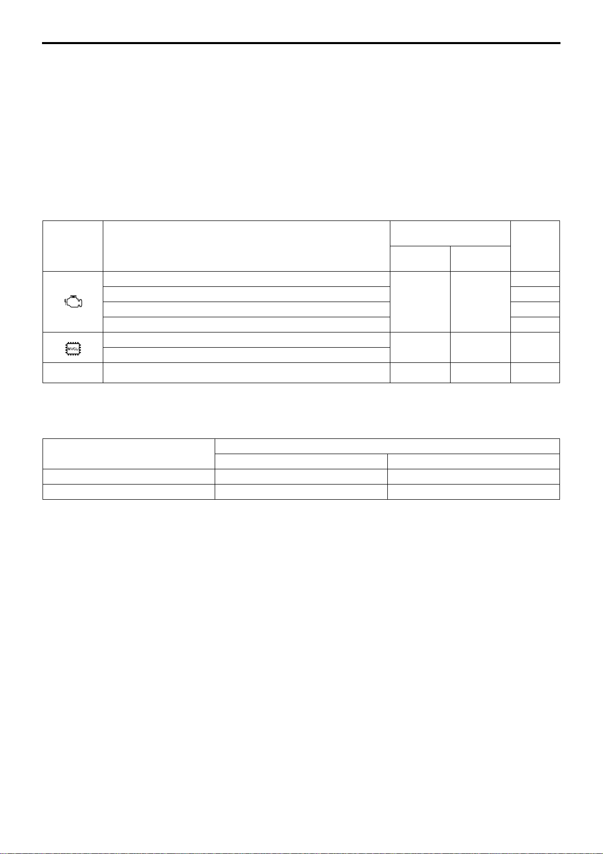
1.1 Systems and diagnosis code displaying methods
Diagnosis codes
Warning
lamp
System
Common rail
Turbocharger 15
Exhaust gas recirculation 17
Starter continuous energizing preventing function 54
Vehicle speed limiting (SLD)
Auto cruise
displaying methods
Multi-Use
Te st e r
OO
OO54
Flashing of
warning lamp
Reference
Gr
13
– Full auto air conditioner O O 55
1.2 Types of diagnosis codes
• There are two types of diagnosis code output method depending on the system: one has a distinction of present
and past codes, and the other does not have such a distinction.
System
Except below O –
Full auto air conditioner – O
With distinction of present and past Without distinction
(1) The system that has a distinction of present and past diagnosis codes
(1.1) Present diagnosis code
• Fault developed in the vehicle after the starter switch is set to ON is indicated by corresponding diagnosis code.
• The fault warning lamp is lit at the same time.
(1.2) Past diagnosis code
• Past fault developed in the vehicle is indicated by corresponding diagnosis code stored in the memory of the elec-
tronic control unit.
• With the vehicle restored to its normal condition or the starter switch turned from OFF to ON after inspection or repair against present diagnosis codes, the present diagnosis code is stored as past diagnosis codes in the memory
of the electronic control unit.
• When reading out the past diagnosis codes, the warning lamp does not illuminate as such codes do not indicate
the current fault.
Diagnosis code
(2) The system that does not have a distinction of present and past diagnosis codes
• The present and past diagnosis codes are displayed together without distinction.
00-22
2. Reading and Erasing the Diagnosis Code
2.1 Using a Multi-Use Tester
(1) Connecting a Multi-Use Tester
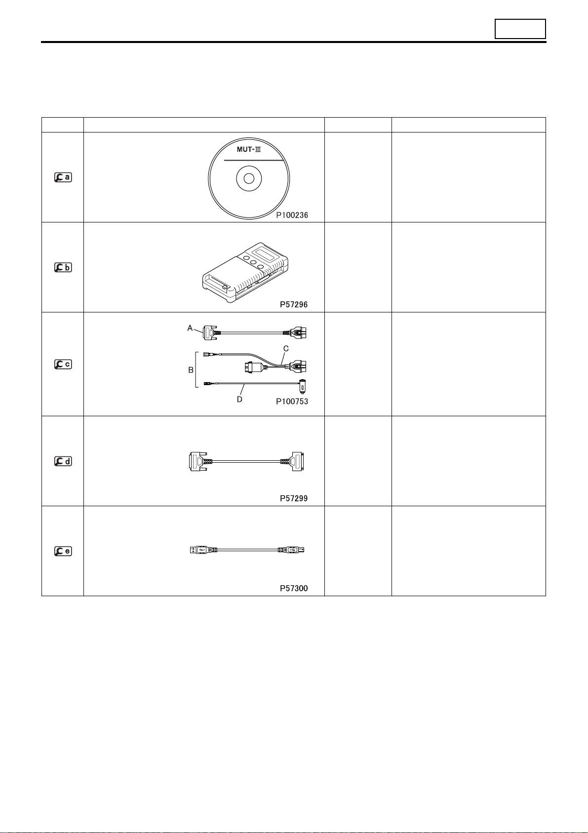
Special tools
Mark Tool name and shape Part No. Application
00
SOFTWARE DISC
Multi-Use Tester III
SOFTWARE DISC
V.C.I. MH062927
Multi-Use Tester test
Harness E
A: Harness for inspection and drive recorder
B: Harness for drive recorder
C: Drive recorder harness
D: Cigarette lighter
plug harness
FMS-E07-3*
(Multi-Use
Tester-III version)
MH063659
A: MH063661
B: MH063663
C: MH063665
D: MH063666
Installation of the Muti-Use-Tester-III
or version-up of the current version
into Multi-Use Tester-III SOFTWARE
DISC (Pub. No. SG0705A)
Data transmission between electronic
control unit and PC
Power supply to V.C.I. and communication with electronic control unit
Multi-Use Tester test
harness D
(used for extension)
USB cable MH063668
MH062951
Multi-Use Tester test harness B extension
Communication between V.C.I. and
PC
00-23

DIAGNOSIS CODES
(1.1) To perform system inspection
• Move the starter switch to the LOCK position.
• Connect PC installed , , -A a
• Conn
the vehicle.
ect
-A connector to the Multi-Use Tester connector on
nd
as shown.
(1.2) To use drive recorder function
• Move the starter switch to the LOCK position.
• Connect PC installed , , -A
as shown.
• Conn
• Connect the cigarette lighter plug
(1.3) To extend the Multi-Use Tester test harness
• Connect to -A to extend the test harness to use the
ect
the vehicle.
er socket on the vehicle.
Multi-Use Tester outside the vehicle.
-C connector to the Multi-Use Tester connector on
of
, -C,
-D to the cigarette light-
-D and
00-24
00
(2) Access of diagnosis code
• Set the starter switch to ON.
• Operate the Multi-Use Tester for a display of necessary diagnosis code stored in the memory of the electronic
control unit and identify the location of the fault.
(3) Clearing of diagnosis code
• Set the starter switch to ON (the engine not to be started).
• Operate the Multi-Use Tester to delete all the diagnosis codes stored in the memory of the electronic control unit.
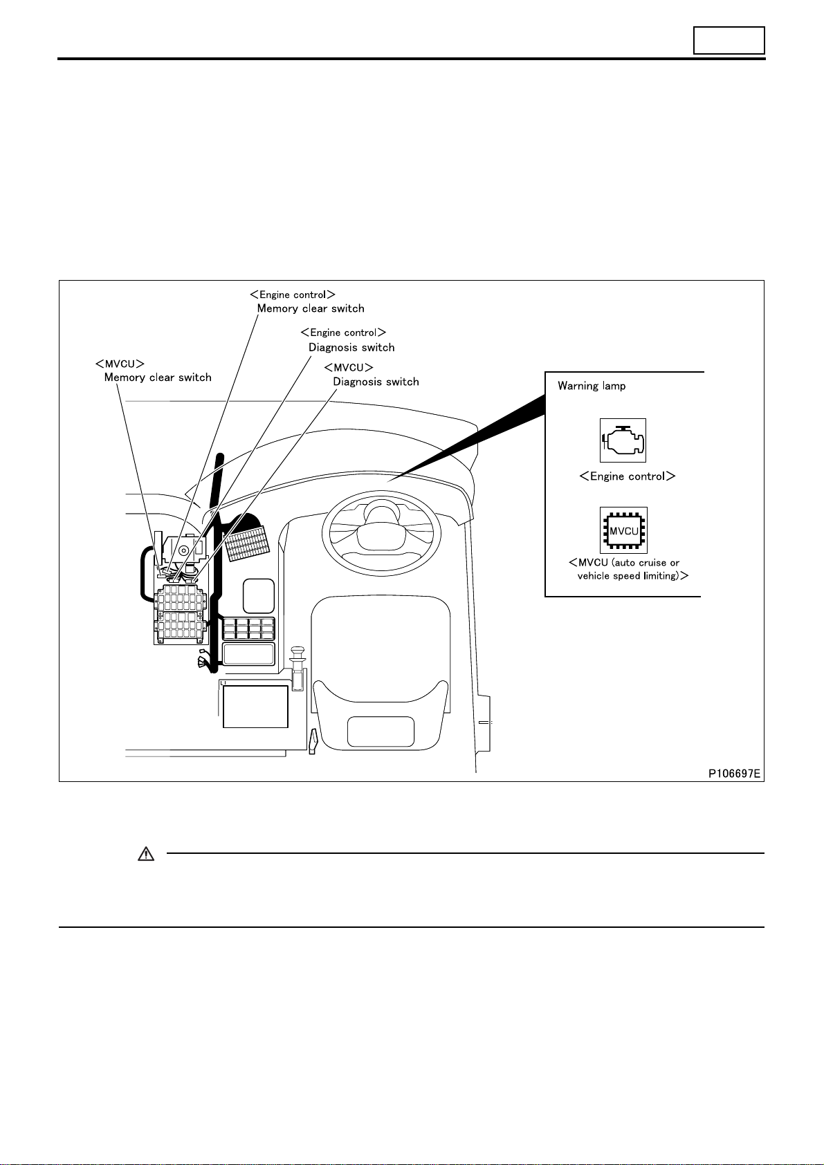
2.2 Using flashing of a warning lamp on meter cluster
(1) Engine control, vehicle speed limiting (SLD), auto cruise
• Using the diagnosis and memory clear switches, display diagnosis codes.
CAUTION
• Opening the memory clear switch followed by its reconnection will erase the stored diagnosis codes from
the memory. To avoid inadvertently erasing necessary codes, be sure to read well the procedure described below before handling diagnosis codes.
00-25
DIAGNOSIS CODES
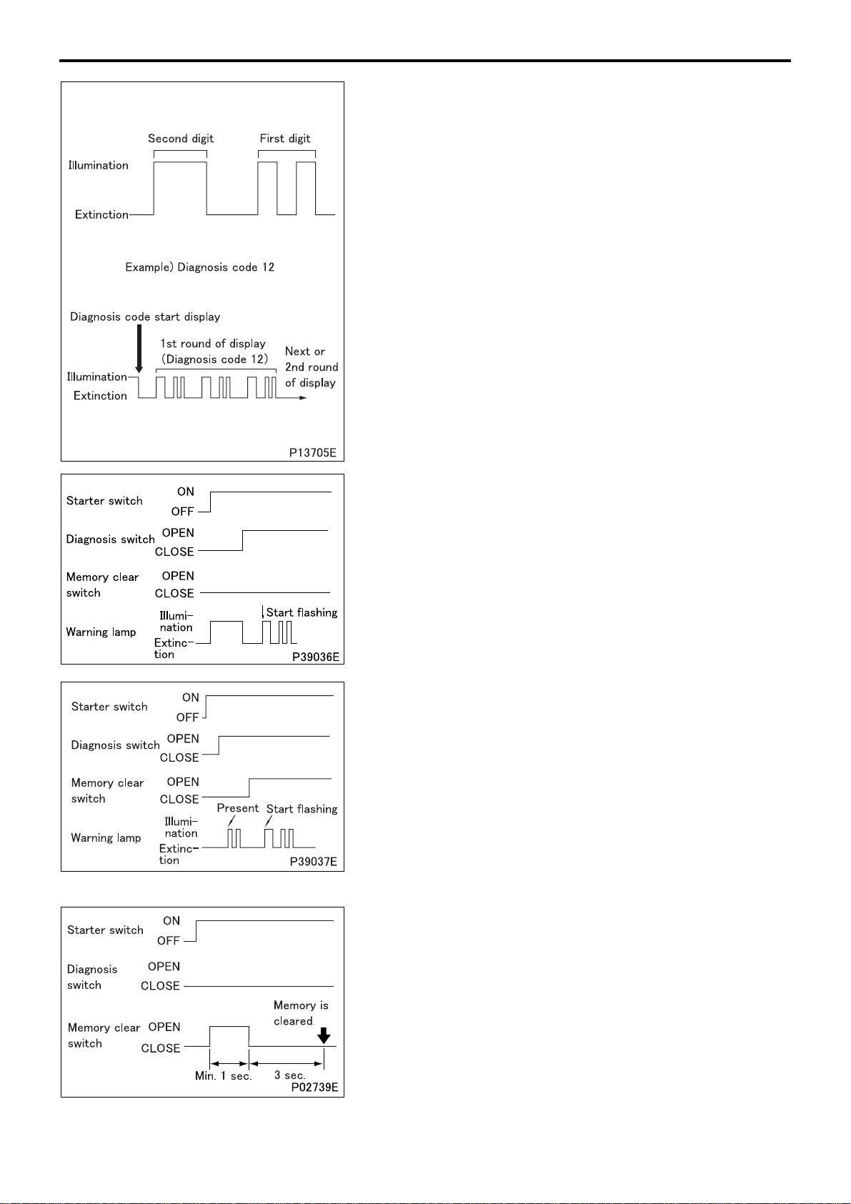
(1.1) Reading diagnosis codes
• To read a diagnosis code, observe how may times the warning
lamp flashes and how long each illumination lasts.
• The duration of illumination differs between the first and second
digits.
• Second digit: 1.2 sec.
• First digit: 0.4 sec.
• A diagnosis code consists of the flashing of second digit and the
flashing of first digit in that order. If a diagnosis code has “0” in
the second digit, only the first digit will be displayed.
• The diagnosis code 01 will be displayed if the system is normal.
• The same diagnosis code will be displayed 3 times in a row be-
fore moving to the display of the next code.
• After the last diagnosis code is displayed, the first code will be
displayed again 3 times in a row and then the subsequent
codes. This will be repeated.
(1.2) Present diagnosis codes
• Turn the starter switch ON.
• Remove the diagnosis switch.
• Present diagnosis codes will be displayed by flashing of the
warning lamp.
• When the diagnosis switch is connected, electronic control unit
will stop (terminate) displaying diagnosis codes.
(1.3) Present and past diagnosis codes
• Turn the starter switch to the ON position.
• Open the diagnosis switch.
• Present diagnosis codes will be displayed by flashing of the
warning lamp.
• Open the memory clear switch.
• Present and past diagnosis codes will be displayed by flashing
of the warning lamp.
• Turn the starter switch to the OFF position and connect the
memory clear switch and diagnosis switch to terminate the diagnosis code displaying mode.
00-26
(1.4) Erasing diagnosis codes
• Turn the starter switch to the ON position (do not start the en-
gine).
• Open the memory clear switch and reconnect it; all diagnosis
codes stored in electronic control unit memory will be erased.
To cancel diagnosis code erasure after opening the memory
clear switch, turn the starter switch to the OFF position and then
reconnect the memory clear switch.
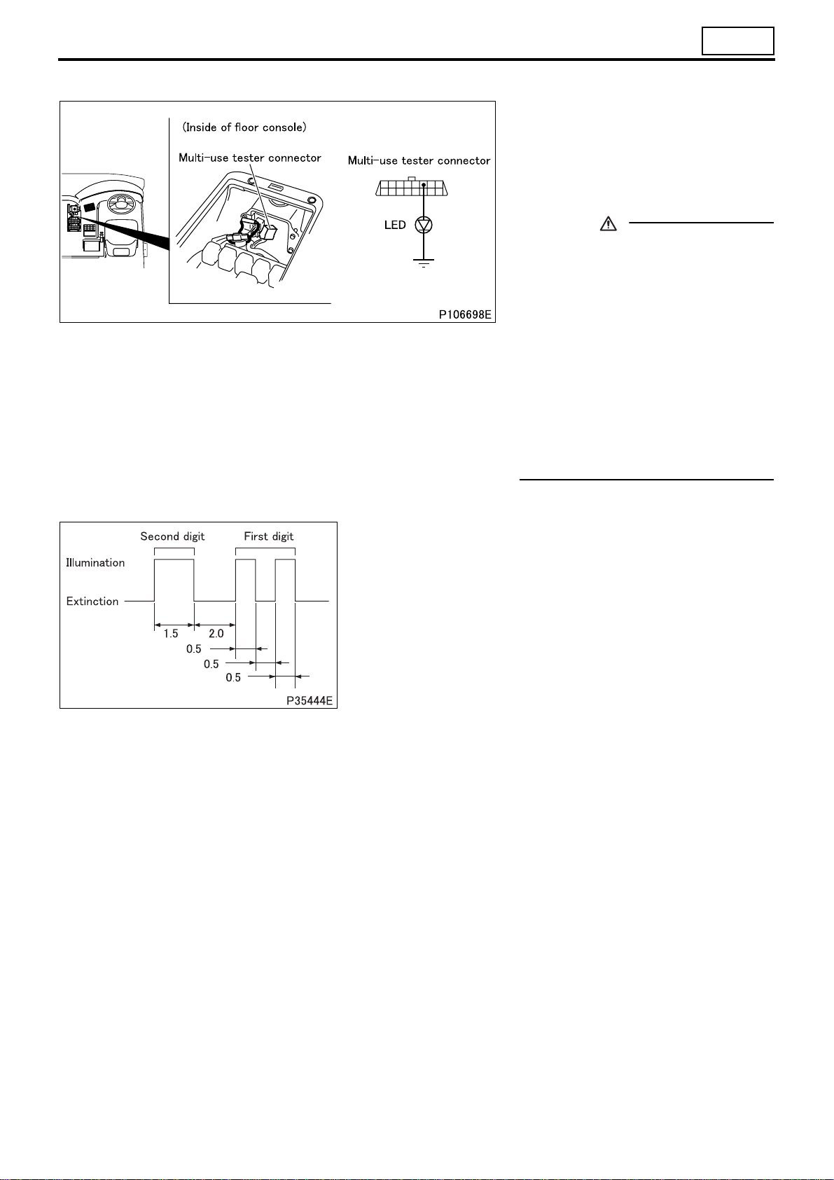
(2) Full automatic air conditioner
00
(2.1) Connection of LED for inspec-
tion
• Move the starter switch to the LOCK
position.
• Connect the LED for inspection to the
Multi-Use Tester connector.
CAUTION
• Air conditioner electronic control
unit and control panel has a backup
power supply to keep diagnostic
check results in memory. If this
power supply is cut off, with battery
cables disconnected, for example,
stored data are erased.
• Air conditioner electronic control
unit and control panel enters into
the mode of control during fault immediately a fault occurs. In this
mode, control is effected to minimize trouble arising from the fault.
(2.2) Reading and erasing diagnosis codes
• To read a diagnosis code, observe how may times the LED for
inspection flashes and how long each illumination lasts.
• The duration of illumination differs between the first and second
digits.
• Second digit: 1.5 sec.
• First digit: 0.5 sec.
• A diagnosis code consists of the flashing of second digit and the
flashing of first digit in that order. If a diagnosis code has “0” in
the second digit, only the first digit will be displayed.
• When two or more faults occur at a time, relevant diagnosis
codes are displayed repeatedly starting from the first Code.
• To erase a diagnosis code from the memory after inspection,
disconnect negative (–) battery cable and leave it disconnected
for more than 30 seconds.
00-27
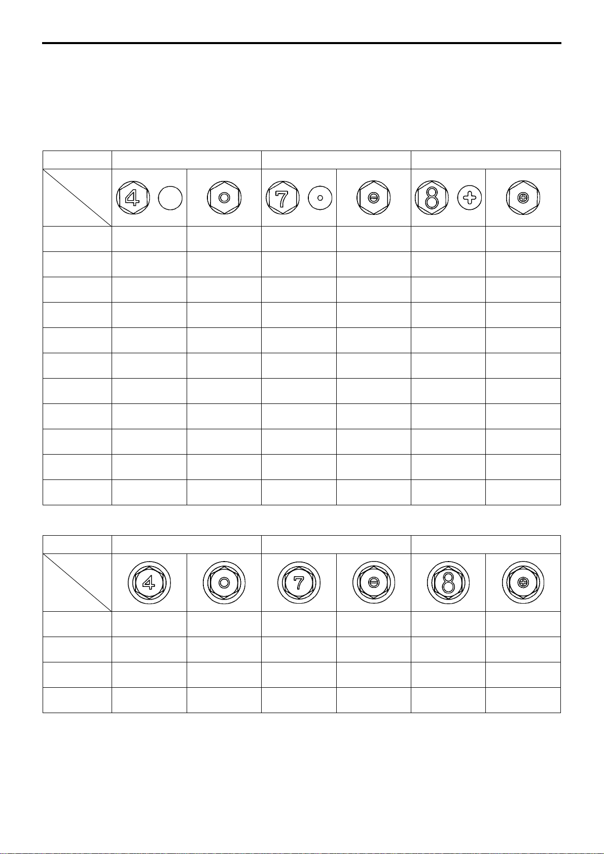
TABLE OF STANDARD TIGHTENING TORQUES
• Use specified bolts and nuts. Tighten them to the torques shown below as appropriate, unless otherwise speci-
fied.
• Threads and bearing surfaces shall be dry.
• If the mating nut and bolt (or stud bolt) are different in level of strength, tighten them to the torque specified for the
bolt.
Hexagon Head Bolts and Stud Bolts (Unit: N·m {kgf·m})
Strengt h
Identification
symbol
Nominal
diameter (stud) (stud) (stud)
M5
M6
M8
M10
M12
M14
M16
M18
M20
M22
M24
2 to 3
{0.2 to 0.3}
4 to 6
{0.4 to 0.6}
9 to 13
{0.9 to 1.3}
18 to 27
{1.8 to 2.7}
34 to 50
{3.4 to 5.1}
60 to 80
{6.0 to 8.0}
90 to 120
{9 to 12}
130 to 170
{14 to 18}
180 to 240
{19 to 25}
250 to 330
{25 to 33}
320 to 430
{33 to 44}
4T 7T 8T
–
–
–
17 to 25
{1.8 to 2.6}
31 to 45
{3.1 to 4.6}
55 to 75
{5.5 to 7.5}
90 to 110
{9 to 11}
120 to 150
{12 to 16}
170 to 220
{17 to 22}
230 to 300
{23 to 30}
290 to 380
{29 to 39}
4 to 6
{0.4 to 0.6}
7 to 10
{0.7 to 1.0}
16 to 24
{1.7 to 2.5}
34 to 50
{3.5 to 5.1}
70 to 90
{7.0 to 9.5}
110 to 150
{11 to 15}
170 to 220
{17 to 23}
250 to 330
{25 to 33}
340 to 460
{35 to 47}
460 to 620
{47 to 63}
600 to 810
{62 to 83}
–
–
–
32 to 48
{3.3 to 4.9}
65 to 85
{6.5 to 8.5}
100 to 140
{11 to 14}
160 to 210
{16 to 21}
220 to 290
{23 to 30}
310 to 410
{32 to 42}
420 to 560
{43 to 57}
540 to 720
{55 to 73}
5 to 7
{0.5 to 0.7}
8 to 12
{0.8 to 1.2}
19 to 28
{2.0 to 2.9}
45 to 60
{4.5 to 6.0}
80 to 105
{8.5 to 11}
130 to 170
{13 to 17}
200 to 260
{20 to 27}
290 to 380
{30 to 39}
400 to 530
{41 to 55}
540 to 720
{55 to 73}
700 to 940
{72 to 96}
–
–
–
37 to 55
{3.8 to 5.7}
75 to 95
{7.5 to 10}
120 to 160
{12 to 16}
190 to 240
{19 to 25}
250 to 340
{26 to 35}
360 to 480
{37 to 49}
490 to 650
{50 to 67}
620 to 830
{63 to 85}
Hexagon Head Flange Bolts (Unit: N·m {kgf·m})
Strengt h
Identification
Nominal
diameter
M6
M8
M10
M12
symbol
4 to 6
{0.4 to 0.6}
10 to 15
{1.0 to 1.5}
21 to 31
{2.1 to 3.1}
38 to 56
{3.8 to 5.5}
4T 7T 8T
–
–
20 to 29
{2.0 to 3.0}
35 to 51
{3.5 to 5.2}
8 to 12
{0.8 to 1.2}
19 to 28
{2.0 to 2.9}
45 to 55
{4.5 to 5.5}
80 to 105
{8.0 to 10.5}
–
–
37 to 54
{3.8 to 5.6}
70 to 95
{7.5 to 9.5}
10 to 14
{1.0 to 1.4}
22 to 33
{2.3 to 3.3}
50 to 65
{5.0 to 6.5}
90 to 120
{9 to 12}
–
–
50 to 60
{5.0 to 6.5}
85 to 110
{8.5 to 11}
00-28
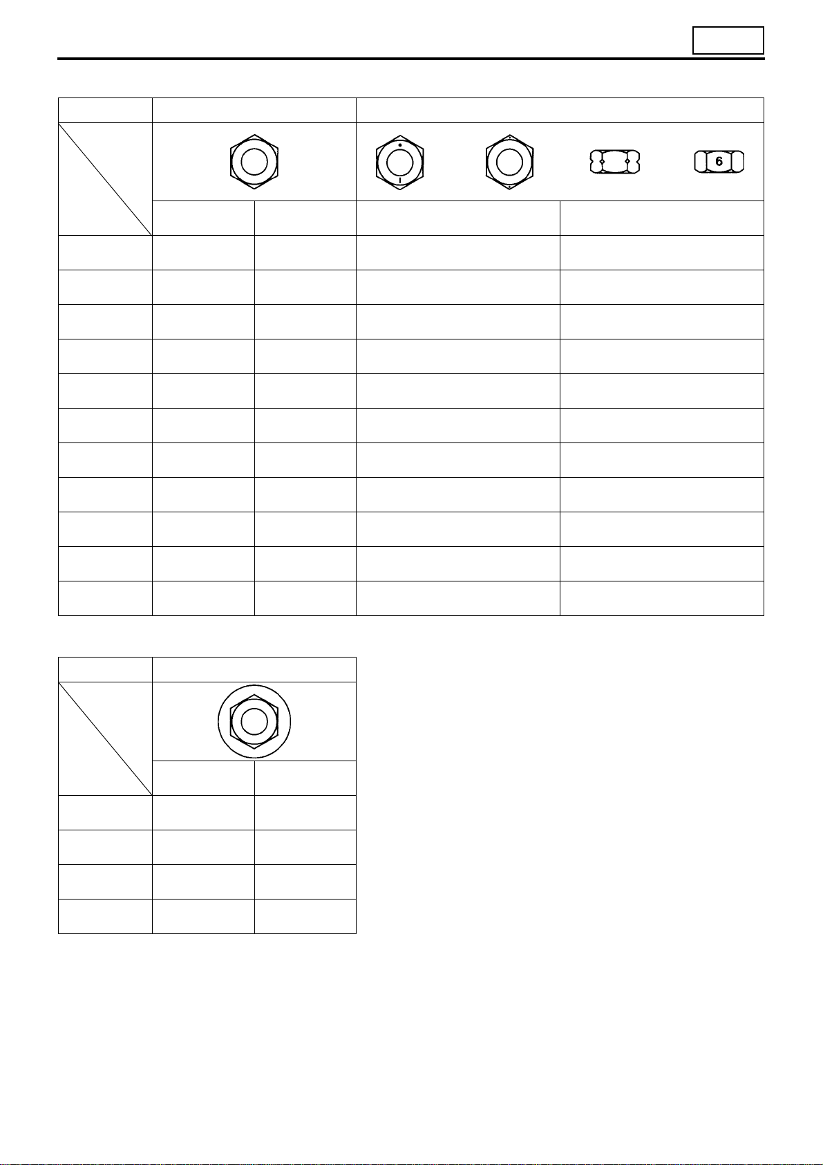
Hexagon Nuts (Unit: N·m {kgf·m})
00
Strengt h
Identification
Nominal
diameter
M5
M6
M8
M10
M12
M14
M16
M18
M20
M22
M24
symbol
Standard screw
thread
2 to 3
{0.2 to 0.3}
4 to 6
{0.4 to 0.6}
9 to 13
{0.9 to 1.3}
18 to 27
{1.8 to 2.7}
34 to 50
{3.4 to 5.1}
60 to 80
{6.0 to 8.0}
90 to 120
{9 to 12}
130 to 170
{14 to 18}
180 to 240
{19 to 25}
250 to 330
{25 to 33}
320 to 430
{33 to 44}
4T 6T
Coarse screw
thread
–
–
–
17 to 25
{1.8 to 2.6}
31 to 45
{3.1 to 4.6}
55 to 75
{5.5 to 7.5}
90 to 110
{9 to 11}
120 to 150
{12 to 16}
170 to 220
{17 to 22}
230 to 300
{23 to 30}
290 to 380
{29 to 39}
Standard screw thread Coarse screw thread
4 to 6
{0.4 to 0.6}
7 to 10
{0.7 to 1.0}
16 to 24
{1.7 to 2.5}
34 to 50
{3.5 to 5.1}
70 to 90
{7.0 to 9.5}
110 to 150
{11 to 15}
170 to 220
{17 to 23}
250 to 330
{25 to 33}
340 to 460
{35 to 47}
460 to 620
{47 to 63}
600 to 810
{62 to 83}
–
–
–
32 to 48
{3.3 to 4.9}
65 to 85
{6.5 to 8.5}
100 to 140
{11 to 14}
160 to 210
{16 to 21}
220 to 290
{23 to 30}
310 to 410
{32 to 42}
420 to 560
{43 to 57}
540 to 720
{55 to 73}
Hexagon Flange Nuts (Unit: N·m {kgf·m})
Strengt h
Identification
Nominal
diameter
M6
M8
M10
M12
symbol
Standard screw
thread
4 to 6
{0.4 to 0.6}
10 to 15
{1.0 to 1.5}
21 to 31
{2.1 to 3.1}
38 to 56
{3.8 to 5.6}
4T
Coarse screw
thread
–
–
20 to 29
{2.0 to 3.0}
35 to 51
{3.5 to 5.2}
00-29

TABLE OF STANDARD TIGHTENING TORQUES
Tightening Torque for General-Purpose Flare Nut (Unit: N·m {kgf·m})
Pipe diameter φ4.76 mm φ6.35 mm φ8 mm φ10 mm φ12 mm φ15 mm
Tightening torque 17 {1.7} 25 {2.6} 39 {4.0} 59 {6.0} 88 {9.0} 98 {10}
Tightening Torque for General-Purpose Air Piping Nylon Tube (DIN Type) (Unit: N·m
{kgf·m})
Nominal diameter
× wall thickness
Tightening torque 20 {2.0 } 34 {3.5 } 49 {5.0 } 54 {5.5 }
Tightening Torque for General-Purpose Air Piping Nylon Tube (SAE Type) (Unit: N·m
{kgf·m})
Nominal diameter 1/4 in. 3/8 in. 1/2 in. 5/8 in.
Tightening torque 13 {1.3 } 29 {3.0 } 49 {5.0 } 64 {6.5 }
6 × 1 mm 10 × 1.25 mm 12 × 1.5 mm 15 × 1.5 mm
+60+0.6
+40+0.4
0
0
+10
0
+50+0.5
+1.0
0
0
+10
0
+50+0.5
+1.0
0
0
+50+0.5
+50+0.5
0
0
00-30

GROUP 11 ENGINE
SPECIFICATIONS .............................................................................. 11-2
STRUCTURE AND OPERATION
1. Engine Proper .................................................................................... 11-3
2. Rocker and Shaft, Camshaft, Rocker Case and
inder Head Gasket .......................................................................
Cyl
3. Valve Mechanism ............................................................................... 11-4
4. Connecting Rod ................................................................................. 11-5
5. Piston .................................................................................................. 11-5
6. Timing Gears ...................................................................................... 11-6
7. Flywheel ............................................................................................. 11-6
8. Flywheel PTO ..................................................................................... 11-7
9. Powertard Brake System .................................................................. 11-8
TROUBLESHOOTING ..................................................................... 11-12
11-4
ON-VEHICLE INSPECTION AND ADJUSTMENT
1. Measuring Compression Pressure ................................................ 11-14
2. Inspection and Adjustment of Valve Clearances .......................... 11-16
3. Inspection and Adjustment of Powertard Clearances ................. 11-20
ENGINE REMOVAL AND INSTALLATION ...................................... 11-22
ROCKER COVER, ROCKER AND SHAFT ..................................... 11-26
CAMSHAFT AND ROCKER CASE ................................................. 11-30
CYLINDER HEAD AND VALVE MECHANISM ................................ 11-38
PISTON, CONNECTING ROD AND CYLINDER LINER ................. 11-54
FLYWHEEL PTO <WITH FLYWHEEL PTO> ................................... 11-68
FLYWHEEL ...................................................................................... 11-72
TIMING GEARS
<WITHOUT FLYWHEEL PTO>...................................................... 11-78
<WITH FLYWHEEL PTO> ............................................................ 11-82
CRANKSHAFT AND CRANKCASE ................................................. 11-88
11-1

SPECIFICATIONS
Item Specifications
Engine type 6M70T2 6M70T4
Type 6-cylinder, in-line, water-cooled, 4-cycle diesel engine
Combustion chamber Direct injection type
Valve mechanism Overhead camshaft (OHC) system
Maximum output kW {PS} /rpm 257 {350} / 2000 309 {420} / 2000
Maximum torque N·m {kgf·m} /rpm 1620 {165} / 1100 1810 {185} / 1100
Cylinder bore × stroke mm φ135 × 150
3
Total displacement cm
Compression ratio 17.5
Mitsubishi 6M70 Engine Parts contact:
email: EngineParts@HeavyEquipmentRestorationParts.com
Phone: 269 673 1638
{L} 12882 {12.882}
11-2
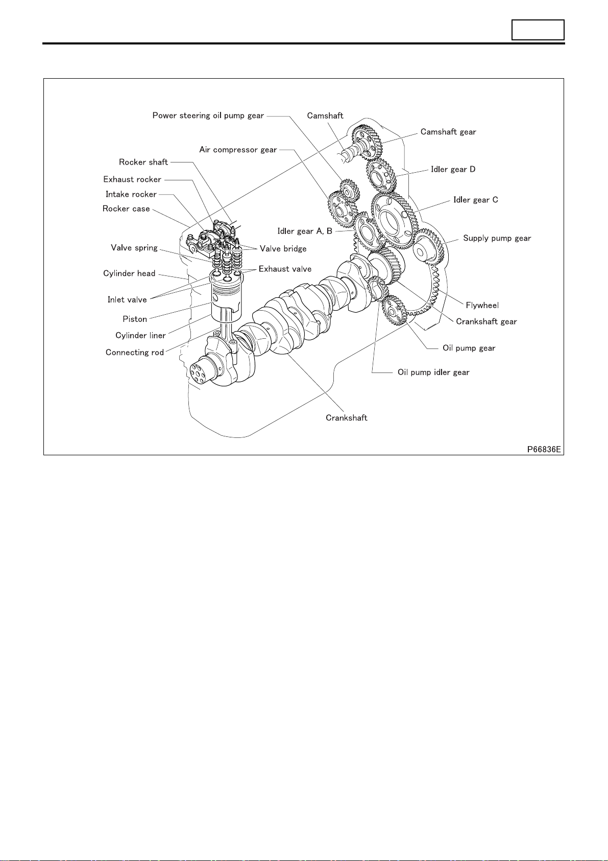
STRUCTURE AND OPERATION
1. Mitsubishi 6M70 Engine Proper
11
• The 6M70 engine employs an overhead camshaft (OHC) system, with the valve mec
gears arranged as shown above.
hanism and the timing
11-3
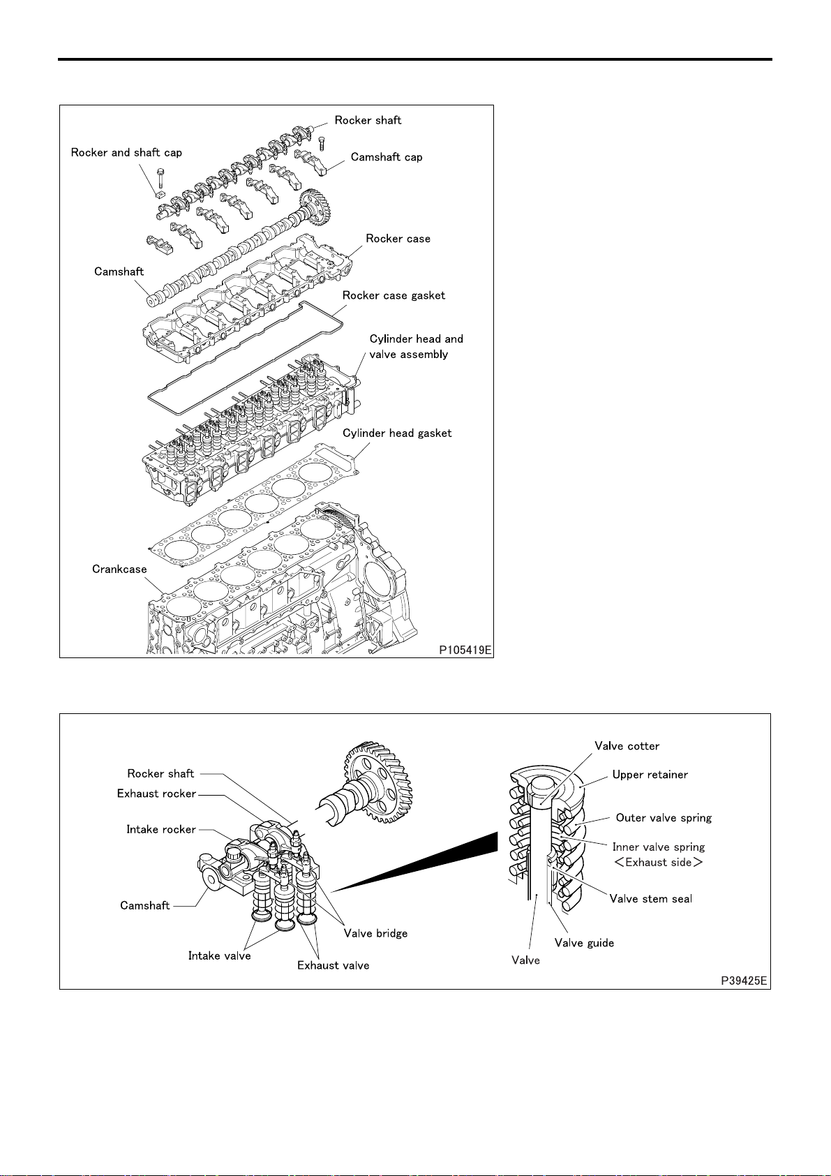
STRUCTURE AND OPERATION
2. Rocker and Shaft, Camshaft, Rocker Case and Cylinder Head Gasket
• The camshaft journals are directly
supported by the rocker case and the
camshaft cap, without using any camshaft bearings. The rocker case and
camshaft caps have been machined
together, meaning that they all need to
be replaced for a new set when one of
them becomes defective.
3. Valve Mechanism
• Each valve has a valve stem seal, which regulates the flow of lubricating oil to the contact surface between the
valve and the valve guide.
• The valve springs have a variable pitch to prevent abnormal vibration at high engine speed. The exhaust valves
use a double spring, with the inner and outer springs coiled in different directions to prevent them from jamming
each other.
11-4
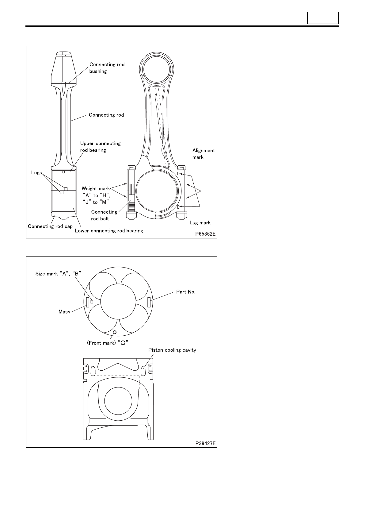
4. Mitsubishi 6M60 Connecting Rod
11
• Weight mark: “A” to “H”, “J” to “M”
• “A” indicates the greatest connecting
rod mass.
5. Mitsubishi 6M70 Piston
11-5
STRUCTURE AND OPERATION
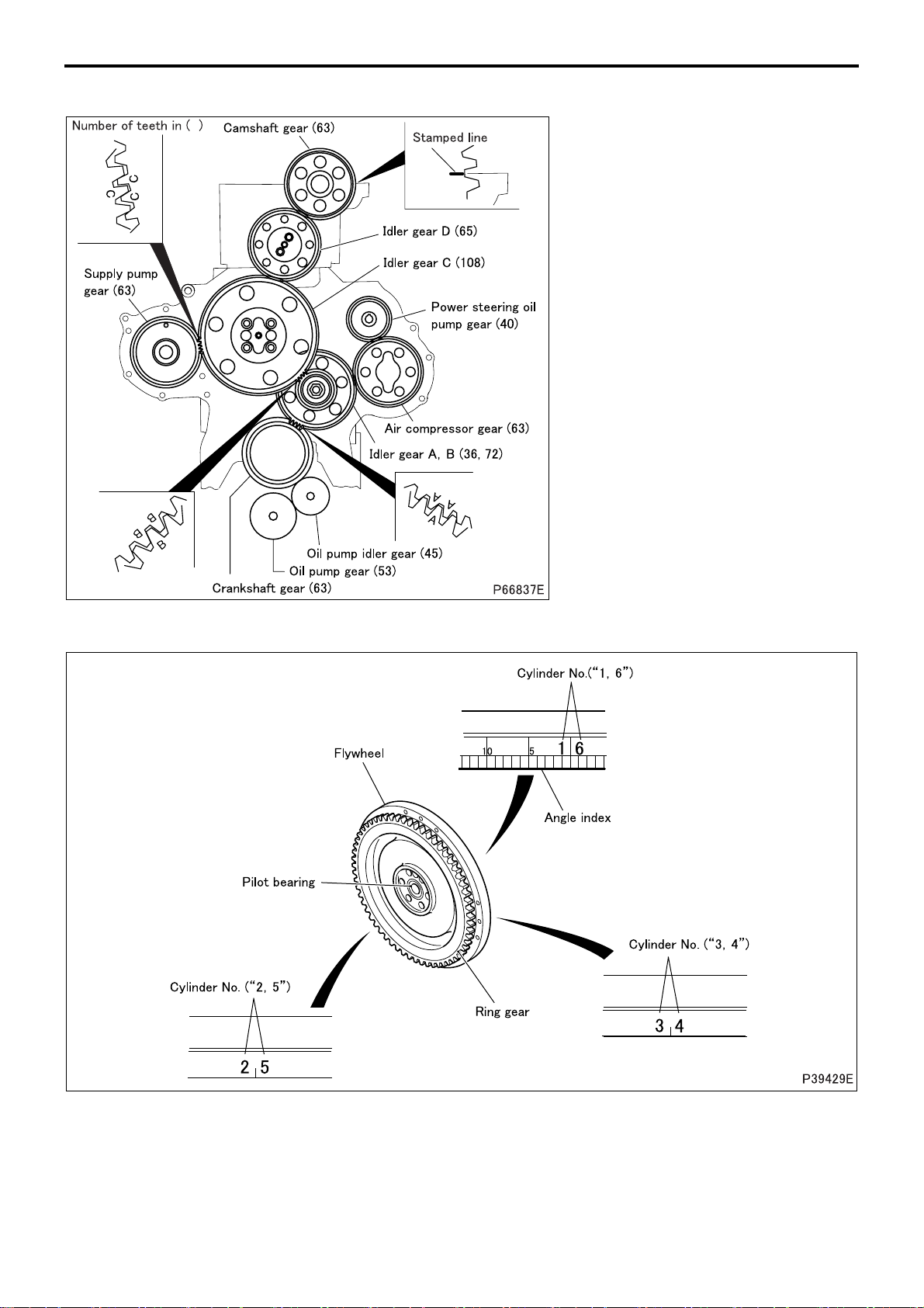
6. Mitsubishi 6M70 Timing Gears
• The timing gears are provided with
timing marks to help ensure correct
assembly.
• Timing marks are provided on the following gears.
• Camshaft gear: stamped line
• Crankshaft gear: “A”
• Idler gear A, B: “A”, “B”
• Idler gear C: “B”, “C”
• Supply pump gear: “C”
7. Flywheel
11-6
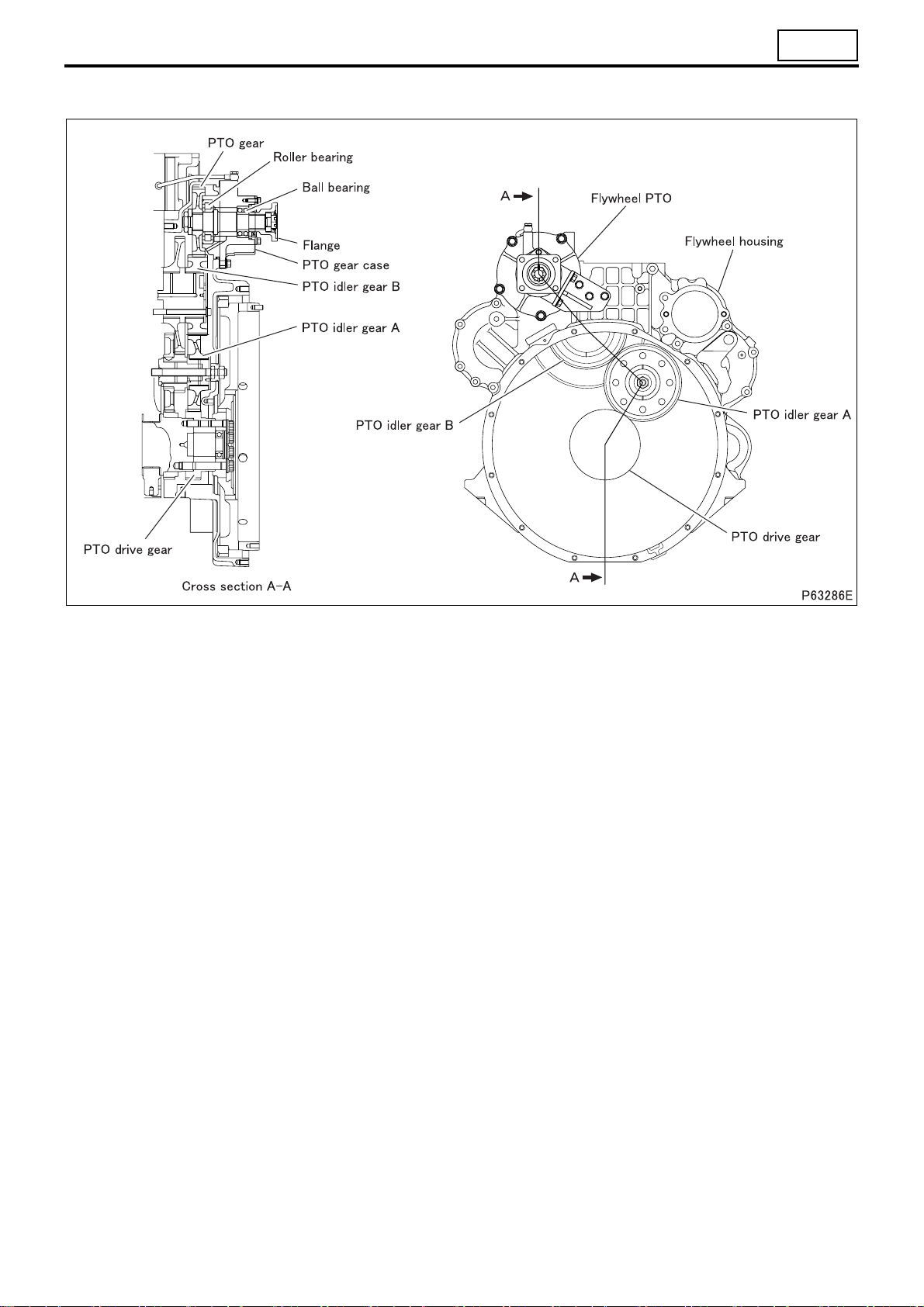
8. Flywheel PTO
11
• The flywheel PTO is located in the upper part of the flywheel housing and is driven by the PTO drive gear.
11-7
STRUCTURE AND OPERATION
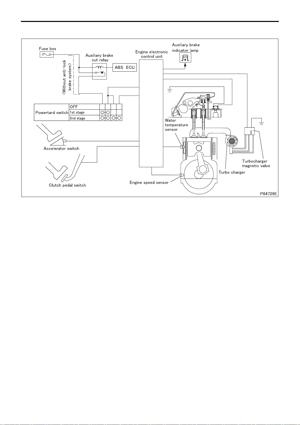
9. Powertard Brake System
• The Powertard is activated when all of the following conditions are met with the combination switch placed in the
first stage or second stage.
• Engine speed: 800 to 2400 rpm
• Clutch pedal released (clutch pedal switch: OFF)
• Accelerator pedal released (accelerator pedal switch: ON)
• Transmission in gear (transmission neutral switch: ON)
• Anti-lock brake system not activated (ABS) (Control unit: OFF) (See Gr35E.)
• If any of the above conditions are not met, operation of the Powertard system will be temporarily canceled.
If the engine speed is less than 700 rpm or higher than 2500 rpm although all the other conditions (clutch pedal,
accelerator pedal, and transmission conditions) are met, operation of the Powertard system will be canceled.
• When the vehicle speed exceeds the auto cruise set vehicle speed during driving with the auto cruise engaged,
the Powertard is activated by the control of the engine electronic control unit even if the Powertard switch (combination switch) is not turned ON. (See Gr13.)
• When the Powertard switch is placed in the first stage, the Powertard is activated to enhance the engine braking
power.
• When the Powertard switch is placed in the second stage, the turbocharger magnetic valve is activated to control
the turbocharger and generate stronger braking power than the first stage.
11-8
9.1 Operation of Powertard brake system
11
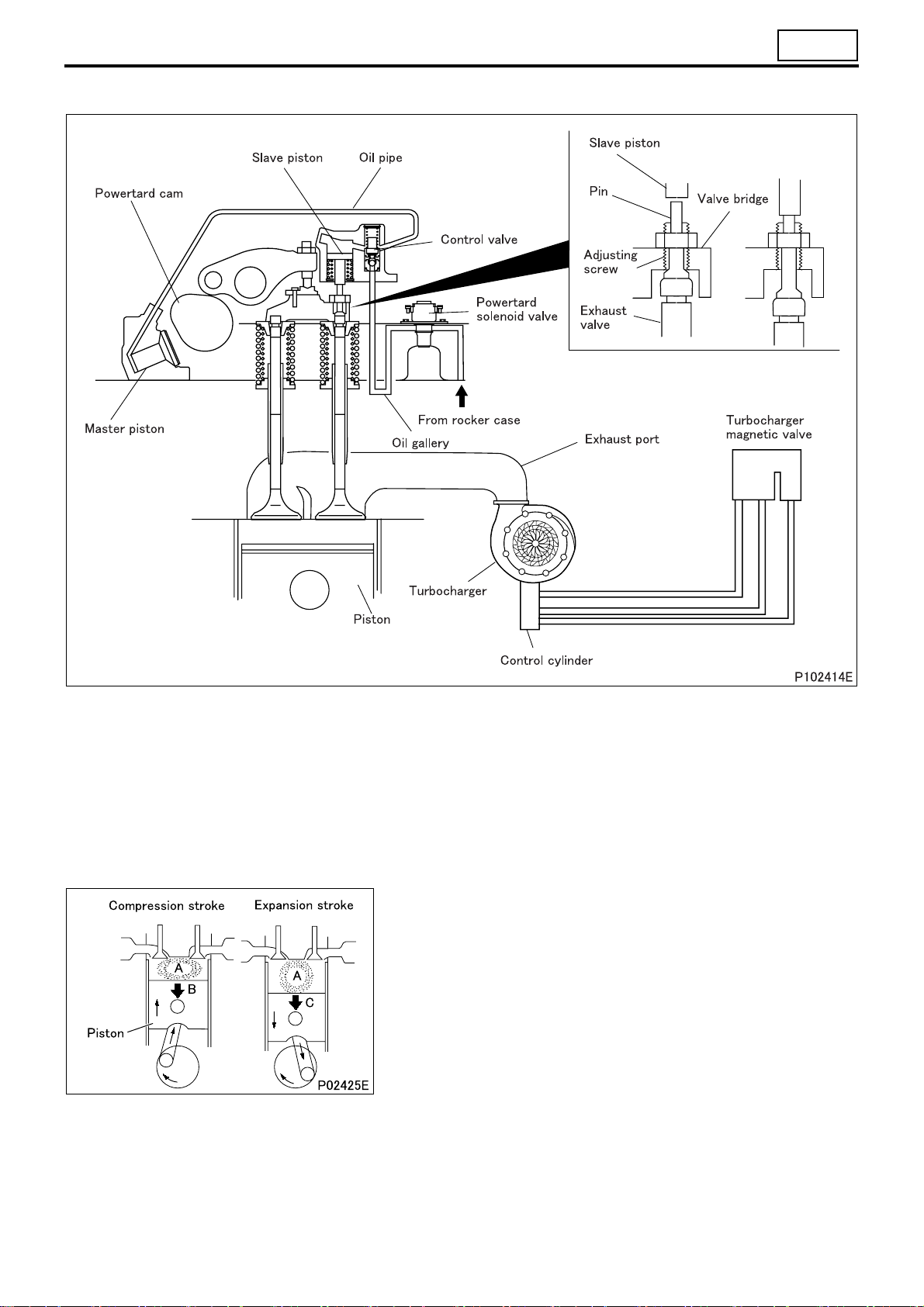
• The Powertard brake system is a device to enhance the engine brake performance. It opens and closes the ex-
haust valve (one side only) to control the volume of compressed air in the combustion chamber in accordance
with the movement of the piston, thereby providing a boosted braking force. Powertard components are located in
the cylinder head.
• The valve bridge is provided with an adjusting screw and a pin that allow the exhaust valve to be opened and
closed under the control of the Powertard, in addition to ordinary valve control.
• The pin is free to move in the adjusting screw. Its movement is controlled by the control valve.
• The adjusting screw is used to adjust the timing (Powertard clearance) for the control valve to press the pin.
(1) Operating principle
• In the ordinary engine brake, the piston is forced up during its
compression stroke when compressed air A develops a counter
force B to press the piston. This force works as a braking force.
However, the piston is forced down during its expansion stroke
to let compressed air expand. This causes an accelerating force
C to work on the piston downward, resulting in the braking force
obtained during the compression period being lost largely.
11-9
STRUCTURE AND OPERATION
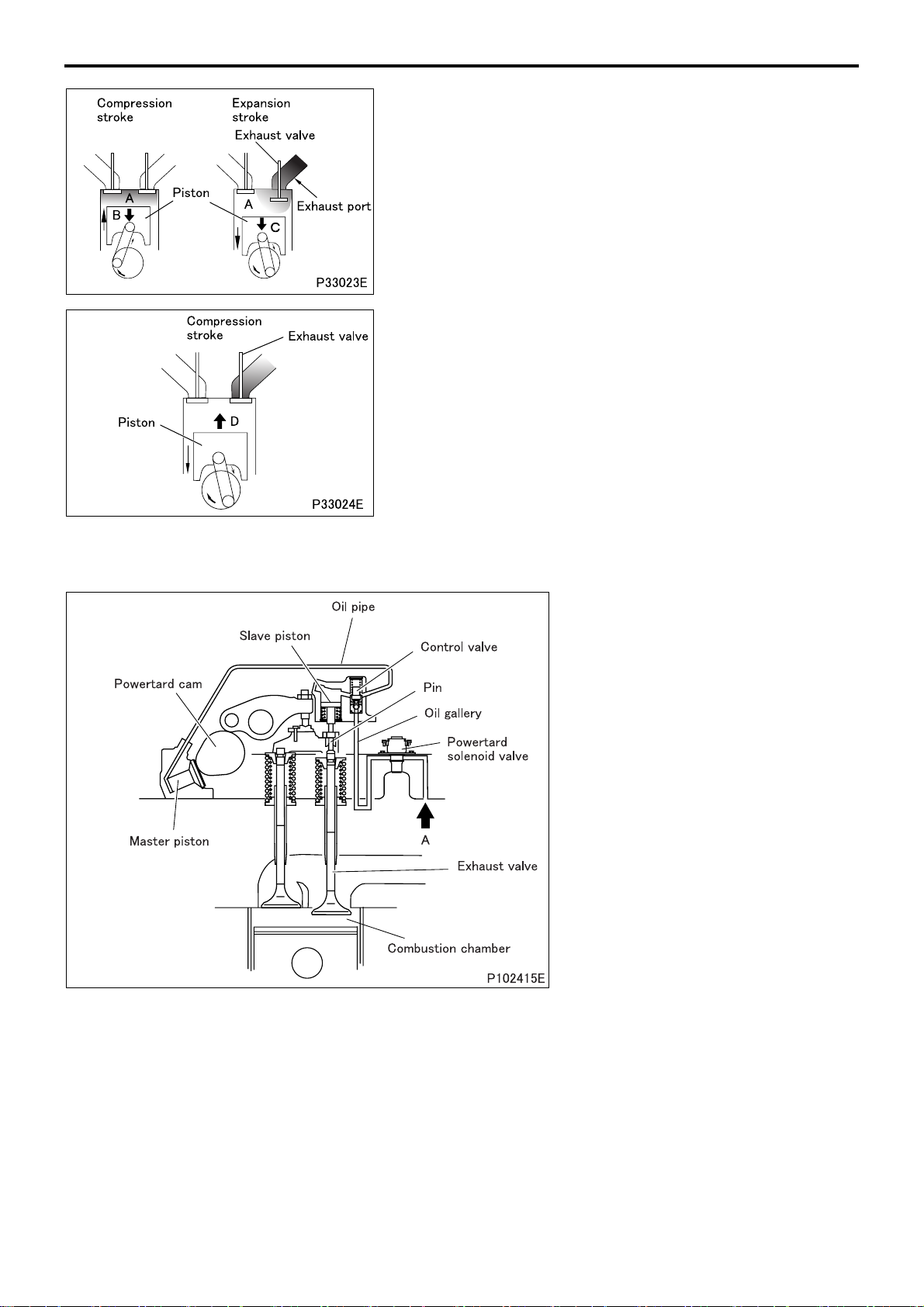
• When the Powertard system is activated, the piston pressing
force works as a braking force during the compression stroke as
when the Powertard system is not activated. During the expansion period, the exhaust valve is opened by the working of the
system to let some of the compressed air out through the exhaust po
s causes the piston pressing force to be no longer generated.
• Thi
As a result, the braking force obtained during the compression
period is maintained for effective use.
• After letting out more compressed air, the exhaust valve is
closed, which causes the combustion chamber to be closed up.
As a result, during the expansion period, a new force is generated which hinders the movement of piston when it goes down.
This force, following the braking force obtained during the previous compression period, also acts as a braking force, enhancing
greatly the vehicle’s engine brake capacity
The
operation of the system which causes the valve to be
opened and closed in agreement with the successive piston
strokes is called synchronized operation.
• As shown above, when the Powertard system is activated, the
engine brake provides more power than the ordinary engine
brake.
rt.
.
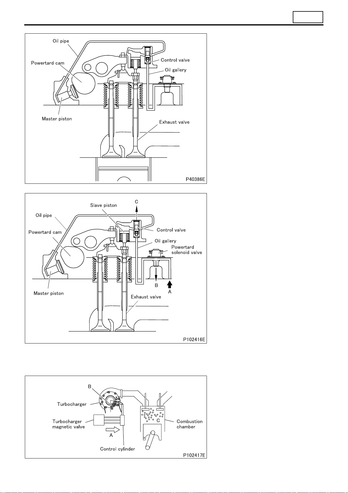
(2) Hydraulic pressure control
• When the solenoid valve is activated,
engine oil (oil pressure produced by
ordinary engine oil pump) is let in from
A to flow through the oil passage and
forces open the check valve in the
control valve.
• Oil pressure proceeds through the oil
passage to move the master piston
into contact with the dedicated Powertard cam.
• This allows the rotation of the dedicated Powertard cam to be transmitted to
the master piston. As the cam lobe top
is reached, oil pressure in the oil passage further builds up, forcing the
check valve in the control valve to
close and working on the slave piston
at the same time.
• The slave piston pushes the pin, which
in turn forces the exhaust valve to
open. As a result, the pressure in the
combustion chamber is released to
maintain effective braking force.
11-10
11
• As the Powertard cam further rotates
and the cam lobe top leaves the master piston, the oil pressure in the oil
passage is reduced.
• As a result, the exhaust valve is
closed by its spring force, which allows
the valve to open and close according
to ordinary valve timing. At the same
time, the check valve in the control
valve opens to let engine oil (oil pressure produced by ordinary engine oil
pump) work through the oil passages
and, allowing the exhaust valve to be
forced open again through the movement of the Powertard cam.
• When the Powertard release conditions are met, the following sequence
of operation is followed.
• When the solenoid valve is de-ener-
gized, the control valve shuts the incoming path (A) for engine oil from
the rocker case and opens the outgoing path (B) to the cylinder head.
• Engine oil in the oil passage is let
out through B, relieving the control
valve of oil pressure.
• The control valve opens the path
(C)
th
at has been closed by oil pressure to let out engine oil in the
chamber of the slave piston and oil
passage.
• As the oil pressure is removed, the
master piston is lowered to leave
the Powertard cam.
• At the same time, the slave piston is
forced up by the spring force. As a
result, the exhaust valve is closed
and the Powertard is turned off.
(3) Powertard brake control (Power-
tard: Switch is placed in the second stage)
• The turbocharger magnetic valve
feeds air A to the air cylinder, narrowing turbine vane B.
• The number of revolutions of the turbocharger increases, taking more air
into the combustion chamber.
• Compressed air C increases and the
braking force of the Powertard becomes stronger.
11-11

TROUBLESHOOTING
Symptoms
Reference Gr
Possible causes
Valve clearance incorrect O O
Defective cylinder head gasket O O
Cylinder head and valve
mechanism
Timing gears
Camshaft
Pistons and connecting
rods
Crankshaft
Fuel system
Cooling system
Intake and exhaust
system
Oil viscosity unsuitable O Gr12
Improper fuel O
Incorrectly fitted piping and hoses O
Defective/incorrectly fitted alternator and other auxiliaries O Gr54
Valve and valve seat worn and carbon deposits O O
Valve spring fatigued O O
Defective rocker shaft and bracket O
Poor lubrication of rocker shaft and bracket assembly O
Defective backlash between gears O
Poor lubrication of gearts and idler shaft O
Camshaft end play excessive O
Camshaft worn O
Piston ring groove(s) worn and damaged O O
Piston ring(s) worn and damaged O O
Piston pin and connecting rod small end worn O
Crankshaft end play excessive O
Fan pulley improperly mounted O
Crankshaft pins and connecting rod bearings worn or
damaged
Crankshaft journals and main bearings worn or damaged O
Defective supply pump O O
Air trapped in fuel system O
Cooling system malfunction O
Belts loose/damaged O
Air cleaner colgged O O
Turbocharger malfunction O O
Diesel particulate filter colgged O O Gr15
Low power output
Abnormal engine noise
O
Gr13Defective injector O O
Gr14
Gr15
11-12

Powertard Brake System
11
Symptoms
Reference Gr
Possible causes
Lubrication oil is cold and too viscous O O
Powertard clearance too large O
Blown fuse O
Improper connection of harnesses and connectors O
Defective clutch switch O O
Defective accelerator switch O O
Defective transmission neutral switch O O
Electrical system
Defective Powertard O O
Valve mechanism
Oil leakage in Powertard system O
Engine oil pressure too low O
Insufficient engine oil flow
Defective powertard switch (combination switch) O O
Defective meter cluster O O
Defective engine speed sensor O O
Defective powertard solenoid valve O O
Defective engine control unit O O
Defective ABS exhaust brake cut relay <ABS/ASR> O O Gr35
Broken or weak exhaust valve springs O
Exhaust valve sticky or not smooth in operation O
Improperly adjusted powertard clearance O
Air present in engine oil O
Oil leakage from around cylinder head and rocker case O
Oil passage leading to powertard assembly clogged O
Oil leakage from powertard brake system O
Defective control valve O
Powertard brake fails to operate
Turning Powertard switch OFF does not
cancel Powertard braking
Gr13
Gr12
11-13
ON-VEHICLE INSPECTION AND ADJUSTMENT
1. Measuring Compression Pressure
Service standards
Location Maintenance item Standard value Limit Remedy
2,940 kPa
{30 kgf/cm2}
–
Mitsubishi 6M70
–
Compression press
ure
Each cylinder (at 200 rpm)
Pressure difference between each cylinder
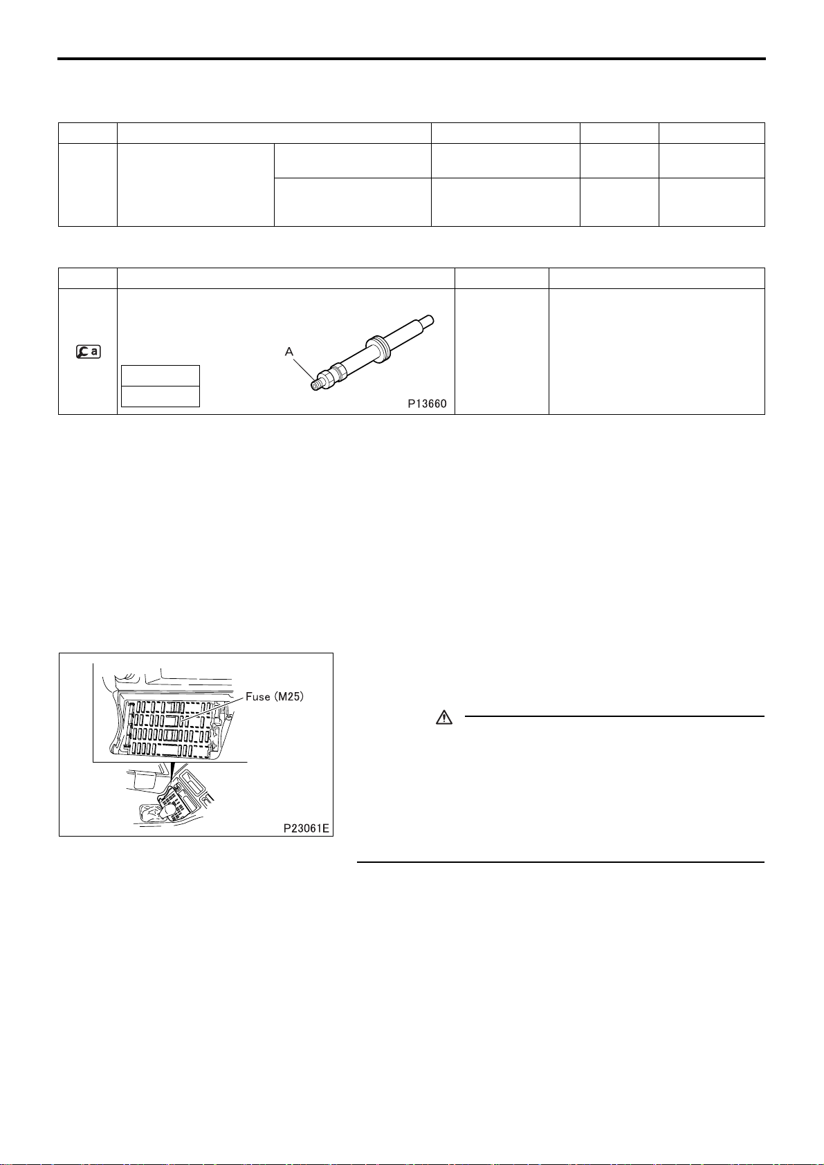
Special tools (Unit: mm)
Mark Tool name and shape Part No. Application
1,960 kPa
{20 kgf/cm2}
390 kPa
{4 kgf/cm2}
or less
Inspect
Inspect
Compression gauge
adapter
A
M14 × 1.5
MH062180 Measuring of compression pressure
• A drop in compression pressure can be used as a guide to determine when the engine should be overhauled.
• Measure the compression pressure at regular intervals. Keeping track of its transitions can provide a useful tool
for troubleshooting. On new vehicles and vehicles with newly replaced parts, the compression pressure will be
somewhat higher depending on the break-in condition of piston rings, valve seats, etc., but this will return to normal as the parts wear down.
• Before the compression measurement, confirm that the engine oil, starter, and battery are in normal condition.
• Place the vehicle in the following cond
itions.
• Warm up the engine until the coolant temperature reaches approximately 75 to 85°C.
• Turn off the lights and accessories.
• Place the transmission in N range.
• Turn the steering wheel in neutral position.
• Remove the fuse (M25) from the fuse box in the cab to prevent
fuel from being injected while the engine is cranked using the
starter.
CAUTION
• When cranking the engine, never shut off the power supplied to the engine electronic control unit by disconnecting
the engine electronic control unit connector or other similar
methods. If the engine is cranked with the power to the engine electronic control unit shut off, the supply pump will
not be controlled by the electronic control unit, causing the
supply pump to be malfunctioned.
11-14
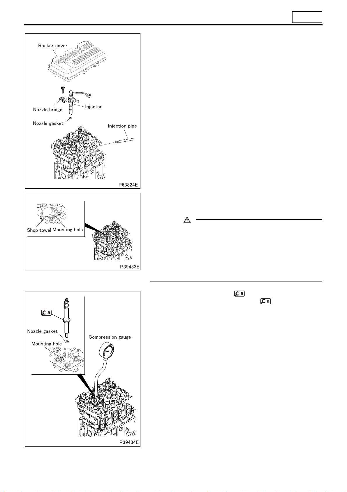
• Remove all the injectors. (See Gr13.)
11
• Cover the injector mounting holes with shop towels or other sim-
ilar cloth. Crank the engine using the starter. Ensure that no foreign matter is attached on the shop towels.
CAUTION
• If cracks or any other damage are evident in the cylinders,
this means that the coolant, engine oil or fuel, or other substances, has entered the cylinders. If this is the case, it is
extremely dangerous to crank the engine as these substances will gush out at high temperature from the injector
mounting holes. Stay away from the engine when cranking
it.
• Attach the nozzle gasket and to one of the mounting holes.
Then, connect a compression gauge to .
• Crank the engine and measure the compression pressure.
• Measure the compression pressure for all the cylinders one after
another. Determine the compression pressure difference between the cylinders.
• If the compression pressure is below the limit or the pressure difference between each cylinder is not within the limit, pour a
small amount of engine oil into the corresponding mounting hole
and measure the compression pressure again.
• If the compression pressure increases, the piston rings and
inner surfaces of cylinder may be badly worn or otherwise
damaged.
• If the compression pressure remains unchanged, there may
be seizure in the valves, the valves may be incorrectly seated
or the cylinder head gasket may be defective.
• Install the injector. (See Gr13.)
• Install the rocker cover and the gasket. (See “ROCKER COV-
ER, ROCKER AND SHAFT”.)
11-15
ON-VEHICLE INSPECTION AND ADJUSTMENT
2. Mitsubishi 6M70 Inspection and Adjustment of
:
Valve Clearances Service standards (Unit
Location Maintenance item Standard value Limit Remedy
Mitsubishi 6M70
–
Valve clearance (
when engine is cold)
Tightening torque (Unit: N·m {kgf·m})
Mark Parts to be tightened Tightening torque Remarks
–
–
k nut ( 6M70 valve bridge adjusting screw tightening) 68 {7} –
Loc
Lock nut ( 6M
70 rocker arm adjusting screw tightening) 60 {6} –
Intake side 0.4 – Adjust
Exhaust side 0.6 – Adjust
mm)
• Mitsubishi 6M70 Valve c
learances should be checked and
adjusted as follows while the engine is still cold.
[Inspection]
• Remove the rocker cover.
5
1
10
6
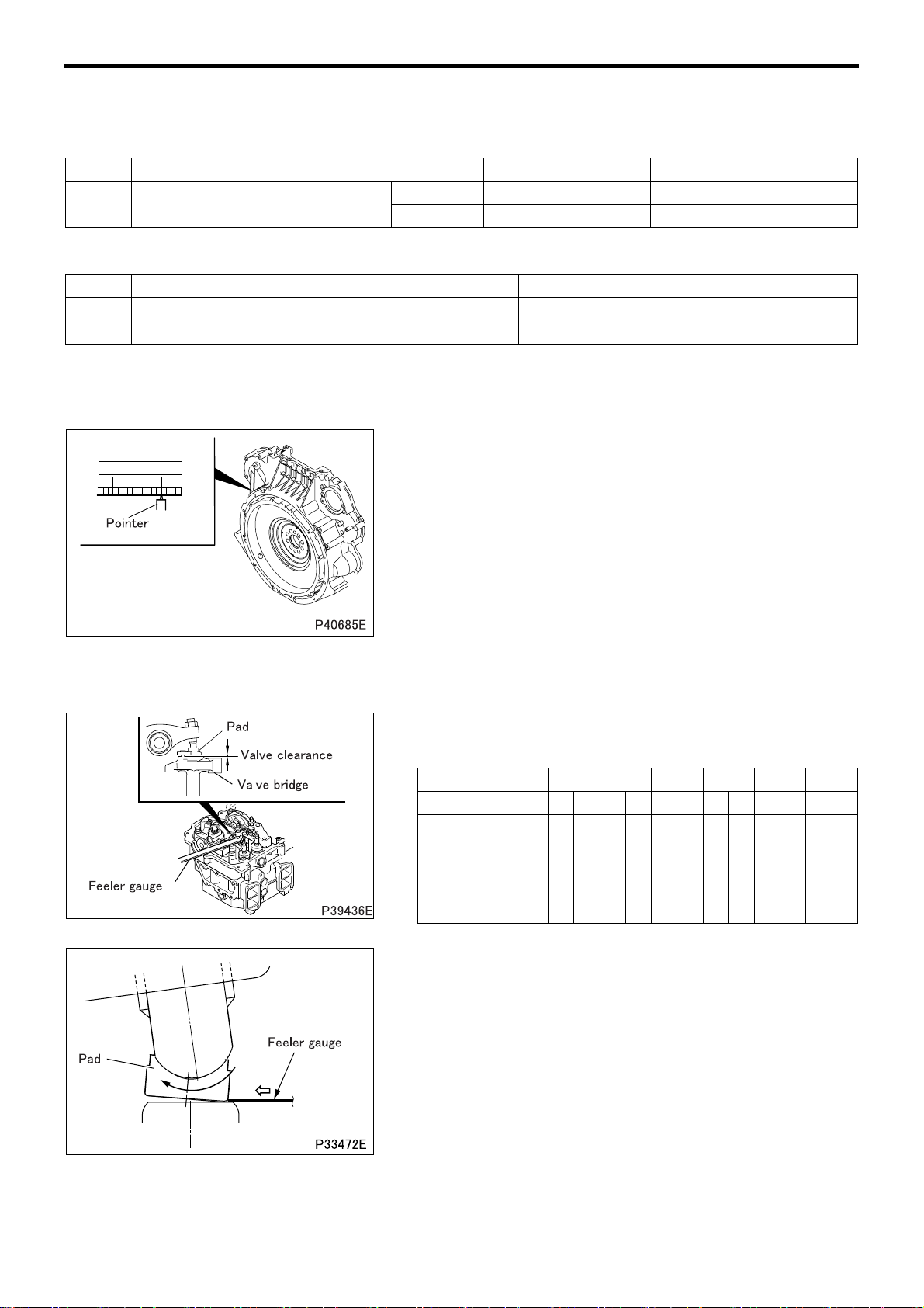
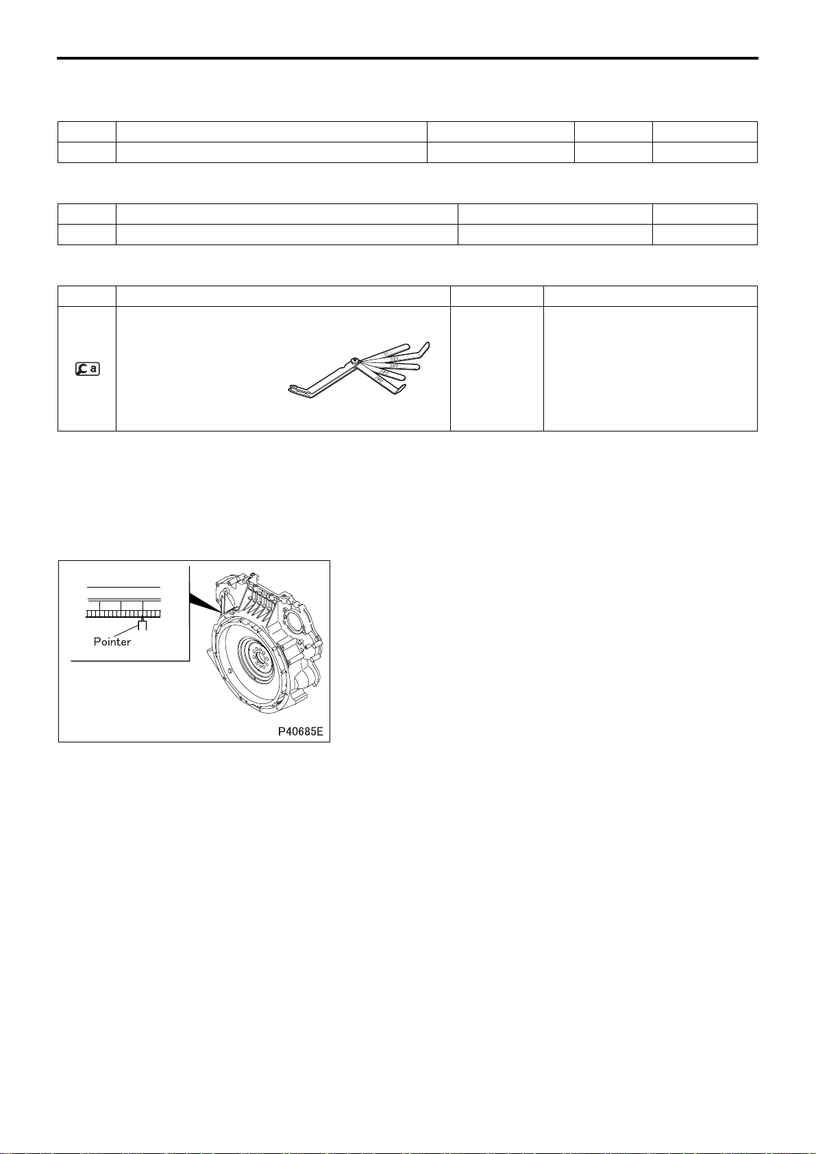
• Bring the No. 1 or No. 6 cylinder piston to the top dead center
(TDC) on the compression stroke according to the following procedure:
• Crank the engine until the pointer is aligned with the “1 6”
mark on the flywheel.
• This will place either the No. 1 or No. 6 cylinder piston at TDC
on the compression stroke. The cylinder in which the rocker
arms for both the intake and exhaust valves can be pushed
down by hand by the valve clearance amounts has its piston
at TDC. Rotate the engine by one full turn to switch the TDCs
of the No. 1 and No. 6 cylinder piston
• With
the No. 1 or No. 6 cylinder piston at TDC, measure the
s.
clearance of the valves (clearance between valve bridge and
pad) marked with a circle in the table below.
Cylinder No. 123456
Valve INEXINEXINEXINEXINEXINEX
No. 1 cylinder
piston at TDC on
compression stroke
No. 6 cylinder
piston at TDC on
compression stroke
OOO– –OO––O– –
–––OO––OO–OO
11-16
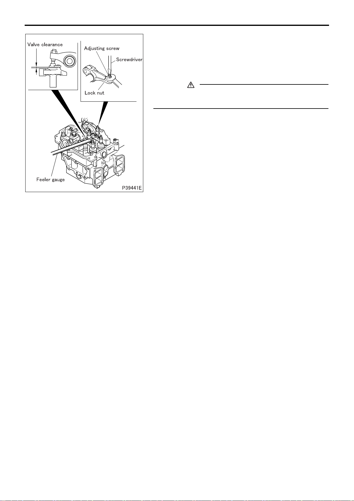
• Any attempt to insert a feeler gauge without first securing sufficient space, as described above, between the pad and the valve
bridge will fail, as the pad will tilt as shown in the illustration, thus
blocking the entry of a feeler gauge.
11
• Before inserting a feeler gauge, push the adjusting screw pad on
the side opposite from where a feeler gauge is to be inserted, as
shown in the illustration, using a flat-blade screwdriver or other
similar tool. This will create space necessary for the gauge to be
inserted.
• The measurement is correct when the feeler gauge feels slightly
resisted as it is inserted.
• The measurement is not yet correct if the feeler gauge can still
be inserted smoothly.
• If the measurement deviates from the standard value, adjust as
follows.
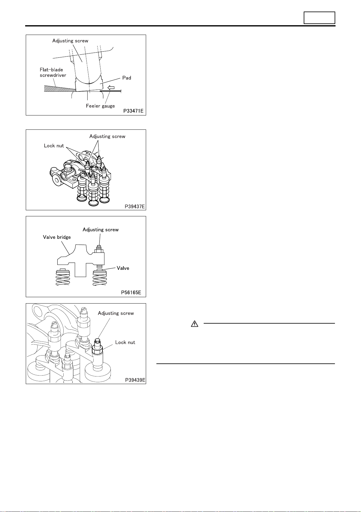
[Adjustment]
• Loosen the lock nuts and adjusting screws on the valve bridge
and rocker arm.
• While holding the valve bridge by hand, screw in the adjusting
screw until it lightly contacts the valve stem end.
• Then, further screw in the adjusting screw by 45°.
• While holding the adjusting screw in this position, tighten the
lock nuts to the specified torque.
CAUTION
• After adjusting the adjusting screw, be sure to tighten the
lock nut to the specified torque. Insufficient torquing will
compromise the parallelism of the valve bridge, damaging
the valve mechanism.
11-17
ON-VEHICLE INSPECTION AND ADJUSTMENT
• Screw in or out the adjusting screw on the rocker arm until the
correct feeler gauge can be inserted with a slight resistance.
• After adjustment, while holding the adjusting screw in this position with a screwdriver, tighten the lock nuts to the specified
torque.
• Recheck the valve clearance using the correct feeler gauge.
CAUTION
• If the valve clearance has been adjusted, be sure to check
and adjust the Powertard clearance. (See later section.)
• After the adjustment is complete, install the rocker cover and the
gasket. (See “ROCKER COVER, ROCKER AND SHAFT”.)
itsubishi 6M70 Engine Parts contact:
M
email: EngineParts@HeavyEquipmentRestorationParts.com
Phone: 269 673 1638
11-18

M E M O
11
11-19
ON-VEHICLE INSPECTION AND ADJUSTMENT
3. Inspection and Adjustment of Powertard Clearances
Service standards (Unit: mm)
Location Maintenance item Standard value Limit Remedy
– Powertard clearance (when engine is cold) 1.0 ± 0.05 – Adjust
Tightening torque (Unit: N·m {kgf·m})
Mark Parts to be tightened Tightening torque Remarks
– Lock nut (for locking Powertard assembly adjusting screw) 25 {2.6} –
Special tools (Unit: mm)
Mark Tool name and shape Part No. Application
Feeler gauge MH063474 Adjustment of Powertard Clearances
P11605
Inspection and adjustment of the Powertard clearance must be carried out after the inspection and adjustment of the valve clearance
while the engine is cold.
Inspection and adjustment of valve clearances (See 2. “Inspection
and Adjustment of Valve Clearances”.)
[Inspection]
• Remove the rocker cover.
5
1
10
6
• Bring the No. 1 or No. 6 cylinder piston to the top dead center
(TDC) on the compression stroke according to the following procedure:
• Crank the engine until the pointer is aligned with the “1 6”
mark on the flywheel.
• This will place either the No. 1 or No. 6 cylinder piston at TDC
on the compression stroke. The cylinder in which the rocker
arms for both the intake and exhaust valves can be pushed
down by hand by the valve clearance amounts has its piston
at TDC. Rotate the engine by one full turn to switch the TDCs
of the No. 1 and No. 6 cylinder pistons.
11-20
 Loading...