

Page 1

ENGINE
6G7 SERIES
CONTENTS
11A-0-1
GENERAL INFORMATION 11A-0-3
1. SPECIFICATIONS 11A-1-1
SERVICE SPECIFICATIONS 11A-1-1
REWORK DIMENSIONS 11A-1-2
TORQUE SPECIFICATIONS 11A-1-3
SEALANTS 11A-1-5
FORM-IN-PLACE GASKET 11A-1-6
2. SPECIAL TOOLS 11A-2-1
3. ALTERNATOR 11A-3-1
4. AIR INTAKE PLENUM 11A-4-1
5. IGNITION SYSTEM 11A-5-1
6. TIMING BELT 11A-6-1
7. INTAKE MANIFOLD 11A-7-1
8. EXHAUST MANIFOLD & WATER PUMP 11A-8-1
9. ROCKER ARMS AND CAMSHAFT 11A-9-1
.....................................................
...................................................
....................................................
...........................................
...............................................
..................................
.......................................
...................................
....................................
................................................
...........................................
..............................................
.............................................
.......................
.............................
10. CYLINDER HEAD AND VALVES 11A-10-1
11. OIL PAN AND OIL PUMP 11A-11-1
12. PISTON AND CONNECTING ROD 11A-12-1
13. CRANKSHAFT, FLYWHEEL AND DRIVE PLATE 11A-13-1
E
Dec. 1996Mitsubishi Motors Corporation
........................................
................................
..............................
..............
PWEE9615
Page 2

11A-0-2
NOTES
E
Dec. 1996Mitsubishi Motors Corporation
PWEE9615
Page 3
6G7 ENGINE (E-W) -
General Information
GENERAL INFORMATION
GENERAL SPECIFICATIONS
Descriptions 6G72-SOHC
Type 60_ OHV, SOHC
Number of cylinders 6
Combustion chamber Compact type
11A-0-3
Total displacement dm
Cylinder bore mm 91.1
Piston stroke mm 76.0
Compression ratio 8.9
V alve timing Intake valve Opens (BTDC) 15°
(Camshaft identification mark: 1)
Lubrication system Pressure feed, full-flow filtration
Oil pump type Trochoid type
Cooling system Water-cooled forced circulation
Water pump type Centrifugal impeller type
3
Closes (ABDC) 53°
Exhaust valve Opens (BBDC) 53°
Closes (ATDC) 15°
2.972
E
Dec. 1996Mitsubishi Motors Corporation
PWEE9615
Page 4
6G7 ENGINE (E-W) -
Specifications
1. SPECIFICATIONS
SERVICE SPECIFICATIONS
Items Standard Limit
Timing belt
Auto-tensioner rod length mm 3.8 - 5.0 -
Auto-tensioner rod projection length mm 12 -
11A-1-1
Auto-tensioner rod pushed-in amount (when pushed with a force of 98
- 196 N) mm
Rocker arms and camshaft
Camshaft cam height mm (Identification
mark: 1)
Camshaft journal outside diameter mm 45 -
Lash adjuster leak down time
[diesel fuel at 15 - 20_C] seconds/mm
Cylinder head and valves
Cylinder head flatness of gasket surface mm Less than 0.03 0.2
Cylinder head grinding limit of gasket surface mm
(Total resurfacing depth of both cylinder head and cylinder block)
Cylinder head overall height mm 120 -
V alve thickness of valve head (margin) mm
Valve overall height mm
Intake 37.71 37.21
Exhaust 37.14 36.64
Intake 1.0 0.5
Exhaust 1.2 0.7
Intake 112.30 111.80
Exhaust 114.11 113.61
1.0 or less -
4 - 20/1.0 -
- 0.2
V alve stem outside diameter mm
V alve thickness to valve guide clearance mm
V alve face angle mm 45_ - 45.5_ -
V alve spring free length mm 51.0 50.0
V alve spring load/installed height N/mm 267/44.2 -
V alve spring out-of-squareness 2_ or less Maximum 4_
Valve seat valve contact width mm 0.9 - 1.3 -
Valve guide inside diameter mm 6.0 -
V alve guide projection from cylinder head upper surface mm 14 -
V alve stem projection mm 49.3 49.8
Oil pan and oil pump
Oil pump tip clearance mm 0.06 - 0.18 -
E
Dec. 1996Mitsubishi Motors Corporation
Intake 6.0 -
Exhaust 6.0 -
Intake 0.02 - 0.04 0.10
Exhaust 0.04 - 0.06 0.15
PWEE9615
Page 5
11A-1-2
Items LimitStandard
Oil pump side clearance mm 0.04 - 0.10 -
Oil pump body clearance mm 0.10 - 0.18 0.35
Piston and connecting rod
Piston outside diameter mm 91.1 -
6G7 ENGINE (E-W) -
Specifications
Piston ring to ring groove clearance mm
Piston ring end gap mm
Piston pin outside diameter mm 22.0 -
Piston pin press-in load N (Room temperature) 7,350 - 17,200 -
Crankshaft pin oil clearance mm 0.02 - 0.05 0.1
Connecting rod big end side clearance mm 0.10 - 0.25 0.4
Crankshaft, flywheel and drive plate
Crankshaft end play mm 0.05 - 0.25 0.3
Crankshaft journal outside diameter mm 60 -
Crankshaft pin outside diameter mm 50 -
Crankshaft journal oil clearance mm 0.02 - 0.05 0.1
Piston to cylinder clearance mm 0.02 - 0.04 -
No. 1 0.03 - 0.07 0.1
No. 2 0.02 - 0.06 0.1
No. 1 0.30 - 0.45 0.8
No. 2 0.45 - 0.60 0.8
Oil ring side rail 0.20 - 0.60 1.0
Cylinder block flatness of gasket surface mm 0.05 0.1
Cylinder block grinding limit of gasket surface mm
(Total resurfacing depth of both cylinder head and cylinder block)
Cylinder block overall height mm 210.5 -
Cylinder bore inside diameter mm 91.1 -
Cylindricity mm 0.01 -
- 0.2
REWORK DIMENSIONS
Items Standard value Limit
Oversize rework dimensions of valve
guide hole mm
Oversize rework dimensions of intake
valve seat hole mm
Oversize rework dimensions of
exhaust valve seat hole mm
0.05 Oversize diameter 11.05 - 11.07 -
0.25 Oversize diameter 11.25 - 11.27 -
0.50 Oversize diameter 11.50 - 11.52 -
0.3 Oversize diameter 34.30 - 34.33 -
0.6 Oversize diameter 34.60 - 34.63 -
0.3 Oversize diameter 31.80 - 31.83 -
0.6 Oversize diameter 32.10 - 32.13 -
E
Dec. 1996Mitsubishi Motors Corporation
PWEE9615
Page 6
6G7 ENGINE (E-W) -
Specifications
TORQUE SPECIFICATIONS
Items Nm
Alternator
Drive belt tensioner pulley nut 49
Crankshaft bolt 181
Alternator pivot nut 44
Alternator bolt M8 21
Alternator bolt M10 48
Dipstick tube 13
Air intake plenum
Air intake plenum stay bolt M8 17
Air intake plenum stay bolt M10 35
Accelerator cable bracket 4
11A-1-3
Bracket 11
Throttle body bolt 11
Air intake plenum bolt and nut 17
Exhaust gas recirculation valve bolt 21
Exhaust gas recirculation pipe bolt 17
Exhaust gas recirculation pipe flare nut 56
Ignition system
Spark plugs 25
Distributor 23
Timing belt
Timing belt cover bolt M6 11
Timing belt cover bolt M8 13
Engine support bracket 44
Crankshaft angle sensor bolt 9
Auto tensioner bolt 23
Tensioner pulley bolt 48
Tensioner arm bolt 44
Idler pulley bolt 44
Camshaft sprocket bolt 88
Bracket 23
Timing belt rear cover bolt 13
E
Dec. 1996Mitsubishi Motors Corporation
PWEE9615
Page 7
11A-1-4
Items Nm
Intake manifold
Engine coolant temperature gauge unit 11
Engine coolant temperature sensor 29
Heater pipe bolt 18
Water outlet fitting bolt 18
Water inlet fitting bolt 18
Thermostat housing bolt 18
Water pipe bolt 13
Delivery pipe 11
Intake manifold bolt 21
Fuel pipe bolt 8.8
Fuel pressure regulator bolt 8.8
6G7 ENGINE (E-W) -
Specifications
Exhaust manifold
Heat protector bolt 13
Exhaust manifold bolt 49
Engine hanger 35
Oil level gauge guide bolt 13
Water pump bolt M8 23
Water pump bolt M10 41
Rocker arms and camshaft
Rocker cover bolt 3.4
Rocker shaft bolt 31
Thrust case bolt 12
Cylinder head and valve
Cylinder head bolt 108
Oil pan and oil pump
Oil pressure switch 9.8
Oil filter bracket bolt M8 23
Oil filter bracket bolt M10 41
Drain plug 39
Oil pan, lower bolt 11
Cover bolt 11
E
Dec. 1996Mitsubishi Motors Corporation
PWEE9615
Page 8

6G7 ENGINE (E-W) -
Items Nm
Oil pan, upper bolt 5.9
Baffle plate bolt (oil pan side) 11
Baffle plate bolt (cylinder block side) 9.8
Oil screen bolt 18
Relief plug 44
Oil pump case bolt 13
Oil pump cover bolt 9.8
Piston and connecting rod
Connecting rod cap 51
Crankshaft, flywheel and drive plate
Flywheel bolt 74
Drive plate bolt 74
Specifications
11A-1-5
Rear plate bolt 11
Oil seal case bolt 11
Bearing cap bolt 93
SEALANTS
Description Specified sealant Quantity
Engine coolant temperature gauge unit 3M ATD Part No. 8660 As required
Engine coolant temperature sensor 3M Nut Locking Part No. 4171 As required
Oil pressure switch 3M ATD Part No. 8660 As required
Oil pan MITSUBISHI GENUINE Part No. MD970389 As required
Oil pump case MITSUBISHI GENUINE Part No. MD970389 As required
Oil seal case MITSUBISHI GENUINE Part No. MD970389 As required
E
Dec. 1996Mitsubishi Motors Corporation
PWEE9615
Page 9

11A-1-6
6G7 ENGINE (E-W) -
Specifications
FORM-IN-PLACE GASKET
The engine has several areas where the form-in-place gasket (FIPG) is in use. To ensure that the gasket
fully serves its purpose, it is necessary to observe some precautions when applying the gasket. Bead
size, continuity and location are of paramount importance. Too thin a bead could cause leaks. Too thick
a bead, on the other hand, could be squeezed out of location, causing blocking or narrowing of the
fluid feed line. To eliminate the possibility of leaks from a joint, therefore, it is absolutely necessary to
apply the gasket evenly without a break, while observing the correct bead size.
The FIPG used in the engine is a room temperature vulcanisation (RTV) type and is supplied in a 100-gram
tube (Part No. MD970389 or MD997110). Since the RTV hardens as it reacts with the moisture in the
atmospheric air, it is normally used in the metallic flange areas. The FIPG, Part No. MD970389, can
be used for sealing both engine oil and coolant, while Part No. MD997110 can only be used for engine
oil sealing.
Disassembly
The parts assembled with the FIPG can be easily disassembled without use of a special method. In
some cases, however, the sealant between the joined surfaces may have to be broken by lightly striking
with a mallet or similar tool. A flat and thin gasket scraper may be lightly hammered in between the
joined surfaces. In this case, however, care must be taken to prevent damage to the joined surfaces.
Surface Preparation
Thoroughly remove all substances deposited on the gasket application surfaces, using a gasket scraper
or wire brush. Check to ensure that the surfaces to which the FIPG is to be applied is flat. Make sure
that there are no oils, greases and foreign substances deposited on the application surfaces. Do not
forget to remove t h e old sealant remaining in the bolt holes.
Form-in-Place Gasket Application (FIPG)
When assembling parts with the FIPG, you must observe some precautions, but the procedure is very
simple as in the case of a conventional pre-cut gasket.
Applied FIPG bead should be of the specified size and without breaks. Also be sure to encircle the
bolt hole circumference with a completely continuous bead. The FIPG can be wiped away unless it is
hardened. While the FIPG is still moist (in less than 15 minutes), mount the parts in position. When
the parts are mounted, make sure that the gasket is applied to the required area only.
The FIPG application procedure may vary on different areas. Observe th e procedure described in the
text when applying the FIPG.
E
Dec. 1996Mitsubishi Motors Corporation
PWEE9615
Page 10

6G7 ENGINE (E-W) -
Special Tools
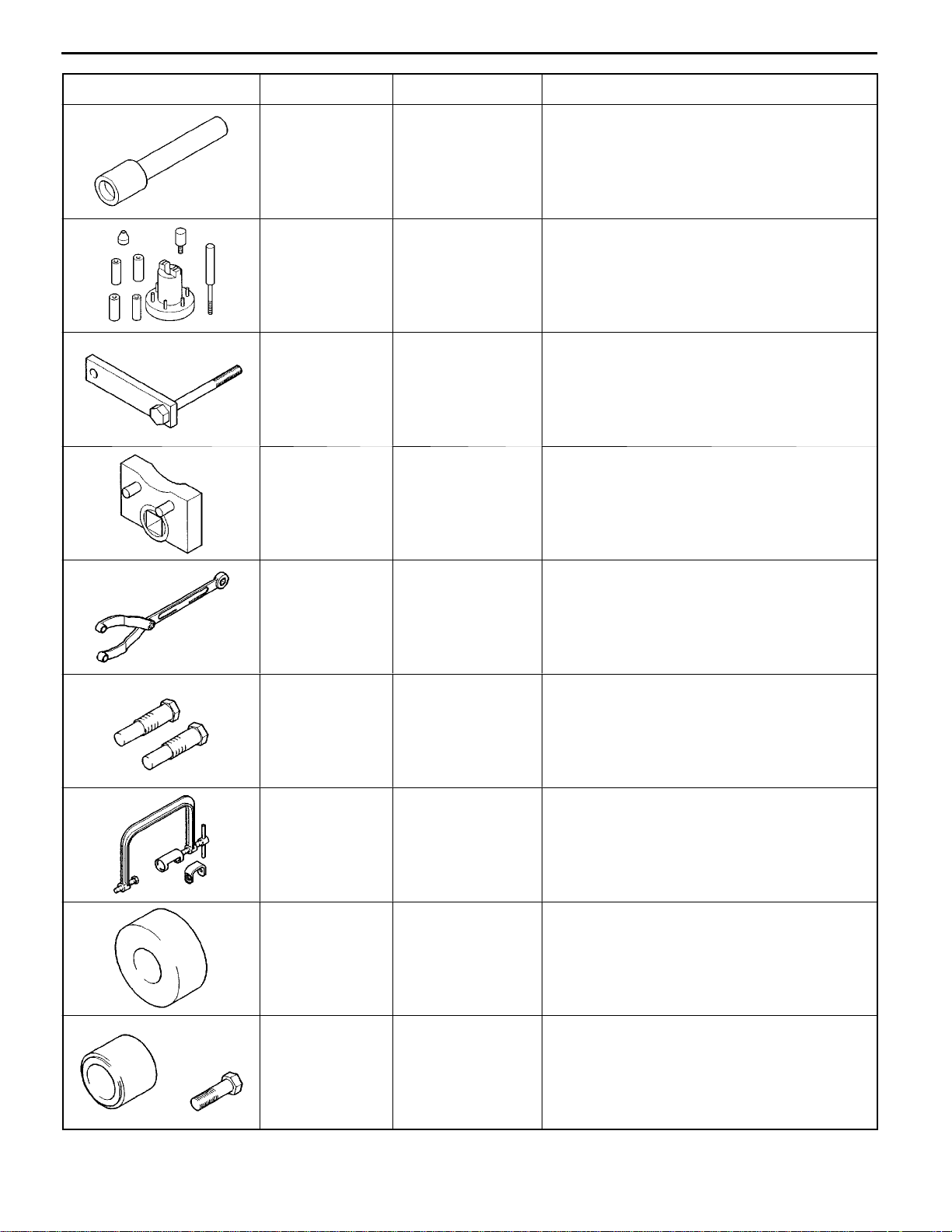
2. SPECIAL TOOLS
Tool Number Name Use
11A-2-1
MB991559 Camshaft oil seal
installer adaptor
MD998051 Cylinder head bolt
wrench
MD998440 Leak-down tester Leak-down test of lash adjuster
MD998441 Lash adjuster Air bleeding of lash adjuster retainer
Installation of camshaft oil seal (on left bank)
(Used in combination with MD998713)
Loosening and tightening of cylinder head bolt
MD998442 Air bleed wire Air bleeding of lash adjuster
MD998443 Auto-lash adjuster
holder
MD998717 Crankshaft front oil
seal
MD998718 Crankshaft rear oil
seal installer
Holding of the lash adjuster to prevent it from
falling when rocker shaft assembly is removed
or installed
Installation of crankshaft front oil seal installer
Press fitting crankshaft rear oil
MD998772 Valve spring
compressor
E
Dec. 1996Mitsubishi Motors Corporation
PWEE9615
Compressing of the valve springs
Page 11
11A-2-2
Tool UseNameNumber
6G7 ENGINE (E-W) -
Special Tools
MD998774 Valve stem seal
installer
MD998780 Piston pin setting
tool
MD998781 Flywheel stopper Holding flywheel or drive plate
MD998767 Tensioner pulley Adjustment of timing belt tension
Installation of valve stem seal
Removal and installation of piston pin
MB990767 End yoke holder Holding camshaft sprocket
(Used in combination with MD998715)
MD998715 Pulley holder pin Holding camshaft sprocket
(Used in combination with MB990767)
MD998735 Valve spring
compressor
adaptor
MD998769 Crank pulley
spacer
Compressing the valve springs
Cranking the crankshaft to install timing belt
MD998713 Camshaft oil seal
installer
E
Dec. 1996Mitsubishi Motors Corporation
PWEE9615
Installation of camshaft oil seal
Page 12
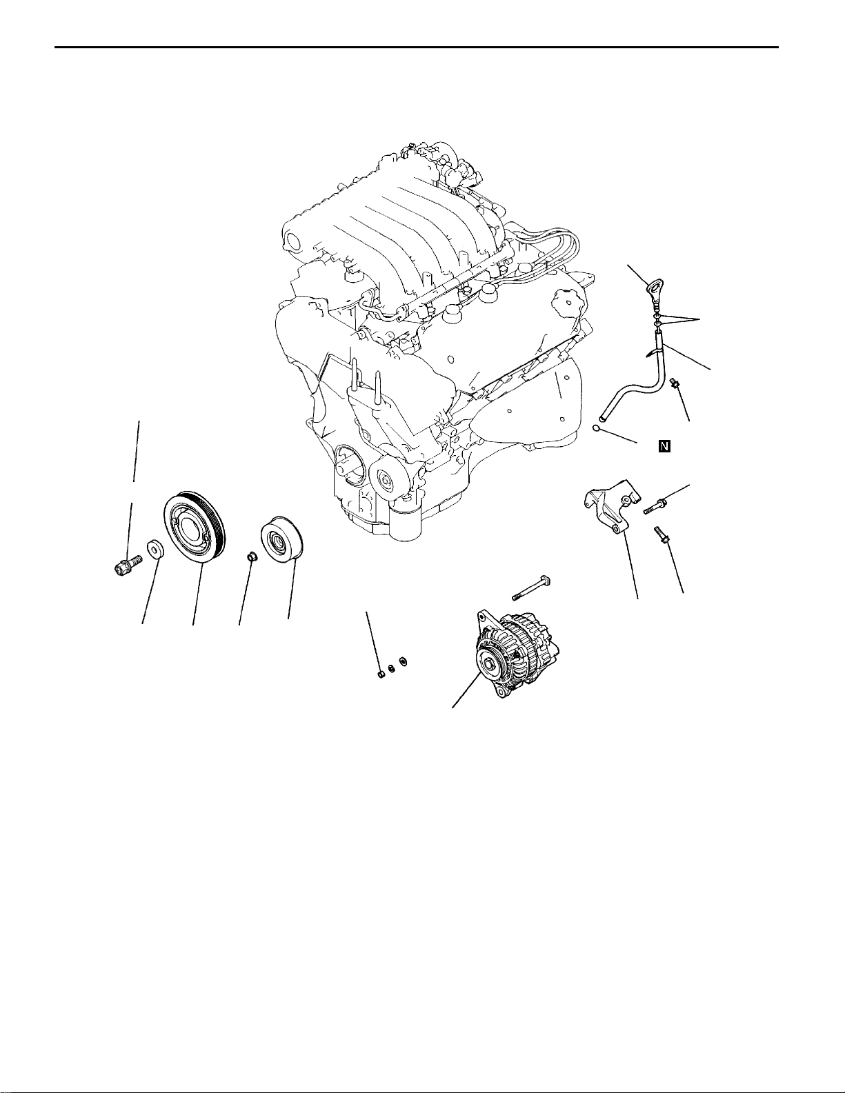
6G7 ENGINE (E-W) -
3. ALTERNATOR
REMOVAL AND INSTALLATION
181 Nm
Alternator
11A-3-1
7
8
9
13 Nm
10
AA""AA
2
3
4
Removal steps
1. Tensioner pulley
2. Crankshaft bolt
3. Washer
4. Crankshaft pulley
5. Alternator
49 Nm
21 Nm
44 Nm
48 Nm
6
1
5
7EN1030
6. Alternator bracket
7. Dip stick
8. O-ring
9. Dip stick tube
10. O-ring
E
Dec. 1996Mitsubishi Motors Corporation
PWEE9615
Page 13
11A-3-2
6G7 ENGINE (E-W) -
Alternator
MD998781
7EN0856
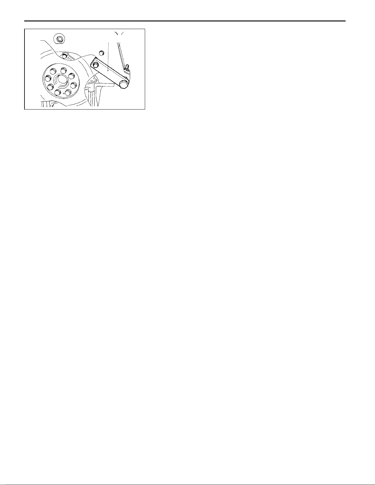
REMOVAL SERVICE POINTS
AA"
(1) With the Special Tool fixed to the drive plate or flywheel
CRANKSHAFT BOLT
remove the crankshaft bolt.
INSTALLATION SERVICE POINTS
"AA
(1) With the Special Tool fixed to the drive plate or flywheel
CRANKSHAFT BOLT
install the crankshaft bolt.
E
Dec. 1996Mitsubishi Motors Corporation
PWEE9615
Page 14

6G7 ENGINE (E-W) -
4. AIR INTAKE PLENUM
REMOVAL AND INSTALLATION
17 Nm
Air Intake Plenum
10
11
11A-4-1
11 Nm
9
21 Nm
17 Nm
17 Nm
4Nm
2
3
17 Nm
4
1
5
12
35 Nm
11 Nm
13
7
6
56 Nm
8
7EN1031
Removal steps
1. Air intake plenum stay, front
2. Air intake plenum stay, rear
3. Accelerator cable bracket
4. EGR valve
5. EGR valve gasket
6. EGR pipe
7. EGR pipe gasket
E
Dec. 1996Mitsubishi Motors Corporation
PWEE9615
"AA
8. Connector bracket
9. Vacuum pipe
10. Throttle body
11. Throttle body gasket
12. Air intake plenum
13. Air intake plenum gasket
Page 15

11A-4-2
Protrusion
6G7 ENGINE (E-W) -
INSTALLATION SERVICE POINTS
"AA
(1) Install gasket with protrusion as illustrated.
6AE0277
THROTTLE BODY GASKET
Air Intake Plenum
E
Dec. 1996Mitsubishi Motors Corporation
PWEE9615
Page 16
6G7 ENGINE (E-W) -
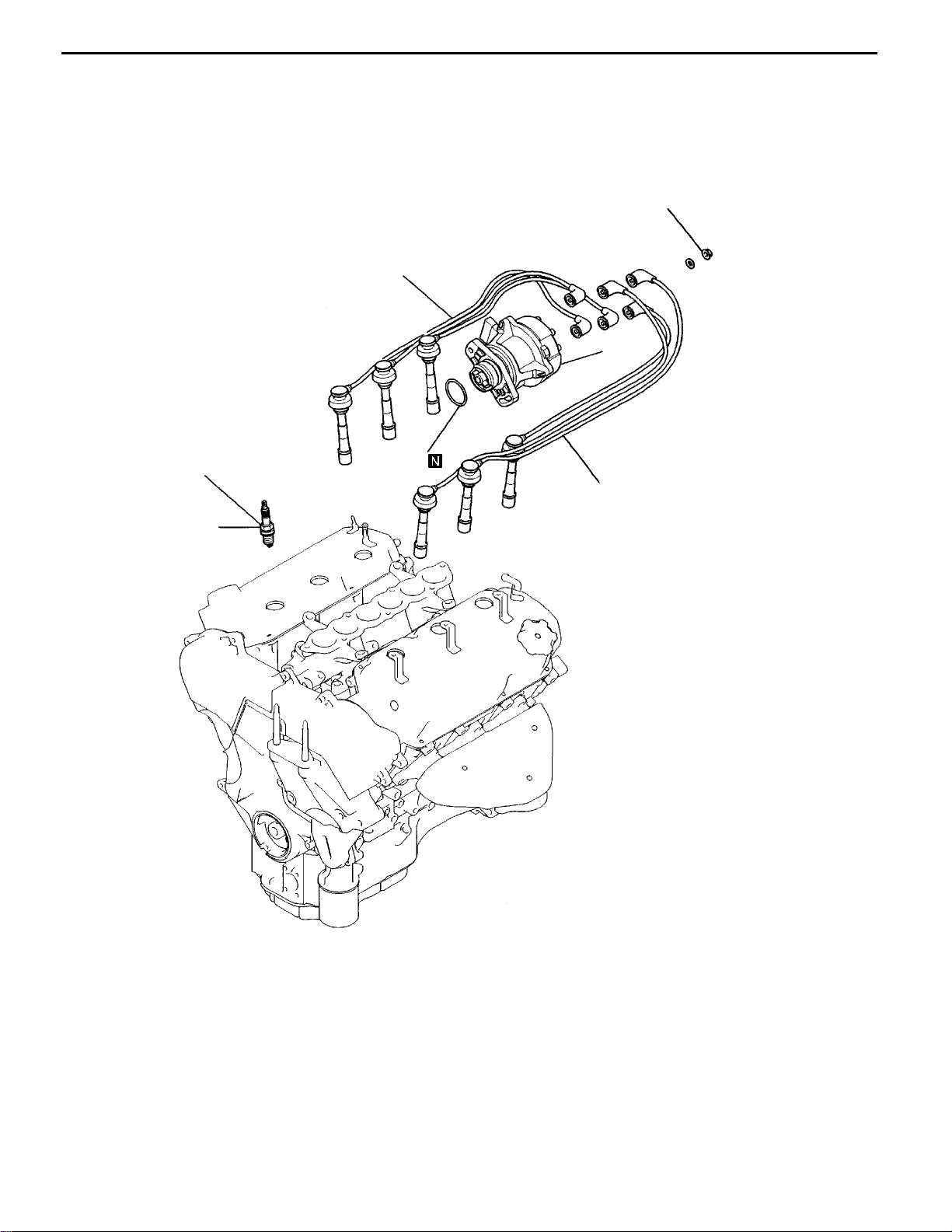
5. IGNITION SYSTEM
REMOVAL AND INSTALLATION
Ignition System
23 Nm
11A-5-1
1
3
25 Nm
2
4
1
7EN0965
Removal steps
1. Spark plug cable
2. Spark plug
3. Distributor
4. O-ring
E
Dec. 1996Mitsubishi Motors Corporation
PWEE9615
Page 17
6G7 ENGINE (E-W) -
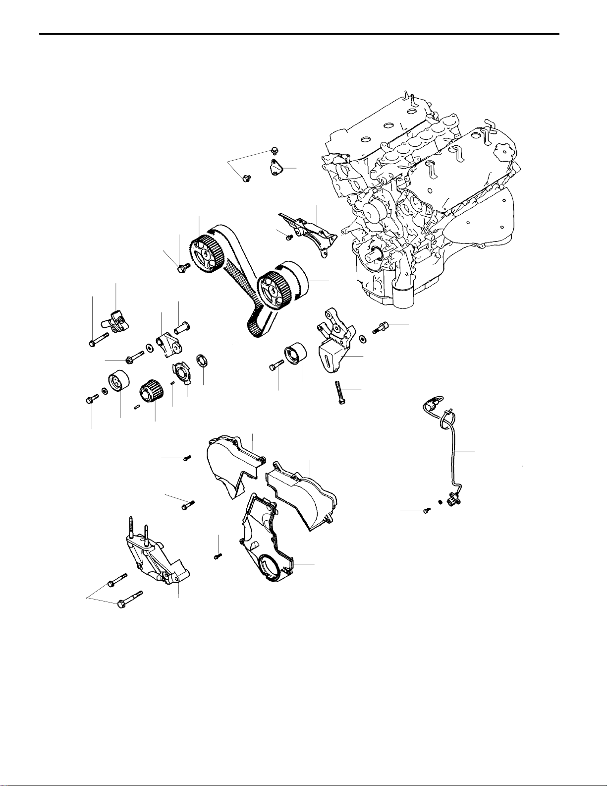
6. TIMING BELT
REMOVAL AND INSTALLATION
Timing Belt
11A-6-1
23Nm
44 Nm
48 Nm
23 Nm
21
22
20
19
88 Nm
7
13 Nm
6
10
9
14
12
16
17
44 Nm
11
13
18
8
15
1
44 Nm
"DA
AA""CA
"BA
E
11 Nm
13 Nm
11 Nm
4
Removal steps
1. Timing belt front upper cover, rear
2. Timing belt front upper cover, front
3. Timing belt front lower cover
4. Engine support bracket
5. Crank angle sensor
6. Timing belt
7. Automatic tensioner
8. Tensioner pulley
9. Tensioner arm
10. Shaft
11. Idler pulley
Dec. 1996Mitsubishi Motors Corporation
2
PWEE9615
3
AB""AA
5
9Nm
7EN0862
12. Idler pulley adjusting bracket
13. Adjusting bolt
14. Adjusting stud
15. Crankshaft sprocket
16. Sensing blade
17. Crankshaft spacer
18. Crankshaft key
19. Camshaft sprocket bolt
20. Camshaft sprocket
21. Bracket
22. Timing belt rear cover
Page 18

11A-6-2
MB990767
6G7 ENGINE (E-W) -
MD998715
7EN0145
Timing Belt
REMOVAL SERVICE POINTS
AA"
(1) When the timing belt is to be reused, in order to allow
AB"
(1) Using the Special Tool, hold the camshaft sprocket.
(2) Remove the camshaft sprocket bolt.
TIMING BELT
re-installation of the belt so that it travels in the same
direction as before it was removed, mark the direction
of travel with an arrow before removing it.
Caution
D
As water or oil on the belt can seriously reduce
itsusable life, ensurethatthetiming belt, sprocket,
and tensioner stay clean and dry while removed,
and never wash them. Parts that have become
too dirty should be replaced.
D
Whenanyofthepartsareoily,checktoseewhether
there are any oil leaks in any of the oil seals or
the camshaft oil seal on the front of the engine.
CAMSHAFT SPROCKET BOLT
Peeling
Cracks
7EN0005
8EN0066
Cracks
Cracks
1EN0249
INSPECTION
TIMING BELT
Check the belt in detail. If th e following is evident, replace
the belt.
(1) Hardened back surface rubber.
Back surface glossy, non-elastic and so hard that even
if a finger nail is forced into it, no mark is produced.
(2) Cracked back surface rubber.
(3) Cracked or separated canvas.
(4) Cracked tooth bottom.
(5) Cracked side of belt.
(6) Side of belt badly worn.
NOTE
Rounded edge
Normal belt should have clear-cut sides as if cut with
a sharp knife.
Abnormal wear
(Fluffy strand)
8EN0067
E
Dec. 1996Mitsubishi Motors Corporation
PWEE9615
Page 19

Rubber exposed
Tooth missing
and canvas fiber
exposed
“L”
6G7 ENGINE (E-W) -
(7) Badly worn teeth.
Initial stage:
Canvas is worn (fluffy canvas fibres are visible, rubber
is gone and colour has changed to white. Canvas texture
is not clear).
Last stage:
Canvas is worn out and rubber exposed an d its width
is reduced.
(8) Missing tooth.
8EN0068
AUTO-TENSIONER
(1) Check for oil leaks. If oil leaks are evident, replace the
auto-tensioner.
(2) Check the rod end for wear or damage and replace the
auto-tensioner if necessary.
(3) Measure the rod projection length “L”. If the reading is
outside the standard value, replace the auto-tensioner.
Standard value “L”: 12 mm
Timing Belt
11A-6-3
MB990767
98 - 196 N
Stroke
MD998715
6AE0046
6EN1033
7EN0005
(4) Press the rod by a force of 98 to 196 N and measure
the rod stroke. If the measured value exceeds the standard
value, replace the tensioner.
Standard value “L”: 1 mm or less
INSTALLATION SERVICE POINTS
"AA
(1) Using the Special Tool, hold the camshaft sprocket.
(2) Torque the camshaft sprocket bolt to the specified torque.
CAMSHAFT SPROCKET BOLT
"BA
AUTO-TENSIONER
(1) If the auto-tensioner rod is fully extended, set it in the
retracted position by the following procedure.
1 Set the auto-tensioner in a vice, making sure it is
not tilted.
7EN0225
E
Dec. 1996Mitsubishi Motors Corporation
PWEE9615
Page 20

11A-6-4
6G7 ENGINE (E-W) -
Timing Belt
A
B
7EN0227
Timing mark
Crankshaft sprocket
Right bank Left bank
Timing mark
7EN0741
2 Slowly close the vice to force the rod in until the set
hole
of the cylinder.
of the rod is lined up with the set hole
(A)
(B)
3 Insert a metal wire (1.4 mm in diameter) into the set
holes.
4 Remove the auto-tensioner from the vice.
(2) Install the auto tensioner on the cylinder block through
the oil pump case.
"CA
(1) Turn the crankshaft sprocket to position its timing mark
(2) Align the timing marks for the left bank camshaft sprocket.
(3) Align the timing marks for the right bank camshaft sprocket.
TIMING BELT
3 teeth away from the timing mark on the crankcase. (That
is, slightly lower the No. 1 piston from the top dead centre
on the compression stroke.)
Caution
D
If the camshaft sprocket is turned with the piston
at the top dead centre on the compression stroke,
valves may interfere with the piston.
Caution
D
The camshaft sprocket may turn un-intentionally
due to the valve spring tension. Take care not
to injure your fingers.
Crankshaft sprocket
Crankshaft sprocket
Tensioner pulley
Timing mark
7EN0742
7EN0740
(4) Align timing marks for the crankshaft sprocket.
(5) Install the timing belt over the sprockets in the following
sequence.
1 Place the timing belt over the crankshaft. While
applying tension to the belt, set it over the idler pulley.
2 Place the belt over the left bank camshaft sprocket.
3 While applying tension to the belt, place it over the
water pump pulley.
4 Place the belt over the right bank camshaft sprocket.
5 Place the belt over the tensioner pulley.
(6) While pressing the tensioner pulley lightly against the
timing belt, temporarily tighten its centre bolt.
(7) Check that all timing marks are in alignment.
7EN0743
E
Dec. 1996Mitsubishi Motors Corporation
PWEE9615
Page 21

6G7 ENGINE (E-W) -
Timing Belt
(8) Using the Special Tool, turn the crankshaft counter-
clockwise a quarter turn, then turn it clockwise and align
the timing marks. Make sure that all timing marks are
in alignment.
MD998769
7EN0744
Right bank Left bank
Timing mark
Water pump
pulley
11A-6-5
Camshaft sprocket
Auto-tensioner
Camshaft sprocket
Tensioner pulley
Idler pulley
Crankshaft sprocket
Timing mark
7EN0745
E
Dec. 1996Mitsubishi Motors Corporation
PWEE9615
Page 22

11A-6-6
MB998767
6G7 ENGINE (E-W) -
(9) Set the Special Tool an d a torque wrench on the tensioner
pulley.
(10)Torque the tensioner pulley to 4.4 Nm.
(11)While holding the tensioner pulley, tighten its centre bolt
to the specified torque.
(12)Turn the crankshaft 2 turns clockwise and let it stand
for approx. 5 minutes.
(13)Remove the wire, which was inserted when installing the
tensioner, from the auto tensioner. If it can be removed
easily, the timing belt tension is correct. Make sure that
7EN0746
the auto tensioner rod projection is within specification.
Standard value: 3.8 - 5.0 mm
(14)If the wire cannot be removed easily or the rod protrusion
is not to specification, repeat steps 9 through 12 to obtain
the correct tension.
Timing Belt
7EN0747
7EN0873
"DA
ENGINE SUPPORT BRACKET
(1) Tighten bolts to specified torque in the sequence shown.
E
Dec. 1996Mitsubishi Motors Corporation
PWEE9615
Page 23

6G7 ENGINE (E-W) -
7. INTAKE MANIFOLD
REMOVAL AND INSTALLATION
Intake Manifold
11A-7-1
17
21 Nm
9Nm
14
11
10
1
11 Nm
18 Nm
2
19
20
9Nm
12
4
5
21
18
8
18 Nm
18 Nm
24
26
23
18 Nm
25
9
7
6
3
13 Nm
13
14
31
27
29
22
28
18 Nm
15
16
11 Nm
29 Nm
"HA
"GA
"FA
"EA
Removal steps
1. Engine harness
2. Injector and delivery pipe
3. Insulator
4. Fuel pressure regulator
5. O-ring
6. Insulator
7. Injector
8. O-ring
9. Grommet
10. Fuel pipe
11. O-ring
12. Delivery pipe
13. Intake manifold
14. Intake manifold gasket
15. Engine coolant temperature gauge
unit
30
"DA
"CA
"AA
"CA
"AA
"BA
"AA
"AA
7EN0874
16. Engine coolant temperature sensor
17. Water hose
18. Water hose
19. Heater inlet pipe
20. O-ring
21. Heater inlet pipe
22. O-ring
23. Water outlet fitting
24. Water outlet fitting gasket
25. Water inlet fitting
26. Thermostat
27. Thermostat housing
28. Thermostat housing gasket
29. O-ring
30. Water pipe
31. O-ring
E
Dec. 1996Mitsubishi Motors Corporation
PWEE9615
Page 24

11A-7-2
6G7 ENGINE (E-W) -
Intake Manifold
Water pump
Water inlet pipe
Jiggle valve
Outlet pipe
O-ring
6EN0594
7EN0876
INSTALLATION SERVICE POINTS
"AA
(1) Wet the O-ring (with water) to facilitate assembly.
"BA
(1) Install the thermostat in the thermostat case with its jiggle
"CA
(1) Attach the outlet an d inlet pipes in this order, one on the
O-RING / WATER PIPE
Caution
D
Keep the O-ring of oil or grease.
THERMOSTAT
valve located at t he top position.
HEATER INLET AND OUTLET PIPES
top of the other.
Sealant
Inlet pipe
Surge tank stay
7EN0877
9EN0091
"DA
APPLICATION OF SEALANT TO ENGINE
COOLANT TEMPERATURE SENSOR
Specified sealant:
3M Nut Locking Part No. 4171 or equivalent
"EA
SEALANT APPLICATION TO ENGINE COOLANT
TEMPERATURE GAUGE UNIT
Specified sealant:
3M ATD Part No. 8660 or equivalent
1EN0338
E
Dec. 1996Mitsubishi Motors Corporation
PWEE9615
Page 25

6G7 ENGINE (E-W) -
Intake Manifold
11A-7-3
Front
7IN0090
7FU0611
"FA
INTAKE MANIFOLD
(1) Tighten the nuts on the right bank to 5 - 8 Nm.
(2) Tighten the nuts on the left bank to the specified torque.
Then tighten the nuts on right bank to the specified torque.
(3) Tighten the nuts on the left bank and those on the right
bank again in that order.
"GA
INJECTOR
(1) Apply a small amount of engine oil to the O-ring.
Caution
D
Take care to prevent the engine oil from entering
the delivery pipe.
(2) Install the injector into the delivery pipe and turn it right
and left.
(3) Make sure the injector turns smoothly. If not, the O-ring
may be caught. Remove the injector and check for damage
to the O-ring, then re-insert it and confirm that it turns
smoothly.
(4) When installing the injector, set the delivery pipe setting
mark and the injector projecting portion.
Setting
mark
Projection portion
6AE0062
"HA
FUEL PRESSURE REGULATOR
(1) Apply a small amount of new engine oil to the O-ring,
then insert the fuel pressure regulator into the delivery
pipe, taking care not to damage the O-ring.
Caution
D
Take care to prevent engine oil from entering the
delivery pipe.
(2) Make sure the regulator turns smoothly. If not, the O-ring
may be caught. Remove the regulator and check for
damage to the O-ring, then re-insert it into the delivery
pipe and confirm that it turns smoothly.
E
Dec. 1996Mitsubishi Motors Corporation
PWEE9615
Page 26

6G7 ENGINE (E-W) -
Exhaust Manifold & Water Pump
8. EXHAUST MANIFOLD & WATER PUMP
REMOVAL AND INSTALLATION
13 Nm
1
11A-8-1
49 Nm
41 Nm
23 Nm
2
3
5
35 Nm
13 Nm
4
9
7
6
8
49 Nm
7EN0966
Removal steps
1. Heat protector, rear
2. Exhaust manifold, rear
"BA
E
3. Exhaust manifold gasket, rear
4. Heat protector, front
5. Engine lift bracket
Dec. 1996Mitsubishi Motors Corporation
PWEE9615
"BA
"AA
6. Exhaust manifold, front
7. Exhaust manifold gasket, front
8. Water pump
9. Water pump gasket
Page 27

11A-8-2
6G7 ENGINE (E-W) -
Exhaust Manifold & Water Pump
Water pump
Water inlet pipe
For right bank
1 3 5
Front
Cylinder No.
O-ring
6EN0594
71N0010
INSTALLATION SERVICE POINTS
"AA
(1) Wet the O-ring (with water) to facilitate assembly.
"BA
(1) Install gaskets with number
(2) Torque the nuts to 30 Nm.
O-RING / WATER PIPE
Caution
D
Keep the O-ring free of oil grease.
EXHAUST MANIFOLD GASKET
1, 3 and 5 embossed on their
top side to the right bank (exhaust manifold (B) side) and
install those with number
manifold (A) side).
2, 4and 6to the left bank (exhaust
Front
For left bank
Cylinder No.
7EN0593
E
Dec. 1996Mitsubishi Motors Corporation
PWEE9615
Page 28

6G7 ENGINE (E-W) -
Rocker Arms and Camshaft
9. ROCKER ARMS AND CAMSHAFT
REMOVAL AND INSTALLATION
11A-9-1
3.4 Nm
2
5
3
11
1
31 Nm
6
10
9
8
9
8
9
8
7
7
7
12
12
13
12 Nm
12
14
15
16
4
Removal steps
1. Rocker cover
2. Gasket
3. Oil seal
"EA 4. Oil seal
AA" 5. Rocker arms, Rocker arm shaft
AA" 6. Rocker arms, Rocker arm shaft
"DA 7. Rocker shaft spring
8. Rocker arm “A”
9. Rocker arm “B”
17
Apply engine oil to all
moving parts before
installation.
7EN0879
"CA 10. Rocker arm shaft
"BA 11. Lash adjuster
12. Rocker arm “C”
"CA 13. Rocker arm shaft
"BA 14. Lash adjuster
15. Thrust case (left bank)
16. O-ring (left bank)
"AA 17. Camshaft
E
Dec. 1996Mitsubishi Motors Corporation
PWEE9615
Page 29

11A-9-2
6G7 ENGINE (E-W) -
MD998443
6AE0160
9EN0058
Rocker Arms and Camshaft
REMOVAL SERVICE POINTS
AA"
(1) Before removing the rocker arms and rocker arm shafts,
LASH ADJUSTER
install the Special Tools to prevent th e lash adjusters from
falling off.
INSPECTION
CAMSHAFT
(1) Measure the cam height.
Standard value:
IN: 37.71 mm
EX: 37.14 mm
Limit:
IN: 37.21 mm
EX: 36.64 mm
MD998440
Diesel fuel
7EN0721
Graduation
(1 mm)
LASH ADJUSTER LEAK DOWN TEST
Caution
D
The lash adjuster is a precision part. Keep it free from
dust and other foreign matters.
D
Do not disassemble lash adjuster.
When cleaning lash adjuster, use clean diesel fuel
only.
(1) Immerse th e lash adjuster in clean diesel fuel.
(2) While lightly pushing down inner steel ball using the Special
Tool (Air bleed wire MD998442), move the plunger up
and down four or five times to bleed air.
Use of the Special Tool (Retainer MD998441) helps
facilitate the air bleeding of the rocker arm mounted type
lash adjuster.
(3) Remove the Special Tool (Air bleed wire MD998442) and
press the plunger. If the plunger is hard to be pushed
in, the lash adjuster is normal. If the plunger can be pushed
in all the way readily, bleed the lash adjuster again and
test again if the plunger is still loose, replace the lash
adjuster.
Caution
D
Uponcompletionofairbleeding,holdlashadjuster
upright to prevent inside diesel fuel from spilling.
(4) After air bleeding, set lash adjuster on the Special Tool
(Leak down tester MD998440).
(5) After plunger has gone down between 0.20 to 0.50 mm,
measure time taken for it to go down a further 1 mm.
Replace if measured time is out of specification.
Standard value: 4 - 20 seconds/1 mm
<Diesel fuel at 15 - 20_C>
Lash adjuster
E
Dec. 1996Mitsubishi Motors Corporation
8EN0059
PWEE9615
Page 30

6G7 ENGINE (E-W) -
INSTALLATION SERVICE POINTS
"AA
(1) Before attaching the camshafts, apply engine oil to the
Slot
7EN0708
Rocker Arms and Camshaft
11A-9-3
CAMSHAFT
journals and cams.
Take care not to confuse the right bank and left bank
camshafts.
NOTE
The right bank camshaft has 4-mm-wide slits in the rear
end surface.
Right bank Left bank
Approx
60
_
MD998442
Approx
71
MD998443
(2) Make sure the camshaft dowel pin is at the location shown.
_
7EN0709
"BA
LASH ADJUSTER
(1) Immerse the lash adjuster in clean diesel fuel No. 2.
(2) While pushing down the inside steel ball with the special
air bleeding wire tool, move the plunger up a n d down
four or five times to evacuate air from the lash adjuster.
7EN0721
(3) Taking care not to spill the diesel fuel, install the lash
adjuster into the rocker arm and attach a special tool to
prevent it from falling out.
Lash adjuster
Timing belt side
Chamfered
E
Oil hole
7EN0722
"CA
ROCKER ARM SHAFT
(1) The end with the larger chamfer is at the right on the
front bank and at the left on the rear bank.
NOTE
The side with the four bolt holes is on the intake side.
(2) The side with the oil holes is on the lower side (cylinder
head side).
9EN0511
Dec. 1996Mitsubishi Motors Corporation
PWEE9615
Page 31

11A-9-4
6G7 ENGINE (E-W) -
Rocker Arms and Camshaft
Rocker shaft
spring
MD998713
7EN0723
6AE0164
"DA
ROCKER SHAFT SPRING
(1) Insert the rocker shaft spring at a slant with respect to
the spark plug guide and install it normal to the guide.
"EA
OIL SEAL
Left bank side
MD998713
MB991559
7EN0724
E
Dec. 1996Mitsubishi Motors Corporation
PWEE9615
Page 32

6G7 ENGINE (E-W) -
Cylinder Head and Valves
10. CYLINDER HEAD AND VALVES
REMOVAL AND INSTALLATION
Apply engine oil to all
moving parts before
installation.
11A-10-1
108 Nm
1
2
12
21
22
13
17
6
5
7
14
11
16
3
9
10
15
18
19
20
8
Removal steps
AA" 1. Cylinder head bolt
2. Washer
3. Cylinder head assembly
4. Cylinder head gasket
AB""CA 5. Retainer lock
6. Valve spring retainer
"BA 7. Valve spring
8. Intake valve
AB""CA 9. Retainer lock
10. Valve spring retainer
"BA 11. Valve spring
E
Dec. 1996Mitsubishi Motors Corporation
4
7EN0915
12. Exhaust valve
AC""AA 13. Valve stem seal
14. Valve spring seat
AC""AA 15. Valve stem seal
16. Valve spring seat
17. Intake valve guide
18. Snap ring
19. Exhaust valve guide
20. Intake valve seat
21. Exhaust valve seat
22. Cylinder head
PWEE9615
Page 33

11A-10-2
MD998051
6G7 ENGINE (E-W) -
REMOVAL SERVICE POINTS
AA"
6AE0166
Cylinder Head and Valves
CYLINDER HEAD BOLT
MD998735
7EN0892
MD998772
6AE0167
AB"
RETAINER LOCK
(1) Attach a tag with the cylinder No. and mounting location
to the detached valves, springs and other parts and store
them for reassembly.
AC"
VALVE STEM SEAL
Caution
D
Do not reuse the stem seal.
7EN0444
E
Dec. 1996Mitsubishi Motors Corporation
PWEE9615
Page 34

6G7 ENGINE (E-W) -
INSPECTION
CYLINDER HEAD
(1) Check the cylinder head for water leaks, gas leaks, damage
(2) Completely remove oil, fur, sealer, carbon and the like.
(3) To ensure flatness of the cylinder head bottom surface,
7EN0258
Cylinder Head and Valves
11A-10-3
or cracks before washing it.
After washing the oil passages, blow air through them
to make sure they are not clogged.
measure the distortion of the surface using a straight edge
and a thickness gauge. When the distortion exceeds the
specifications, correct by grinding t he surface.
Standard values of bottom surface distortion:
Within 0.03 mm
Limit: 0.2 mm
Grinding limit: 0.2 mm
Height of the cylinder head: 120 mm
Caution
D
The cylinder head bottom surface may be ground
to within 0.2 mm of the mating cylinder block.
Contact to be at
the centre of the
valve face.
VALVES
(1) When contact between the valve and the valve seat is
improper, unbalanced or nonexistent, correct the valve
seat.
(2) Change the valve when the margin doesn’t meet the
specifications.
Margin
Standard value: Intake 1.0 mm
Exhaust 1.2 mm
Limit: Intake 0.5 mm
6EN0542
Exhaust 0.7 mm
(3) Measure the total length of the valve. If the measured
value is below the limit, change the valve.
Standard value: Intake 112.30 mm
Exhaust 114.11 mm
Limit: Intake 111.80 mm
Exhaust 113.61 mm
VALVE SPRING
(1) Measure the free height of the valve spring. When the
2
_
measured value exceeds the specified limit, change the
valve spring.
Standard value: 51.0 mm
Limit: 50.0 mm
(2) Measure the perpendicularity of the valve spring. When
Free height
the measured value exceeds the specified limit, change
the valve spring.
Standard value: 2_max.
1EN0264
E
Dec. 1996Mitsubishi Motors Corporation
Limit: 4
PWEE9615
_
Page 35

11A-10-4
6G7 ENGINE (E-W) -
Stem outside diameter
Cylinder Head and Valves
VALVE GUIDE
(1) Measure the clearance between the valve guide and the
valve stem. When the clearance exceeds the specified
limit, change the valve guide or the valve or both.
Standard value: Intake 0.02 - 0.04 mm
Exhaust 0.04 - 0.06 mm
Limit: Intake 0.10 mm
Exhaust 0.15 mm
Guide inside diameter
65
_
15
_
44
_
Valve stem
end
Valve
protrusion
Spring seat
surface
44
_
1EN0279
DEN0212
25
_
65
VALVE SEAT
(1) Assemble the valve, and with it pressed down on the
valve seat measure the part of the valve which protrudes
from the spring seat surface. The length measured should
be between the spring seat surface and the valve stem
end. If the measured value exceeds the limit, change the
valve.
Standard value: 49.3 mm
Limit: 49.8 mm
VALVE SEAT RECONDITIONING PROCEDURE
(1) Check the clearance between the valve guide and the
valve, and if necessary, change the valve guide before
correcting the valve seat.
_
(2) Correct so that the valve seat width a nd angle are as
specified in the figure at left.
(3) After making the corrections, apply lapping compound
and adjust the valve and valve seat.
E
0.5 - 1 mm
Cut off
Height of
valve seat
Oversize hole diameter
0.5 - 1 mm
Dec. 1996Mitsubishi Motors Corporation
7EN0273
1EN0274
1EN0275
VALVE SEAT REPLACEMENT PROCEDURE
(1) Cut off the inside of the valve seat to reduce its thickness
before pulling out the valve seat.
(2) Adjust the valve cylinder hole in the cylinder head to the
diameter of the oversize valve seat to be press fitted.
Intake valve seat hole diameter
0.30 O.S. 34.30 - 34.33 mm
0.60 O.S. 34.60 - 34.63 mm
Exhaust valve seat hole diameter
0.30 O.S. 31.80 - 31.83 mm
0.60 O.S. 32.10 - 32.13 mm
(3) When press fitting a valve seat, cool it using liquid nitrogen
so as not to gall the cylinder head inside diameter.
(4) Machine the valve seat.
(5) See “Valve seat reconditioning procedure.”
PWEE9615
Page 36

14.0 mm
6G7 ENGINE (E-W) -
VALVE GUIDE REPLACEMENT PROCEDURE
(1) Remove the snap ring from the exhaust valve guide.
(2) Pull out to the cylinder block side using a press.
(3) Machine the valve guide hole in the cylinder head to match
7EN0726
(4) Press fit the valve guide until the projection is 14.0 mm,
Cylinder Head and Valves
11A-10-5
the oversize valve guide to be press fitted.
Caution
D
Do not press fit another valve guide of the same
size.
Diameter of the valve guide hole
0.05 O.S. 11.05 - 11.07 mm
0.25 O.S. 11.25 - 11.27 mm
0.50 O.S. 11.50 - 11.52 mm
as shown.
NOTE
D Press fit the valve guide from the top surface of the
cylinder head.
D Pay attention to the difference in the valve guide length
(45.5 mm for the intake side valve guide and 50.5
mm for the exhaust side valve guide).
D After press fitting the valve guide, insert a new valve
and check the contact between the valve guide and
the valve.
I.D. Colour
Silver or white
E
I.D. Colour
Black
Intake side Exhaust side
MD998774
Dec. 1996Mitsubishi Motors Corporation
7EN0763
6AE0169
INSTALLATION SERVICE POINTS
"AA
(1) Attach a valve spring seat.
(2) Attach a new stem seal to the valve guide with the Special
VALVE STEM SEAL
Tool.
NOTE
Pay attention to the difference between the intake side
and exhaust side valve stem seals.
Identifying colour at the valve stem seal portion
Intake side: Silver or white
Exhaust side: Black
Caution
D
Do not reuse valve stem seals.
D
Always use the Special Tool to install valve stem
seals. Improper installation will cause oil leaks.
PWEE9615
Page 37

11A-10-6
6G7 ENGINE (E-W) -
Cylinder Head and Valves
Identification
colour
Spring
retainer
Stem seal
Spring seal
6EN0544
MD998735
7EN0892
"BA
VALVE SPRING
(1) Install the valve spring painted red side up.
"CA
VALVE RETAINER LOCK
(1) Using Special Tool install the valve retainer lock.
MD998772
6AE0167
E
Dec. 1996Mitsubishi Motors Corporation
PWEE9615
Page 38

6G7 ENGINE (E-W) -
11. OIL PAN AND OIL PUMP
REMOVAL AND INSTALLATION
Apply engine oil to all
moving parts before
installation.
22
18
21
Oil Pan and Oil Pump
20
11A-11-1
13
41 Nm
23 Nm
3
2
13 Nm
23 Nm
17
9.8 Nm
9.8 Nm
16
19
18 Nm
12
11
15
4
1
14
9.8 Nm
39 Nm
44 Nm
11 Nm
9
5
10
7
9.8 Nm
8
11 Nm
5.9 Nm
6
11 Nm
Removal steps
"GA 1. Oil pressure switch
"FA 2. Oil filter
3. Oil filter bracket
4. Oil filter bracket gasket
5. Drain plug
6. Drain plug gasket
AA""EA 7. Oil pan, lower
8. Cover
AB""DA 9. Oil pan, upper
10. Baffle plate
11. Oil screen
E
Dec. 1996Mitsubishi Motors Corporation
7EN0893
12. Oil screen gasket
13. Baffle plate
14. Plug
15. Relief spring
16. Relief plunger
"CA 17. Oil seal
"BA 18. Oil pump case
19. O-ring
20. Oil pump cover
AC""AA 21. Oil pump outer rotor
AC""AA 22. Oil pump inner rotor
PWEE9615
Page 39

11A-11-2
6G7 ENGINE (E-W) -
REMOVAL SERVICE POINTS
AA"
(1) Apply wood to the oil p an side and remove the oil pan
lower with a plastic hammer.
Oil Pan and Oil Pump
OIL PAN (LOWER)
A
Alignment marks
7EN0564
7EN0565
AB"
OIL PAN (UPPER)
(1) Detach the bolt (1) shown at left.
(2) Detach all other bolts.
1
(3) Screw a bolt into bolt hole
A shown (at both ends) to
remove the oil pan.
Caution
D
Do not use a scraper or special tool to remove
the oil pan.
AC"
OIL PUMP OUTER AND INNER ROTORS
(1) Draw a setting mark on the oil pump outer and inner rotors
to facilitate reassembly.
7EN0509
INSPECTION
OIL PUMP
(1) Check for tip clearance.
Standard value: 0.06 - 0.18 mm
7EN0510
E
Dec. 1996Mitsubishi Motors Corporation
PWEE9615
Page 40

6G7 ENGINE (E-W) -
(2) Check for side clearance.
Standard value: 0.04 - 0.10 mm
7EN0511
(3) Check for body clearance.
Standard value: 0.10 - 0.18 mm
Limit: 0.35 mm
Oil Pan and Oil Pump
11A-11-3
Alignment marks
7EN0512
7EN0509
7EN0767
INSTALLATION SERVICE POINTS
"AA
(1) Install the oil pump outer rotor in the proper direction using
"BA
(1) Remove the old liquid gasket from the cylinder block (oil
(2) Squeeze out about 3 mm of liquid gasket (FIPG) and
OIL PUMP INNER AND OUTER ROTORS
the setting mark drawn on it before disassembly.
Apply engine oil over the entire rotor surface.
OIL PUMP CASE
pump mounting surface) and from the oil pump.
coat the coating surface with it.
Specified sealant:
MITSUBISHI GENUINE Part No. MD970389 or
equivalent
E
Dec. 1996Mitsubishi Motors Corporation
PWEE9615
Page 41

11A-11-4
6G7 ENGINE (E-W) -
Oil Pan and Oil Pump
MD998717
MD998717 Crankshaft
Guide
Oil seal
Oil pump case
7EN0139
7EN0468
"CA
"DA
OIL SEAL
OIL PAN (UPPER)
(1) Clean the gasket coating surfaces of the cylinder block
and the oil pan upper.
(2) Squeeze out a 4 mm bead of liquid gasket and coat the
coating surface with it.
Top view
Flange bolt tightening sequence
41 5
8
14
18
17 13
Bottom view
7
3
26
9
10
11
15
16
12
7EN0568
A
NOTE
During attachment of the oil pan upper, the sealer must
not be expelled from the flange portion of the oil pan
for distance A as shown.
Liquid gasket:
MITSUBISHI GENUINE Part No. MD970389 or
equivalent
E
Dec. 1996Mitsubishi Motors Corporation
PWEE9615
Page 42

6G7 ENGINE (E-W) -
Oil Pan and Oil Pump
11A-11-5
View from above
lower oil pan
Flange bolt tightening sequence
6
2
10
8
5
View from the bottom of the lower oil pan
1
4
9
7
3
7EN0894
Bracket side
Engine oil
"EA
OIL PAN (LOWER)
(1) Clean the gasket coating surfaces of the oil pan upper
and the oil pan lower.
(2) Squeeze out a 4 mm bead of liquid gasket and coat the
coating surface with it.
Liquid gasket:
MITSUBISHI GENUINE Part No. MD970389 or
equivalent
"FA
OIL FILTER
(1) Clean the oil filter attaching surface on the side of the
cylinder block.
(2) Apply engine oil to the O-ring for the oil filter.
(3) Screw in the oil filter and from the point at which the
O-ring contacts the oil filter attaching surface, tighten it
by about one turn (at approx. 14 Nm).
6EN0591
9EN0094
"GA
OIL PRESSURE SWITCH
Sealer: 3M ATD Part No. 8660 or equivalent
NOTE
D Sealermust not extend beyond the tip of the thread portion.
D Take care not to tighten the switch too much.
E
Dec. 1996Mitsubishi Motors Corporation
PWEE9615
Page 43

6G7 ENGINE (E-W) -
Piston and Connecting Rod
12. PISTON AND CONNECTING ROD
REMOVAL AND INSTALLATION
Apply engine oil to all
moving parts before
installation.
11A-12-1
8
6
4
10
7
9
11
12
5
AA""EA
"DA
"CA
E
3
2
51 Nm
1
Removal steps
1. Connecting rod cap nut
2. Connecting rod cap
3. Connecting rod bearing, lower
4. Piston and connecting rod assembly
5. Connecting rod bearing, upper
6. Piston ring No. 1
Dec. 1996Mitsubishi Motors Corporation
PWEE9615
"CA
"BA
AB""AA
7EN0424
7. Piston ring No. 2
8. Oil ring
9. Piston pin
10. Piston
11. Connecting rod
12. Connecting rod cap bolt
Page 44

11A-12-2
6G7 ENGINE (E-W) -
REMOVAL SERVICE POINTS
AA"
(1) Enter the cylinder No. on t he side of the large end of
Cylinder No.
7EN0448
Piston and Connecting Rod
CONNECTING ROD CAP
the connecting rod to facilitate reassembly.
Push rod
Front
mark
Base
Guide B
Guide C
Push rod
Front mark
Guide A:
17.9 mm
Guide A:
18.9 mm
Guide A:
20.9 mm
Guide A:
21.9 mm
7EN0431
AB"
PISTON PIN
The special piston pin setting tool (MD998780) consists of
the parts shown at left.
(1) Insert the special push rod tool from the front marked
(arrow) side of the piston side and attach guide C.
(2) Set the piston and connecting rod assembly to the special
tool piston pin setting base such that the front mark on
the piston faces upward.
(3) Pull out the piston pin with a press.
NOTE
After pulling out the piston pin, place the piston, the piston
pin, and the connecting rod in order for each cylinder
number.
Guide C
Base
7EN0390
E
Dec. 1996Mitsubishi Motors Corporation
PWEE9615
Page 45

Piston ring
6G7 ENGINE (E-W) -
Push in using
the piston
End clearance
7EN0475
7EN0476
Piston and Connecting Rod
11A-12-3
INSPECTION
PISTON RING
(1) Check the clearance between the piston ring and the ring
groove. If it exceeds the specified limit, change the ring
or the piston an d piston ring.
Standard values: No. 1 0.03 - 0.07 mm
No. 2 0.02 - 0.06 mm
Limit: 0.1 mm
(2) Place the piston ring in the cylinder bore, push it in by
applying the piston head side, and make sure it is square.
Then measure the clearance at the ring ends with a
thickness gauge.
Change the piston ring if the clearance at the ring end
is excessive.
Standard values: No. 1 0.30 - 0.45 mm
No. 2 0.45 - 0.60 mm
Oil 0.20 - 0.60 mm
Limit: No. 1 0.8 mm
No. 2 0.8 mm
Oil 1.0 mm
CRANKSHAFT PIN OIL CLEARANCE (PLASTIGAUGE
METHOD)
(1) Drain oil from the crankshaft pin and the connecting rod
bearing.
(2) Place a piece of Plastigauge the length of the bearing
width on the crankshaft pin straight along the pin centre.
(3) Gently place the connecting rod cap on top and tighten
the bolt to the specified torque.
(4) Detach the bolt and gently remove the connecting rod
1EN0246
cap.
(5) Measure the width of the crushed Plastigauge(at the widest
point) using the scale printed on the Plastigauge package.
Standard value: 0.02 - 0.05 mm
Limit: 0.1 mm
E
Dec. 1996Mitsubishi Motors Corporation
PWEE9615
Page 46

11A-12-4
Connecting rod
B
3mm+L
6G7 ENGINE (E-W) -
C
D
Piston
Piston pin
A
7EN0432
Piston and Connecting Rod
INSTALLATION SERVICE POINTS
"AA
(1) Measure the dimensions of the followingparts and portions:
(2) Calculate by substituting each measured value into the
(3) Insert the special push rod tool into the piston pin and
(4) Combine the piston and the connecting rod, matching
(5) Apply engine oil to the outer periphery of the piston pin.
(6) Insert the side of the piston pin guide A attached per
(7) Screw guide B into guide A until they are distance L
(8) Use special tools to set the piston pin to a special tool
(9) Press fit the piston pin with a press. When the load required
PISTON PIN
A: Piston pin mounting portion
B: Distance between piston bosses
C: Piston pin
D: Connecting rod
following equation:
(A - C) - (B - D)
L=
2
attach guide A to it.
their front marks.
Step (3) into the pin hole from the side of the piston
containing the front mark.
(obtained per Step (2) above) plus 3 mm apart as shown.
piston setting base with the front mark of the piston facing
up.
for press fitting the piston pin is below th e standard value,
change the piston pin (piston assembly) or the connecting
rod or both.
Guide B
Front
mark
Standard values: 7,350 - 17,200 N
Guide A
7EN0433
Push rod
Piston pin
Front mark
Guide A
Base
Guide B
7EN0391
E
Dec. 1996Mitsubishi Motors Corporation
PWEE9615
Page 47

6G7 ENGINE (E-W) -
Piston and Connecting Rod
11A-12-5
Side rail end
7EN0451
"BA
OIL RING
(1) Install t he oil ring spacer into the piston ring groove. Next
install the upper side rail into the piston ring groove, and
then install the lower side rail.
NOTE
D There is no distinction between the upper and lower
surfaces of the side rail and spacer.
D The spacer and side rail (new part) are painted the
following colour to enable size identification.
Side rail Identification colour
S.T.D. None
0.50 mm O.S. Blue
1.00 mm O.S. Yellow
(2) The side rail can be inserted easily into the piston groove
by first inserting one end and then pushing the rail into
place while turning it by hand as shown.
Caution
D
The side rail may break if a ring expander is used.
(3) After installation into the piston, make sure the side rail
turns smoothly in either direction.
"CA
PISTON RING NO. 2 / PISTON RING NO. 1
(1) Using piston ring expander, fit No. 2 and then No. 1 piston
ring into position.
NOTE
D Note the difference in shape between No. 1 and No.
Piston ring expander
2 piston rings.
D Install piston rings No. 1 and No. 2 with their side
having marks facing up (on the piston crown side).
7EN0452
Identification mark
Identification mark
E
Dec. 1996Mitsubishi Motors Corporation
Size mark
9EN0524
PWEE9615
Page 48

11A-12-6
6G7 ENGINE (E-W) -
Piston and Connecting Rod
Upper side rail
No. 2 ring gap
and spacer gap
Piston pin
No. 1
Lower side rail
6EN0549
7EN0032
Cylinder
number
"DA
PISTON AND CONNECTING ROD
(1) Liberally coat the circumference of the piston, piston ring,
and oil ring with engine oil.
(2) Arrange the piston ring and oil ring gaps (side rail and
spacer) as shown in the figure.
(3) Rotate the crankshaft so that the crank pin is positioned
at the centre line of the cylinder bore.
(4) Use suitable thread protectors on connecting rod bolts
before inserting piston and connecting rod assembly into
cylinder block.
Care must be taken not to nick crank pin.
(5) Using a suitable piston ring compressor tool, install piston
and connecting rod assembly into cylinder block.
Caution
D
Install the piston with the front mark (arrow mark)
on the top of the piston facing towards the engine
front (timing belt side).
"EA
CONNECTING ROD CAP
(1) Mate the correct bearing cap with the correct connecting
rod by checking with th e alignment marks marked during
disassembly. If a new connecting rod is used which has
no alignment mark, position the notches for locking the
bearing on the same side.
Notches
7EN0453
(2) Check if the thrust clearance in the connecting rod big
end is correct.
Standard value: 0.10 - 0.25 mm
Limit: 0.4 mm
7EN0454
E
Dec. 1996Mitsubishi Motors Corporation
PWEE9615
Page 49

6G7 ENGINE (E-W) -
Crankshaft, Flywheel and Drive Plate
13. CRANKSHAFT, FLYWHEEL AND DRIVE PLATE
REMOVAL AND INSTALLATION
11A-13-1
Apply engine oil to all
moving parts before
installation.
18
15
2
6
11 Nm
8
1
74 Nm
11 Nm
7
74 Nm
3
5
4
16
17
14
11
13
12
10
9
93 Nm
Removal steps
1. Adaptor plate
2. Drive plate
3. Plate
4. Adaptor plate
5. Flywheel
6. Rear plate
"DA 7. Oil seal case
"CA 8. Oil seal
"BA 9. Bearing cap bolt
E
Dec. 1996Mitsubishi Motors Corporation
PWEE9615
"BA 10. Bearing cap
"AA 11. Thrust bearing (A)
"AA 12. Thrust bearing (B)
"AA 13. Crankshaft bearing (lower)
14. Crankshaft
"AA 15. Thrust bearing (B)
16. Thrust bearing (A)
17. Crankshaft bearing (upper)
18. Cylinder block
7EN1032
Page 50

11A-13-2
6G7 ENGINE (E-W) -
Crankshaft, Flywheel and Drive Plate
Plastigauge
7EN0459
7EN0141
INSPECTION
CRANKSHAFT OIL CLEARANCE (PLASTIGAUGE
METHOD)
NOTE
If the oil clearance exceeds the limit, replace the bearing,
and crankshaft if necessary.
This crankshaft oil clearance can be measured easily by using
a plastic gauge, as follows:
1 Remove oil and grease and any other foreign material
from crankshaft journal an d bearing inner surface.
2 Install th e crankshaft.
3 Cut the plastigauge to the same length as the width of
bearing and place it on journal in parallel with its axis.
4 Gently place the crankshaft bearing cap over it a n d tighten
the bolts to the specified torque.
5 Remove the bolts and gently remove the crankshaft
bearing cap.
6 Measure the width of the crushed plastic gauge at its
widest section by using a scale printed on the plastigauge
package.
Standard values: 0.02 - 0.04 mm
Limit: 0.1 mm
12 mm
7EN0460
7EN0461
CYLINDER BLOCK
(1) Visually check for scratches, rust and corrosion. Also use
flaw detecting agents and the like to check for cracks.
If there are any defects, rectify the cylinder block.
(2) Measure th e flatness of the cylinder block top surface
with a straight edge and a thickness gauge. During
measurement, the cylinder block top surface must be free
from gasket pieces and the like.
Standard values: 0.05 mm
Limit: 0.1 mm
(3) Check for scratches or seizure of the cylinder wall. If there
are any defects, correct (bore it a oversize) or change
the cylinder block.
(4) Measure the inside diameter and the ovality of the cylinder.
If the cylinder is overly worn, correct it to a larger size
and change the pistons and the piston rings.
Standard value:
Cylinder inside diameter 91.1 mm
Ovality: 0.01 mm
E
Dec. 1996Mitsubishi Motors Corporation
PWEE9615
Page 51

6G7 ENGINE (E-W) -
Thrust
direction
Piston O.D.
Crankshaft, Flywheel and Drive Plate
11A-13-3
BORING CYLINDER
(1) Oversize pistons to be used should be determined on
the basis of the largest bore cylinder.
Piston size identification
Size Identification mark
0.50 mm O.S. 0.50
1.00 mm O.S. 1.00
6EN0554
NOTE
Size mark is stamped on the piston top.
(2) Measure outside diameter of piston to be used. Measure
it in thrust direction as shown.
(3) Based on the measured piston O.D., calculate the boring
finish dimension.
Boring finish dimension = Piston O.D. + (Clearance
between piston O.D. and cylinder) - 0.02 mm (honing
margin)
(4) Bore all cylinders to the calculated boring finish dimension.
Caution
D
To prevent distortion that may result from
temperature rise during honing, bore cylinders,
in the order of No. 1, No. 2, No. 3, No. 4, No. 5
and No. 6.
(5) Hone to the final finish dimension (Piston O.D. + clearance
between piston O.D. and cylinder.)
(6) Check the clearance between piston and cylinder.
Clearance between piston and cylinder:
0.02 - 0.04 mm
NOTE
When boring cylinders, finish all of four cylinders to the
same oversize. Do not bore only one cylinder to an
oversize.
E
Dec. 1996Mitsubishi Motors Corporation
PWEE9615
Page 52

11A-13-4
6G7 ENGINE (E-W) -
Crankshaft, Flywheel and Drive Plate
Identification colour position
No. 4
No. 3
journal
No. 1
journal
Timing belt side
journal
No. 2
journal
Cylinder bore size mark
No. 2
No. 1
Cylinder block bearing
bore identification mark
No. 3
No. 4
7EN0991
7EN0992
INSTALLATION SERVICE POINTS
"AA
When bearing replacement is required, select and install the
correct bearing by the following procedure.
(1) Measure the crankshaft journal diameter and confirm its
(2) The cylinder block bearing bore diameter identification
CRANKSHAFT BEARING
classification from the following table. In the case of a
crankshaft supplied as a service part, identification
colours/marks of its journals are painted/stamped at the
positions shown in the illustration.
marks are stamped at the position shown in the illustration
from left to right, beginning at No. 1.
Combination of crankshaft journal diameter and cylinder block bearing bore diameter Bearing
identification
Crankshaft journal Cylinder block
bearing bore
Classification Identification colour O.D. mm
diameter
identification
Production part Service part
mark
colour or
identification
mark (for service
part)
1 None Yellow, 0 59.994 - 60.000 I Pink, 1
II Red, 2
III Green, 3
2 None None, 1 59.988 - 59.994 I Red, 2
II Green, 3
III Black, 4
3 None White, 2 59.982 - 59.988 I Green, 3
II Black, 4
III Brown, 5
E
Dec. 1996Mitsubishi Motors Corporation
PWEE9615
Page 53

6G7 ENGINE (E-W) -
Crankshaft, Flywheel and Drive Plate
11A-13-5
Identification
colour
Oil groove
Identification mark
Groove
7EN0600
7EN0602
(3) Select the correct bearing from the above table on the
basis of the identification data confirmed at steps 1 and
2.
Example
D If the measured value of a crankshaft journal outer
diameter is 59.996 mm, the journal is classified as
“1” in the table.
In case the crankshaft is also replaced by a spare
part, check the identification colours of the journals
painted on the new crankshaft. If the colour is yellow,
for example, the journal is classified as “1”.
D Next, check the cylinder block bearing bore
identification mark stamped on the cylinder block. If
it is “1”, read the “Bearing identification colour” column
to find the identification colour of the bearing to be
used. In this case, it is “pink”.
(4) Install the bearing halves with oil groove on the cylinder
block side.
(5) Install t h e bearing halves without oil groove on the bearing
cap side.
(6) Install the thrust bearings on both sides of the No. 3 bearing
with the grooves facing outward.
"BA
BEARING CAP / BEARING BOLT
(1) Attach the bearing cap on the cylinder block as shown
in the figure.
(2) Tighten the bearing cap bolts to the specified torque in
the sequence shown in the figure.
(3) Check that the crankshaft rotates smoothly.
Front mark
Crankshaft
84
7
3
1
2
Bearing cap
Bearing cap bolt
5
6
Cylinder block
7EN0609
E
Dec. 1996Mitsubishi Motors Corporation
PWEE9615
Page 54

11A-13-6
6G7 ENGINE (E-W) -
7EN0034
Crankshaft, Flywheel and Drive Plate
(4) Check the end play. If it exceeds the limit value, replace
the thrust bearing.
Standard value: 0.05 - 0.25 mm
Limit: 0.3 mm
MD998718
Oil seal
case
7EN0465
7EN0467
"CA
CRANKSHAFT REAR OIL SEAL
(1) Using the Special Tool, press-fit a new crankshaft rear
oil seal into the seal case.
"DA
OIL SEAL CASE
(1) Squeeze out a 3 mm bead of liquid gasket (FIPG) and
apply it to the coating surface.
Liquid gasket:
MITSUBISHI GENUINE Part No. MD970389
E
Dec. 1996Mitsubishi Motors Corporation
PWEE9615
Page 55

NOTES
 Loading...