

Page 1

ENGINE
4G1 SERIES
CONTENTS
11A-0-1
GENERAL INFORMATION 11A-0-3
1. SPECIFICATIONS 11A-1-1
SERVICE SPECIFICATIONS 11A-1-1
REWORK DIMENSIONS 11A-1-3
TORQUE SPECIFICATIONS 11A-1-4
NEW TIGHTENING METHOD-BY USE OF BOLTS TO BE
TIGHTENED IN PLASTIC AREA 11A-1-6
SEALANT 11A-1-6
FORM-IN-PLACE GASKET 11A-1-7
2. SPECIAL TOOLS 11A-2-1
3. ALTERNATOR AND IGNITION SYSTEM 11A-3-1
4. TIMING BELT 11A-4-1
5. FUEL AND EMISSION CONTROL SYSTEM 11A-5-1
6. WATER PUMP AND WATER HOSE 11A-6-1
7. INTAKE AND EXHAUST MANIFOLD 11A-7-1
8. ROCKER ARMS AND CAMSHAFT 11A-8-1
........................................................
......................................................
...........................................
.................................................
....................................
........................................
.....................................
...............................
......................................
.................................................
........................
....................
.............................
............................
..............................
9. CYLINDER HEAD AND VALVES 11A-9-1
10. OIL PUMP AND OIL PAN 11A-10-1
11. PISTON AND CONNECTING ROD 11A-11-1
12. CRANKSHAFT, CYLINDER BLOCK 11A-12-1
E
Nov. 1995Mitsubishi Motors Corporation
.......................................
.................................
..............................
...........................
PWEE9520
Page 2

11A-0-2
NOTES
E
Nov. 1995Mitsubishi Motors Corporation
PWEE9520
Page 3
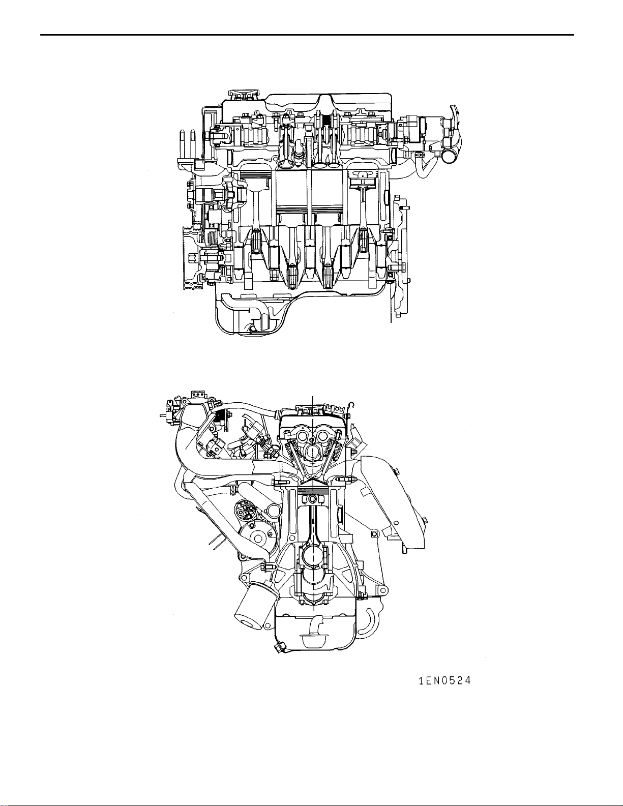
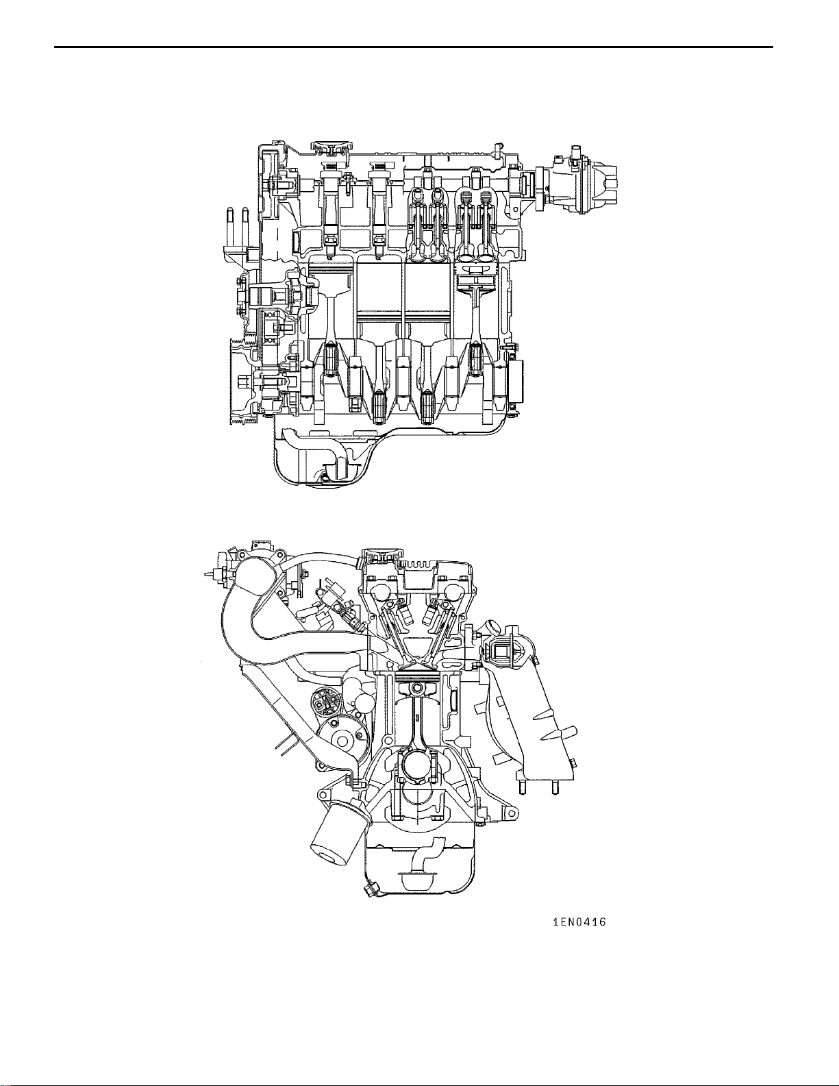
4G1 ENGINE (E-W) -
GENERAL INFORMATION
General Information
11A-0-3
E
Nov. 1995Mitsubishi Motors Corporation
PWEE9520
Page 4
11A-0-4
4G1 ENGINE (E-W) -
General Information
E
Nov. 1995Mitsubishi Motors Corporation
PWEE9520
Page 5
4G1 ENGINE (E-W) -
General Information
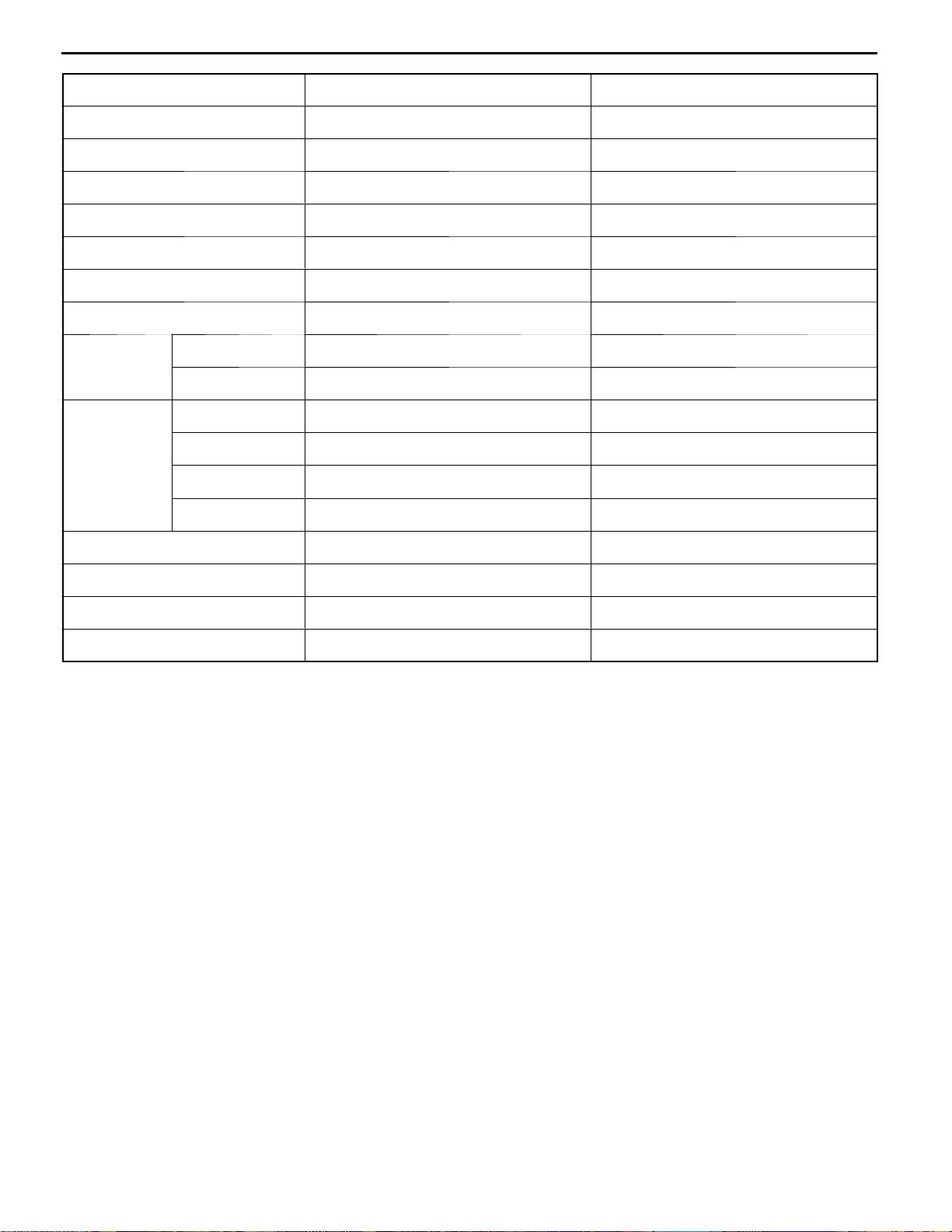
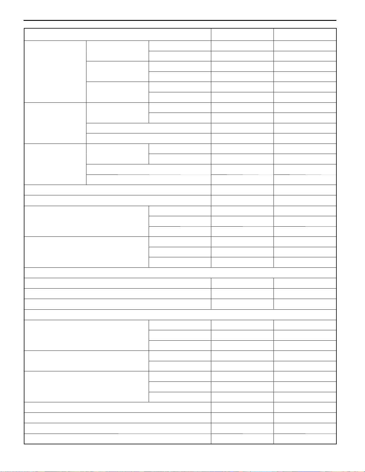
Descriptions 4G13 12-VALVE- CARBURETOR 4G13 12-VALVE- MPI
Type In-line OHV, SOHC In-line OHV, SOHC
Number of cylinders 4 4
Combustion chamber Pentroof type Pentroof type
11A-0-5
Total displacement dm
3
1,299 1,299
Cylinder bore mm 71.0 71.0
Piston stroke mm 82.0 82.0
Compression ratio 9.5 9.5
Number of Intake 8 8
valves
Exhaust 4 4
V alve timing Intake opens BTDC 14
Intake closes ABDC 48
Exhaust opens BBDC 55
Exhaust closes ATDC 13
_
_
_
_
BTDC 19
ABDC 43
BBDC 60
ATDC 8
_
_
_
_
Lubrication system Pressure feed, full-flow filtration Pressure feed, full-flow filtration
Oil pump type Trochoid type Trochoid type
Cooling system Water-cooled, forced circulation Water-cooled, forced circulation
Water pump type Centrifugal impeller type Centrifugal impeller type
E
E
Nov. 1995Mitsubishi Motors Corporation
Dec. 1998Mitsubishi Motors Corporation Revised
PWEE9520
PWEE9520-A
Page 6

11A-0-6
4G1 ENGINE (E-W) -
General Information
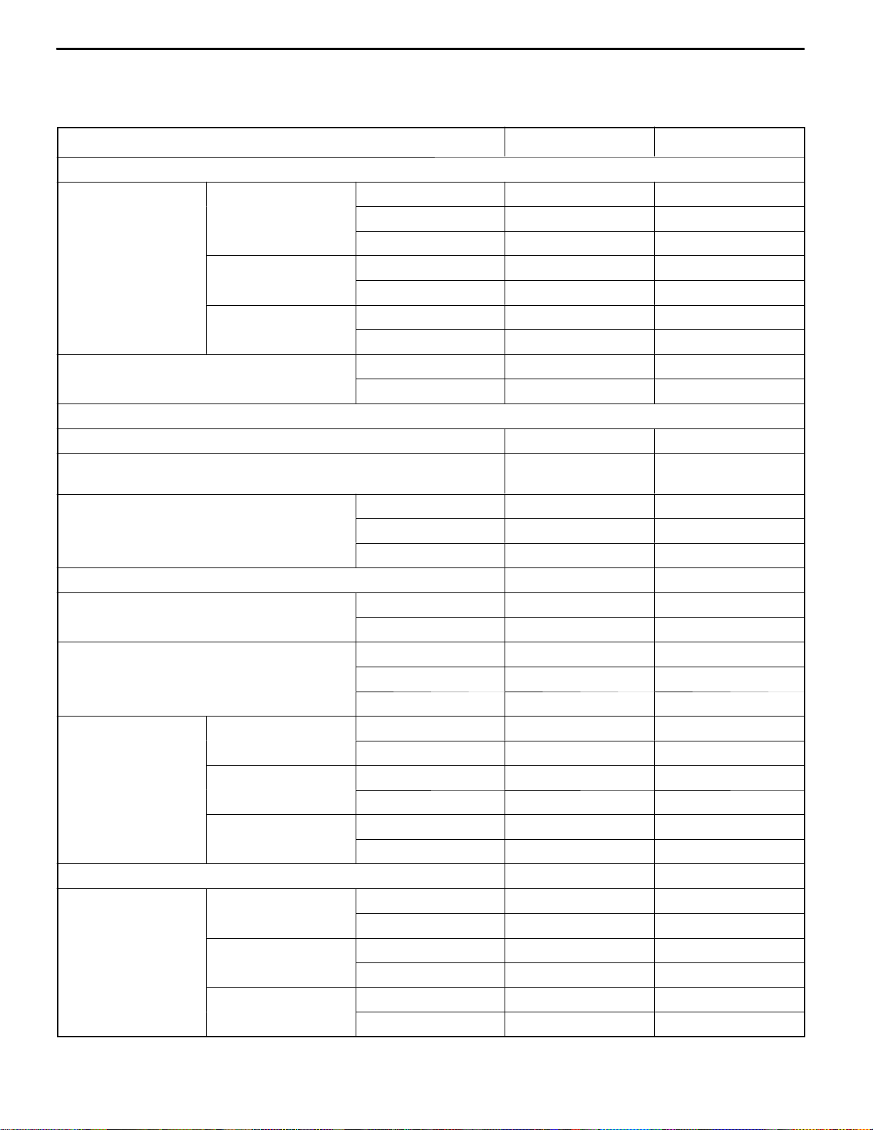
Descriptions 4G13 16-VALVE- MPI 4G18 16-VALVE- MPI
Type In-line OHV, SOHC In-line OHV, SOHC
Number of cylinders 4 4
Combustion chamber Pentroof type Pentroof type
Total displacement dm
3
1,299 1,584
Cylinder bore mm 71.0 76.0
Piston stroke mm 82.0 87.3
Compression ratio 10 9.5
Number of Intake 8 8
valves
Exhaust 8 8
V alve timing Intake opens BTDC 17
Intake closes ABDC 39
Exhaust opens BBDC 49
Exhaust closes ATDC 7
_
_
_
_
BTDC 17
ABDC 39
BBDC 49
ATDC 7
_
_
_
_
Lubrication system Pressure feed, full-flow filtration Pressure feed, full-flow filtration
Oil pump type Trochoid type Trochoid type
Cooling system Water-cooled, forced circulation Water-cooled, forced circulation
Water pump type Centrifugal impeller type Centrifugal impeller type
E
E
Nov. 1995Mitsubishi Motors Corporation
Dec. 1998Mitsubishi Motors Corporation Revised
PWEE9520
PWEE9520-A
Page 7

4G1 ENGINE (E-W) -
General Information
Descriptions 4G15-CARBURETTOR 4G15-MPI
Type In-line OHV, SOHC In-line OHV, DOHC
Number of cylinders 4 4
Combustion chamber Semi spherical type Pentroof type
11A-0-7
Total displacement dm
3
1,468 1,468
Cylinder bore mm 75.5 75.5
Piston stroke mm 82.0 82.0
Compression ratio 9.0 9.5
Number of Intake 8 8
valve
Exhaust 4 8
V alve timing Intake opens BTDC 14
Intake closes ABDC 48
Exhaust opens BBDC 55
Exhaust closes ATDC 13
_
_
_
_
BTDC 16
ABDC 40
BBDC 45
ATDC 15
_
_
_
_
Lubrication system Pressure feed, full-flow filtration Pressure feed, full-flow filtration
Oil pump type Trochoid type Trochoid type
Cooling system Water-cooled, forced circulation Water-cooled, forced circulation
Water pump type Centrifugal impeller type Centrifugal impeller type
E
E
Nov. 1995Mitsubishi Motors Corporation
Dec. 1998Mitsubishi Motors Corporation Added
PWEE9520
PWEE9520-A
Page 8

NOTES
Page 9
4G1 ENGINE (E-W) -
Specifications
1. SPECIFICATIONS
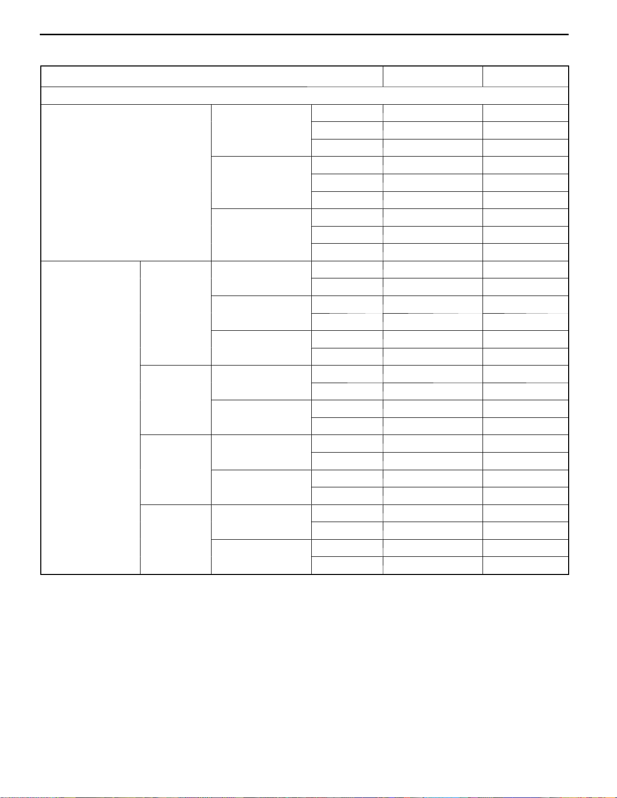
SERVICE SPECIFICATIONS
Item Standard Limit
Rocker arms, rocker shafts, and camshaft
11A-1-1
Camshaft cam SOHC 12-VALVE
height mm
SOHC 16-VALVE
DOHC
Camshaft journal diameter mm
Cylinder head and valves
Flatness of cylinder head gasket surface mm 0.05 or less -
Cylinder head gasket surface grinding limit (including grinding of
cylinder block gasket surface) mm
Cylinder head overall height mm
Cylinder head bolt nominal length mm - 103.2
V alve margin mm
Intake (primary) 38.78 38.28
Intake (secondary) 38.78 38.28
Exhaust 39.10 38.60
Intake 36.99 36.49
Exhaust 36.85 36.35
Intake 34.67 38.28
Exhaust 34.26 38.60
SOHC 45.93- 45.94 -
DOHC 25.95- 25.97 -
- 0.2
SOHC 12-VALVE 106.9- 107.1 -
SOHC 16-VALVE 119.9- 120.1 -
DOHC 131.9- 132.1 -
Intake 1.0 0.5
Exhaust 1.5 1.0
Valve stem diameter mm
V alve stem-to-guide SOHC 12-VALVE
clearance mm
SOHC 16-VALVE
DOHC
V alve face angle 45_- 45.5
V alve stem projec- SOHC 12-VALVE
tion mm
SOHC 16-VALVE
DOHC
SOHC 12-VALVE 6.6 -
SOHC 16-VALVE 5.5 -
DOHC 5.5 -
Intake 0.020- 0.050 0.10
Exhaust 0.050- 0.085 0.15
Intake 0.020 - 0.047 0.10
Exhaust 0.030 - 0.062 0.15
Intake 0.020- 0.047 0.10
Exhaust 0.030- 0.062 0.15
Intake 43.70 44.20
Exhaust 43.30 43.80
Intake 53.21 53.71
Exhaust 54.10 54.60
Intake 48.80 49.30
Exhaust 48.70 49.20
_
-
E
E
Nov. 1995Mitsubishi Motors Corporation
Dec. 1998Mitsubishi Motors Corporation Revised
PWEE9520
PWEE9520-A
Page 10
11A-1-2
4G1 ENGINE (E-W) -
Specifications
Item LimitStandard
Overall valve length SOHC 12-VALVE
mm
SOHC 16-VALVE
Intake 100.75 100.25
Exhaust 101.05 105.55
Intake 111.56 111.06
Exhaust 114.71 114.21
DOHC
Intake 106.35 105.85
Exhaust 106.85 106.35
V alve spring free SOHC 12-VALVE
height mm
Intake 46.1 45.6
Exhaust 46.8 46.3
SOHC 16-VALVE 50.9 50.4
DOHC 49.1 48.6
Valve spring load/ SOHC 12-VALVE
installed height N/
mm
mm
Intake 226/40.0 -
Exhaust 284/39.6 -
SOHC 16-VALVE 216/44.2 -
DOHC 177/40.0 -
Valve spring squareness 2
_
Valve seat contact width mm 0.9- 1.3 -
V alve guide internal diameter mm
SOHC 12-VALVE 6.6 -
_
4
SOHC 16-VALVE 5.5 -
DOHC 5.5 -
Valve guide projection mm
SOHC 12-VALVE 17.0 -
SOHC 16-VALVE 23.0 -
DOHC 23.0 -
Oil pump and oil pan
Oil pump tip clearance mm 0.06- 0.18 -
Oil pump side clearance mm 0.04 - 0.10 -
Oil pump body clearance mm 0.10- 0.18 0.35
Pistons and connecting rods
Piston outside diameter mm
4G13 71.0 -
4G15 75.5 -
4G18 76.0 -
Piston ring side clearance mm
No. 1 ring 0.02- 0.06 -
No. 2 ring 0.02- 0.06 -
Piston ring end gap clearance
No. 1 ring 0.20- 0.35 0.8
No. 2 ring 0.35- 0.50 0.8
Oil ring 0.20- 0.50 1.0
Piston pin O. D. mm 18.0 -
Piston pin press-in load (at room temperature) N 4,900 - 14,700 -
Crankshaft pin oil clearance mm 0.02- 0.04 0.1
Connecting rod big end side clearance mm 0.10- 0.25 0.4
E
E
Nov. 1995Mitsubishi Motors Corporation
Dec. 1998Mitsubishi Motors Corporation Revised
PWEE9520
PWEE9520-A
Page 11
4G1 ENGINE (E-W) -
Specifications
Item Standard Limit
Crankshaft and cylinder block
Crankshaft end play mm 0.05- 0.18 0.25
Crankshaft journal diameter mm 48.0 -
Crankshaft pin diameter mm 42.0 -
Crankshaft journal oil clearance mm 0.02- 0.04 0.1
Cylinder block gasket surface flatness mm 0.05 or less -
11A-1-2a
Cylinder block gasket surface grinding limit (including grinding of
- 0.2
cylinder head gasket surface) mm
Cylinder block overall height mm 256 -
Cylinder block cylindricity mm 0.01 -
Cylinder block I. D. mm
4G13 71.0 -
4G15 75.5 -
4G18 76.0 -
Piston-to-cylinder clearance mm 0.02-0.04 -
E
E
Nov. 1995Mitsubishi Motors Corporation
Dec. 1998Mitsubishi Motors Corporation Added
PWEE9520
PWEE9520-A
Page 12

11A-1-2b
4G1 ENGINE (E-W) -
Specifications
Intentionally blank
E
E
E
Nov. 1995Mitsubishi Motors Corporation
Dec. 1998Mitsubishi Motors Corporation AddedPWEE9520-A
Dec. 1998Mitsubishi Motors Corporation Added
PWEE9520
PWEE9520-A
Page 13
4G1 ENGINE (E-W) -
Specifications
REWORK DIMENSIONS
Item Standard Limit
Cylinder head and valves
11A-1-3
Cylinder head oversize valve guide SOHC 12-VALVE
hole diameter mm
SOHC 16-VALVE
DOHC
Oversize valveseat SOHC Intake (primary)
ring hole diametermm12-VALVE
mm
Intake (secondary)
Exhaust
SOHC Intake
16-VALVE
<4G13>
<4G13>
Exhaust
0.05 O. S. 12.050- 12.068 -
0.25 O. S. 12.250- 12.268 -
0.50 O. S. 12.500- 12.518 -
0.05 O. S. 10.550- 10.568 -
0.25 O. S. 10.750- 10.768 -
0.50 O. S. 11.000 - 11.018 -
0.05 O. S. 10.550- 10.568 -
0.25 O. S. 10.750- 10.768 -
0.50 O. S. 11.000 - 11.018 -
0.3 O. S. 27.300- 27.325 -
0.6 O. S. 27.600- 27.625 -
0.3 O. S. 32.300- 32.325 -
0.6 O. S. 32.600- 32.625 -
0.3 O. S. 35.300- 35.325 -
0.6 O. S. 35.600- 35.625 -
0.3 O. S. 28.300- 28.321 -
0.6 O. S. 28.600- 28.621 -
0.3 O. S. 26.300- 26.321 -
SOHC Intake
16-VALVE
<4G18>
<4G18>
Exhaust
DOHC Intake
Exhaust
0.6 O. S. 26.600- 26.621 -
0.3 O. S. 30.300- 30.321 -
0.6 O. S. 30.600- 30.621 -
0.3 O. S. 28.300- 28.321 -
0.6 O. S. 28.600- 28.621 -
0.3 O. S. 31.300- 31.325 -
0.6 O. S. 31.600- 31.625 -
0.3 O. S. 27.800- 27.825 -
0.6 O. S. 28.100- 28.125 -
E
E
Nov. 1995Mitsubishi Motors Corporation
Dec. 1998Mitsubishi Motors Corporation Revised
PWEE9520
PWEE9520-A
Page 14
11A-1-4
4G1 ENGINE (E-W) -
Specifications
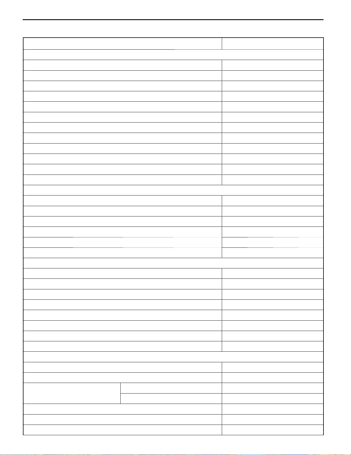
TORQUE SPECIFICATIONS
Item Nm
Alternator and ignition system
Water pump pulley bolt 9
Alternator brace (alternator side) 22
Alternator brace (tightened with water pump) 23
Alternator pivot bolt 44
Oil level gauge guide 23
Crankshaft bolt 125
Spark plug 25
Distributor 11
Ignition coil 10
Camshaft position sensor 9
Camshaft position sensor support 13
Camshaft position sensing cylinder 21
Timing belt
Timing belt cover 11
Timing belt tensioner 23
Crankshaft angle sensor (Rear wheel drive) 9
Engine support bracket (left) 35
Idler pulley 35
Camshaft sprocket bolt 88
Fuel system
Delivery pipe 11
Fuel pressure regulator 9
Throttle body 18
Fuel pump 11
Breather tube 22
Carburetor 17
Air temperature sensor 13
EGR valve 21
Water pump
Water inlet fitting 22
Water inlet pipe assembly 12
Water inlet pipe
M6 12
M8 25
Fitting (Rear wheel drive) 23
Water outlet fitting (Rear wheel drive) 23
Thermostat case 23
E
E
Nov. 1995Mitsubishi Motors Corporation
Dec. 1998Mitsubishi Motors Corporation Revised
PWEE9520
PWEE9520-A
Page 15
4G1 ENGINE (E-W) -
Specifications
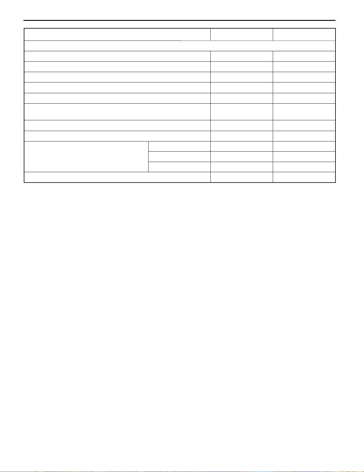
Item Nm
Thermo valve 27
Water temperature gauge unit 11
Water temperature sensor 29
Water pump 13
Exhaust manifold and intake manifold
Boost sensor 5
Solenoid valve assembly 9
Intake manifold 17
11A-1-5
Intake manifold stay (MPI)
M8 17
M10 21
Intake manifold stay (carburetor) 29
Exhaust manifold cover 29
Exhaust manifold
M8 17
M10 29
Oxygen sensor 44
Rocker arms, rocker shafts, and camshaft
Fuel pump cover 12
Rocker cover 4
Rocker shaft assembly 31
Adjusting screw 15
Bearing cap
24
11
Cylinder head and valves
Cylinder head bolt 20 + 90_+90
_
Tighten to 49 Nm, then completely loosen and retighten as described.
Oil pump and oil pan
Transmission stay 23
Oil pan 7
Drain plug 39
Oil screen 18
Front case 13
Relief plug 44
Oil pump cover 10
Pistons and connecting rods
Connecting rod nut 17 + 90_to 100
E
E
Nov. 1995Mitsubishi Motors Corporation
Dec. 1998Mitsubishi Motors Corporation Revised
PWEE9520
PWEE9520-A
_
Page 16

11A-1-5a
4G1 ENGINE (E-W) -
Specifications
Item Nm
Crankshaft and cylinder block
Flywheel 132
Drive plate 132
Rear plate 10
Bell housing cover 10
Rear oil seal case 11
Bearing cap bolt 51
Oil pressure switch 18
Knock sensor 23
E
E
Nov. 1995Mitsubishi Motors Corporation
Dec. 1998Mitsubishi Motors Corporation Added
PWEE9520
PWEE9520-A
Page 17

4G1 ENGINE (E-W) -
Specifications
11A-1-5b
Intentionally blank
E
E
E
Nov. 1995Mitsubishi Motors Corporation
Dec. 1998Mitsubishi Motors Corporation AddedPWEE9520-A
Dec. 1998Mitsubishi Motors Corporation Added
PWEE9520
PWEE9520-A
Page 18
11A-1-6
4G1 ENGINE (E-W) -
Specifications
NEW TIGHTENING METHOD USING PLASTIC REGION TIGHTENING BOLTS
Parts of the engine use plastic region tightening bolts. The tightening procedure for these is different
from that of conventional bolts and is described in relevant parts of this manual. Note that plastic region
tightening bolts have fixed service limits. These limits are indicated in relevant parts of this manual and
must be strictly observed.
Plastic region tightening bolts are used for the following applications:
D
(1) Cylinder head bolts
(2) Connecting rod cap bolts
The tightening procedure is basically as follows:
D
After tightening a bolt to the specified torque, tighten it by a further 90_+90_or by a further 90–100°.
The exact tightening procedure differs depending on the bolt and is described in relevant parts of
this manual.
SEALANTS
Item Specified sealant Quantity
Water pump Mitsubishi Genuine Part No. MD970389 or equivalent As required
Thermo valve Mitsubishi Genuine Part No. MD970389 or equivalent As required
Engine coolant temperature sensor 3M Nut Locking Part No. 4171 or equivalent As required
Engine coolant temperature gauge unit 3M ATD Part No. 8660 or equivalent As required
Camshaft bearing cap 3M ATD Part No. 8660 or equivalent As required
Semi-circular packing 3M ATD Part No. 8660 or equivalent As required
Rocker cover 3M ATD Part No. 8660 or equivalent As required
Front oil seal case Mitsubishi Genuine Part No. MD970389 or equivalent As required
Oil pump Mitsubishi Genuine Part No. MD970389 or equivalent As required
Oil pressure switch 3M ATD Part No. 8660 or equivalent As required
E
Nov. 1995Mitsubishi Motors Corporation
PWEE9520
Page 19

4G1 ENGINE (E-W) -
Specifications
11A-1-7
FORM-IN-PLACE GASKET
The engine has several areas where the form-in-place gasket (FIPG) is in use. To ensure that the gasket
fully serves its purpose, it is necessary to observe some precautions when applying the gasket. Bead
size, continuity and location are of paramount importance. Too thin a bead could cause leaks. Too thick
a bead, on the other hand, could be squeezed out of location, causing blocking or narrowing of the
fluid feed line. To eliminate the possibility of leaks from a joint, therefore, it is absolutely necessary to
apply the gasket evenly without a break, while observing the correct bead size.
The FIPG used in the engine is a room temperature vulcanization (RTV) type and is supplied in a 100-gram
tube (Part No. MD970389 or MD997110). Since the RTV hardens as it reacts with the moisture in the
atomospheric air, it is normally used in the metallic flange areas. The FIPG, Part No. MD970389, can
be used for sealing both engine oil and coolant, while Part No. 997110 can only be used for engine
oil sealing.
Disassembly
The parts assembled with the FIPG can be easily disassembled without use of a special method. In
some cases, however, the sealant between the joined surfaces may have to be broken by lightly striking
with a mallet or similar tool. A flat and thin gasket scraper may be lightly hammered in between the
joined surfaces. In this case, however, care must be taken to prevent damage to the joined surfaces.
For removal of the oil pan, the special tool “Oil Pan Remover” (MD998727) is available. Be sure to use
the special tool to remove the oil pan. <Except aluminium die-cast oil pans>
Surface Preparation
Thoroughly remove all substances deposited on the gasket application surfaces, using a gasket scraper
or wire brush. Check to ensure that the surfaces to which the FIPG is to be applied is flat. Make sure
that there are no oils, greases and foreign substances deposited on the application surfaces. Do not
forget to remove the old sealant remained in the bolt holes.
Form-In-Place Gasket Application
When assembling parts with the FIPG, you must observe some precautions, but the procedures is very
simple as in the case of a conventional precut gasket.
Applied FIPG bead should be of the specified size and without breaks. Also be sure to encircle the
bolt hole circumference with a completely continuous bead. The FIPG can be wiped away unless it is
hardened. While the FIPG is still moist (in less than 15 minutes), mount the parts in position. When
the parts are mounted, make sure that the gasket is applied to the required area only. In addition, do
not apply any oil or water to the sealing locations or start the engine until a sufficient amount of time
(about one hour) has passed after installation is completed.
The FIPG application procedure may vary on different areas. Observe the procedure described in the
text when applying the FIPG.
E
Nov. 1995Mitsubishi Motors Corporation
PWEE9520
Page 20

NOTES
Page 21
4G1 ENGINE (E-W) -
Special Tools
2. SPECIAL TOOLS
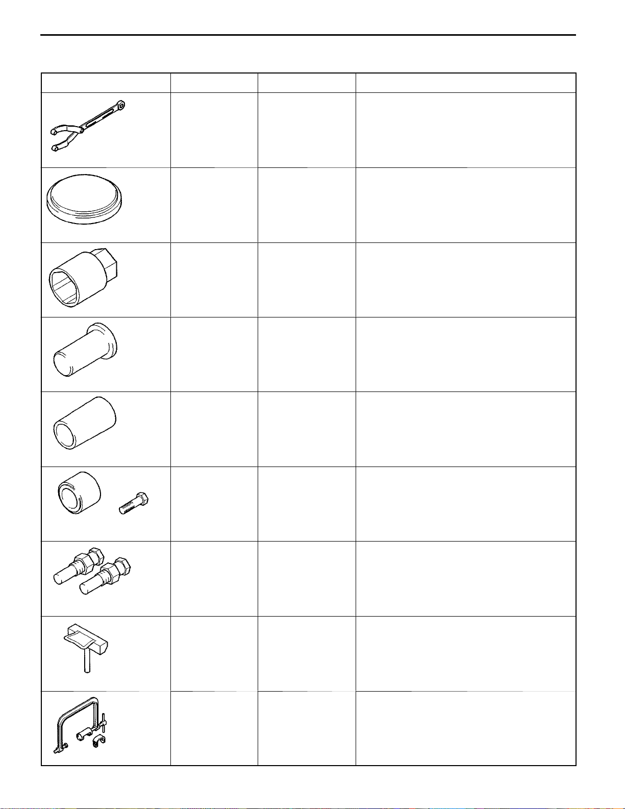
Tool Number Name Use
MB990767 End yoke holder Holding camshaft sprocket when loosening or
11A-2-1
tightening bolt (used with MD998715)
MD99801 1 Crankshaft rear oil
seal installer
MD998054 Oil pressure switch
wrench
MD998304 Crankshaft front oil
seal installer
MD998305 Crankshaft front oil
seal guide
Installation of crankshaft rear oil seal
Removal and installation of oil pressure switch
Installation of crankshaft front oil seal
Guide for installation of crankshaft front oil seal
MD998713 Camshaft oil seal
installer
MD998715 Pin (2-off) Holding camshaft sprocket when loosening or
MD998727 Oil pan remover Removal of oil pan
MD998735 Valve spring com-
pressor
Installation of camshaft oil seal
tightening bolt (used with MB990767)
Compression of valve springs
E
Nov. 1995Mitsubishi Motors Corporation
PWEE9520
Page 22
11A-2-2
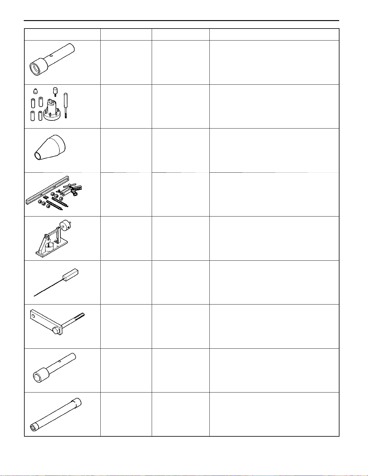
Tool UseNameNumber
4G1 ENGINE (E-W) -
Special Tools
MD998760 Valve stem seal
installer
MD998780 Piston pin setting
Installation of valve stem seals
(SOHC 12-VALVE)
Removal and press-fitting of piston pins
tool
MB991659 Guide-D Guide for removal and press-fitting of piston
pins
MD998772 Valve spring com-
Compression of valve springs
pressor
MD998440 Leak-down tester Testing of automatic lash adjusters
(DOHC)
MD998442 Air bleed wire Testing of automatic lash adjusters
(DOHC)
MD998781 Flywheel stopper Locking flywheel in fixed position
MB991671 Valve stem
installer
Press-fitting of valve stem seals
(SOHC 16-VALVE, DOHC)
MB991653 Cylinder head bolt
Removal and installation of cylinder head bolt
wrench (10)
E
E
Nov. 1995Mitsubishi Motors Corporation
Dec. 1998Mitsubishi Motors Corporation Revised
PWEE9520
PWEE9520-A
Page 23
4G1 ENGINE (E-W) -
Alternator and Ignition System
3. ALTERNATOR AND IGNITION SYSTEM
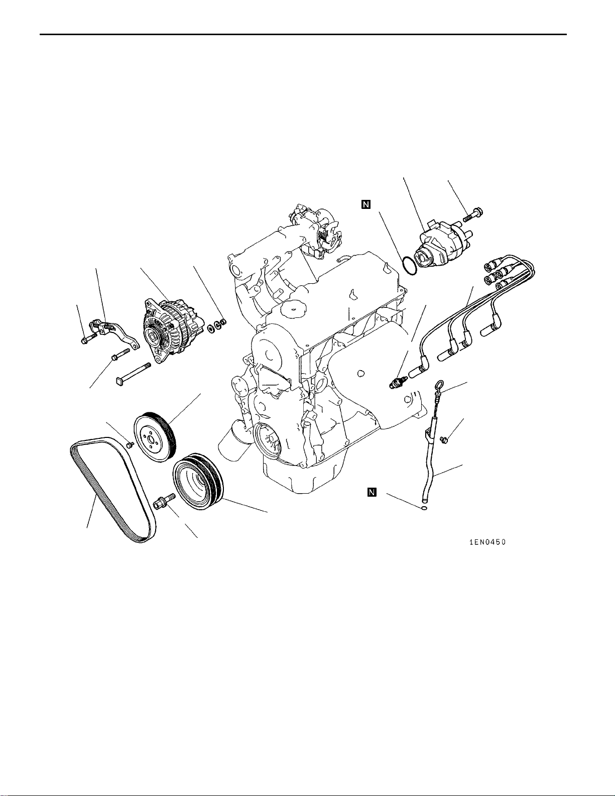
REMOVAL AND INSTALLATION <SOHC 12-VALVE>
11A-3-1
22 Nm
23 Nm
6
9Nm
12
12 Nm
13
7
44 Nm
10
25 Nm
11
1
5
23 Nm
2
4
AA""BA
E
E
8
123 Nm
Removal steps
1. Oil level gauge
2. Oil level gauge guide
3. O-ring
4. Drive belt*
5. Water pump pulley
6. Alternator brace
7. Alternator
8. Crankshaft bolt
9. Crankshaft pulley
Nov. 1995Mitsubishi Motors Corporation
Dec. 1998Mitsubishi Motors Corporation Revised
9
PWEE9520
PWEE9520-A
3
10. Spark plug cable
11. Spark plug
"AA
NOTE
*: For details of adjustment, refer to the relevant model’s
chassis workshop manual.
12. Distributor
13. O-ring
Page 24
11A-3-1a
4G1 ENGINE (E-W) -
Alternator and Ignition System
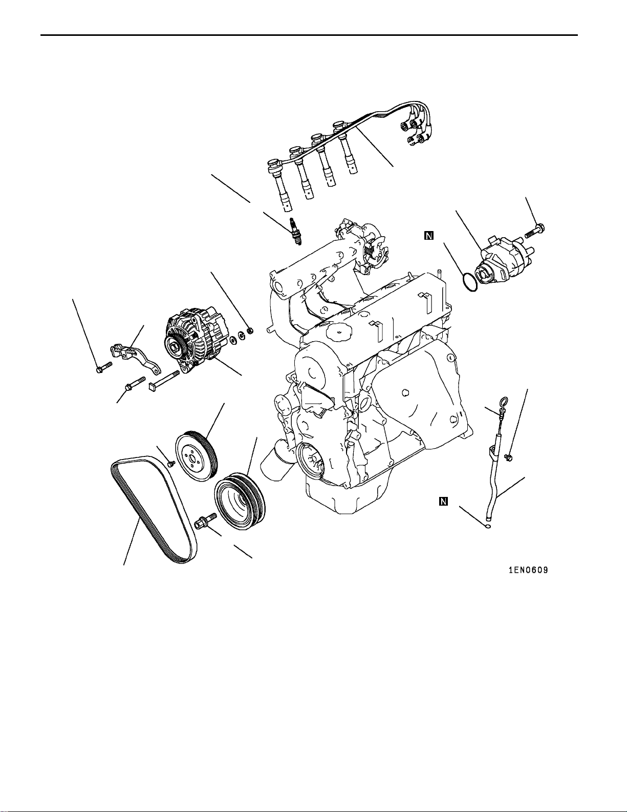
REMOVAL AND INSTALLATION <SOHC 16-VALVE-FRONT WHEEL DRIVE>
22Nm
23 Nm
6
9Nm
25 Nm
44 Nm
10
12 Nm
11
12
13
7
23 Nm
5
1
9
AA""BA
4
Removal steps
1. Oil level gauge
2. Oil level gauge guide
3. O-ring
4. Drive belt*
5. Water pump pulley
6. Alternator brace
7. Alternator
8. Crankshaft bolt
9. Crankshaft pulley
2
3
8
125 Nm
10. Spark plug cable
11. Spark plug
"AA
NOTE
*: For details of adjustment, refer to the relevant model’s
chassis workshop manual.
12. Distributor
13. O-ring
E
E
Nov. 1995Mitsubishi Motors Corporation
Dec. 1998Mitsubishi Motors Corporation Added
PWEE9520
PWEE9520-A
Page 25
4G1 ENGINE (E-W) -
Alternator and Ignition System
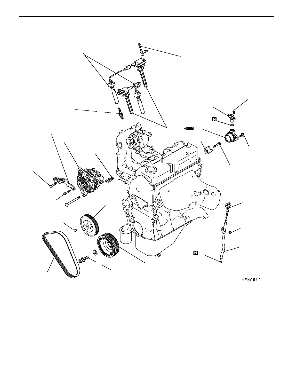
REMOVAL AND INSTALLATION <SOHC 16-VALVE-REAR WHEEL DRIVE>
10
10 Nm
25Nm
12
13
11A-3-1b
9Nm
22Nm
6
23 Nm
4
9Nm
11
7
44 Nm
5
14
15
13 Nm
21 Nm
1
23 Nm
2
3
8
125 Nm
9
AA""BA
E
E
Removal steps
1. Oil level gauge
2. Oil level gauge guide
3. O-ring
4. Drive belt*
5. Water pump pulley
6. Alternator brace
7. Alternator
8. Crankshaft bolt
9. Crankshaft pulley
Nov. 1995Mitsubishi Motors Corporation
Dec. 1998Mitsubishi Motors Corporation Added
NOTE
PWEE9520
PWEE9520-A
10. Spark plug cable
11. Ignition coil
12. Spark plug
13. Cam position sensor
"CA
*: For details of adjustment, refer to the relevant model’s
chassis workshop manual.
14. Cam position sensor support
15. Cam position sensing cylinder
Page 26
11A-3-2
4G1 ENGINE (E-W) -
Alternator and Ignition System
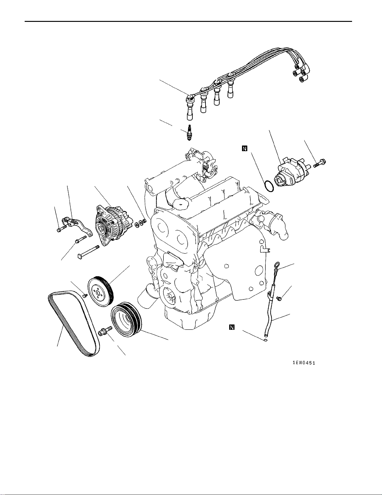
REMOVAL AND INSTALLATION <DOHC>
10
25 Nm
11
12
11 Nm
13
22Nm
23 Nm
4
6
9Nm
7
44 Nm
5
1
23 Nm
2
3
8
103 Nm
9
AA""BA
E
Removal steps
1. Oil level gauge
2. Oil level gauge guide
3. O-ring
4. Drive belt*
5. Water pump pulley
6. Alternator brace
7. Alternator
8. Crankshaft bolt
9. Crankshaft pulley
Nov. 1995Mitsubishi Motors Corporation
PWEE9520
10. Spark plug cable
11. Spark plug
"AA
NOTE
*: For details of adjustment, refer to the relevant model’s
chassis workshop manual.
12. Distributor
13. O-ring
Page 27
MD998781
Alignment mark
4G1 ENGINE (E-W) -
REMOVAL SERVICE POINT
AA"
(1) Lock the flywheel or drive plate in position using the special
INSTALLATION SERVICE POINTS
"AA
(1) Turn the crankshaft clockwise until cylinder No. 1 is at
(2) Align the alignment marks on the distributor housing and
(3) Fit the distributor onto the engine, aligning the stud bolts
Alignment mark
Alternator and Ignition System
11A-3-3
CRANKSHAFT BOLT REMOVAL
tool shown in the illustration, then loosen the crankshaft
bolts.
DISTRIBUTOR INSTALLATION
top dead center on its compression stroke.
coupling.
with the slots in the distributor mounting flange.
MD998781
"BA
CRANKSHAFT BOLT INSTALLATION
(1) Lock the flywheel or drive plate in position using the special
tool shown in the illustration, then tighten the crankshaft
bolts.
E
Nov. 1995Mitsubishi Motors Corporation
PWEE9520
Page 28

NOTES
Page 29
4G1 ENGINE (E-W) -
4. TIMING BELT
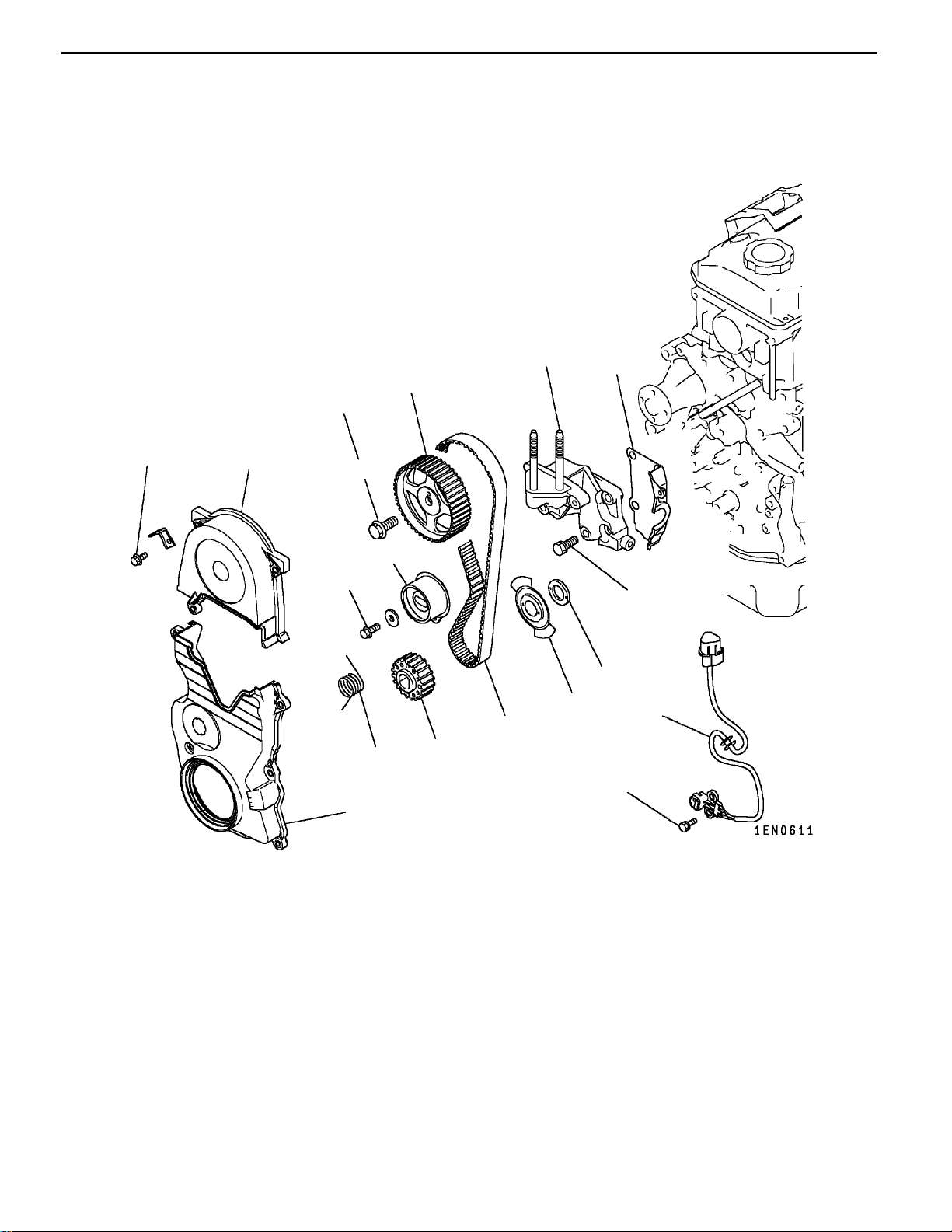
REMOVAL AND INSTALLATION <SOHC>
Timing Belt
11A-4-1
11 Nm
12
13
11
88 Nm
1
10
5
23 Nm
35 Nm
8
9
6
3
4
7
9Nm
AA""CA
"BA
"BA
E
E
E
2
Removal steps
1. Timing belt upper cover
2. Timing belt lower cover
3. Timing belt
4. Tensioner spring
5. Timing belt tensioner
6. Crankshaft angle sensor
<Rear wheel drive>
Nov. 1995Mitsubishi Motors Corporation
Dec. 1998Mitsubishi Motors Corporation RevisedPWEE9520-A
Dec. 1998Mitsubishi Motors Corporation Revised
AB""AA
PWEE9520
PWEE9520-A
7. Crankshaft sprocket
8. Spacer <Rear wheel drive>
9. Sensing blade <Rear wheel drive>
10. Camshaft sprocket bolt
11. Camshaft sprocket
12. Engine support bracket
13. Timing belt rear cover
Page 30
11A-4-2
4G1 ENGINE (E-W) -
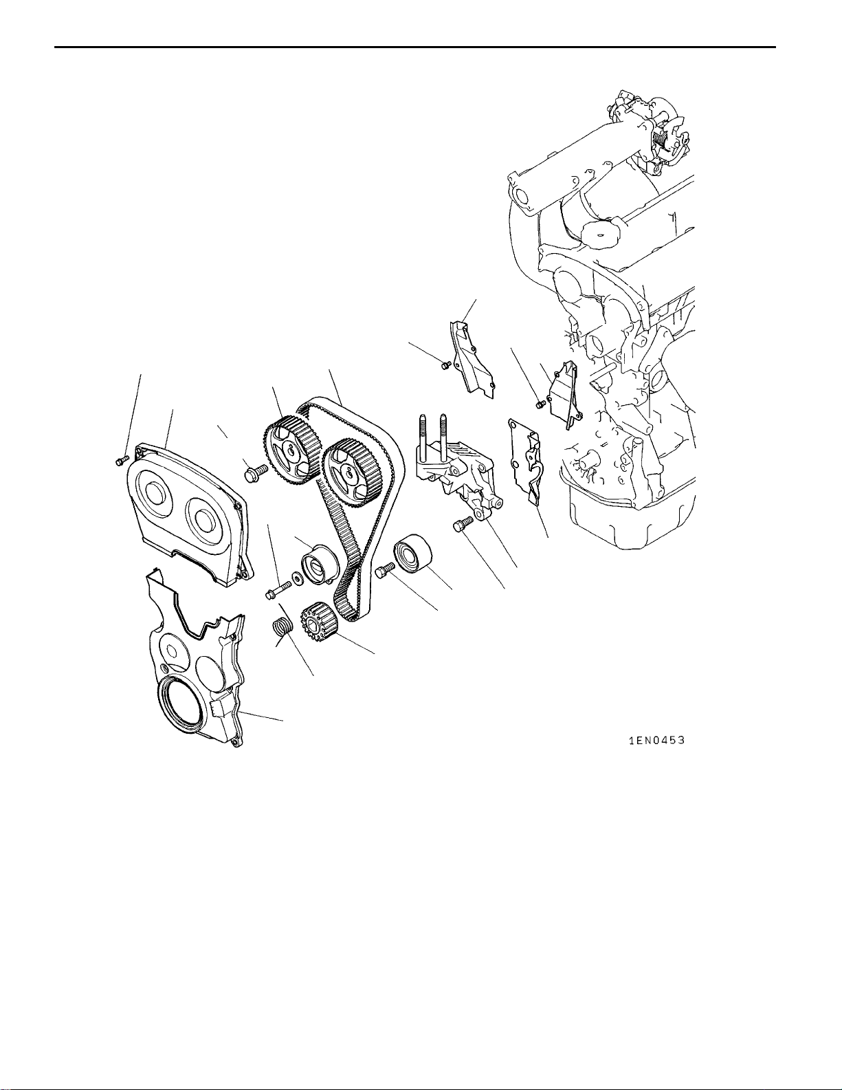
REMOVAL AND INSTALLATION <DOHC>
Timing Belt
12
11 Nm
11 Nm
3
11 Nm
13
9
1
88 Nm
8
23 Nm
5
11
10
6
35 Nm
35 Nm
7
4
2
AA""DA
AA""BA
AA""BA
E
Removal steps
1. Timing belt upper cover
2. Timing belt lower cover
3. Timing belt
4. Tensioner spring
5. Timing belt tensioner
6. Idler pulley
7. Crankshaft pulley
Nov. 1995Mitsubishi Motors Corporation
PWEE9520
AB""AA
8. Camshaft sprocket bolt
9. Camshaft sprocket
10. Engine support bracket
11. Timing belt rear cover (lower)
12. Timing belt rear cover (right)
13. Timing belt rear cover (left)
Page 31

MD998715
4G1 ENGINE (E-W) -
MB990767
Timing Belt
11A-4-3
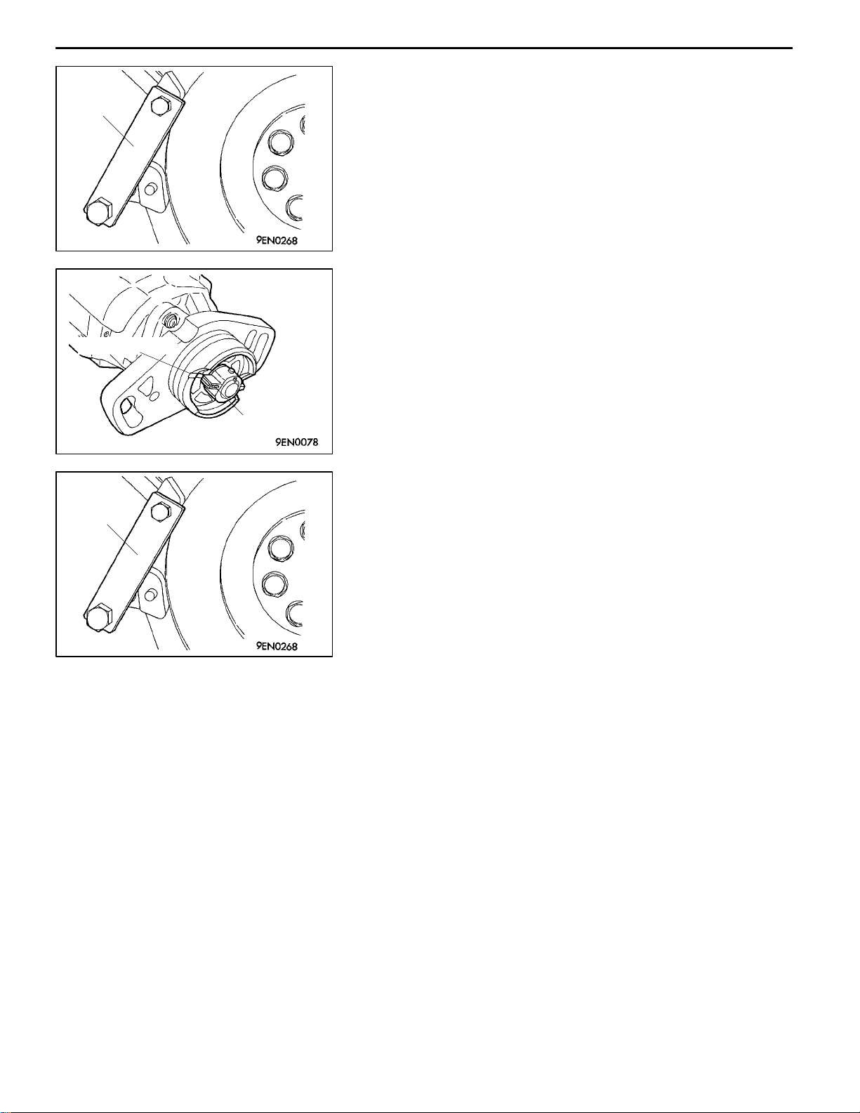
REMOVAL SERVICE POINTS
AA"
(1) Using pliers, grip t he tensioner spring projection (marked
(2) Remove the timing belt tensioner.
(3) If the timing belt is to be reused, chalk an arrow on the
AB"
(1) Using the special tools shown in the illustration, lock the
(2) Loosen the camshaft sprocket bolt.
TIMING BELT / TENSIONER SPRING / TIMING
BELT TENSIONER REMOVAL
“A” in the diagram)and remove it from the oil pump case
stopper. Then, remove the tensioner spring.
belt to indicate the direction of rotation before removing
it. This will ensure the timing belt is fitted correctly when
reused.
CAMSHAFT SPROCKET BOLT REMOVAL
camshaft sprocket in position.
Crack
Separation
Cracked tooth base
Rounded edge
Crack
Cracked side
INSPECTION
1. TIMING BELT
Check the timing belt closely. Replace the belt with a new
one if any of the following defects is evident:
(1) Hardened backing rubber (the backing rubber is glossy,
non-elastic, and so hard that scratching with fingernails
leaves no mark)
(2) Surface cracks in the backing rubber
(3) Splits in the canvas and/or separation of the canvas a n d
rubber
(4) Cracks at the bases of teeth
(5) Cracks in the side of the belt
(6) Abnormal wear on the belt’s sides
NOTE
The sides of the belt are normal if they are sharp as
if cut by a knife.
Abnormal wear
(exposed core wire)
E
Nov. 1995Mitsubishi Motors Corporation
PWEE9520
Page 32

11A-4-4
Canvas worn exposing
rubber
Missing tooth
4G1 ENGINE (E-W) -
(7) Abnormal wear on teeth
Initial stage:
Canvas worn (fluffy canvas fibers, rubbery texture gone,
white discoloration, canvas texture indistinct)
Final stage:
Canvas worn, exposing rubber (tooth width reduced)
(8) Missing teeth
2. TENSIONER PULLEY AND IDLER PULLEY
(1) Check that the pulleys turn smoothly without play and
are not abnormally noisy. Replace either or both of the
pulleys if necessary.
Timing Belt
MD998715
MB990767
Timing belt
tensioner
INSTALLATION SERVICE POINTS
"AA
(1) Using the special tools shown in the illustration, lock the
(2) Tighten the camshaft sprocket bolt to the specified torque.
"BA
(1) Lock the timing belt tensioner in the illustrated position.
(2) Fit one of the tensioner spring projections over the hooked
CAMSHAFT SPROCKET BOLT INSTALLATION
camshaft sprocket in position.
TIMING BELT TENSIONER / TENSIONER SPRING
INSTALLATION
portion of the timing belt tensioner and fit the tensioner
onto the oil pump case.
E
Nov. 1995Mitsubishi Motors Corporation
PWEE9520
Page 33

4G1 ENGINE (E-W) -
(3) Grip the other tensioner spring projection and fit it onto
the oil pump case lug as shown in the illustration.
(4) Move the timing belt tensioner in the direction shown
and temporarily tighten the bolt.
Timing Belt
11A-4-5
"CA
TIMING BELT INSTALLATION
(1) Align the camshaft timing mark with the timing mark on
the cylinder head.
(2) Align the crankshaft timing mark with the timing mark
on the front case.
(3) Keeping the tension side of the timing belt tight, fit the
timing belt onto the crankshaft sprocket, camshaft
sprocket, and tensioner pulley in that order.
(4) Loosen the tensioner pulley mounting bolts by 1/4 to
1/2 of a turn an d allow the tensioner spring to apply tension
to the timing belt.
(5) Turn the crankshaft twice in the normal rotating direction
(clockwise) and check that the timing marks are correctly
aligned.
Caution
This procedure utilizes the camshaft’s driving torque
to apply tension evenly to the timing belt. Be sure
to turn the crankshaft as described above. Do not
turn the crankshaft in reverse.
(6) Tighten the tensioner pulley mounting bolts.
E
Nov. 1995Mitsubishi Motors Corporation
PWEE9520
Page 34

11A-4-6
4G1 ENGINE (E-W) -
Timing Belt
"DA
TIMING BELT INSTALLATION
(1) Place the camshaft sprocket timing marks at the positions
shown.
NOTE
After aligning the sprocket timing marks, let go of the
sprockets. The exhaust camshaft sprocket will rotate by
one tooth in the direction shown and remain stable in
this position.
(2) Align the crankshaft timing mark with the timing mark
on the front case.
(3) Turn the exhaust camshaft sprocket in the direction shown
and fit the timing belt with the timing marks aligned.
(4) Use a bulldog clip to prevent the timing belt teeth from
jumping.
(5) Fit the timing belt onto the idler pulley, crankshaft sprocket,
and tensioner pulley in that order.
NOTE
When fitting the belt, keep the camshaft sprocket timing
marks correctly aligned a nd keep the tension side of the
belt tight.
1
(6) Loosen the tensioner pulley mounting bolts by
/4to1/
2
of a turn and allow t he tensioner spring to apply tension
to the timing belt.
(7) Remove the bulldog clip.
(8) Turn the crankshaft twice in the normal rotating direction
(clockwise) and check that the timing marks are correctly
aligned.
Caution
This procedure utilizes the camshaft’s driving torque
to apply tension evenly to the timing belt. Be sure
to turn the crankshaft as described above. Do not
turn the crankshaft in reverse.
(9) Tighten the tensioner pulley mounting bolts.
E
Nov. 1995Mitsubishi Motors Corporation
PWEE9520
Page 35

4G1 ENGINE (E-W) -
Fuel and Emission Control Systems
5. FUEL AND EMISSION CONTROL SYSTEMS
REMOVAL AND INSTALLATION <SOHC-CARBURETOR>
17 Nm
8
9
11A-5-1
7
11 Nm
22 Nm
3
10
21 Nm
11
2
4
12
5
6
1
Removal steps
1. Breather tube
2. Fuel hose
3. Fuel pump
4. Gasket
5. Insulator
6. Gasket
E
Nov. 1995Mitsubishi Motors Corporation
PWEE9520
7. Carburetor
8. Upper gasket
9. Spacer
10. Lower gasket
11. EGR valve (vehicles with automatic
transmission for GCC only)
12. Gasket
Page 36

11A-5-2
4G1 ENGINE (E-W) -
Fuel and Emission Control Systems
REMOVAL AND INSTALLATION <SOHC-MPI>
11 Nm
9Nm
3
11
18 Nm
1
6
9
5
4
10
8
2
21 Nm
7
12
13
"BA
Removal steps
1. Throttle body assembly
2. Gasket
3. Fuel return pipe
4. Fuel pressure regulator
5. O-ring
6. Insulator
7. Insulator
"AA
15
8. Injector
9. O-ring
10. Grommet
11. Delivery pipe
12. EGR valve
13. Gasket
14. Air temperature sensor
15. Gasket
14
18 Nm
E
Nov. 1995Mitsubishi Motors Corporation
PWEE9520
Page 37

4G1 ENGINE (E-W) -
Fuel and Emission Control Systems
REMOVAL AND INSTALLATION <SOHC-REAR WHEEL DRIVE>
9Nm
11A-5-2a
4
9Nm
3
11 Nm
18 Nm
11
2
5
10
9
6
1
21 Nm
8
7
12
13
Removal steps
1. Throttle body assembly
2. Gasket
3. Fuel return pipe
"BA
E
E
4. Fuel pressure regulator
5. O-ring
6. Insulator
7. Insulator
Nov. 1995Mitsubishi Motors Corporation
Dec. 1998Mitsubishi Motors Corporation Added
PWEE9520
PWEE9520-A
"AA
8. Injector
9. O-ring
10. Grommet
11. Delivery pipe
12. EGR valve
13. Gasket
Page 38

11A-5-2b
4G1 ENGINE (E-W) -
Fuel and Emission Control Systems
Intentionally blank
E
E
Nov. 1995Mitsubishi Motors Corporation
Dec. 1998Mitsubishi Motors Corporation Added
PWEE9520
PWEE9520-A
Page 39

4G1 ENGINE (E-W) -
Fuel and Emission Control Systems
REMOVAL AND INSTALLATION <DOHC>
11 Nm
11A-5-3
9Nm
3
11
18 Nm
1
6
2
9
5
4
10
8
7
Removal steps
1. Throttle body assembly
2. Gasket
3. Fuel return pipe
"BA
E
4. Fuel pressure regulator
5. O-ring
6. Insulator
Nov. 1995Mitsubishi Motors Corporation
PWEE9520
"AA
7. Insulator
8. Injector
9. O-ring
10. Grommet
11. Delivery pipe
Page 40

11A-5-4
4G1 ENGINE (E-W) -
Fuel and Emission Control Systems
INSTALLATION SERVICE POINTS
"AA
(1) Fit a new O-ring and grommet onto the injector.
(2) Apply spindle oil or gasoline to the injector O-ring.
(3) Fit the injector onto the delivery pipe, turning it to the
(4) Check that the injector rotates smoothly.
INJECTOR INSTALLATION
left and right as it goes in.
Caution
If the injector does not rotate smoothly, its O-ring
may be binding. If this occurs, remove the injector
from the delivery pipe, check the O-ring, and re-insert
the injector.
"BA
FUEL PRESSURE REGULATOR INSTALLATION
(1) Apply a little new engine oil to the O-ring, then insert
the fuel pressure regulator into the delivery pipe, taking
care not to damage the O-ring.
Caution
Ensure that no engine oil enters the delivery pipe.
(2) Check that the fuel pressure regulator rotates smoothly.
If it does not rotate smoothly, the O-ring may be binding.
If this occurs, remove the fuel pressure regulator, check
the O-ring for damage, then re-insert the regulator into
the delivery pipe.
E
Nov. 1995Mitsubishi Motors Corporation
PWEE9520
Page 41

4G1 ENGINE (E-W) -
Water Pump and Water Hose
6. WATER PUMP AND WATER HOSE
REMOVAL AND INSTALLATION <SOHC-CARBURETOR>
11A-6-1
3
12 Nm
1
2
27 Nm
4
27 Nm
11 Nm
22 Nm
12
5
11
6
8
7
9
23 Nm
10
14
13
"FA
"FA
"DA
13 Nm
Removal steps
1. Water hose
2. Water hose
3. Water hose
4. Thermo valve (engines with EGR)
5. Thermo valve
6. Water temperature gauge unit
7. Water inlet fitting
"CA
"BA
"BA
"BA
"AA
8. Thermostat
9. Thermostat case
10. Gasket
11. Water inlet pipe
12. O-ring
13. O-ring
14. Water pump
E
Nov. 1995Mitsubishi Motors Corporation
PWEE9520
Page 42

11A-6-2
4G1 ENGINE (E-W) -
Water Pump and Water Hose
REMOVAL AND INSTALLATION <SOHC-MPI>
12 Nm
10
12
11
2
29 Nm
7
6
22 Nm
3
11 Nm
4
8
9
5
23 Nm
1
13 Nm
Removal steps
1. Water hose
2. Water hose
"EA
"DA
"CA
E
3. Water temperature sensor
4. Water temperature gauge unit
5. Water inlet fitting
6. Thermostat
7. Thermostat case
Nov. 1995Mitsubishi Motors Corporation
PWEE9520
"BA
"BA
"BA
"AA
8. Gasket
9. Water inlet pipe
10. O-ring
11. O-ring
12. Water pump
Page 43

4G1 ENGINE (E-W) -
Water Pump and Water Hose
11A-6-2a
REMOVAL AND INSTALLATION <SOHC 16-VALVE-MPI-FRONT WHEEL DRIVE>
2
12 Nm
1
9
12 Nm
10
13 Nm
12
11
29 Nm
23 Nm
3
8
7
4
6
5
11 Nm
22 Nm
Removal steps
1. Water hose
2. Water hose
"EA
"DA
"CA
E
E
3. Water temperature sensor
4. Water temperature gauge unit
5. Water inlet fitting
6. Thermostat
7. Thermostat case
Nov. 1995Mitsubishi Motors Corporation
Dec. 1998Mitsubishi Motors Corporation Added
PWEE9520
PWEE9520-A
"BA
"BA
"BA
"AA
8. Gasket
9. Water inlet pipe
10. O-ring
11. O-ring
12. Water pump
Page 44

11A-6-2b
4G1 ENGINE (E-W) -
Water Pump and Water Hose
REMOVAL AND INSTALLATION <SOHC 16-VALVE-MPI-REAR WHEEL DRIVE>
25 Nm
29 Nm
11 Nm
1
12 Nm
11
2
12 Nm
23 Nm
5
6
10
7
9
3
8
4
12
23 Nm
13 Nm
Removal steps
1. Water hose
2. Water hose
"EA
"DA
E
E
3. Water temperature sensor
4. Water temperature gauge unit
5. Water outlet fitting
6. Gasket
Nov. 1995Mitsubishi Motors Corporation
Dec. 1998Mitsubishi Motors Corporation Added
PWEE9520
PWEE9520-A
"CA
"BA
"BA
"AA
7. Thermostat
8. Fitting
9. Gasket
10. Water inlet pipe
11. O-ring
12. Water pump
Page 45

4G1 ENGINE (E-W) -
Water Pump and Water Hose
REMOVAL AND INSTALLATION <DOHC>
12 Nm
11A-6-3
12 Nm
10
2
11
1
29 Nm
8
7
3
22 Nm
9
6
12
23 Nm
4
5
11 Nm
13 Nm
Removal steps
1. Water hose
2. Water hose
"EA
"DA
"CA
E
3. Water temperature sensor
4. Water temperature gauge unit
5. Water inlet fitting
6. Thermostat
7. Thermostat case
Nov. 1995Mitsubishi Motors Corporation
PWEE9520
"BA
"BA
"BA
"AA
8. Gasket
9. Water inlet pipe
10. O-ring
11. O-ring
12. Water pump
Page 46

11A-6-4
4G1 ENGINE (E-W) -
INSTALLATION SERVICE POINTS
"AA
(1) Apply a 3 mm bead of form-in-place gasket (FIPG) to
Water Pump and Water Hose
WATER PUMP INSTALLATION
the mounting surface.
Specified sealant:
Mitsubishi Genuine Part No. MD970389 or
equivalent.
"BA
O-RING / WATER PIPE INSTALLATION
(1) Replace the water inlet pipe O-rings with new ones, then
apply water to the O-rings so that they can be inserted
easily into the water pump and thermostat case.
Caution
1. Donotapply engine oil or any otheroilysubstance
to the O-rings.
2. Secure the water pipe after the thermostat case
has been installed.
"CA
THERMOSTAT INSTALLATION
(1) Fit the thermostat such that its jiggle valve is at the top.
"DA
WATER TEMPERATURE GAUGE UNIT
INSTALLATION
(1) If the water temperature gauge unit is to be reused, apply
the specified sealant to its thread.
Specified sealant:
3M ATD Part No. 8660 or equivalent.
"EA
WATER TEMPERATURE SENSOR INSTALLATION
(1) If the water temperature sensor is to be reused, apply
the specified sealant to its thread.
Specified sealant:
3M Nut Locking Part No. 4171 or equivalent.
E
Nov. 1995Mitsubishi Motors Corporation
PWEE9520
Page 47

4G1 ENGINE (E-W) -
Water Pump and Water Hose
11A-6-5
"FA
THERMO VALVE INSTALLATION
(1) If the thermo valve is to be reused, apply the specified
sealant to its thread.
Specified sealant:
Mitsubishi Genuine Part No. MD970389 or
equivalent.
E
Nov. 1995Mitsubishi Motors Corporation
PWEE9520
Page 48

NOTES
Page 49

4G1 ENGINE (E-W) -
Intake and Exhaust Manifolds
7. INTAKE AND EXHAUST MANIFOLDS
REMOVAL AND INSTALLATION <SOHC-CARBURETOR>
1
3
4
11A-7-1
8
17 Nm
30 Nm
7
5
2
17 Nm
29 Nm
6
Removal steps
1. Engine hanger
2. Intake manifold stay
3. Intake manifold
4. Intake manifold gasket
E
Nov. 1995Mitsubishi Motors Corporation
PWEE9520
5. Exhaust manifold cover
6. Engine hanger
7. Exhaust manifold
8. Exhaust manifold gasket
Page 50

11A-7-2
4G1 ENGINE (E-W) -
Intake and Exhaust Manifolds
REMOVAL AND INSTALLATION <SOHC-MPI>
1
17 Nm
17 Nm
21 Nm
2
3
44 Nm
4
5
9
8
17 Nm
7
29 Nm
6
Removal steps
1. Engine hanger
2. Intake manifold stay
3. Intake manifold
4. Intake manifold gasket
5. Oxygen sensor (vehicles for Hong
Kong only)
E
Nov. 1995Mitsubishi Motors Corporation
PWEE9520
6. Exhaust manifold cover
7. Engine hanger
8. Exhaust manifold
9. Exhaust manifold gasket
Page 51

4G1 ENGINE (E-W) -
Intake and Exhaust Manifolds
11A-7-2a
REMOVAL AND INSTALLATION <SOHC 16-VALVE-MPI-REAR WHEEL DRIVE>
17 Nm
17 Nm
5Nm
1
21 Nm
6
9Nm
7
2
4
5
29 Nm
11
9
10
3
19 Nm
Removal steps
1. Boost sensor
2. Engine hanger
3. Intake manifold stay
4. Intake manifold
5. Intake manifold gasket
6. Solenoid valve assembly <Without
catalytic converter>
17 Nm
8
29 Nm
7. Solenoid valve assembly <With catalytic converter>
8. Engine hanger
9. Exhaust manifold cover
10. Exhaust manifold
11. Exhaust manifold gasket
E
E
Nov. 1995Mitsubishi Motors Corporation
Dec. 1998Mitsubishi Motors Corporation Added
PWEE9520
PWEE9520-A
Page 52

11A-7-2b
4G1 ENGINE (E-W) -
Intake and Exhaust Manifolds
REMOVAL AND INSTALLATION <SOHC-CARBURETOR FOR CENTRAL AMERICA>
5
17 Nm
11
8
1
3
4
2
13 Nm
10
11 Nm
54 Nm
9
7
8
12
6
83 Nm
29 Nm
30 Nm
17 Nm
Removal steps
1. Engine hanger
2. Intake manifold stay
3. Intake manifold
4. Intake manifold gasket
5. Air hose
6. Exhaust manifold cover
E
E
Nov. 1995Mitsubishi Motors Corporation
July 1999Mitsubishi Motors Corporation Revised
PWEE9520
PWEE9520-B
"AA
"AA
7. Air pipe
8. Reed valve and bracket
9. Reed valve
10. Reed valve bracket “A”
11. Reed valve bracket “B”
12. Exhaust manifold
Page 53

4G1 ENGINE (E-W) -
Intake and Exhaust Manifolds
REMOVAL AND INSTALLATION <DOHC>
1
3
4
17 Nm
11A-7-3
8
9
17 Nm
21 Nm
2
Removal steps
1. Engine hanger
2. Intake manifold stay
3. Intake manifold
4. Intake manifold gasket
5. Oxygen sensor
6
17 Nm
29 Nm
44 Nm
5
29 Nm
7
6. Exhaust manifold cover
7. Engine hanger
8. Exhaust manifold
9. Exhaust manifold gasket
E
Nov. 1995Mitsubishi Motors Corporation
PWEE9520
Page 54

11A-7-4
4G1 ENGINE (E-W) -
Intake and Exhaust Manifolds
Reed valve and bracket
Pipe nut (reed valve side)
Air pipe
Reed valve
bracket “B”
Pipe nut (exhaust
manifold side)
Pipe clamp bolt
INSTALLATION SERVICE POINTS
"AA
(1) Insert the lower end of the air pipe into the exhaust
(2) Fit the upper end of the air pipe to the reed valve a n d
(3) Attach the reed valve and bracket assembly to the reed
(4) Tighten the nutson both ends of the air pipe to thespecified
(5) Tighten the reed valve and bracket mounting bolts to
(6) Tighten the pipe clamp bolt.
REED VALVE, BRACKET AND AIR PIPE
INSTALLATION
manifold, then tighten the pipe nut temporarily.
bracket assembly, then tighten the pipe nut temporarily.
valve bracket “B” and tighten the mounting bolts
temporarily.
torque.
Caution
The tightening torque of the reed valve side nut and
that of the exhaust manifold side nut are different
from each other.
Be sure to tighten each nut correctly to the specified
torque.
the specified torque.
E
E
Nov. 1995Mitsubishi Motors Corporation
July 1999Mitsubishi Motors Corporation Added
PWEE9520
PWEE9520-B
Page 55

NOTES
Page 56

4G1 ENGINE (E-W) -
Rocker Arms and Camshafts
8. ROCKER ARMS AND CAMSHAFTS
REMOVAL AND INSTALLATION <SOHC 12-VALVE>
1
3
4
2
5
7
6
4Nm
14
11A-8-1
9
31 Nm
10
11
12
13
19
20
21
15 Nm
18
17
16
22
15
Apply engine oil to all
moving parts before
8
installation.
Removal steps
1. Breather hose
2. P.C.V. hose
3. P.C.V. valve
4. P.C.V. valve gasket
5. Oil filler cap
6. Rocker cover
7. Rocker cover gasket
"FA
"EA
"EA
E
E
8. Camshaft oil seal
9. Rocker arm and shaft assembly
10. Rocker arm and shaft assembly
11. Rocker arm A
Nov. 1995Mitsubishi Motors Corporation
Dec. 1998Mitsubishi Motors Corporation Revised
PWEE9520
PWEE9520-A
"CA
12. Rocker arm spring
13. Rocker arm B
14. Rocker arm shaft
15. Rocker arm C
16. Wave washer
17. Spacer
18. Rocker arm D
19. Rocker arm shaft
20. Adjusting screw
21. Nut
22. Camshaft
Page 57

11A-8-1a
4G1 ENGINE (E-W) -
Rocker Arms and Camshafts
REMOVAL AND INSTALLATION <SOHC 16-VALVE>
4
1
2
5
35 Nm
31 Nm
3
6
14
10
11
7
18
13
12
19
20
9Nm
15
16
9Nm
8
9
17
21
Apply engine oil to all
moving parts before
installation.
Removal steps
1. Breather hose
2. P.C.V. hose
3. Oil filler cap
4. P.C.V. valve
5. P.C.V. valve gasket
6. Rocker cover
7. Rocker cover gasket
8. Oil seal
"FA
"EA
"EA
E
E
9. Oil seal
10. Rocker arms and rocker arm shaft
IN
11. Rocker arms and rocker arm shaft
EX
Nov. 1995Mitsubishi Motors Corporation
Dec. 1998Mitsubishi Motors Corporation Added
PWEE9520
PWEE9520-A
"DA
"CA
"DA
"CA
12. Rocker arm B
13. Rocker arm A
14. Rocker arm shaft
15. Adjusting screw
16. Nut
17. Rocker arm C
18. Rocker arm shaft
19. Adjusting screw
20. Nut
21. Camshaft
Page 58

4G1 ENGINE (E-W) -
Rocker Arms and Camshafts
11A-8-1b
Intentionally blank
E
E
Nov. 1995Mitsubishi Motors Corporation
Dec. 1998Mitsubishi Motors Corporation Added
PWEE9520
PWEE9520-A
Page 59

11A-8-2
4G1 ENGINE (E-W) -
Rocker Arms and Camshafts
REMOVAL AND INSTALLATION <DOHC>
Apply engine oil to all
moving parts before
installation.
2
1
10
4Nm
7
11 Nm
11
12
3
5
4
6
9
24 Nm
8
13
14
15
Removal steps
1. Breather hose
2. P.C.V. hose
3. P.C.V. valve
4. P.C.V. valve gasket
5. Oil filler cap
"HA
E
E
6. Rocker cover
7. Rocker cover gasket A
8. Rocker cover gasket B
Nov. 1995Mitsubishi Motors Corporation
Dec. 1998Mitsubishi Motors Corporation Revised
PWEE9520
PWEE9520-A
"GA
"FA
"BA
"AA
"AA
9. Semi-circular packing
10. Camshaft oil seal
11. Bearing cap
12. Camshaft
13. Camshaft
14. Roller rocker arm
15. Lash adjuster
Page 60

4G1 ENGINE (E-W) -
INSPECTION
1. CAMSHAFT
(1) Measure the cam heights and replace the camshaft if
Rocker Arms and Camshafts
any height exceeds the specified limit.
11A-8-3
Intake SOHC
12-VALVE
SOHC
16-VALVE
DOHC 34.67 34.17
Exhaust SOHC
12-VALVE
SOHC
16-VALVE
DOHC 34.26 33.76
Standard value
mm
38.78 38.28
36.99 36.49
39.10 38.60
36.85 36.35
Limit mm
2. LASH ADJUSTERS
Caution
1. The lash adjusters are precision-engineered
mechanisms. Do not allow them to become
contaminated by dirt or other foreign substances.
2. Do not attempt to disassemble the lash adjusters.
3. Use only fresh diesel fuel to clean the lash
adjusters.
(1) Prepare three containers and approximately five liters
To clean
outside
To clean
inside
To fill
diesel fuel
of diesel fuel. Into each container, pour enough diesel
fuel to completely cover a lash adjuster when it is standing
upright. Then, perform the following steps with each lash
adjuster.
A
B
C
(2) Place the lash adjuster in container A and clean its outside
surface.
NOTE
Use a nylon brush if deposits are hard to remove.
Diesel fuel
E
E
Nov. 1995Mitsubishi Motors Corporation
Dec. 1998Mitsubishi Motors Corporation Revised
PWEE9520
PWEE9520-A
Page 61

11A-8-4
MD998442
4G1 ENGINE (E-W) -
(3) While gently pushing down the internal steel ball using
Diesel fuel
Rocker Arms and Camshafts
special tool MD998442, move the plunger through 5 to
10 strokes until it slides smoothly. In addition to eliminating
stiffness in the plunger, this operation will remove dirty
oil.
Caution
The steel ball spring is extremely weak, so the lash
adjuster’s functionality may be lost if the air bleed
wire is pushed in hard.
NOTE
If the plunger remains stiff or the mechanism appears
otherwise abnormal, replace the lash adjuster.
Diesel fuel
MD998442
MD998442
Diesel fuel
MD998442
(4) Removal the lash adjuster from the container. Then, push
down thesteel ball gently and push the plunger to eliminate
diesel fuel from the pressure chamber.
Caution
Makesuretheoilholeinthesideof thebody ispointing
towardcontainerA. Donotpointtheoil hole atyourself
or other people.
(5) Place the lash adjuster in container B. Then, gently push
down the internal steel ball using special tool MD998442
and move the plunger through 5 to 10 strokes until it
slides smoothly. This operation will clean the lash
adjuster’s pressure chamber.
Caution
The steel ball spring is extremely weak, so the lash
adjuster’s functionality may be lost if the air bleed
wire is pushed in hard.
(6) Remove the lash adjuster from the container. Then, push
down thesteel ball gently and push the plunger to eliminate
diesel fuel from the pressure chamber.
Caution
Makesuretheoilholeinthesideof thebody ispointing
towardcontainerB. Donotpointtheoil hole atyourself
or other people.
Diesel fuel
E
E
Nov. 1995Mitsubishi Motors Corporation
Dec. 1998Mitsubishi Motors Corporation Revised
PWEE9520
PWEE9520-A
Page 62

4G1 ENGINE (E-W) -
(7) Place the lash adjuster in container C. Then, gently push
Rocker Arms and Camshafts
11A-8-5
down the internal steel ball using special tool MD998442.
Caution
Do not use container C for cleaning. If cleaning is
performed in container C, foreign matter could enter
the pressure chamber when chamber is filled with
diesel fuel.
MD998442
MD998442
Diesel fuel
(8) Stand the lash adjuster with its plunger at the top, then
push the plunger downward firmly until it moves through
its greatest possible stroke. Return the plunger slowly,
then release the steel ball and allow the pressure chamber
to fill with diesel fuel.
Diesel fuel
(9) Remove the lash adjuster from the container, then stand
the lash adjuster with its plunger at the top. Push the
plunger firmly and check that it does not move. Also,
check that the lash adjuster’s height matches that of a
new lash adjuster.
NOTE
If lash adjuster contracts, perform the operations (7)
through (9) again to fill it with diesel fuel completely.
Replace the lash adjuster if it still contracts after performing
these steps.
MD998440
E
E
Lash
adjuster
Division = 1 mm
Lash adjuster
Nut
Nov. 1995Mitsubishi Motors Corporation
Dec. 1998Mitsubishi Motors Corporation Revised
(10)Set the lash adjuster on the special tool MD998440 (leak
down tester).
(11)Remove the bolt from the tester, then adjust the height
as illustrated.
(12)After the plunger has moved downward slightly (0.2 to
0.5 mm), measure the time taken for it to move downward
by a further 1 mm.
Standard value:
3 - 20 second/1 mm [with diesel fuel at 15 - 20_C
(59 - 68_F)]
PWEE9520
PWEE9520-A
Page 63

11A-8-6
MD998442
4G1 ENGINE (E-W) -
(13)Place the lash adjuster in container C again, then gently
(14)Stand the lash adjuster with its plunger at the top, then
Diesel fuel
Rocker Arms and Camshafts
NOTE
Replace the lash adjuster if the time measurement is
out of specification.
push down the internal steel ball using special tool
MD998442.
push the plunger downward firmly until it moves through
its greatest possible stroke. Return the plunger slowly,
then release the steel ball and allow the pressure chamber
to fill with diesel fuel.
(15)Remove the lash adjuster from the container, then stand
the lash adjuster with its plunger at the top. Push the
plunger firmly and check that it does not move. Also,
check the lash adjuster’s height matches that of a new
lash adjuster.
NOTE
If lash adjuster contracts, perform the operations (13)
through (15) again to fill it with diesel fuel completely.
Replace the lash adjuster if it still contracts after performing
these steps.
(16)Stand the lash adjuster upright to prevent diesel fuel from
spilling out. Do not allow the lash adjuster to become
contaminated by dirt or other foreign matter. Fit the lash
adjuster onto the engine as soon as possible.
INSTALLATION SERVICE POINTS
"AA
Slit
E
E
Nov. 1995Mitsubishi Motors Corporation
Dec. 1998Mitsubishi Motors Corporation Revised
(1) Apply engine oil to the camshaft journals a nd cams before
CAMSHAFT INSTALLATION
installation. Ensure that the intake-side and exhaust-side
camshafts are not reversed.
NOTE
There is a 4 mm-wide slot in the rear end of the
exhaust-side camshaft.
PWEE9520
PWEE9520-A
Page 64

4G1 ENGINE (E-W) -
Rocker Arms and Camshafts
11A-8-7
"BA
BEARING CAP INSTALLATION
(1) Position the camshaft dowel pins as shown.
NOTE
With the camshaft dowel pins in this position, the camshaft
notches for tightening cylinder head bolt are correctly
positioned.
(2) Bearing caps Nos. 2 to 5 are the same shape. Be sure
to install them in order of their cap numbers and check
the identification marks to ensure that the intake and
exhaust sides are not reversed.
Identification marks:
I: Intake
E: Exhaust
(3) Apply the specified sealant to the surfaces that are to
mate with the cylinder head. Then, tighten the bearing
cap bolts - for the middle caps first, then for the outer
caps, and soon. Tighten the bolts a little at a time such
that each bolt is tightened to the specified torque in the
final sequence.
Specified sealant:
3M ATD Part No. 8660 or equivalent
(4) Check that the rocker arms are installed correctly.
Chamfer
E
E
Oil holes
1 mm or less
"CA
(1) Install provisionally the screw to the rocker arm. Insert
ADJUSTING SCREW INSTALLATION
it so that the end of the screw is flush with the edge
of the rocker arm or projects slightly (1 mm or less).
"DA
ROCKER ARM SHAFT INSTALLATION
(1) Place the end with the larger chamfered side toward the
flywheel side. <SOHC 12-VALVE>
Place the end with the larger chamfered side toward the
timing belt side. <SOHC 16-VALVE>
NOTE
The rocker arm shaft for intake valves have eight oil holes.
(2) Place the section of the shaft with the oil holes toward
the cylinder head.
Nov. 1995Mitsubishi Motors Corporation
Dec. 1998Mitsubishi Motors Corporation Added
PWEE9520
PWEE9520-A
Page 65

11A-8-8
4G1 ENGINE (E-W) -
Rocker Arms and Camshafts
SOHC 12-VALVE
Timing belt side
Identification mark
SOHC 16-VALVE
Timing belt side
Identification
mark
SOHC
MD998713
"EA
ROCKER ARM / ROCKER SHAFT ASSEMBLY
INSTALLATION
(1) Assemble the rocker arms and rocker shaft, paying
attention to the identification marks. Then mount the
assembly on the cylinder head.
"FA
CAMSHAFT OIL SEAL INSTALLATION
DOHC
E
E
MD998713
Sealant
"GA
(1) Apply the specified sealant to the area shown.
SEMI-CIRCULAR PACKING INSTALLATION
Specified sealant:
3M ATD Part No. 8660 or equivalent
DEN0053
Nov. 1995Mitsubishi Motors Corporation
Dec. 1998Mitsubishi Motors Corporation Added
PWEE9520
PWEE9520-A
Page 66

4G1 ENGINE (E-W) -
Rocker Arms and Camshafts
11A-8-9
Timing belt side
"HA
ROCKER COVER INSTALLATION
(1) Apply the specified sealant to the area shown, then fit
the rocker cover.
Specified sealant:
3M ATD part No. 8660 or equivalent
VALVE CLEARANCE ADJUSTMENT
<SOHC 12-VALVE>
(1) Position the No. 1 cylinder at top dead center on the
compression stroke.
(2) Adjust the valve clearance at the points shown in the
illustration.
(3) Loosen the adjusting screw locknut.
(4) Using a feeler gauge, adjust the valve clearance by turning
the adjusting screw.
Timing belt side
Thickness gauge
Standard value: on cold engine
Intake 0.09 mm
Exhaust 0.17 mm
(5) While holding the adjusting screw with a screwdriver,
tighten the lock nut.
(6) Rotate clockwise the crankshaft one complete turn (360
degree).
(7) Adjust the valve clearance at points as shown in the
illustration.
(8) Repeat steps (3) to (5) to adjust the valve clearance
of remaining valves.
(9) With the engine mounted on vehicle, warm up the engine.
Then, check for valve clearance on hot engine and adjust
if necessary.
Standard value: on hot engine
Intake 0.20 mm
Exhaust 0.25 mm
_
E
E
Nov. 1995Mitsubishi Motors Corporation
Dec. 1998Mitsubishi Motors Corporation Added
PWEE9520
PWEE9520-A
Page 67

11A-8-10
4G1 ENGINE (E-W) -
Rocker Arms and Camshafts
Timing belt side
Timing belt side
Thickness gauge
<SOHC 16-VALVE>
(1) Position the No. 1 cylinder at top dead center on the
compression stroke.
(2) Adjust the valve clearance at the points shown in the
illustration.
(3) Loosen the adjusting screw locknut.
(4) Using a feeler gauge, adjust the valve clearance by turning
the adjusting screw.
Standard value: on cold engine
Intake 0.09 mm
Exhaust 0.17 mm
(5) While holding the adjusting screw with a screwdriver,
tighten the lock nut.
(6) Rotate clockwise the crankshaft one complete turn (360
degree).
(7) Adjust the valve clearance at points as shown in the
illustration.
(8) Repeat steps (3) to (5) to adjust the valve clearance
of remaining valves.
(9) With the engine mounted on vehicle, warm up the engine.
Then, check for valve clearance on hot engine and adjust
if necessary.
_
Standard value: on hot engine
Intake 0.20 mm
Exhaust 0.25 mm
E
E
Nov. 1995Mitsubishi Motors Corporation
Dec. 1998Mitsubishi Motors Corporation Added
PWEE9520
PWEE9520-A
Page 68

4G1 ENGINE (E-W) -
Cylinder Head and Valves
9. CYLINDER HEAD AND VALVES
REMOVAL AND INSTALLATION <SOHC 12-VALVE>
11A-9-1
1
2
9
10
4
22
5
6
13
11
15
16
18
14
17
21
12
19
7
20
8
3
AA""DA
AB""CA
"BA
AB""CA
"BA
E
E
Apply engine oil to all
moving parts before
installation.
Removal steps
1. Cylinder head bolt
2. Cylinder head assembly
3. Cylinder head gasket
4. Retainer lock
5. Valve spring retainer
6. Valve spring
7. Intake valve (primary)
8. Intake valve (secondary)
9. Retainer lock
10. Valve spring retainer
11. Valve spring
Nov. 1995Mitsubishi Motors Corporation
Dec. 1998Mitsubishi Motors Corporation Revised
AC""AA
AC""AA
PWEE9520
PWEE9520-A
12. Exhaust valve
13. Valve stem seal
14. Valve spring seat
15. Valve stem seal
16. Valve spring seat
17. Intake valve guide
18. Exhaust valve guide
19. Intake valve seat (primary)
20. Intake valve seat (secondary)
21. Exhaust valve seat
22. Cylinder head
Page 69

11A-9-1a
4G1 ENGINE (E-W) -
Cylinder Head and Valves
REMOVAL AND INSTALLATION <SOHC 16-VALVE>
1
4
5
9
8
10
14
6
17
15
2
12
13
16
20
19
11
18
3
7
AA""DA
AB""CA
"BA
AB""CA
"BA
Removal steps
1. Cylinder head bolt
2. Cylinder head assembly
3. Cylinder head gasket
4. Retainer lock
5. Valve spring retainer
6. Valve spring
7. Exhaust valve
8. Retainer lock
9. Valve spring retainer
10. Valve spring
AC""AA
AC""AA
Apply engine oil to all
moving parts before
installation.
11. Intake valve
12. Valve stem seal
13. Valve spring seat
14. Valve stem seal
15. Valve spring seat
16. Exhaust valve guide
17. Intake valve guide
18. Exhaust valve seat
19. Intake valve seat
20. Cylinder head
E
E
Nov. 1995Mitsubishi Motors Corporation
Dec. 1998Mitsubishi Motors Corporation Added
PWEE9520
PWEE9520-A
Page 70

4G1 ENGINE (E-W) -
Cylinder Head and Valves
11A-9-1b
Intentionally blank
E
E
Nov. 1995Mitsubishi Motors Corporation
Dec. 1998Mitsubishi Motors Corporation Added
PWEE9520
PWEE9520-A
Page 71

11A-9-2
4G1 ENGINE (E-W) -
REMOVAL AND INSTALLATION <DOHC>
Cylinder Head and Valves
2
4
12
1
8
9
10
5
20
6
14
15
17
13
16
19
18
11
7
3
AA""DA
AB""CA
"BA
AB""CA
"BA
E
Apply engine oil to all
moving parts before
installation.
Removal steps
1. Cylinder head bolt
2. Cylinder head assembly
3. Cylinder head gasket
4. Retainer lock
5. Valve spring retainer
6. Valve spring
7. Intake valve
8. Retainer lock
9. Valve spring retainer
10. Valve spring
Nov. 1995Mitsubishi Motors Corporation
PWEE9520
AC""AA
AC""AA
11. Exhaust valve
12. Valve stem seal
13. Valve spring seat
14. Valve stem seal
15. Valve spring seat
16. Intake valve guide
17. Exhaust valve guide
18. Intake valve seat
19. Exhaust valve seat
20. Cylinder head
Page 72

4G1 ENGINE (E-W) -
Cylinder Head and Valves
11A-9-3
SOHC
DOHC
SOHC
MB991653
MB991653
MD998772
REMOVAL SERVICE POINTS
AA"
AB"
(1) Tag removed valves, springs, and other components,
CYLINDER HEAD BOLT REMOVAL
RETAINER LOCK REMOVAL
noting their cylinder numbers and locations to facilitate
reassembly. Store these components safely.
DOHC
MD998772
MD998735
E
Nov. 1995Mitsubishi Motors Corporation
PWEE9520
Page 73

11A-9-4
4G1 ENGINE (E-W) -
Cylinder Head and Valves
Contact (must
be in center of
face)
Margin
6EN0542
AC"
VALVE STEM SEAL REMOVAL
INSPECTION
1. CYLINDER HEAD
(1) Before cleaning the cylinder head, check it for water leaks,
gas leaks, cracks, and other damage.
(2) Remove all oil, water scale, sealant, and carbon. After
cleaning the oil passages, blow air through them to verify
that they are not blocked.
(3) Check for distortion in the cylinder head gasket surface
using a straight edge and thickness gauge. If distortion
exceeds the specified limit, grind the gasket surface to
specification.
Gasket surface distortion
Standard value: 0.05 mm or less
Limit: 0.2 mm
Grinding limit: 0.2 mm
Cylinder head height (specification when new):
SOHC 12-VALVE: 106.9 - 107.1 mm
SOHC 16-VALVE: 119.9 - 120.1 mm
DOHC: 131.9 - 132.1 mm
Caution
No more than 0.2 mm of stock may be removed from
the cylinder head and cylinder block mating surfaces
in total.
2. VALVES
(1) Check the valve face for correct contact. If contact is
uneven or incomplete, reface the valve seat.
(2) If the margin is less than specified, replace the valve.
Standard value:
Intake
Exhaust: 1.5 mm
Limit:
Intake: 0.5 mm
Exhaust: 1.0 mm
1.0 mm
:
E
E
Nov. 1995Mitsubishi Motors Corporation
Dec. 1998Mitsubishi Motors Corporation Revised
PWEE9520
PWEE9520-A
Page 74

4G1 ENGINE (E-W) -
(3) Measure the valve’s total length. If the measurement is
Intake SOHC 12-VALVE 100.75 100.25
Exhaust SOHC 12-VALVE 101.05 100.55
Cylinder Head and Valves
less than specified, replace the valve.
Standard mm Limit mm
SOHC 16-VALVE 111.56 111.06
DOHC 106.35 105.85
SOHC 16-VALVE 114.71 114.21
DOHC 106.85 106.35
11A-9-5
Squareness
Free height
1EN0264
3. VALVE SPRINGS
(1) Measure the valve spring’s free height. If the measurement
is less than specified, replace the spring.
Standard mm Limit mm
SOHC Intake 46.1 45.6
12-VALVE
SOHC 16-VALVE 50.9 50.4
DOHC 49.1 48.6
Exhaust 46.8 46.3
(2) Measure the squareness of the spring. If the measurement
exceeds the specified limit, replace the spring.
Standard value: 2_or less
Limit: 4
_
E
E
Nov. 1995Mitsubishi Motors Corporation
Dec. 1998Mitsubishi Motors Corporation Revised
PWEE9520
PWEE9520-A
Page 75

11A-9-6
Valve
guide
Guide I. D.
4G1 ENGINE (E-W) -
Stem O. D.
1EN0279
Valve stem end
Cylinder Head and Valves
4. VALVE GUIDES
(1) Measure the clearance between the valve guide a n d valve
stem. If the clearance exceeds t h e specified limit, replace
either or both components.
Standard mm Limit mm
Intake SOHC 12-VALVE 0.020 - 0.050 0.10
SOHC 16-VALVE 0.020 - 0.047 0.10
DOHC 0.020 - 0.047 0.10
Exhaust SOHC 12-VALVE 0.050 - 0.085 0.15
SOHC 16-VALVE 0.030 - 0.062 0.15
DOHC 0.030 - 0.057 0.15
Valve projection
Spring seating
surface
5. VALVE SEATS
(1) Assemble the valve, then measure the valve stem
projection between the end of the valve stem an d the
spring seating surface. If the measurement exceeds the
specified limit, replace the valve seat.
Standard mm Limit mm
SOHC Intake 43.70 44.20
12-VALVE
SOHC Intake 53.21 53.71
16-VALVE
DOHC Intake 48.80 49.30
Exhaust 43.30 43.80
Exhaust 54.10 54.60
Exhaust 48.70 49.20
E
E
Nov. 1995Mitsubishi Motors Corporation
Dec. 1998Mitsubishi Motors Corporation Revised
PWEE9520
PWEE9520-A
Page 76

4G1 ENGINE (E-W) -
Cylinder Head and Valves
11A-9-7
0.9 - 1.3 mm
65
_
15
Cut away
Valve seat
height
_
44
_
0.5 - 1.0 mm
Oversize hole I. D.
0.9 - 1.3 mm
44
_
15
0.5 - 1.0 mm
_
1EN0274
1EN0275
65
VALVE SEAT CORRECTION SERVICE POINTS
(1) Before correcting the valve seat, check the clearance
_
between the valve guide and valve. If necessary, replace
the valve guide.
(2) Using the appropriate special tool or seat grinder, correct
the valve seat to achieve the specified seat width and
angle.
(3) After correcting the valve seat, lap the valve and valve
seat using lapping compound. Then, check the valve stem
projection (refer to 5. VALVE SEATS in INSPECTION).
VALVE SEAT REPLACEMENT SERVICE
POINTS
(1) Cut the valve seat to be replaced from the inside to reduce
the wall thickness. Then, remove the valve seat.
(2) Rebore the valve seat hole in the cylinder head to match
the selected oversize valve seat diameter.
Valve seat diameters
Standard mm
SOHC In- Primary 0.30 O.S. 27.300 - 27.325
12-VALVE take
Secondary 0.30 O.S. 32.300 - 32.325
Exhaust 0.30 O.S. 35.300 - 35.325
SOHC Intake 0.30 O.S. 28.300 - 28.321
16-VALVE
<4G13>
Exhaust 0.30 O.S. 26.300 - 26.321
SOHC Intake 0.30 O.S. 30.300 - 30.321
16-VALVE
<4G18>
Exhaust 0.30 O.S. 28.300 - 28.321
DOHC Intake 0.30 O.S. 31.300 - 31.325
Exhaust 0.30 O.S. 27.800 - 27.825
0.60 O.S. 27.000 - 27.625
0.60 O.S. 32.600 - 32.625
0.60 O.S. 35.600 - 35.625
0.60 O.S. 28.600 - 28.621
0.60 O.S. 26.600 - 26.621
0.60 O.S. 30.600 - 30.621
0.60 O.S. 28.600 - 28.621
0.60 O.S. 31.600 - 31.625
0.60 O.S. 28.100 - 28.125
(3) Prevent galling of the cylinder head bore by cooling the
valve seat with liquid nitrogen before press-fitting it.
(4) Correct the valve seat to achieve the specified width and
angle (refer to VALVE SEAT CORRECTION SERVICE
POINTS).
E
E
Nov. 1995Mitsubishi Motors Corporation
Dec. 1998Mitsubishi Motors Corporation Revised
PWEE9520
PWEE9520-A
Page 77

11A-9-8
4G1 ENGINE (E-W) -
VALVE GUIDE REPLACEMENT SERVICE
POINTS
(1) Using a press, push the valve guide out toward the cylinder
(2) Rebore the valve guide hole in the cylinder head to match
(3) Press-fit the valve guide until it projects by the specified
Cylinder Head and Valves
block side.
the oversize valve guide that is to be fitted.
Caution
Do not install a valve guide of the same size again.
Valve guide hole diameters (SOHC 12-VALVE)
0.05 O.S.: 12.050 - 12.068 mm
0.25 O.S.: 12.250 - 12.268 mm
0.50 O.S.: 12.500 - 12.518 mm
Valve guide hole diameters (SOHC 16-VALVE, DOHC)
0.05 O.S.: 10.550 - 10.568 mm
0.25 O.S.: 10.750 - 10.768 mm
0.50 O.S.: 11.000 - 11.018 mm
amount.
Projection
SOHC 12-VALVE
MD998760
Standard value:
SOHC 12-VALVE: 17 mm
SOHC 16-VALVE, DOHC: 23 mm
Caution
1. The valve guide must be installed from the upper
side of the cylinder head.
2. The valve guides differ in length on the intake
and exhaust sides.
3. After press-fitting the valve guide, insert a new
valve and check that it slides smoothly.
INSTALLATION SERVICE POINTS
"AA
(1) Install the valve spring seat.
(2) Install a new valve stem seal using the special tool shown
VALVE STEM SEAL INSTALLATION
in the illustration.
Caution
1. Valve stem seals cannot be reused.
2. The valve stem seal must be installed using the
correct special tool. Incorrect installation could
result in oil leaking past the valve guide.
SOHC 16-VALVE, DOHC
MB991671
E
E
Nov. 1995Mitsubishi Motors Corporation
Dec. 1998Mitsubishi Motors Corporation Revised
PWEE9520
PWEE9520-A
Page 78

4G1 ENGINE (E-W) -
Cylinder Head and Valves
11A-9-9
Painted
end
SOHC
Spring
retainer
Stem seal
Spring seat
MD998772
"BA
VALVE SPRING INSTALLATION
(1) Install the valve spring such that its painted end is on
the rocker arm side.
"CA
RETAINER LOCK INSTALLATION
DOHC
MD998772
MD998735
"DA
CYLINDER HEAD BOLT INSTALLATION
(1) Before reusingthe cylinder headbolt, check that its nominal
length does not exceed the specified limit. Replace the
bolt if this measurement exceeds th e limit.
Limit: 103.2 mm
(2) Fit t he washer as shown.
(3) Apply engine oil to the bolt’s thread and washer.
E
E
Nov. 1995Mitsubishi Motors Corporation
Dec. 1998Mitsubishi Motors Corporation Revised
PWEE9520
PWEE9520-A
Page 79

11A-9-10
4G1 ENGINE (E-W) -
Cylinder Head and Valves
Timing belt side
90
_
90
_
1386 9
2510 4 7
Paint mark
(4) Tighten the bolts in the sequence shown until each is
torqued to 49 Nm.
(5) Completely loosen the bolts.
(6) Retighten the bolts in the sequence shown until each is
torqued to 20 Nm.
(7) Apply paint marks to the cylinder head bolt heads and
cylinder head as shown.
(8) In accordance with the tightening sequence, tighten each
bolt by 90_.
(9) Tighten each bolt by a further 90_and check that the
paint markson the bolt head and cylinder head are aligned.
Caution
If the bolts are tightened by an angle of less than
90_,theymay notholdthe cylinderheadwith sufficient
strength.
If the bolts are tightened by an angle exceeding 90_,
completely remove them and carry out the installation
procedure again.
E
E
Nov. 1995Mitsubishi Motors Corporation
Dec. 1998Mitsubishi Motors Corporation Added
PWEE9520
PWEE9520-A
Page 80

4G1 ENGINE (E-W) -
10. OIL PUMP AND OIL PAN
REMOVAL AND INSTALLATION
Apply engine oil to all
moving parts before
installation.
Oil Pump and Oil Pan
11A-10-1
11
13 Nm
12
10
9
8
13
10 Nm
14
44 Nm
16
15
18 Nm
7
5
6
7Nm
4
"EA
"DA
AA""CA
E
E
1
Removal steps
1. Oil filter
2. Drain plug
3. Gasket
4. Transmission stay
(Rear wheel drive)
5. Oil pan
6. Oil screen
7. Gasket
8. Relief valve
9. Relief valve spring
Nov. 1995Mitsubishi Motors Corporation
Dec. 1998Mitsubishi Motors Corporation Revised
39 Nm
PWEE9520
PWEE9520-A
3
2
"BA
"AA
23 Nm
10. Relief plunger
11. Front oil seal
12. Front case
13. O-ring
14. Oil pump cover
15. Oil pump outer rotor
16. Oil pump inner rotor
Page 81

11A-10-2
4G1 ENGINE (E-W) -
Oil Pump and Oil Pan
MD998727 MD998727
REMOVAL SERVICE POINTS
AA"
(1) Remove the oil pa n mounting bolts.
(2) Knock the special tool between the oil pan and cylinder
(3) Tapping the side of the special tool, slide the tool along
OIL PAN REMOVAL
block as shown in the illustration.
the oil pan/cylinder block seal and thus remove the oil
pan.
INSPECTION
1. OIL PUMP
(1) Fit the rotor into the front case.
(2) Check the tip clearance using a thickness gauge.
Standard value: 0.06 - 0.18 mm
(3) Check the side clearance using a straight edge and
thickness gauge.
Standard value: 0.04 - 0.10 mm
(4) Check the body clearance using a thickness gauge.
Standard value: 0.04 - 0.10 mm
Limit: 0.35 mm
E
Nov. 1995Mitsubishi Motors Corporation
PWEE9520
Page 82

4G1 ENGINE (E-W) -
INSTALLATION SERVICE POINTS
"AA
(1) Clean the sealant application surfaces on the cylinder
block and front oil seal case.
(2) Apply a 3 mm bead of form-in-place gasket to the entire
circumference of the oil pan flange.
Specified sealant:
Oil Pump and Oil Pan
11A-10-3
FRONT OIL SEAL CASE INSTALLATION
Mitsubishi Genuine Part No. MD970389 or
equivalent.
MD998305
MD998304
"BA
FRONT OIL SEAL INSTALLATION
(1) Place the special tool on the crankshaft’s front end and
apply engine oil to the its outer circumference.
(2) Apply engine oil to the oil seal lip, then push the oil seal
along the guide by hand until it touches the front case.
Tap the oil seal into place using the special tool.
"CA
OIL PAN INSTALLATION
(1) Clean the mating surfaces of the cylinder block and oil
pan.
(2) Apply a 4 mm bead of form-in-place gasket to the outer
circumference of the oil pan flange.
Specified sealant:
Mitsubishi Genuine Part No. MD970389 or
equivalent.
"DA
Oil pan side
E
Nov. 1995Mitsubishi Motors Corporation
(1) Replace the drain plug gasket with a new one. Fit the
DRAIN PLUG GASKET INSTALLATION
new gasket as shown.
PWEE9520
Page 83

11A-10-4
4G1 ENGINE (E-W) -
Oil Pump and Oil Pan
"EA
OIL FILTER INSTALLATION
(1) Clean the filter mounting surface on the front case.
(2) Apply engine oil to the oil filter’s O-ring.
(3) Screw on the oil filter until the O-ring is seated on the
mounting surface. Then, give the oil filter one further
turn such that it is torqued to approximately 14 Nm.
Caution
The oil filter must be tightened using a commercially
available filter wrench. If the filter is tightened by hand
only, it will be insufficiently torqued, resulting in oil
leaks.
E
Nov. 1995Mitsubishi Motors Corporation
PWEE9520
Page 84

4G1 ENGINE (E-W) -
Pistons and Connecting Rods
11. PISTONS AND CONNECTING RODS
REMOVAL AND INSTALLATION
11A-11-1
6
7
8
9
11
10
4
12
5
"GA
AA""FA
"EA
"DA
"CA
E
Apply engine oil to all
moving parts before
installation.
Removal steps
1. Connecting rod nut
2. Connecting rod cap
3. Connecting rod bearing
4. Piston and connecting rod assembly
5. Connecting rod bearing
6. Piston ring No. 1
Nov. 1995Mitsubishi Motors Corporation
PWEE9520
1
"CA
"BA
AB""AA
3
2
7. Piston ring No. 2
8. Oil ring
9. Piston pin
10. Piston
11. Connecting rod
12. Bolt
Page 85

11A-11-2
4G1 ENGINE (E-W) -
REMOVAL SERVICE POINTS
AA"
(1) Mark the cylinder number on the side of the connecting
Cylinder No.
DEN0050
Pistons and Connecting Rods
CONNECTING ROD CAP REMOVAL
rod big end to facilitate reassembly.
Front
mark
Push rod
Front mark
Guide D
Base
AB"
PISTON PIN REMOVAL
(1) Insert the Push Rod (special tool) from the front arrow
mark side, then fit guide D.
(2) Mount the piston a nd connecting rod assembly on the
Piston Pin Setting Base (special tool) with the piston’s
front mark pointing upward.
(3) Remove the piston pin using a press.
NOTE
After removing the piston pin, keep the piston, piston
pin, and connecting rod together. Do not allow pistons,
piston pins, and connecting rods from different cylinders
to become mixed up.
INSPECTION
1. PISTON RINGS
(1) Check the piston ring side clearance. If the clearance
exceeds the specified limit, replace the ring or piston,
or both.
Standard values:
No. 1 ring: 0.03 - 0.07 mm
No. 2 ring: 0.02 - 0.06 mm
E
E
Push in with piston
Piston ring
End gap
Limits:
No. 1 ring: 0.1 mm
No. 2 ring: 0.1 mm
(2) Insert the piston ring into the cylinder bore and push
it down with a piston. Ensure that the piston’s crown
is in contact with the ring such that the ring is at 90
to the cylinder wall. Then, measure the e nd gap with
a thickness gauge. If the gap is too large, replace the
7EN0475
Nov. 1995Mitsubishi Motors Corporation
Dec. 1998Mitsubishi Motors Corporation Revised
piston ring.
Standard values
mm
No. 1 ring 0.20 - 0.35 0.8
No. 2 ring 0.35 - 0.50 0.8
Oil ring SOHC
12-VALVE,
DOHC
SOHC
16-VALVE
PWEE9520
PWEE9520-A
0.20 - 0.50 1.0
0.10 - 0.40 1.0
Limits mm
_
Page 86

4G1 ENGINE (E-W) -
2. CRANKSHAFT PIN OIL CLEARANCE (PLASTIC
(1) Wipe all oil off the crankshaft pin and connecting rod
(2) On the pin, place a plastic gauge that is cut to the same
(3) Gently place the connecting rod cap in position and tighten
(4) Remove the bolts and gently remove the connecting rod
(5) Measure the compressed part of the plastic gauge at
Pistons and Connecting Rods
11A-11-3
GAUGE METHOD)
bearing.
length as the bearing’s width. The plastic gauge must
be centered on the pin in parallel with the pin’s axis.
the bolts to the specified torque.
cap.
its widest point using the scale printed on the plastic
gauge bag.
Standard value: 0.02 - 0.04 mm
Limit: 0.1 mm
INSTALLATION SERVICE POINTS
"AA
(1) Measure the following lengths (as shown):
D
C
Connecting rod
Piston pin
Piston
(2) Enter the measured values into the following formula:
(3) Insert the Push Rod (special tool) into the piston pin,
(4) Fit the piston an d connecting rod together such that their
BA
(5) Apply engine oil to the outside of the piston pin.
(6) Into the front-mark side of the piston, insert the Guide
3mm
L
+
(7) Screw guide B into guide A. Leave a ga p between the
PISTON PIN INSTALLATION
A: Piston boss-to-piston boss outside dimension
B: Piston boss-to-piston boss inside dimension
C: Piston pin length
D: Connecting rod small end eye thickness
(A- C) - (B - D)
L=
2
then fit Guide A (special tool).
front marks are on the same side.
A, piston pin, and Push Rod, starting with guide A.
two guides of 3 mm plus the value (L) calculated in step
(2).
Guide B
E
Guide A
Nov. 1995Mitsubishi Motors Corporation
PWEE9520
Page 87

11A-11-4
Front
mark
4G1 ENGINE (E-W) -
(8) Mount the piston and connecting rod on the Piston Pin
Push Rod
Piston pin
Front mark
Guide A
Base
Guide B
(9) Install the piston pin using a press. If the press-fitting
Pistons and Connecting Rods
Setting Base (special tool) with the piston’s front mark
pointing upward.
load is out of specification, replace the piston pin and
piston assembly or the connecting rod, or both.
Standard value: 4,900 - 14,700 N
End of side rail
Side rail
Spacer
1EN0277
7EN0451
"BA
OIL RING INSTALLATION
(1) Fit the oil ring spacer into the piston ring groove. Then,
fit the upper and lower side rails.
NOTE
(1) The spacer a nd side rails may be fitted in either
direction. No distinction is made between top and
bottom.
(2) Spacer and side rail sizes are color-coded as follows:
Size Color
STD None
0.50 mm O. S. Blue
1.00 mm O. S. Yellow
(2) To install a side rail, fit one end of the rail into the groove
then press the rest of the rail into position by hand as
shown.
Caution
Do not fit side rails using a piston ring expander since
they may break.
(3) After installing the side rails, check that they move
smoothly in both directions.
E
Nov. 1995Mitsubishi Motors Corporation
PWEE9520
Page 88

4G1 ENGINE (E-W) -
Pistons and Connecting Rods
11A-11-5
Identification mark
Identification mark
Piston ring expander
7EN0452
Size mark
No. 1
No. 2
"CA
PISTON RING No. 2 / PISTON RING No. 1
INSTALLATION
(1) Using piston ring expander, fit No. 2 and No. 1 piston
ring into position.
NOTE
1. The ring end is provided with identification mark.
Item Identifica-
tion mark
No. 1 ring With catalytic converter 1T
Without catalytic converter T
No. 2 ring With catalytic converter 2T
Without catalytic converter T2
2. Install piston rings with identification mark facing up,
to the piston crown side.
3. Size marks on piston rings are as follows.
Size Size mark
STD None ALL
0.25 mm O. S. 25 4G18
0.50 mm O. S. 50 ALL
1.00 mm O. S. 100 4G13, 4G15
No. 2 ring and
spacer
E
E
Side rail
"DA
No. 1 ring
PISTON AND CONNECTING ROD ASSEMBLY
INSTALLATION
(1) Apply oil to the piston, piston rings, and oil ring.
(2) Align the gaps of the piston rings and oil ring (side rails
Piston pin
and spacer) as shown.
(3) With the piston crown’s front arrow mark pointing toward
the timing belt side, press the piston and connecting rod
assembly into the cylinder from the top of the cylinder.
Side rail
6EN0549
(4) Compress th e piston rings tightly with a suitable ring
compression tool, then press the piston and connecting
rod fully into the cylinder. Do not strike the piston hard
since the piston rings may break and the crank pin may
be nicked.
Nov. 1995Mitsubishi Motors Corporation
Dec. 1998Mitsubishi Motors Corporation Revised
PWEE9520
PWEE9520-A
Page 89

11A-11-6
4G1 ENGINE (E-W) -
Pistons and Connecting Rods
4G13, 4G15
Color code positions
No. 4
No. 3
No. 2
Identification mark positions
A
A
No. 1
No. 2
No. 1
"EA
B
No. 3
B
CONNECTING ROD BEARING INSTALLATION
4G18
No. 1
No. 4
No. 4
No. 3
No. 2
Identification color
P
No. 1
No. 2
P
No. 4
No. 3
(1) Select bearings according to crankshaft and connecting
rod identification marks or color codes, referring to the
following table.
Crankshaft
identification
mark
I, Yellow White 1
II, None White 1
III, White White 2
Connecting rod identification
color
None 1
Yellow 2
None 2
Yellow 3
None 3
Yellow 3
Bearing
identification
mark
E
E
Nov. 1995Mitsubishi Motors Corporation
Dec. 1998Mitsubishi Motors Corporation Revised
PWEE9520
PWEE9520-A
Page 90

4G1 ENGINE (E-W) -
Pistons and Connecting Rods
11A-11-7
Locking notch
Cylinder No.
DEN0051
1EN0276
"FA
CONNECTING ROD CAP INSTALLATION
(1) Aligning the marks made during disassembly, fit the
bearing cap onto the connecting rod. If the connecting
rod is new and has no index mark, ensure that the bearing
locking notches are both on the same side.
(2) Check that the connecting rod big end side clearance
confirms with specifications.
Standard value: 0.10 - 0.25 mm
Limit: 0.4 mm
"GA
CONNECTING ROD CAP NUT INSTALLATION
Caution
To fit the connecting rod cap nuts with the cylinder
head in place, the spark plugs must be removed
beforehand.
(1) The connecting rod bolts and nuts utilize the plastic region
tightening method. The bolts must therefore be checked
for stretching before reuse. To check a bolt for stretching,
screw the nut down the entire length of the thread by
hand. Unless the nut turns smoothly all the way, the bolt’s
threaded section is stretched and the bolt must be
replaced.
Paint
mark
E
E
90_- 100
_
Paint mark
(2) Before fitting the nuts, apply engine oil to their threads
and seating surfaces.
(3) Fit the nuts onto the bolts and turn them until they are
finger-tight. After this, the nuts must be tightened
alternately to ensure correct fitting of the cap.
(4) Tighten the nuts to a torque of 17 Nm.
(5) Make a paint mark on the top of each nut as shown.
Nut
Bolt
(6) Make paint marks on the bolts 90 to 100_clockwise from
the paint marks on the nuts.
(7) Turn the nuts until their paint marks are aligned with the
paint marks on the bolts.
Nov. 1995Mitsubishi Motors Corporation
Dec. 1998Mitsubishi Motors Corporation Revised
PWEE9520
PWEE9520-A
Page 91

11A-11-8
4G1 ENGINE (E-W) -
Pistons and Connecting Rods
Caution
1. If the nuts are turned by less than 90_, the cap
may not be held on with sufficient strength.
2. If the nuts are turned by more than 100_, loosen
them completely and carry out the tightening
procedure again.
E
E
Nov. 1995Mitsubishi Motors Corporation
Dec. 1998Mitsubishi Motors Corporation Added
PWEE9520
PWEE9520-A
Page 92

4G1 ENGINE (E-W) -
Crankshaft and Cylinder Block
12. CRANKSHAFT AND CYLINDER BLOCK
REMOVAL AND INSTALLATION
11A-12-1
Apply engine oil to all
moving parts before
installation.
18 Nm
22
24
16
22 Nm
23
11 Nm
15
10 Nm
14
12
13
10 Nm
132 Nm
1
2
5
132 Nm
4
3
17
51 Nm
19
21
20
18
6
7
132 Nm
8
9
11
A
10
E
E
E
Nov. 1995Mitsubishi Motors Corporation
Dec. 1998Mitsubishi Motors Corporation RevisedPWEE9520-A
Dec. 1998Mitsubishi Motors Corporation Revised
PWEE9520
PWEE9520-A
Page 93

11A-12-2
10. Drive plate
11. Crankshaft bushing
12. Rear plate
13. Bell housing cover
4G1 ENGINE (E-W) -
Removal steps
1. Flywheel bolt
2. Flywheel
3. Flywheel bolt
4. Adapter plate
5. Flywheel
6. Adapter plate
7. Crankshaft bushing
8. Drive plate bolt
9. Adapter plate
Crankshaft and Cylinder Block
"DA
"CA
"CA
"BA
"BA
AA""AA
14. Rear oil seal
15. Rear oil seal case
16. Rear oil seal case gasket
17. Bearing cap bolt
18. Bearing cap
19. Crankshaft bearing (lower)
20. Crankshaft
21. Crankshaft bearing (upper)
22. Oil pressure switch
23. Knock sensor
<4G13, SOHC 16-VALVE>
24. Cylinder block
Caution
On the flexible flywheel equipped engines, do not remove any of the bolts “A” of the flywheel
shown in the illustration.
The balance of the flexible flywheel is adjusted in an assembled condition. Removing the bolt,
therefore, can cause the flexible flywheel to be out of balance, giving damage to the flywheel.
E
E
Nov. 1995Mitsubishi Motors Corporation
Dec. 1998Mitsubishi Motors Corporation Revised
PWEE9520
PWEE9520-A
Page 94

4G1 ENGINE (E-W) -
Crankshaft and Cylinder Block
11A-12-3
Plastic
gauge
MD998054
6EN0550
REMOVAL SERVICE POINTS
AA"
(1) Disconnect the oil pressure switch terminals.
(2) Using th e special tool, remove the oil pressure switch.
OIL PRESSURE SWITCH REMOVAL
Caution
The thread is coated with sealant. Take care not to
bend it when removing the oil pressure switch.
INSPECTION
1. CRANKSHAFT OIL CLEARANCE
The crankshaft oil clearance can be measured easily
using a plastic gauge.
To check the crankshaft oil clearance with a plastic gauge,
carry out th e following procedure:
(1) Wipe all oil off the crankshaft journal and the bearing’s
inside surface.
(2) Install the crankshaft.
(3) Cut the plastic gauge such that its length matches the
width of the bearing, then place it on the journal along
the journal’s axis.
(4) Gently fit the crankshaft bearing cap a n d tighten the bolts
to the specified torque.
(5) Remove the bolts and gently remove the crankshaft
bearing cap.
(6) Using the scale printed on the plastic gauge bag, measure
the plastic gauge’s crushed section at its widest point.
Standard value: 0.02 - 0.04 mm
Limit: 0.1 mm
1EN0271
Fillet-rolled section
NOTE
The crankshaft pins and journals are fillet-rolled and must
not be machined to undersize dimensions.
2. CYLINDER BLOCK
(1) Visually check for cracks, rust, and corrosion, and inspect
the cylinder block using a flaw detecting agent. Rectify
defects where possible or replace the cylinder block.
(2) Ensure that the top surface is free of gasket chips and
other foreign material. Check the cylinder block’s top
surface for distortion using a straight edge and thickness
gauge.
Standard value: 0.05 mm
Limit: 0.1 mm
(3) Check the cylinder walls for cracks and seizure marks.
If defects are evident, bore all the cylinders to oversize
or replace the cylinder block.
E
E
Nov. 1995Mitsubishi Motors Corporation
Dec. 1998Mitsubishi Motors Corporation Revised
PWEE9520
PWEE9520-A
Page 95

11A-12-4
4G1 ENGINE (E-W) -
(4) Using a cylinder gauge, measure each cylinder’s bore
Crankshaft and Cylinder Block
and cylindricity. If any cylinder is severely worn, bore
all the cylinders to oversize and replace the piston a nd
piston rings accordingly. Take measurements at the points
shown.
12
mm
Piston O. D.
6EN0553
Thrust
direction
6EN0554
Standard value:
Cylinder bore:
4G13 engine: 71.0 mm
4G15 engine: 75.5 mm
4G18 engine: 76.0 mm
Cylindricity: 0.01 mm or less
3. BORING CYLINDERS
(1) Oversize pistons to be used should be determined on
the basis of the cylinder with the largest bore.
(2) Oversize pistons are available with the following oversize
dimensions: 0.25 mm, 0.50 mm, and 1.00 mm. Measure
the diameter of the piston to be used. Boring must be
carried out such that the piston-to-cylinder clearance
complies with th e standard value. The piston’s diameter
should be measured at the points shown.
(3) Calculate the boring finish dimension based on the piston
diameter dimension.
[Boring finish dimension] = [piston O.D.] +
D
[piston-to-cylinder clearance (0.02 – 0.04 mm)] [honing margin (0.02 mm)]
(4) Bore each cylinder to the calculated boring finish
dimension.
Caution
To prevent distortion caused by heat increases during
boring bore the cylinders in the following order: No.
2, No. 4, No. 1, No. 3.
(5) Hone the cylinders to the final finish dimension (piston
O. D. + piston-to-cylinder clearance).
(6) Check the clearance between the pistons and cylinders.
Standard value: 0.02 - 0.04 mm
INSTALLATION SERVICE POINTS
MD9988054
(1) Apply the specified sealant to the thread, then fit the
Apply sealant
"AA
E
E
Nov. 1995Mitsubishi Motors Corporation
Dec. 1998Mitsubishi Motors Corporation Revised
OIL PRESSURE SWITCH INSTALLATION
oil pressure switch using the special tool shown in the
illustration.
Specified sealant:
3M ATD Part No. 8660 or equivalent
Caution
1. Apply sealant such that none is squeezed out
past end of the thread.
2. Do not over-tighten the oil pressure switch.
PWEE9520
PWEE9520-A
Page 96

4G1 ENGINE (E-W) -
Crankshaft and Cylinder Block
11A-12-5
4G13, 4G15
Color code positions (type 1)
No. 4
No. 5 No. 2
Color code positions (type 2)
No. 5
Identification mark positions
No. 4
No. 3
No. 3
No. 2
"BA
No. 1
No. 1
CRANKSHAFT BEARING INSTALLATION
4G18
No. 4 No. 3
No. 5
No. 5
No. 4
No. 3
No. 2
No. 2
No. 1
No. 1
No. 1
No. 3
No. 4
No. 2
No. 5
No. 3
No. 2
No. 1
No. 4
No. 5
(1) Select bearings according to the crankshaft identification
marks or color codes, referring to the following table.
If they are not identifiable, measure the crankshaft journals
and choose bearings to match the measurements.
E
E
Nov. 1995Mitsubishi Motors Corporation
Dec. 1998Mitsubishi Motors Corporation Revised
PWEE9520
PWEE9520-A
Page 97

11A-12-6
4G1 ENGINE (E-W) -
Crankshaft and Cylinder Block
Crankshaft journal Cylinder block
bearing diameter
Range Color code Identification
mark
Journal diametermmIdentification
mark
1 Yellow 1 47.995 - 48.000 0 1
1 2
2 3
2 None 2 47.985 - 49.995 0 2
1 3
2 4
3 White 3 47.980 - 48.985 0 3
1 4
2 5
Timing belt side
(2) Identification marks showing the cylinder block bearing
bore diameter are stamped in the position shown, with
No. 1 at the front of the engine. Bearings must be selected
and installed in accordance with these identificationmarks.
(3) Based on the identification markings verified in steps (1)
and (2), select bearings from table above. See the
following example:
1. If the measured crankshaft journal diameter is 48.000
mm, this corresponds to classification 1 in the above
Cylinder block journal
bore diameter
table.
2. If the identification mark on the cylinder block bearing
hole is “1”, select a bearing with an identification mark
of “2”.
Bearing
Identification
mark
Grooveless
Lower bearing (Nos.
1, 2, 4, and 5)
Upper and lower
bearings (center) (No. 3)
E
E
Grooved
Upper bearing (Nos.
1, 2, 4, and 5)
Grooveless
Nov. 1995Mitsubishi Motors Corporation
Dec. 1998Mitsubishi Motors Corporation Added
(4) Except for the center bearing, all the upper bearings are
grooved. The center bearings are grooveless and have
flanges. The center bearings are th e same at the t o p
and bottom.
(5) The lower bearings are all grooveless.
PWEE9520
PWEE9520-A
Page 98

4G1 ENGINE (E-W) -
Crankshaft and Cylinder Block
11A-12-7
Arrow indicating front
of engine
Oil seal
Cap No.
3EN0174
MD998011
"CA
BEARING CAP INSTALLATION
(1) On the bottom surface of each bearing cap is the cap’s
number and an arrow. Starting at the timing belt side,
fit the bearing caps in numerical order. Ensure that the
arrows point toward the timing belt side.
(2) After fitting the bearing caps, measure the end play in
the crankshaft. If the measurement exceeds the specified
limit, replace the crankshaft bearings.
Standard value: 0.05 - 0.18 mm
Limit: 0.25 mm
"DA
REAR OIL SEAL INSTALLATION
(1) Press-fit the rear oil seal using the special tool shown
in the illustration.
Oil seal case
E
E
Nov. 1995Mitsubishi Motors Corporation
Dec. 1998Mitsubishi Motors Corporation Added
PWEE9520
PWEE9520-A
Page 99

NOTES
 Loading...