

Mitsubishi Electric 4F-FS001-W200, 4F-FS001-W1000, CR751-Q, CR750, CR751 Instruction Manual
...
Mitsubishi Industrial Robot
BFP-A8947-C
CR750/CR751 series controller
Force Sense Function
Instruction Manual
4F-FS001-W200
4F-FS001-W1000

Safety Precautions
Always read the following precautions and the separate "Safety
Manual" before starting use of the robot to learn the required
measures to be taken.
CAUTION All teaching work must be carried out by an operator who has received special
training.
(This also applies to maintenance work with the power source turned ON.)
→Enforcement of safety training
CAUTION For teaching work, prepare a work plan related to the methods and procedures
of operating the robot, and to the measures to be taken when an error occurs
or when restarting. Carry out work following this plan.
(This also applies to maintenance work with the power source turned ON.)
→Preparation of work plan
WARNING Prepare a device that allows operation to be stopped immediately during
teaching work.
(This also applies to maintenance work with the power source turned ON.)
→Setting of emergency stop switch
CAUTION During teaching work, place a sign indicating that teaching work is in progress
on the start switch, etc.
(This also applies to maintenance work with the power source turned ON.)
→Indication of teaching work in progress
DANGER Provide a fence or enclosure during operation to prevent contact of the operator
and robot.
→Installation of safety fence
CAUTION Establish a set signaling method to the related operators for starting work,
and follow this method.
→Signaling of operation start
CAUTION As a principle turn the power OFF during maintenance work. Place a sign
indicating that maintenance work is in progress on the start switch, etc.
→Indication of maintenance work in progress
CAUTION Before starting work, inspect the robot, emergency stop switch and other
related devices, etc., and confirm that there are no errors.
→Inspection before starting work
The points of the precautions given in the separate "Safety Manual" are given below.
Refer to the actual "Safety Manual" for details.
DANGER When automatic operation of the robot is performed using multiple control
devices (GOT, programmable controller, push-button switch), the interlocking
of operation rights of the devices, etc. must be designed by the customer.
CAUTION Use the robot within the environment given in the specifications. Failure to do
so could lead to faults or a drop of reliability.
(Temperature, humidity, atmosphere, noise environment, etc.)
CAUTION Transport the robot with the designated transportation posture. Transporting
the robot in a non-designated posture could lead to personal injuries or faults
from dropping.
CAUTION Always use the robot installed on a secure table. Use in an instable posture
could lead to positional deviation and vibration.
CAUTION Wire the cable as far away from noise sources as possible. If placed near a
noise source, positional deviation or malfunction could occur.
CAUTION Do not apply excessive force on the connector or excessively bend the cable.
Failure to observe this could lead to contact defects or wire breakage.
CAUTION Make sure that the workpiece weight, including the hand, does not exceed the
rated load or tolerable torque. Exceeding these values could lead to alarms or
faults.
WARNING Securely install the hand and tool, and securely grasp the workpiece. Failure to
observe this could lead to personal injuries or damage if the object comes off or
flies off during operation.
WARNING Securely ground the robot and controller. Failure to observe this could lead to
malfunctioning by noise or to electric shock accidents.
CAUTION Indicate the operation state during robot operation. Failure to indicate the state
could lead to operators approaching the robot or to incorrect operation.
WARNING When carrying out teaching work in the robot's movement range, always secure
the priority right for the robot control. Failure to observe this could lead to
personal injuries or damage if the robot is started with external commands.
CAUTION Keep the jog speed as low as possible, and always watch the robot. Failure to do
so could lead to interference with the workpiece or peripheral devices.
CAUTION After editing the program, always confirm the operation with step operation before
starting automatic operation. Failure to do so could lead to interference with
peripheral devices because of programming mistakes, etc.
CAUTION Make sure that if the safety fence entrance door is opened during automatic
operation, the door is locked or that the robot will automatically stop. Failure to do
so could lead to personal injuries.
CAUTION Never carry out modifications based on personal judgments, non-designated
maintenance parts. Failure to observe this could lead to faults or failures.
WARNING When the robot arm has to be moved by hand from an external area, do not place
hands or fingers in the openings. Failure to observe this could lead to hands or
fingers catching depending on the posture.
CAUTION Do not stop the robot or apply emergency stop by turning the robot controller's
main power OFF. If the robot controller main power is turned OFF during automatic
operation, the robot accuracy could be adversely affected. Also a dropped or
coasted robot arm could collide with peripheral devices.
CAUTION Do not turn OFF the robot controller's main power while rewriting the robot
controller's internal information, such as a program and parameter. Turning OFF
the robot controller's main power during automatic operation or program/parameter
writing could break the internal information of the robot controller.
DANGER Do not connect the Handy GOT when using the GOT direct connection function of
this product. Failure to observe this may result in property damage or bodily injury
because the Handy GOT can automatically operate the robot regardless of whether
the operation rights are enabled or not.
DANGER Do not connect the Handy GOT to a programmable controller when using an iQ
Platform compatible product with the CR750-Q/CR751-Q controller. Failure to
observe this may result in property damage or bodily injury because the Handy GOT
can automatically operate the robot regardless of whether the operation rights are
enabled or not.
DANGER Do not remove the SSCNET III cable while power is supplied to the multiple CPU
system or the servo amplifier. Do not look directly at light emitted from the tip of
SSCNET III connectors or SSCNET III cables of the Motion CPU or the servo
amplifier. Eye discomfort may be felt if exposed to the light.
(Reference: SSCNET III employs a Class 1 or equivalent light source as
specified in JIS C 6802 and IEC60825-1 (domestic standards in Japan).)
DANGER Do not remove the SSCNET III cable while power is supplied to the controller.
Do not look directly at light emitted from the tip of SSCNET III connectors or
SSCNET III cables. Eye discomfort may be felt if exposed to the light.
(Reference: SSCNET III employs a Class 1 or equivalent light source as
specified in JIS C 6802 and IEC60825-1 (domestic standards in Japan).)
DANGER Attach the cap to the SSCNET III connector after disconnecting the SSCNET III cable.
If the cap is not attached, dirt or dust may adhere to the connector pins, resulting in
deterioration connector properties, and leading to malfunction.
CAUTION Make sure there are no mistakes in the wiring. Connecting differently to the way
specified in the manual can result in errors, such as the emergency stop not
being released. In order to prevent errors occurring, please be sure to check
that all functions (such as the teaching box emergency stop, customer
emergency stop, and door switch) are working properly after the wiring setup
is completed.
CAUTION Use the network equipments (personal computer, USB hub, LAN hub, etc)
confirmed by manufacturer. The thing unsuitable for the FA environment
(related with conformity, temperature or noise) exists in the equipments connected
to USB. When using network equipment, measures against the noise, such as
measures against EMI and the addition of the ferrite core, may be necessary.
Please fully confirm the operation by customer. Guarantee and maintenance
of the equipment on the market (usual office automation equipment) cannot
be performed.
CAUTION To maintain the safety of the robot system against unauthorized access from external
devices via the network, take appropriate measures. To maintain the safety against
unauthorized access via the Internet, take measures such as installing a firewall.

Print Date
Instruction Manual
No.
2012-10-03
BFP-A8947
• First print
2015-12-10
BFP-A8947-A
• The cover design of this manual was changed.
2016-04-08
BFP-A8947-B
• Application Examples were corrected. (Section 8.3.6 and 10)
• Section 5.5 was added.
2018-11-30
BFP-A8947-C
• Description of countermeasures against unauthorized access
updated.
■ Revision History
Revision content
• Table 13-3 was modified.
• Table 3-2: Force sense function specifications was modified
and corrected.
• Force sense interface unit outline drawings were changed.
• Power supply specifications of the 24 VDC power supply was
added.
• The figures of the 24 VDC output cable and the 24 VDC input
cable were changed.
• Force sensor set 4F-FS001-W1000 was added.
• Figures in “6.1 Force Sense Unit <-> Robot Controller were
modified.
• “6.4 Warm-up operation” was added.
• The parameters were added. (FSMINCTL, FSLOFST)
•”13.4 Q&A” was added
• “1.3 Select the Force Sensor” was added.
• Force sensor calibration function was added.
• Monitoring function for the resultant force and resultant
moment.
• Limited stiffness control function was added.
was added.
• A spare fuse was added to the product configuration.
• Contact information of the authorized representative was
Notice
FOR THE INSTALLATION AND OPERATION OF THE ROBOT SYSTEM.
No part of this manual may be reproduced by any means or in any form, without prior consent from
■ Introduction
Thank you for purchasing a Mitsubishi Electric industrial robot. The "force sense function" uses force sensor
information with 6 degrees of freedom to provide the robot with a sense of its own force. Using dedicated
commands and status variables compatible with the robot program language (MELFA-BASICV) facilitates
work requiring minute power adjustments and power detection that was not possible on past robots.
Always read over this manual to gain a sufficient understanding of its content before using the "force sense
function".
Please note that this instruction manual assumes that operators have an understanding of basic Mitsubishi
Electric industrial robot operation and functionality. Refer to the separate "Instruction Manual, Detailed
Explanations of Functions and Operations" for information on basic operation.
■ Notation used in this manual
*ONLY QUALIFIED SERVICE PERSONNEL MAY INSTALL OR SERVICE THE ROBOT SYSTEM.
*ANY PERSON WHO PROGRAM, TEACHES, OPERATE, MAINTENANCE OR REPAIRS THE ROBOT
SYSTEM IS TRAINED AND DEMONSTRATES COMPETENCE TO SAFELY PERFORM THE
ASSIGNED TASK.
*ENSURE COMPLIANCE WITH ALL LOCAL AND NATIONAL SAFETY AND ELECTRICAL CODES
・
Mitsubishi.
・ The details of this manual are subject to change without notice.
・ An effort has been made to make full descriptions in this manual. However, if any discrepancies or unclear
points are found, please contact your dealer.
・ The information contained in this document has been written to be accurate as much as possible.
Please interpret that items not described in this document "cannot be performed." or "alarm may occur".
Please contact your nearest dealer if you find any doubtful, wrong or skipped point.
・ This specifications is original.
Copyright(C) 2012-2016 MITSUBISHI ELECTRIC CORPORATION

[CONTENTS]
1 Using This Manual .................................................................................................................................. 1-1
1.1 Using This Manual ..................................................................................................................................... 1-1
1.2 Terminology Used in This Instruction Manual ............................................................................................ 1-2
1.3 Select the Force Sensor ............................................................................................................................ 1-3
2 Work Flow .............................................................................................................................................. 2-5
2.1 Flowchart .................................................................................................................................................... 2-5
3 Force Sense Function System Specifications ......................................................................................... 3-6
3.1 What is the Force Sense Function? ........................................................................................................... 3-6
3.2 System Configuration ................................................................................................................................. 3-7
3.3 Force Sense Function Specifications ......................................................................................................... 3-8
3.4 Force Sense Interface Unit Specifications ............................................................................................... 3-10
3.4.1 Force Sense Interface Unit External Dimensions .............................................................................. 3-10
3.4.2 Name of Each Force Sense Interface Unit Part .................................................................................. 3-11
3.4.3 Force Sensor Connection Cable ......................................................................................................... 3-11
3.5 24 VDC Power Supply Specifications ...................................................................................................... 3-12
3.5.1 24 VDC Power Supply Outline Drawing ............................................................................................. 3-12
3.5.2 24 VDC Output Cable ......................................................................................................................... 3-13
3.5.3 24 VDC Input Cable ............................................................................................................................ 3-13
3.6 Force Sensor Specifications .................................................................................................................... 3-14
3.6.1 Force Sensor External Dimensions .................................................................................................... 3-15
3.6.2 Sensor Attachment Adapter External Dimensions ............................................................................. 3-16
3.7 Coordinate System Definition .................................................................................................................. 3-18
3.7.1 Force Sense Coordinate System (Mechanical Interface) ................................................................... 3-19
3.7.2 Force Sense Coordinate System (Tool) ............................................................................................. 3-19
3.7.3 Force Sense Coordinate System (XYZ) ............................................................................................. 3-20
3.7.4 Force Sensor Coordinate System ...................................................................................................... 3-21
4 Check Before Use ................................................................................................................................ 4-22
4.1 Product Check .......................................................................................................................................... 4-22
4.1.1 Force Sensor Set 4F-FS001-W200 .................................................................................................... 4-22
4.1.2 Force Sensor Set 4F-FS001-W1000 .................................................................................................. 4-23
4.2 Software Versions .................................................................................................................................... 4-24
5 Attaching the Force Sensor .................................................................................................................. 5-25
5.1 Attachment Adapter .................................................................................................................................. 5-25
5.2 Sensor Installation .................................................................................................................................... 5-25
5.3 Recommended Attachment Angle ............................................................................................................ 5-26
5.4 Securing the force sensor cable .............................................................................................................. 5-27
5.5 Tool installation ......................................................................................................................................... 5-28
6 Device Connection, Wiring, and Settings ............................................................................................. 6-29
6.1 Force Sense Unit ↔ Robot Controller ..................................................................................................... 6-29
6.2 Force Sense Interface Unit ↔ Force Sensor ........................................................................................... 6-32
6.3 Turning ON the Power ............................................................................................................................. 6-34
6.4 Warm Up Operation ................................................................................................................................. 6-34
6.5 Default Parameter Settings ...................................................................................................................... 6-35
6.5.1 Force Sense Interface Unit identification ............................................................................................ 6-36
6.5.2 Calibration .......................................................................................................................................... 6-37
6.5.3 Force Sensor Tolerance ..................................................................................................................... 6-40
6.5.4 Force Sensor Control Offset Limit ...................................................................................................... 6-41
6.5.5 Force Sensor Data Filter Setting ........................................................................................................ 6-41
6.5.6 Force Sensor Minimum Control Force ............................................................................................... 6-41
7 Checking the Connection and Settings ................................................................................................ 7-42
7.1 Checking Force Sensor Data Communication ......................................................................................... 7-42
7.1.1 If Using R56TB/R57TB ....................................................................................................................... 7-42

7.1.2 If Using R32TB/R33TB ....................................................................................................................... 7-43
7.2 Checking the Force Sensor Attachment Coordinate System ................................................................... 7-44
8 Using the Force Sense Function (Programming) ................................................................................. 8-45
8.1 Force Sense Control ................................................................................................................................ 8-46
8.1.1 Force Sense Enable/Disable Commands .......................................................................................... 8-48
8.1.2 Control Mode / Control characteristics ............................................................................................... 8-49
8.1.3 Offset Cancel Designation .................................................................................................................. 8-59
8.1.4 Control characteristics Change Commands ....................................................................................... 8-60
8.1.5 Usage Example (Force Sense Control) .............................................................................................. 8-62
8.2 Force Sense Detection ............................................................................................................................ 8-71
8.2.1 Mo Trigger .......................................................................................................................................... 8-72
8.2.2 Force Detection Status ....................................................................................................................... 8-75
8.2.3 Data Latch .......................................................................................................................................... 8-75
8.2.4 Data Referencing ................................................................................................................................ 8-75
8.2.5 Usage Example (Force Sense Detection) .......................................................................................... 8-76
8.3 Force Sense log ....................................................................................................................................... 8-81
8.3.1 Force Sense Log Function Specifications .......................................................................................... 8-81
8.3.2 Parameter Settings ............................................................................................................................. 8-83
8.3.3 Force Sense Log Data Acquisition ..................................................................................................... 8-84
8.3.4 Force Sense Log Data Display (RT ToolBox2) ................................................................................... 8-85
8.3.5 Force Sense Log File FTP Transfer ................................................................................................... 8-90
8.3.6 Usage Example (Force Sense Log) ................................................................................................... 8-91
8.4 Gravity Offset Cancel Function ................................................................................................................ 8-94
8.4.1 Estimated data .................................................................................................................................... 8-94
8.4.2 About Calibration Posture ................................................................................................................... 8-94
8.4.3 Calibration Procedure ......................................................................................................................... 8-95
8.4.4 Usage Example (Force Sensor Calibration) ..................................................................................... 8-102
9 Using the Force Sense Function (Teaching) ....................................................................................... 9-104
9.1 Force Sense T/B .................................................................................................................................... 9-105
9.1.1 Force Sense Control (T/B) ............................................................................................................... 9-105
9.1.2 Force Sense Monitor ........................................................................................................................ 9-109
9.1.3 Contact Detection .............................................................................................................................. 9-11 0
9.1.4 Usage Example (Force Sense Function T/B) .................................................................................... 9-111
9.2 Teaching Operation ................................................................................................................................. 9-115
9.2.1 Teaching Position Precautions .......................................................................................................... 9-115
9.2.2 Usage Example (Teaching Operation) .............................................................................................. 9-119
9.3 Force Sense Function Screen ............................................................................................................... 9-124
9.3.1 R56TB/R57TB .................................................................................................................................. 9-124
9.3.2 R32TB/R33TB .................................................................................................................................. 9-127
10 Application Examples ..................................................................................................................... 10-131
11 Language Specifications ..................................................................................................................11 -135
11.1 Commands Relating to Force Sense Control Function ....................................................................... 11-135
11.2 Status Variables Relating to Force Sense Control Function ............................................................... 11-143
11.3 Commands Relating to Force Sense Detection Function ................................................................... 11-153
11.4 Status Variables Relating Force Sense Detection Function ................................................................ 11-156
11.5 Commands Relating to Force Sense Log Function ............................................................................ 11-169
11.6 Related Commands for Gravity Offset Cancel Function ..................................................................... 11-172
11.7 Related Status Variables for Gravity Offset Cancel Function .............................................................. 11-175
11.8 Other Related Commands .................................................................................................................. 11-179
11.9 Examples ............................................................................................................................................. 11-183
12 Parameter Specifications ................................................................................................................ 12-188
12.1 Force Sense Function Related Parameter List .................................................................................. 12-188
12.2 RT ToolBox2 Force Sense Function Parameter Setting Screen ........................................................ 12-192
12.3 R56TB/R57TB Force Sense Function Parameter Setting Screen ..................................................... 12-195

13 Troubleshooting .............................................................................................................................. 13-198
13.1 Behavior when Force Sense Control Errors Occur ............................................................................ 13-198
13.2 Force Sense Fuction Related Error List ............................................................................................. 13-198
13.3 Force Control Function Related Error Details .................................................................................... 13-200
13.4 Q & A .................................................................................................................................................. 13-206
14 Appendix ......................................................................................................................................... 14-207
14.1 Control Status Transition .................................................................................................................... 14-207


1 Using This Manual
Chapter
Title
Content
1
Using This Manual
Describes the makeup of this manual.
Describes the work required to construct a system
employing a force sensor. Carry out the work as described.
Force Sense Function
System Specifications
Describes the force sense function system specifications.
Describes the product configuration and devices to be
versions.
Describes how to attach the force sensor to the robot. Pay
attached.
Device Connection,
Wiring, and Settings
Describes how to connect the respective devices.
Describes how to check that the sensor has been properly
these items before using the force sense function.
Using the Force Sense
(Programming)
Describes how to use (programming method) the force
Using the Force Sense
(Teaching)
Describes how to use (teaching method) the force sense
Describes application examples using the force sense
function.
Describes detailed MELFA-BASIC language specifications
relating to the force sense function.
Parameter
Specifications
Describes detailed parameter specifications relating to the
force sense function.
Describes the details of and remedies for errors relating to
the force sense function.
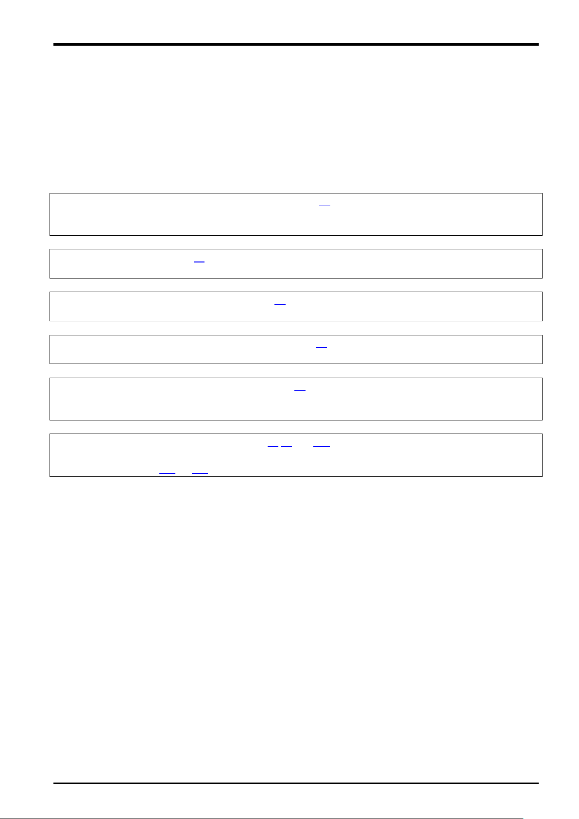
1 Using This Manual
1.1 Using This Manual
This manual is divided up in to the following sections, and describes how to use the force sense function, which
employs a force sense interface and force sense sensor. Refer to the "Instruction Manual" provided with the
robot controller for details on functionality and the operation methods for the standard robot controller.
Table 1-1: Instruction Manual content
2 Work Flow
3
4 Check Before Use
5
6
7
8
9
10 Application Examples
11 Language Specifications
12
13 Troubleshooting
Force Sensor
Attachment
Checking the
Connection and Settings
Function
Function
prepared. Check whether all the required products are
present, and check the controller, T/B, and RT-ToolBox2
heed to the precautions when using the robot with sensor
attached, that devices have been properly connected, and
that all settings have been specified correctly. Always check
sense function.
function.
Using This Manual 1-1

1 Using This Manual
Content
Force sense function
This is the name of the robot control function using a force sensor. It
functions.
Force sense control
This function uses real-time information from the force sense function to
control robot softness and the amount of force applied to workpieces.
Force sense detection
This function detects force sensor information, performs interrupt
interrupts occur.
Force sense log
This function obtains and displays force sensor and robot position
information.
Force control
This is a control method used to control robot force. Controls robot force
is used when pushing with constant force.
Stiffness control/limited
This is a robot control method used to control robot stiffness. Controls the
The limited stiffness control can restrict the force of the robot.
Force sensor
This sensor detects force and moment.
Force sense I/F unit
This unit takes in sensor information obtained from the force sensor and
passes it to the robot controller.
1.2 Terminology Used in This Instruction Manual
The following is a list of terminology used in this manual.
Table 1-2: Description of Terminology
consists of force sense control, force sense detection, and force sense log
processing, and retains force sense data and robot position data when
while offsetting position in order to obtain the specified reaction force. This
stiffness control
robot as though there is a spring on the robot hand flange surface. This
method is used for copying around workpieces and assembling flexible
objects.
1-2 Terminology Used in This Instruction Manual
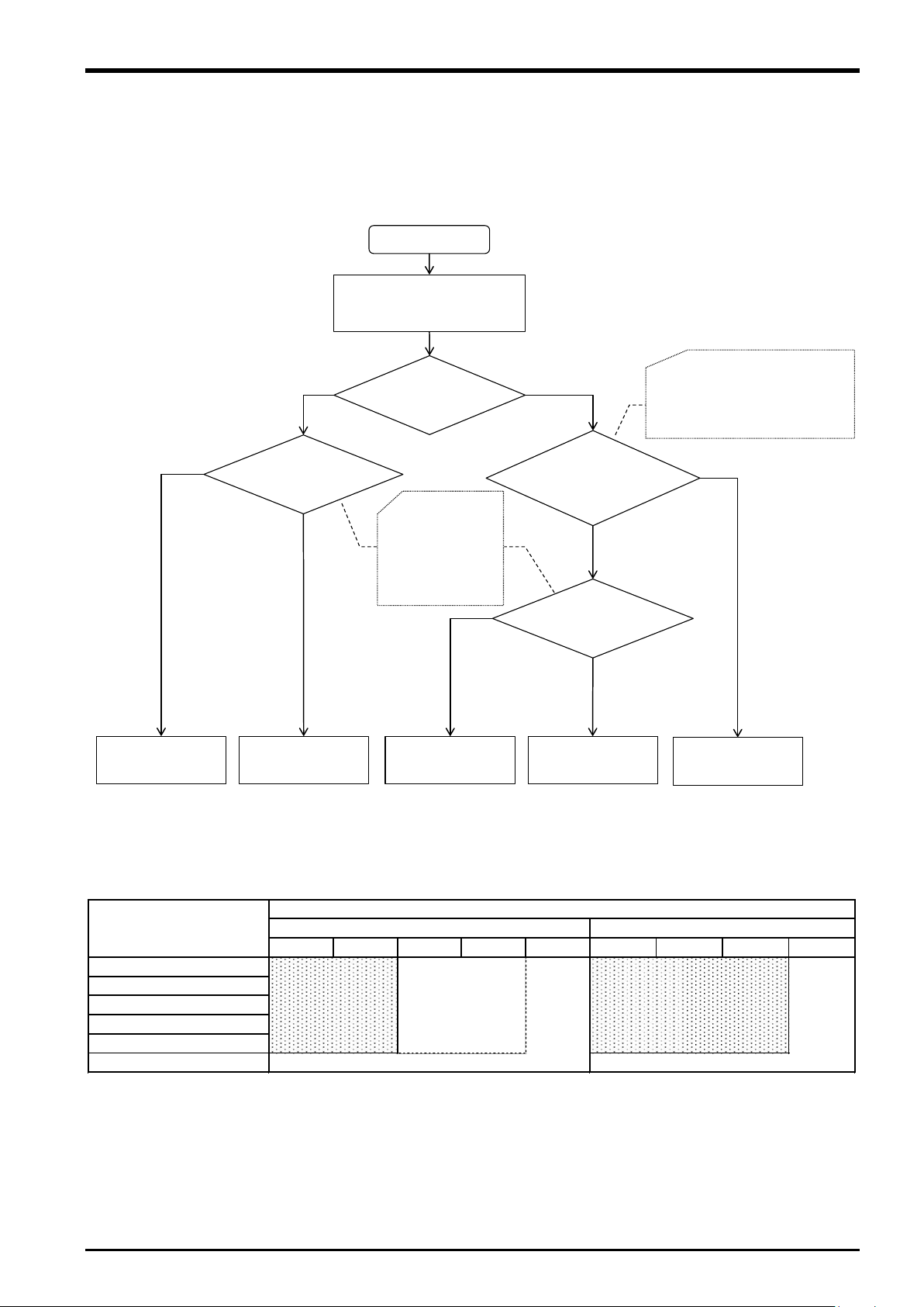
1 Using This Manual
Select force sensor by application
and robot of Table 1-3
Selected
force sensor
Moment beyond
4Nm is impressed
4F-FS001-W1000
4F-FS001-W200
4F-FS001-W1000
4F-FS001-W200
YES
NO
Moment beyond
4Nm is impressed
4F-FS001-W1000
Please contact
Mitsubishi Electric Corp.
4F-FS001-W200
YES
YES
NO
NO
Start
Tool shape and Hand own
weight by posture change
is also considered.
(Figure 1-2)
Resolution smaller than below is needed.
・Force:Approx. 0.15N(15.3gf)
・Moment:Approx. 0.0046Nm(0.47gfm)
Delicate work and detecting
minute power is needed.
RV-2F RV-4F RV-7F RV-13F RV-20F RH-3F RH-6F RH-12F RH-20F
Close tolerance fit
Phase focusing
Parts assembly
Test(Pressed/Pull-out)
Inset
Deburr/Polishing
Application
Robot
RV-F Series
RH-F Series
4F-FS001-W200
4F-FS001-W1000
4F-FS001-W200
4F-FS001-W1000
or
4F-FS001-W200
(Upward and
downward li mited)
4F-FS001-W1000
1.3 Select the Force Sensor
Selection flow of force sensor is indicated on below. Confirm the selection result here and the force sensor
specification of Chapter 3.6 , and please decide about the force sensor you use.
*1: If you want to use the force sensor with the RV-35/50/70F robot, please contact Mitsubishi Electric Corporation.
Fig. 1-1: Selection flow of force sensor
Table 1-3: First selection of force sensor
Select the Force Sensor 1-3
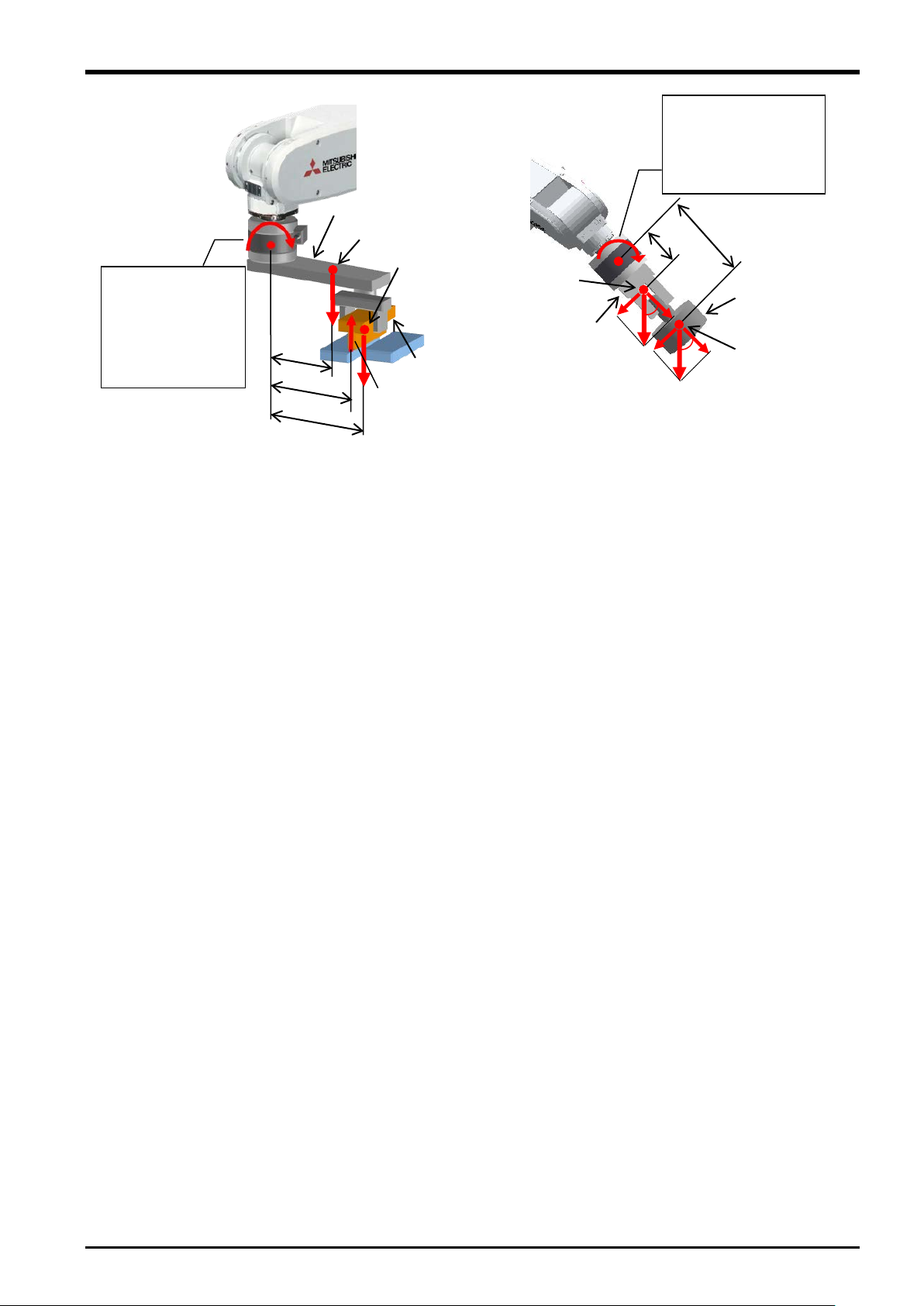
1 Using This Manual
(m)
Moment around force sensor coordinate origin (Nm)
M
1
(m)
L2(m)
of the hand
Center of
Tool W1 (kg)
Workpiece
Moment around force sensor coordinate
M
*g:gravity acceleration (m/sec2)
Tool W1 (kg)
Workpiece W2 (kg)
L
(m)
2
(m)
If tool shape is like
figure, force sensor
receives moment by
ool own weight or
θ
received moment by tool
When robot changes
posture, force sensor is
own weight.
t
pushing workpiece.
= W1×L1×g+W2×L2×g - F×L3
Fig. 1-2: Moment by the tool shape and a posture change
Center of gravity of the hand
Center of gravity of the Workpiece
L
3
L
Reactive force
F(N)
Center of gravity
:
L
W2(kg)
θ
gravity of the
Workpiece
origin (Nm):
= W1×sinθ×L1×g+W2×sinθ×L2×g
1-4 Select the Force Sensor
2 Work Flow
2 Work Flow
The work required to construct a system employing a force sensor is shown below. Refer to the following work
flow and carry out the work as described.
2.1 Flowchart
1. Force sense function system specifications...."See Chapter 3
Check the force sense function system configuration and function specifications before carrying out the
following work.
↓
2. Product check..."See Chapter 4
Check the purchased product and prepare the required parts.
↓
3. Force sensor attachment method..."See Chapter 5
Attach the force sensor to the robot.
↓
4. Device connection, wiring, setting methods..."See Chapter 6
Connect the force sense interface unit and force sensor, and set the required default parameter settings.
↓
5. Connection and setting check method..."See Chapter 7
Check whether the connections and settings are correct. Always check connections and settings before using
the force sense function.
↓
6. Using the force sense function..."See Chapters 8 , 9 , and 10
Describes how to use the force sense function. Use the force sense function while referring to the detailed
descriptions in Chapters 11 and 12 .
of this manual."
of this manual."
of this manual."
of this manual."
of this manual."
of this manual."
Flowchart 2-5

3 Force Sense Function System Specifications
3 Force Sense Function System Specifications
3.1 What is the Force Sense Function?
The "force sense function" uses force sensor information with 6 degrees of freedom to provide the robot with a
sense of its own force. Using dedicated commands and status variables compatible with the robot program
language (MELFA-BASIC V) facilitates work requiring minute power adjustments and power detection that was
not possible on past robots.
<Main features>
(1) Robots can be controlled softly and operated while copying applicable workpieces.
(2) Robots can be operated while pushing in the desired direction with a fixed amount of force.
(3) Robot softness and contact detection conditions can be changed during movement.
(4) Contact status can be detected and interrupt processing performed.
(5) Position information and force information at the time of contact can be performed.
(6) Force data synchronized with position data can be saved as log data.
(7) Log data can be displayed in a graph using RT ToolBox2.
(8) Log data files can be transferred to an FTP server.
3-6 What is the Force Sense Function?
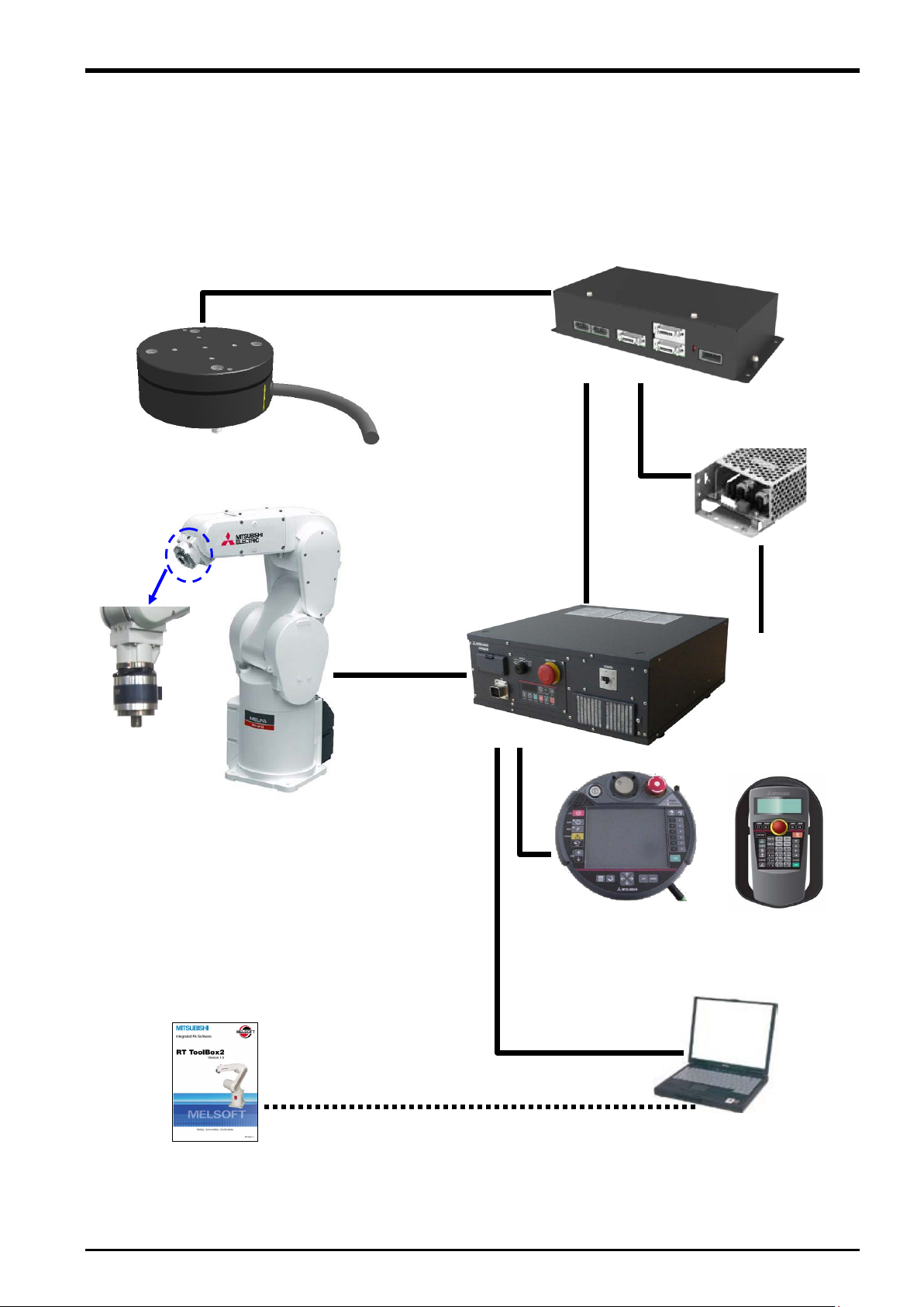
3 Force Sense Function System Specifications
Force sense interface unit
(2F-TZ561)
Computer
Machine cable
Robot controller
Teaching pendant
R32/33TB)
RT ToolBox2
24 VDC output cable
(2F-PWRCBL-01)
(Force sensor
attachment
example)
Robot
Force sensor
Serial cable between unit and sensor
(2F-FSCBL1-05)
LAN, USB
SSCNETIII
cable
3.2 System Configuration
The device configuration required to use the force sense function is shown below.
(1F-FS001-W200/1F-FS001-W1000)
3D-11C-WINE
3D-12C-WINE
Fig. 3-1: Force sense function system configuration drawing
24 VDC power
supply
(2F-PWR-01)
24 VDC input power
supply cable
(2F-PWRCBL-02)
(R56/57TB or
System Configuration 3-7

3 Force Sense Function System Specifications
Item
Function Details
Remarks
Applicable robot
RV-F Series / RH-F Series
(*1)
Robot program language
MELFA-BASIC V (with dedicated force sense
function commands)
Force
Stiffness control
Function used to control robot softly (Sets
stiffness coefficients, damping coefficients.)
Limited stiffness
Function used to control robot softly (Sets
This function can be
lator.
Force control
This function controls the robot while pushing
with specified force.
Control
change
This function changes the control characteristics
movement.
Force
Interrupt
Interrupt processing can be performed using the
moment are exceeded.
Data latch
This function obtains the force sensor and robot
position at the time of contact.
Data referencing
This function displays force sensor data and
retains maximum values.
Force
Synchronization
This function obtains force sensor information
data.
Start/end triggers
Logging start and end commands can be
specified in the robot program.
FTP transfer
This function transfers obtained log files to an
FTP server.
Gravity offset cancel
Gravity offset cancel is a function that the offset
calibration.
This function can be
R32TB/R33TB
Force sense
control (TB)
Enables/disables force sensor control and sets
control conditions while jogging.
Force sense
monitor
Displays sensor data and the force sense control
setting status.
Teaching position
search
This function searches for the contact position.
R56TB/R57TB
Force sense
control (TB)
Enables/disables force sense control and sets
control conditions while jogging.
Force sense
monitor
Displays sensor data and the force sense control
setting status.
Teaching position
search
This function searches for the contact position.
Parameter setting
screen
Dedicated force sense function parameter setting
screen
3.3 Force Sense Function Specifications
The force sense function specifications are as follows.
Table 3-1: Force sense function specifications
sense
control
control
stiffness coefficients, damping coefficients.)
This function can restrict the force of the robot.
used with controller
version R6h/S6h or
sense
detection
Controller
sense
log
characteristics
execution
data
of force control and stiffness control during robot
status at the point the specified force and
synchronized with position information as log
cancel in response to a change in the direction of
gravity applied to the force sensor by hand load
at the time of posture change.To use this
function, it is necessary to estimate the bias value
of the force sensor, position of the senter of
gravity and the mass of hand load by the force
used with controller
version R6h/S6h or
lator.
Corresponding robot
of this function has
become RV-F series.
3-8 Force Sense Function Specifications

3 Force Sense Function System Specifications
Item
Function Details
Remarks
RT ToolBox2
Waveform data
display
Displays force sensor and position data.
Oscillograph
Displays the data which is retrieved from a force
This function can be
version 3.00A or later
Parameter setting
screen
Dedicated force sense function parameter setting
screen
Force sensor
Executes the force sensor calibration in this
This function can be
version 3.00A or later
sensor.
calibration screen
screen.
*1: When using the FH-F series, you should purchase the sensor attachment adaptor separately.
used in the RT
ToolBox software
used in the RT
ToolBox software
Force Sense Function Specifications 3-9
3 Force Sense Function System Specifications
Item
Unit
Specification Value
Remarks
Model - 2F-TZ561
Force
sensor
No. of connected
sensors
Interface
RS-422
For sensor connection
SSCNET III
For robot controller and additional axis amp
connection
Power
Input voltage
range
There should be no momentary power
Power
consumption
Includes power supply capacity for force
External dimensions
mm
225(W) x 111(D) x 48(H)
Does not include protrusions.
Weight
kg
Approx. 0.8
Construction
Panel installation, open
type
IP20
Operating temperature range
°C
0 to 40
Relative humidity
%RH
45 to 85
There should be no dew condensation.
Paint color Dark gray
Munsell No.: 3.5PB3.2/0.8
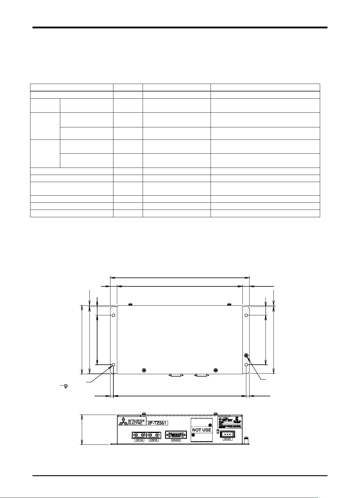
225
203
111
108
80
14
2
48
215
(5)
(11)
2
14
5
108
80
4.5 hole
4
FG (M3 screw)
11
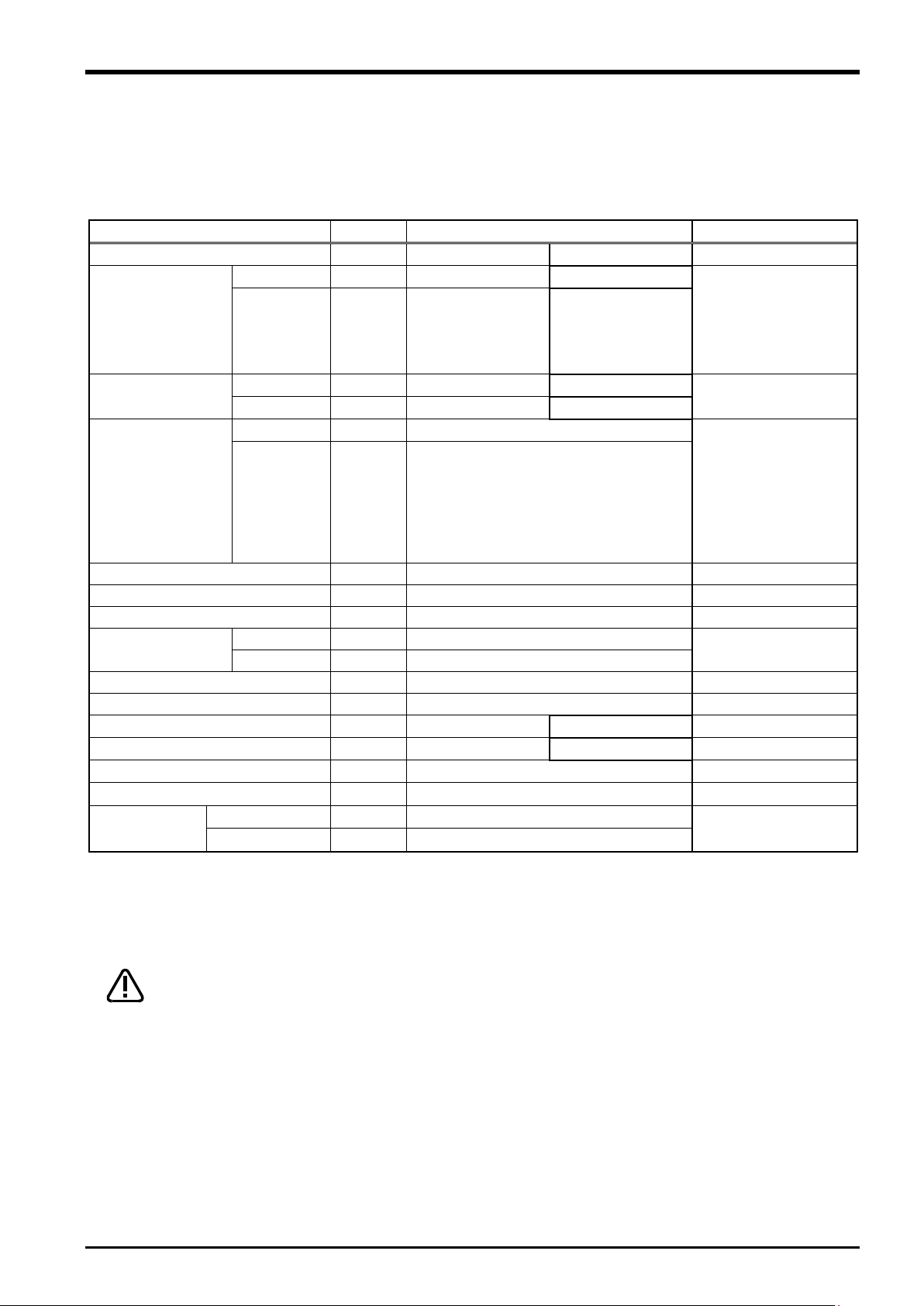
3.4 Force Sense Interface Unit Specifications
The force sense interface unit specifications are as follows.
Table 3-2: Force sense interface unit specifications
sensors 1
ch 1
ch 2
supply
VDC
W 25
24 ±5%
interruptions or momentary voltage drops.
sensor unit.
3.4.1 Force Sense Interface Unit External Dimensions
Outline drawings of the force sense interface unit are shown below.
3-10 Force Sense Interface Unit Specifications
Fig. 3-2: Force sense interface unit outline drawings
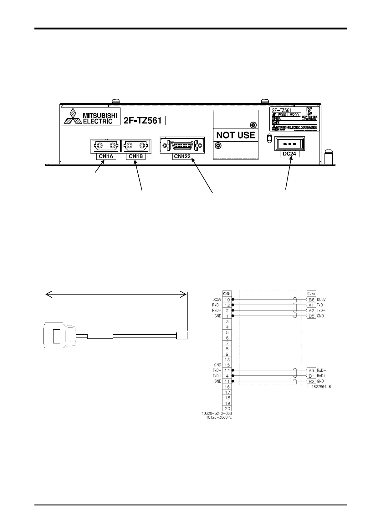
3 Force Sense Function System Specifications
CN1B
connection)
DC24 connector
CN1A
connection)
CN422
connection)
5000 mm
Connection diagram
3.4.2 Name of Each Force Sense Interface Unit Part
The name of each force sense interface unit part is as follows.
(for robot controller
(for additional axis amp
3.4.3 Force Sensor Connection Cable
(for force sensor
(for power supply)
Force Sense Interface Unit Specifications 3-11
3 Force Sense Function System Specifications
Item
Unit
Specification Value
Remarks
Model - 2F-PWR-01
Input
Voltage
VAC
85 to 264
current
1.3 typ.
ACIN 100V
0.7 typ.
ACIN 200V
Frequency
Hz
50 or 60 (47 to 63)
Output
Rated voltage
VDC
24
Rated current A 4.3
Voltage setting
accuracy
VDC
23.00 to 25.00
External dimensions
mm
72(W) x 185(D) x 45(H)
Weight g 480
Construction
Panel installation, open
type
IP20
Operating temperature range
°C
-10 to 70
Relative humidity
%RH
20 to 90
There should be no dew condensation.
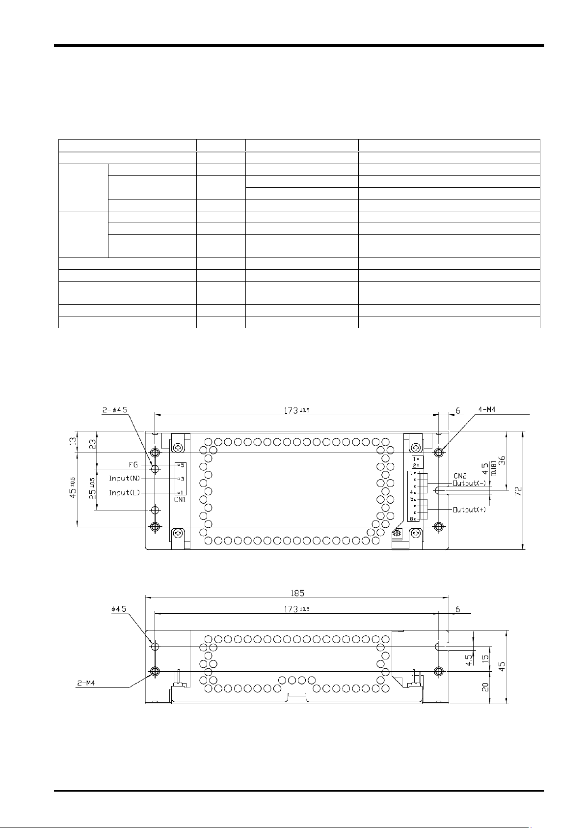
3.5 24 VDC Power Supply Specifications
The 24 VDC power supply specifications are as follows.
Table 3-3: 24 VDC power supply specifications
A
3.5.1 24 VDC Power Supply Outline Drawing
3-12 24 VDC Power Supply Specifications
Fig. 3-3: 24 VDC power supply outline drawing
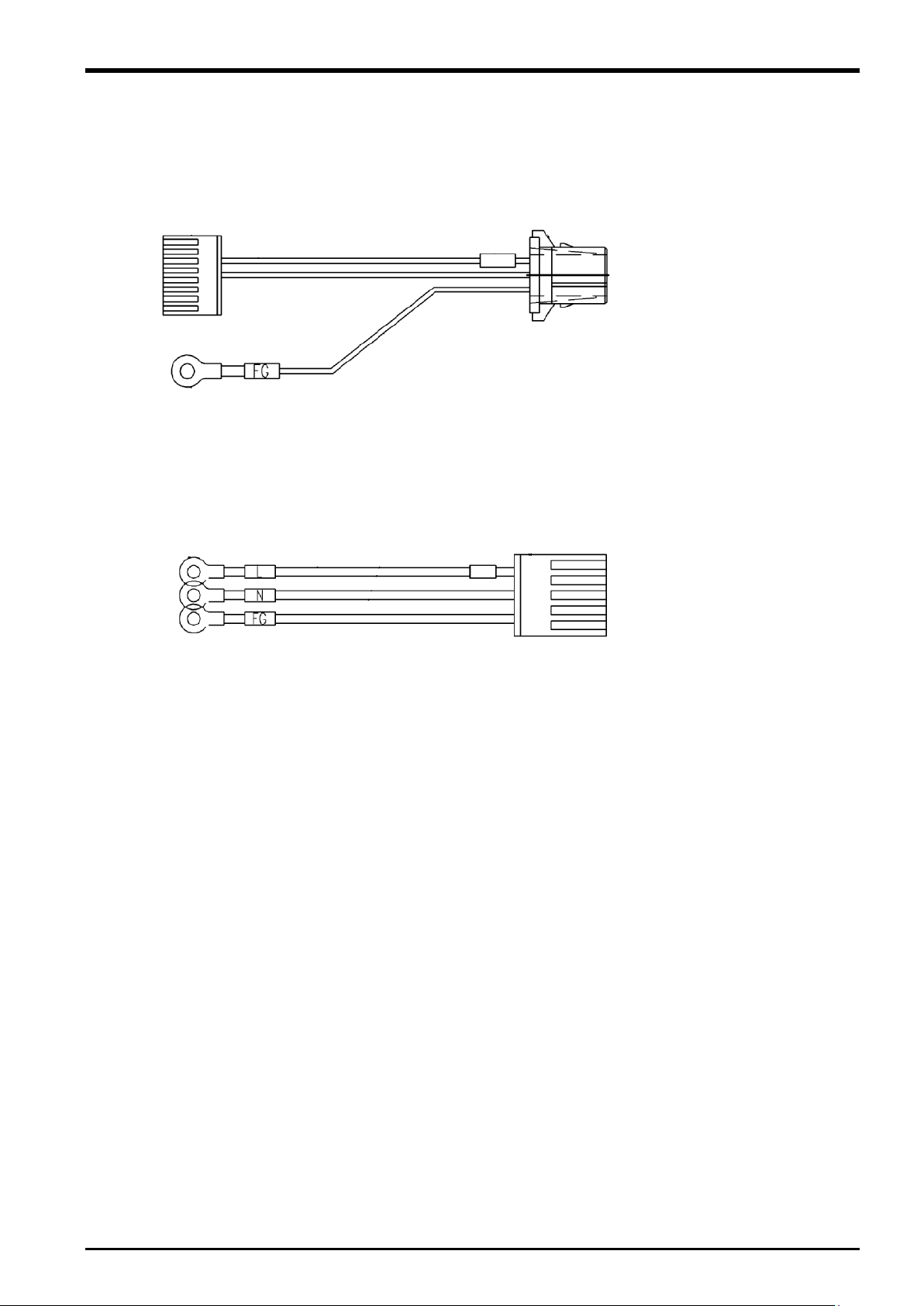
(Pin assignment)
3: GND
(Pin assignment)
5: FG
3.5.2 24 VDC Output Cable
3.5.3 24 VDC Input Cable
3 Force Sense Function System Specifications
1: +24 V
2: 0 V
1: L
3: N
24 VDC Power Supply Specifications 3-13
3 Force Sense Function System Specifications
Item
Unit
Specification Value
Remarks
Model
-
1F-FS001-W200
1F-FS001-W1000
Fx, Fy, Fz N 200
1000
Be sure to set the
value) parameter.
Fx, Fy, Fz
N
Approx. 0.03
Approx. 0.15
Mx, My, Mz
Nm
Approx. 0.0006
Approx. 0.0046
Fx, Fy, Fz
N
0.3
This value can be
R6h/S6h or later)
Linearity
%FS 3
Hysteresis
%FS 3
Other axis sensitivity
%FS 5
Fx, Fy, Fz
%FS/°C
±0.2
Mx, My, Mz
%FS/°C
±0.2
Consumption current
mA
200
Output form - RS422
Weight (sensor unit)
g
360
580
External dimensions
mm
80 x 32.5
90 x 40
See outline drawing.
Material - Aluminum alloy
Color
-
Black
Temperature
°C
0 to 50
Humidity
%RH
95 or less
Caution
When a load beyond the rated load is applied repeatedly, distortion occurs
gradually inside the sensor. Therefore, the force does not be detected precisely.
Use the force sensor with a load within the rated range.
3.6 Force Sensor Specifications
The force sensor specifications are as follows.
Table 3-4: Force sensor specifications
Rated load (*1)
Mx, My, Mz Nm 4 30
value within the rated
load to the
FSLMTMX (force
sensor permissible
Resolution
changed by the
FSMINCTL (force
Minimum control
force (*2)
Zero temperature
properties
Operating
environment
*1: When 1F-FS001-W200 is used with RV-7/13/20F robot, the moment beyond the moment rated load of the force sensor is
applied if the tool/workpiece of the robot's maximum load mass is grasped and its hand posture is set vertically to the
installation surface (the robot set on the floor). Use the force sensor with the hand posture at which the moment does not
exceed the moment rated load (for example, with the hand posture facing downward).
*2: Minimum value of force or moment for force sense control.
Mx, My, Mz Nm 0.03
∅
∅
sensor minimum
control force)
parameter.
(Controller Ver.
3-14 Force Sensor Specifications
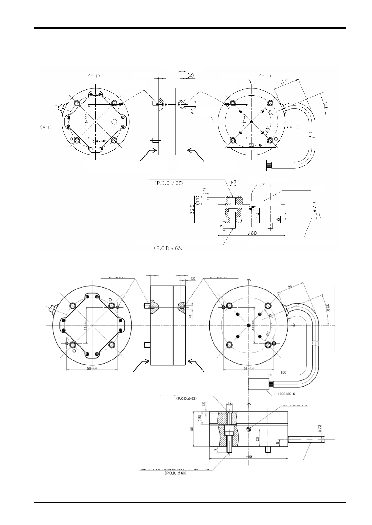
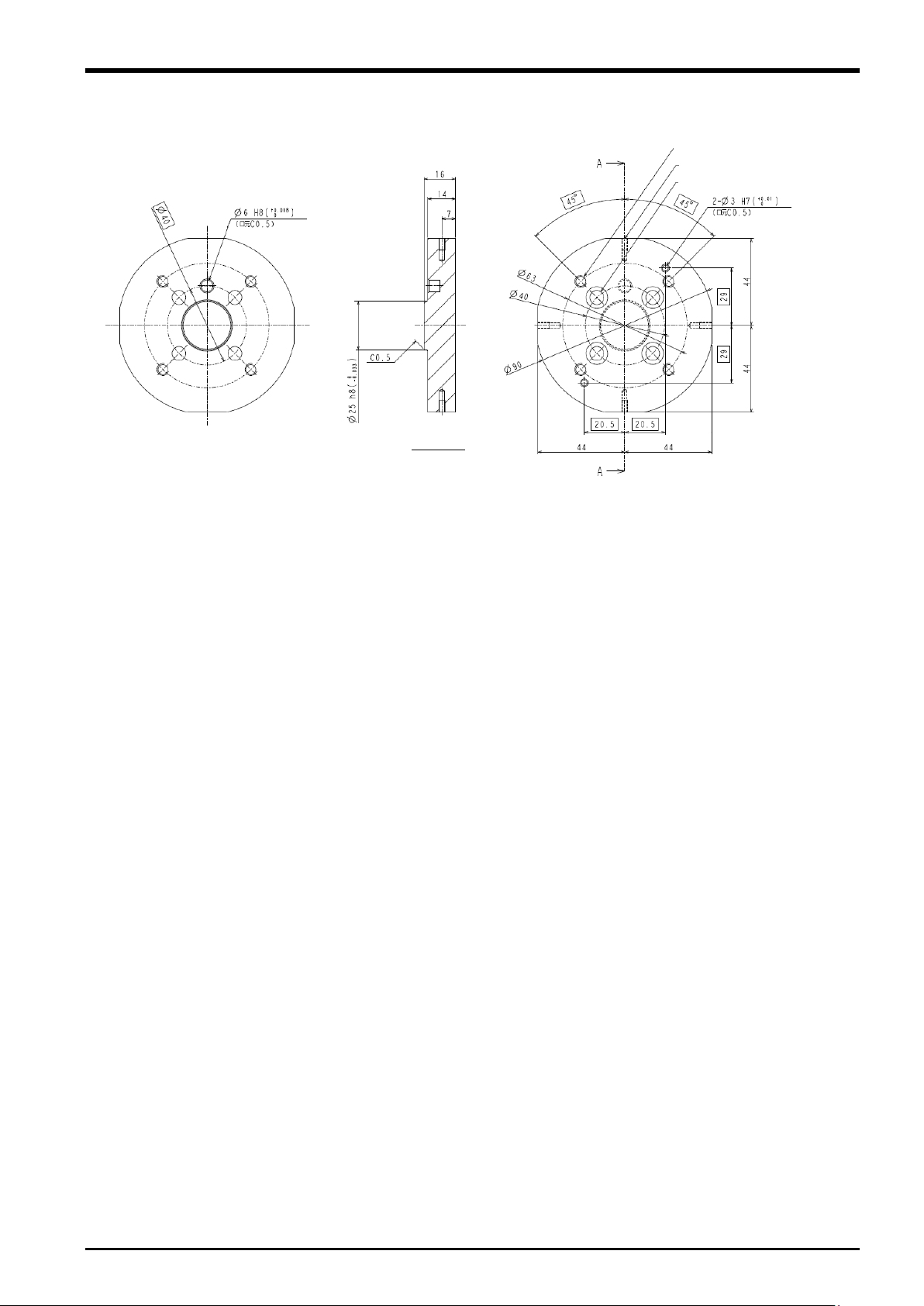
3.6.1 Force Sensor External Dimensions
Pin hole for positioning
H7 effective depth 4
Pin hole for positioning
H7 effective depth 4
(Detection axis Y)
(Detection
Tap hole for attachment 4-M6×1.0
Low head bolt for mounting sensor 4-M6×1.0
(Cable: MISUMI NA20276RSB-26-5P)
(Sensor detection center)
(Detection axis Y)
T
Attachment adapter mounting surface
Positioning pin hole
2-φ3H7, depth 4
H7 effective depth 4
H7 effective depth 4
(Detection axis Y)
Tap hole for attachment 4-M6×1.0
Low head bolt for mounting sensor 4-M6×1.0
(Cable: MISUMI NA20276RSB-26-5P)
(Sensor detection center)
(Detection axis Y)
T
Attachment adapter mounting surface
Positioning pin hole
2
(Detection
axis X)
(Detection axis Z)
Outline drawings of the force sensor are shown below.
ool mounting surface
3 Force Sense Function System Specifications
-φ3H7, depth 4
Fig. 3-4: Force sensor outline drawing (1F-FS001-W200)
2-φ3H7
ool mounting surface
2-φ3H7
axis X)
Fig. 3-5: Force sensor outline drawing (1F-FS001-W1000)
Force Sensor Specifications 3-15
3 Force Sense Function System Specifications
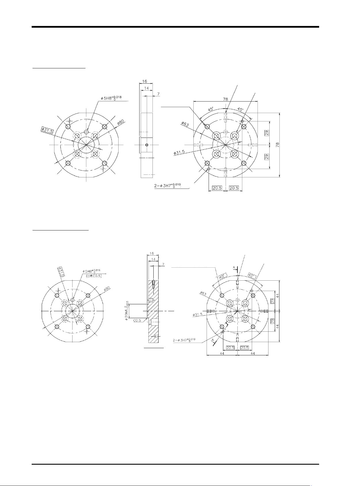
depth 6
4 – M6 screw through-hole,
bo
depth 5
4 – 5.5 cut, ∅10 through-hole depth 10
(at equidistant points on circumference)
(at equidistant points on
circumference)
4 – M3 screw depth 6, bottom hole depth 11
Section A-A
depth 6
4 – M6 screw
through-hole, bottom
hole 4.9
depth 5
(sensor positioning pin hole)
4 – 5.5 cut, ∅10 through-hole depth 10
(at equidistant points
on circumference)
(at equidistant points on
circumference)
4 – M3 screw depth 6
3.6.2 Sensor Attachment Adapter External Dimensions
Outline drawings of the sensor attachment adapter are shown below.
For 1F-FS001-W200
Fig. 3-6: Sensor attachment adapter outline drawings (for RV-2/4/7F)
For 1F-FS001-W1000
ttom hole 4.9
3-16 Force Sensor Specifications
Fig. 3-7: Sensor attachment adapter outline drawings (for RV-2/4/7F)
3 Force Sense Function System Specifications
depth 6
4 – M6 screw through-hole, bottom hole 4.9
depth 5
4 – 5.5 cut, ∅11 through-hole depth 8
(at equidistant points on circumference)
4 – M3 screw depth 6, bottom hole
depth 11
Section A-A
(at equidistant points on circumference)
Fig. 3-8: Sensor attachment adapter outline drawings (for RV-13/20F)
Force Sensor Specifications 3-17

3 Force Sense Function System Specifications
Coordinate System Name
Description
Force sense coordinate system
(mechanical interface)
Coordinate system that forms reference for calibration
(See section 6.5.2 for details on calibration.)
Force sense coordinate system
(tool)
Coordinate system for force sense function
(when tool selected)
Force sense coordinate system (XYZ)
Coordinate system for force sense function
(when XYZ selected)
Force sensor coordinate system
Coordinate system for force sensor
3.7 Coordinate System Definition
The force and moment coordinate systems used with the force sense function are summarized in "Table 3-5".
Table 3-5: Force sense coordinate system list
A definition of each coordinate system is described below.
3-18 Coordinate System Definition
 Loading...