

Page 1

ENGINE
4D68
CONTENTS
11A-0-1
GENERAL INFORMATION 11A-0-3
1. SPECIFICATIONS 11A-1-1
SERVICE SPECIFICATIONS 11A-1-1
REWORK DIMENSIONS 11A-1-3
TORQUE SPECIFICATIONS 11A-1-4
NEW TIGHTENING METHOD - BY USE OF BOLTS
TO BE TIGHTENED IN PLASTIC AREA 11A-1-7
SEALANT 11A-1-7
FORM-IN-PLACE GASKET 11A-1-8
2. SPECIAL TOOLS 11A-2-1
3. DRIVE BELT AND GLOW PLUG 11A-3-1
4. TIMING BELT 11A-4-1
5. GLOW PLUG, FUEL INJECTION PUMP
AND INJECTION NOZZLE 11A-5-1
6. INTAKE AND EXHAUST MANIFOLDS 11A-6-1
7. WATER PUMP, THERMOSTAT, HOSE AND PIPES 11A-7-1
.................................................
...............................................
.....................................
..........................................
............................
.................................
.............................
................
..............................
..........................................
..........................
................................
....................
......
8. ROCKER ARMS, ROCKER SHAFT AND CAMSHAFT 11A-8-1
9. CYLINDER HEAD, VALVES AND VALVE SPRINGS 11A-9-1
10. FRONT CASE, COUNTERBALANCE SHAFTS
AND OIL PAN 11A-10-1
11. PISTONS AND CONNECTING RODS 11A-11-1
12. CRANKSHAFT, CYLINDER BLOCK AND FLYWHEEL 11A-12-1
E
Dec. 1996Mitsubishi Motors Corporation
...............................................
.....................
PWEE9609
...
.....
...
Page 2

11A-0-2
NOTES
E
Dec. 1996Mitsubishi Motors Corporation
PWEE9609
Page 3
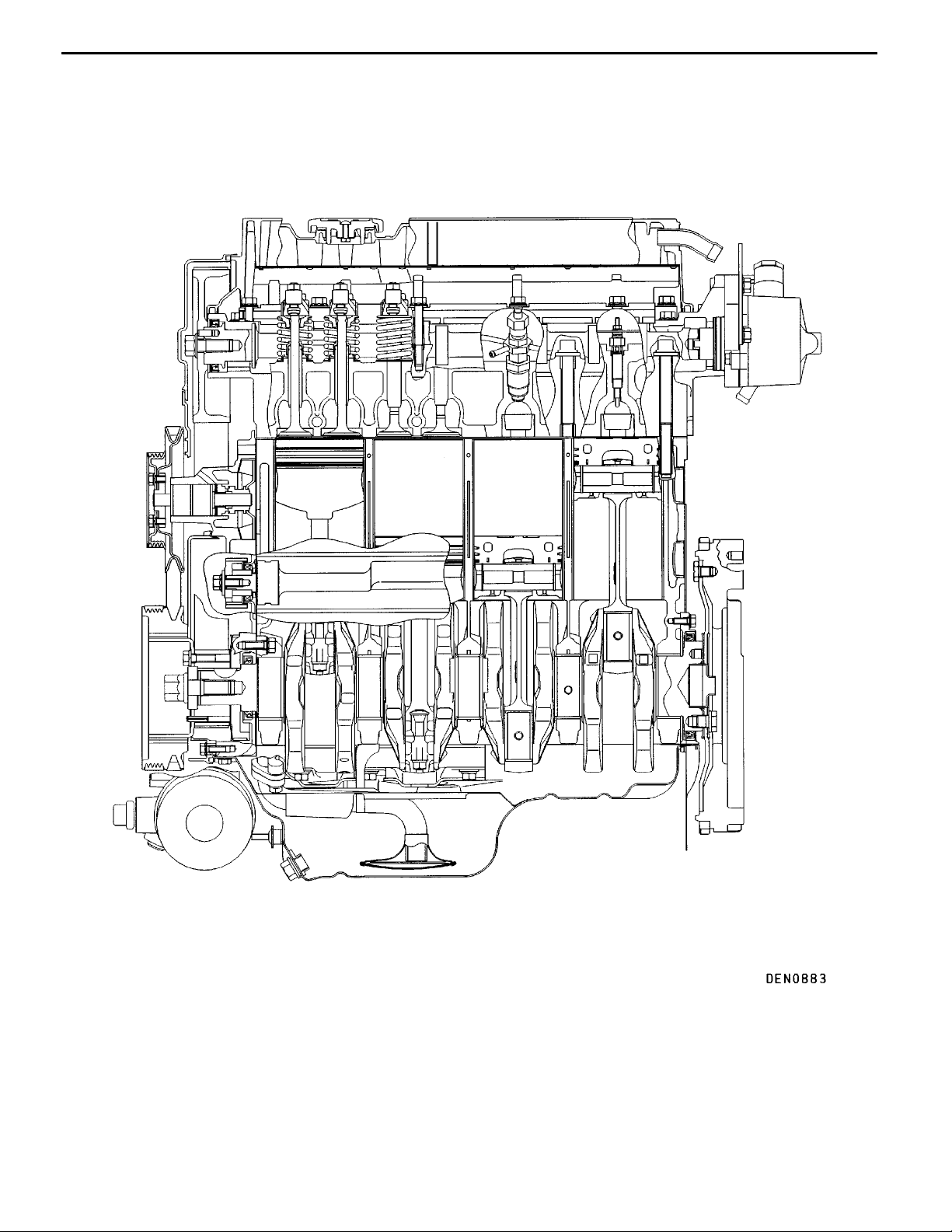
4D68 ENGINE (E-W) -
GENERAL INFORMATION
SECTIONAL VIEW OF ENGINE
General Information
11A-0-3
E
Dec. 1996Mitsubishi Motors Corporation
PWEE9609
Page 4
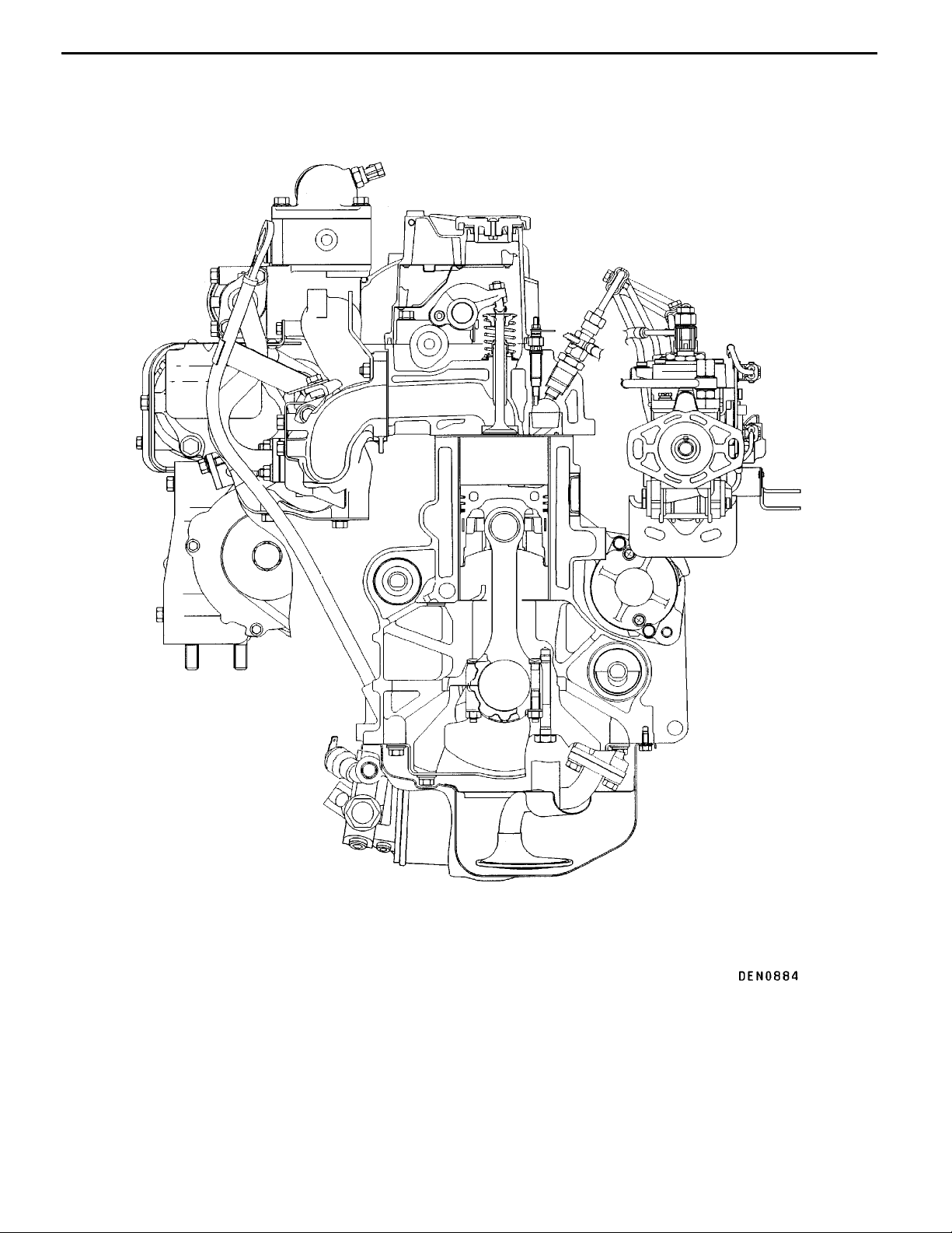
11A-0-4
4D68 ENGINE (E-W) -
SECTIONAL VIEW OF ENGINE
General Information
E
Dec. 1996Mitsubishi Motors Corporation
PWEE9609
Page 5
4D68 ENGINE (E-W) -
General Information
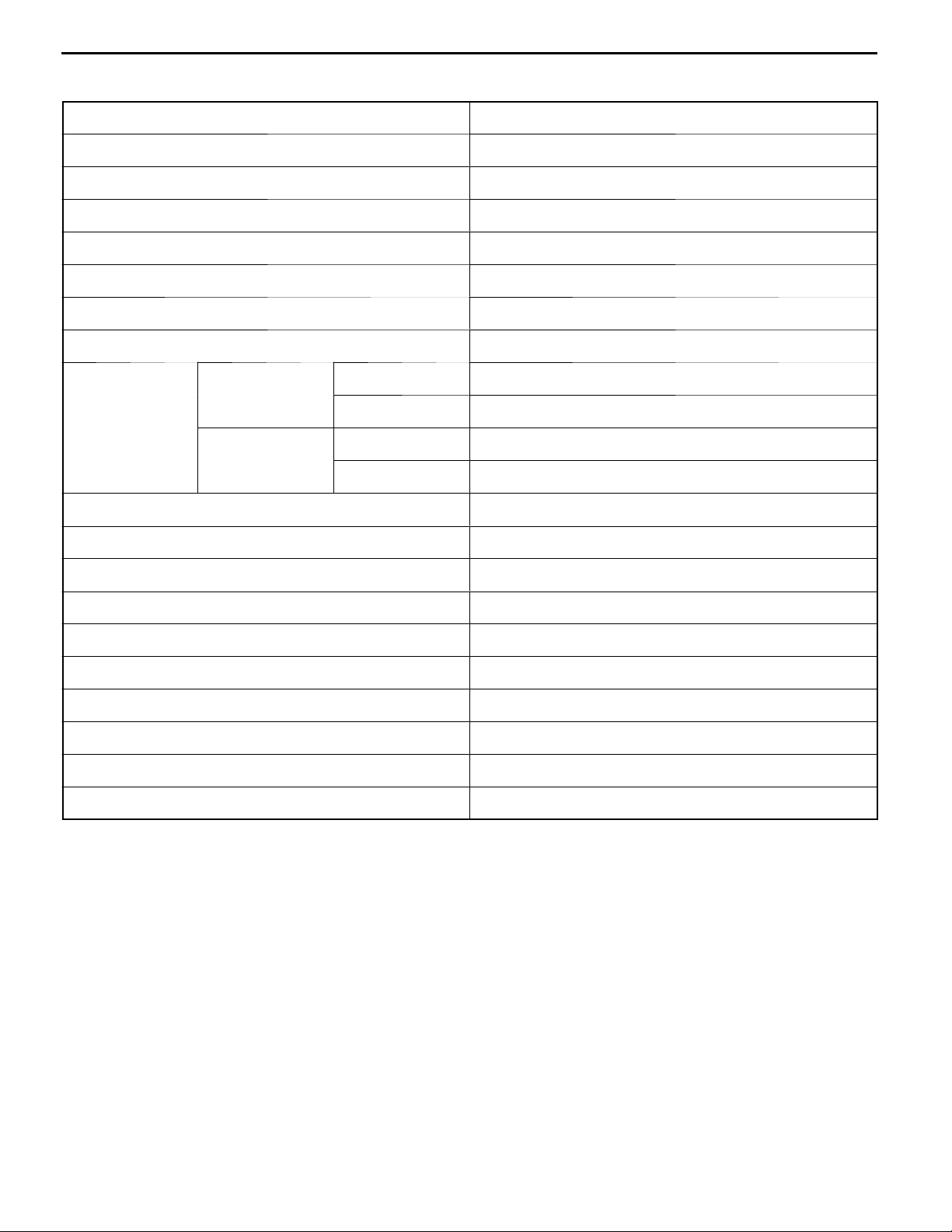
GENERAL SPECIFICATIONS
Descriptions Specifications
Type Diesel engine
Number of cylinders 4 in-line
Combustion chamber Swirl chamber
11A-0-5
Total displacement dm
Cylinder bore mm 82.7
Piston stroke mm 93
Compression ratio 22.4
V alve timing Intake valve Opens (BTDC) 20°
Lubrication system Pressure feed, full-flow filtration
Oil pump type External gear type
Cooling system Water-cooled
Water pump type Centrifugal impeller type
EGR type Single type
Fuel system Electronic control distributor-type injection pump
3
Closes (ABDC) 48°
Exhaust valve Opens (BBDC) 54°
Closes (ATDC) 22°
1.998
Supercharging Turbocharger
Rocker arm Roller type
Adjusting screw Elephant foot type
Oil lever sensor Provided
E
Dec. 1996Mitsubishi Motors Corporation
PWEE9609
Page 6
4D68 ENGINE (E-W) -
Specifications
1. SPECIFICATIONS
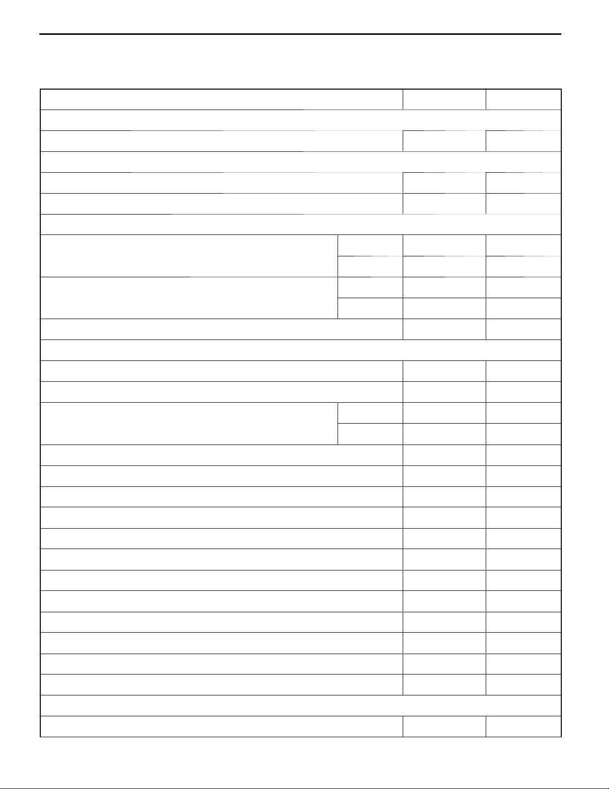
SERVICE SPECIFICATIONS
Item Standard value Limit
Drive belt and glow plug
Glow plug resistance W 0.5 -
Timing belt
Timing belt deflection mm 4.0- 5.0 -
Timing belt “B” deflection mm 5.0- 7.0 -
Rocker arms, rocker shaft and camshaft
Camshaft cam height mm Intake 41.90 41.40
Exhaust 41.96 41.46
Valve clearance (on cold engine) mm Intake 0.25 -
Exhaust 0.35 -
11A-1-1
Camshaft journal O.D. mm 30.0 -
Cylinder head, valves and valve springs
Cylinder head gasket surface flatness mm Within 0.03 0.2
Cylinder head overall height mm 86.9- 87.1 -
Valve overall length mm Intake 114.05 113.55
Exhaust 113.80 113.30
Thickness of valve head (margin) mm 1.5 0.7
Valve stem O.D. mm 6.0 -
Valve face angle 45° - 45.5° -
V alve stem to guide clearance mm 0.05- 0.09 0.15
V alve spring free length mm 49.1 48.1
V alve load/installed height N/mm 240/37.9 -
V alve spring out-of-squareness 2° or less Max. 4°
Valve seat valve contact width mm 0.9- 1.3 -
V alve stem projection mm 43.45 43.95
Valve guide I.D. mm 8.0 -
V alve guide projection from cylinder head upper surface mm 15 -
Cylinder head bolt shank length mm - 119.7
Front case, counterbalance shafts and oil pan
Oil cooler by-pass valve dimension (L) [Normal temperature] mm 34.5 -
E
Dec. 1996Mitsubishi Motors Corporation
PWEE9609
Page 7
11A-1-2
Item LimitStandard value
4D68 ENGINE (E-W) -
Specifications
Oil cooler by-pass valve dimension (L) [by-pass hole closing temperature
(97 - 103°C or more)] mm
Oil pump side clearance Drive gear 0.08 - 0.14 -
Driven gear 0.06- 0.12 -
Pistons and connecting rods
Piston O.D. mm 82.7 -
Piston ring to piston ring groove clearance mm No. 1 0.05- 0.07 0.15
No. 2 0.05- 0.07 0.15
Piston ring end gap mm No. 1 0.20- 0.32 0.8
No. 2 0.35- 0.50 0.8
Oil ring 0.10 - 0.30 0.8
Piston pin O.D. mm 25.0 -
Crankshaft pin oil clearance mm 0.02 - 0.05 0.1
Connecting rod big end side clearance mm 0.10- 0.25 0.4
Connecting rod bushing I.D. mm 25.015- 25.025 -
40.0 -
Connecting rod bushing bend (Parallelism between big end center line and small
end center line) mm
Connecting rod bushing twist (Deflection between big end center line and small
end center line) mm
Crankshaft, cylinder block and flywheel
Crankshaft end play mm 0.05- 0.18 0.25
Crankshaft journal O.D. mm 57.0 -
Crankshaft pin O.D. mm 45.0 -
Crankshaft journal oil clearance mm 0.02- 0.04 0.1
Cylinder block gasket surface flatness mm 0.05 0.1
Cylinder block overall height mm 235 -
Cylinder bore I.D. mm 82.70- 82.73 -
Cylinder conicity mm 0.01 -
Piston to cylinder clearance mm 0.03- 0.05 -
Cylinder sleeve press-fitting force N 2,200 or more -
0.05 -
0.1 -
Piston projection mm 0.823 -
E
Dec. 1996Mitsubishi Motors Corporation
PWEE9609
Page 8
4D68 ENGINE (E-W) -
Specifications
REWORK DIMENSIONS
Item Standard value Limit
Cylinder head, valves and valve springs
Cylinder head oversize valve guide hole 0.05 O.S. 13.050- 13.068 (both intake and exhaust) mm
0.25 O.S. 13.250- 13.268 -
0.50 O.S. 13.500- 13.518 -
Cylinder head oversize intake valve seat ring hole mm 0.3 O.S. 38.300 - 38.325 -
0.6 O.S. 38.600 - 38.625 -
Cylinder head oversize exhaust valve seat ring hole mm 0.3 O.S. 34.300 - 34.325 -
0.6 O.S. 34.600 - 34.625 -
NOTE
O.D.: Outer diameter
I.D.: Inner diameter
O.S.: Oversize diameter
11A-1-3
E
Dec. 1996Mitsubishi Motors Corporation
PWEE9609
Page 9
11A-1-4
4D68 ENGINE (E-W) -
Specifications
TORQUE SPECIFICATIONS
Items Nm
Drive belt and glow plug
Oil level gauge guide bolt 13
Pulley bolt (for power steering pump drive) 9
Alternator brace bolt 23
Lock bolt 23
Adjusting bolt 10
Alternator pivot nut 44
Crankshaft pulley bolt 25
Glow plug 18
Glow plug nut 1.8
Timing belt
Timing belt cover Flange bolt 11
Washer bolt 9
Crankshaft position sensor bolt 9
Timing belt tensioner bolt 48
Tensioner spring bolt 13
Timing belt idler pulley bolt 48
Camshaft sprocket bolt 88
Injection pump sprocket flange bolt 9
Injection pump sprocket nut 83
Crankshaft bolt 118
Oil pump sprocket nut 54
Tensioner “B” bolt 18
Counterbalance shaft sprocket bolt 45
Timing belt rear cover bolt 11
Engine support bracket bolt and nut 49
Glow plug, fuel injection pump and injection nozzle
Injection pipe 29
Injection pipe clamp bolt 5
Fuel pipe bolt 13
Engine hanger bolt 18
Fuel injection pump bolt 23
Fuel injection pump nut 18
Fuel injection pump stay bolt 35
Fuel return pipe nut 29
E
Dec. 1996Mitsubishi Motors Corporation
PWEE9609
Page 10
4D68 ENGINE (E-W) -
Items Nm
Injection nozzle 54
Fuel injection pump bracket nut 23
Intake and exhaust manifold
Air temperature sensor 14
Air intake fitting bolt 17
EGR valve bolt 24
EGR pipe bolt and nut 17
Turbocharger heat protector bolt M8 13
Exhaust fitting heat protector bolt 13
Water pipe “A” and “B” eye bolt 30
Water pipe “A” and “B” bolt 10
Oil pipe eye bolt 16
Specifications
M6 11
11A-1-5
Exhaust fitting bolt and nut 59
Oil return pipe bolt 9
Heat protector front and rear bolt 13
Turbocharger assembly bolt 59
Exhaust manifold bolt and nut 29
Alternator brace stay bolt 23
Intake manifold bolt and nut 17
Water pump, thermostat, hose and pipe
Oil pipe eye bolt 16
Oil return pipe eye bolt 17
Oil return pipe bolt 9
Engine coolant temperature sensor 35
Engine coolant temperature gauge unit 11
Cover bolt 19
Water pump bolt 13
Water inlet pipe bolt 12
V acuum pump bolt 22
Water inlet fitting bolt 23
Water outlet fitting bolt 12
Thermostat housing bolt 23
Rocker arms, rocker shaft and camshaft
Rocker cover bolt 6
Rocker shaft bolt 29
E
Dec. 1996Mitsubishi Motors Corporation
PWEE9609
Page 11
11A-1-6
Items Nm
Adjusting nut 15
Camshaft bearing cap bolt M8 ¢ 25, M8 ¢ 40 20
Cylinder head, valves and valve springs
Cylinder head bolt 90
Front case, counterbalance shafts and oil pan
Drain plug 39
Oil level sensor bolt 9
Oil pan bolt 7
Oil screen bolt 19
4D68 ENGINE (E-W) -
Specifications
M8 ¢ 55 29
¯
Fully loosen
¯
40 + 90° +90°
Oil cooler by-pass valve 54
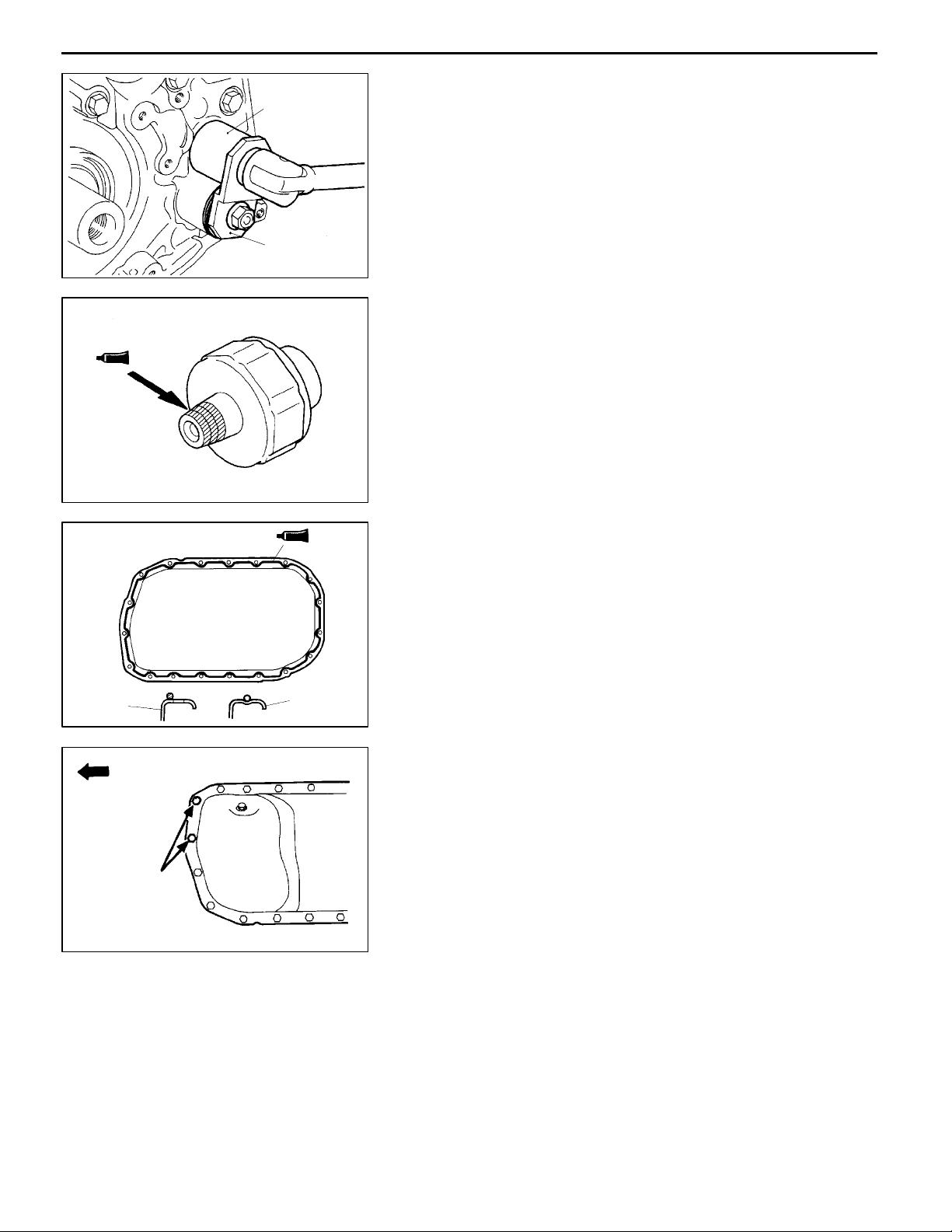
Oil pressure switch 10
Relief plug 44
Oil filter bracket bolt 18
Plug 23
Flange bolt 36
Front case bolt 24
Oil pump cover Bolt 16
Screw 10
Pistons and connection rods
Connecting rod cap nut 20
¯
+90° - 100°
Crankshaft, cylinder block and flywheel
Flywheel bolt 132
Rear plate bolt 11
Oil seal case bolt 11
Bearing cap bolt 25
Check valve 15
E
Dec. 1996Mitsubishi Motors Corporation
PWEE9609
¯
+90° - 100°
Page 12
4D68 ENGINE (E-W) -
Specifications
11A-1-7
NEW TIGHTENING METHOD - BY USE OF BOLTS TO BE TIGHTENED IN PLASTIC AREA
A new type of bolts, to be tightened in plastic area, is currently used some parts of the engine. The
tightening method for the bolts is different from the conventional one. Be sure to observe the method
described in the text when tightening the bolts.
Service limits are provided for the bolts. Make sure that the service limits described in the text are strictly
observed.
D Areas where the bolts are in use:
(1) Cylinder head bolts
(2) Main bearing cap bolts
(3) Connecting rod cap bolts
D Tightening method
After tightening the bolts to the specified torque, tighten them another 90° or 180° (twice 90°). The
tightening method varies on different areas. Observe the tightening method described in the text.
SEALANT
Items Specified sealant Quantity
Thermostat housing Mitsubishi Genuine Part No. MD970389 or equivalent As required
Engine coolant temperature
gauge unit
Oil pressure switch 3M ATD Part No. 8660 or equivalent As required
Water outlet fitting Mitsubishi Genuine Part No. MD970389 or equivalent As required
Oil pan Mitsubishi Genuine Part No. MD970389 or equivalent As required
Oil seal case Mitsubishi Genuine Part No. MD970389 or equivalent As required
Cover Mitsubishi Genuine Part No. MD970389 or equivalent As required
Camshaft bearing cap 3M ATD Part No. 8660 or equivalent As required
3M Nut Locking Part No. 4171 or equivalent As required
E
Dec. 1996Mitsubishi Motors Corporation
PWEE9609
Page 13

11A-1-8
4D68 ENGINE (E-W) -
Specifications
FORM-IN-PLACE GASKET
The engine has several areas where the form-in-place gasket (FIPG) is in use. To ensure that the gasket
fully serves its purpose, it is necessary to observe some precautions when applying the gasket. Bead
size, continuity and location are of paramount importance. Too thin a bead could cause leaks. Too thick
a bead, on the other hand, could be squeezed out of location, causing blocking or narrowing of the
fluid feed line. To eliminate the possibility of leaks from a joint, therefore, it is absolutely necessary to
apply the gasket evenly without a break, while observing the correct bead size.
The FIPG used in the engine is a room temperature vulcanization (RTV) type and is supplied in a 100-gram
tube (Part No. MD970389 or MD997110). Since the RTV hardens as it reacts with the moisture in the
atmospheric air, it is normally used in the metallic flange areas. The FIPG, Part No. MD970389, can
be used for sealing both engine oil and coolant, while Part No. 997110 can only be used for engine
oil sealing.
Disassembly
The parts assembled with the FIPG can be easily disassembled without use of a special method. In
some cases, however, the sealant between the joined surfaces may have to be broken by lightly striking
with a mallet or similar tool. A flat and thin gasket scraper may be lightly hammered in between the
joined surfaces. In this case, however, case must be taken to prevent damage to the joined surfaces.
For removal of the oil pan, the special tool “Oil Pa n Remover” (MD998727) is available. Be sure to use
the special tool to remove the oil pan.
Surface Preparation
Thoroughly remove all substances deposited on the gasket application surfaces, using a gasket scraper
or wire brush. Check to ensure that t he surfaces to which the FIPG is to b e applied is flat. Make sure
that there are no oils, greases and foreign substances deposited on the application surfaces. Do not
forget to remove the old sealant remained in the bolt holes.
Form-In-Place Gasket Application
When assembling parts with the FIPG, you must observe some precautions, but the procedures is very
simple as in the case of a conventional precut gasket.
Applied FIPG bead should be of the specified size and without breaks. Also be sure to encircle the
bolt hole circumference with a completely continuous bead. The FIPG can be wiped away unless it is
hardened. While the FIPG is still moist (in less than 15 minutes), mount the parts in position. When
the parts are mounted, make sure that the gasket is applied to the required area only. In addition, do
not apply any oil or water to the sealing locations or start the engine until a sufficient amount of time
(about one hour) has passed after installation is completed.
The FIPG application procedure may vary on different areas. Observe the procedure described in the
text when applying the FIPG.
E
Dec. 1996Mitsubishi Motors Corporation
PWEE9609
Page 14
4D68 ENGINE (E-W) -
Special Tools
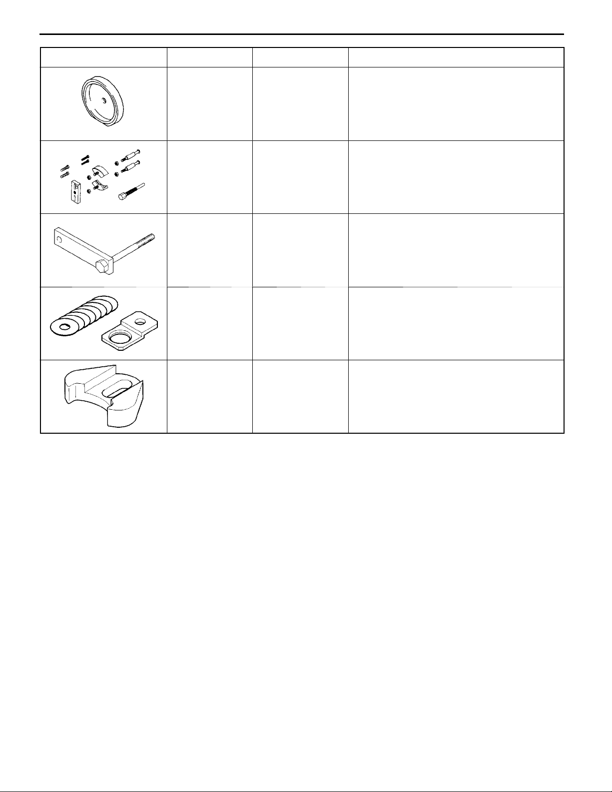
2. SPECIAL TOOLS
Tool Number Name Use
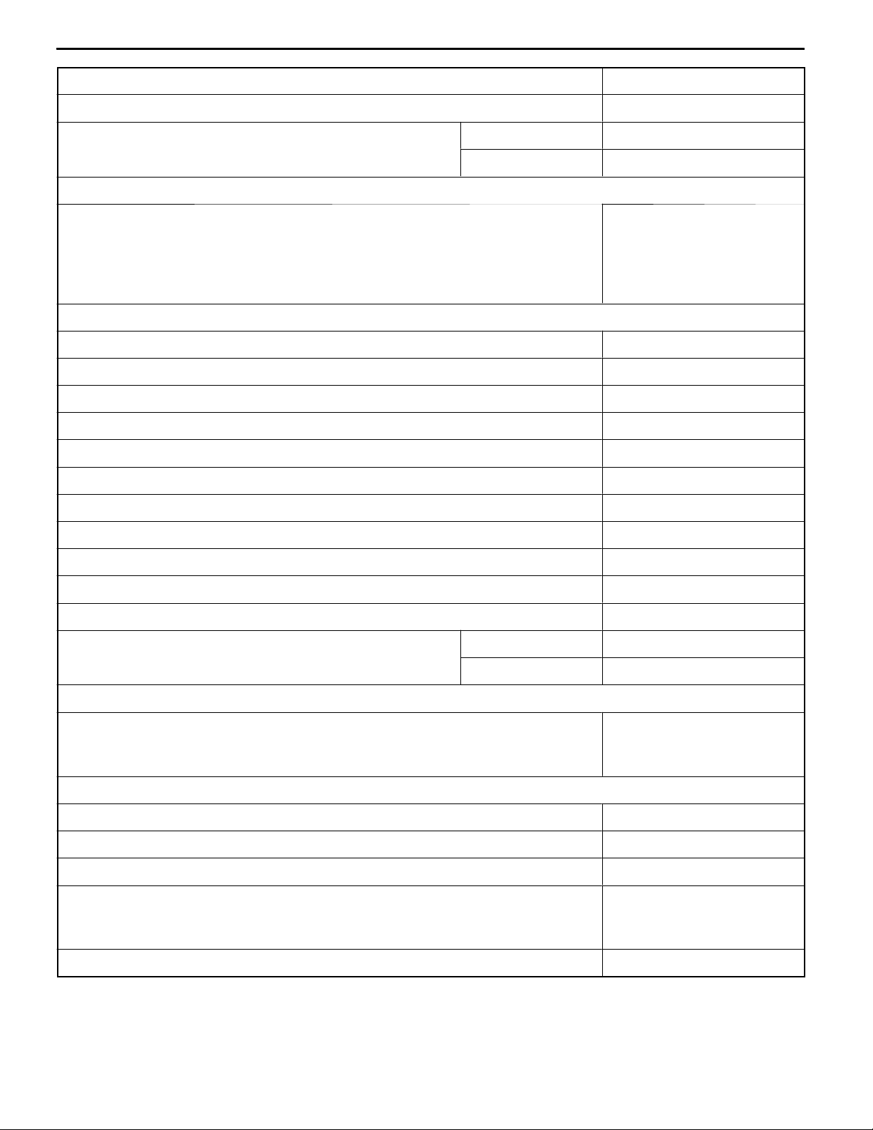
MB990767 End yoke holder Holding camshaft sprocket or fuel injection
11A-2-1
pump when loosening or tightening bolts.
Use with MD998719
MB991603 Bearing installer
stopper
MD990938 Handle Installation of crankshaft rear oil seal
MB991654 Cylinder head bolt
wrench
MD9981 15 Valve guide
installer
A guide for removal and installation of
counterbalance shaft left rear bearing
(Use with MD998776)
Tightening and loosening of cylinder head bolt
Removal and installation of valve guide
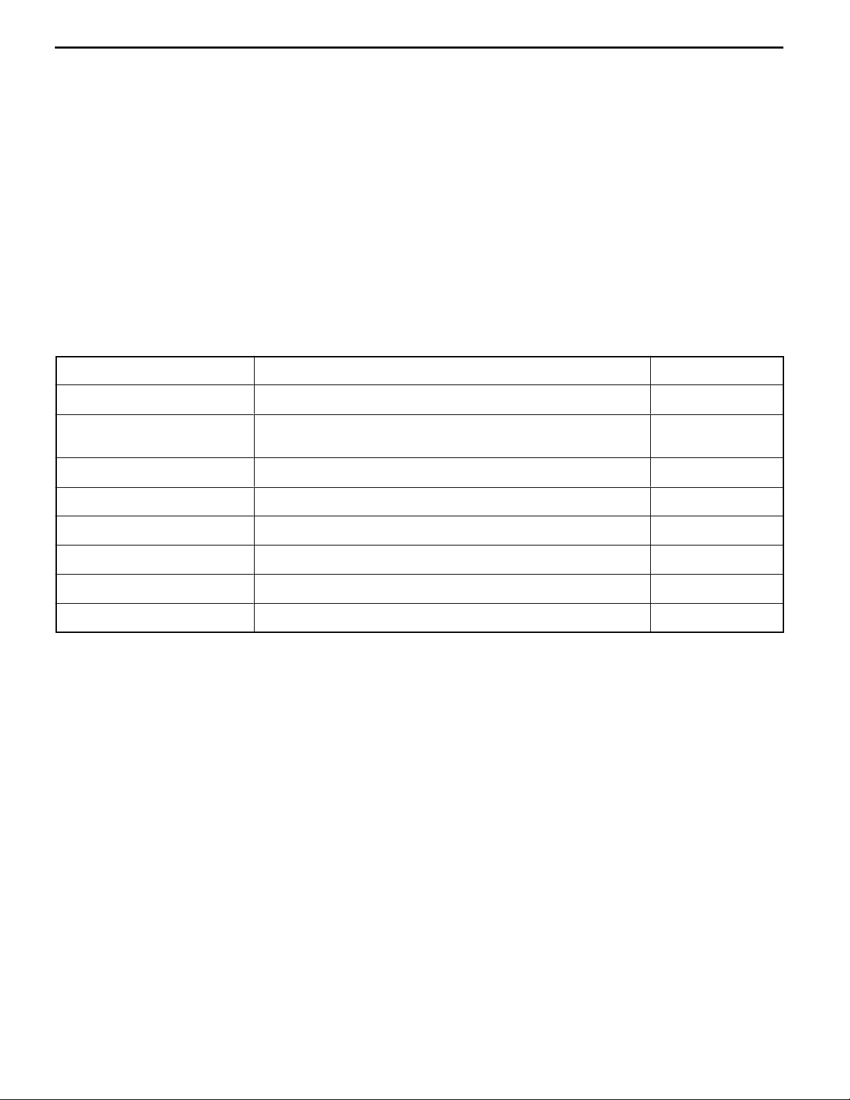
MD998162 Plug wrench Removal and installation of front case cap plug
(Use with MD998783)
MD998285 Crankshaft front oil
seal guide
MD998371 Silent shaft bearing
puller
MD998372 Silent shaft bearing
puller
Guide for installation of crankshaft front oil seal
Removal of counterbalance shaft front bearing
Removal of counterbalance shaft rear bearing
E
Dec. 1996Mitsubishi Motors Corporation
PWEE9609
Page 15
11A-2-2
Tool UseNameNumber
4D68 ENGINE (E-W) -
Special Tools
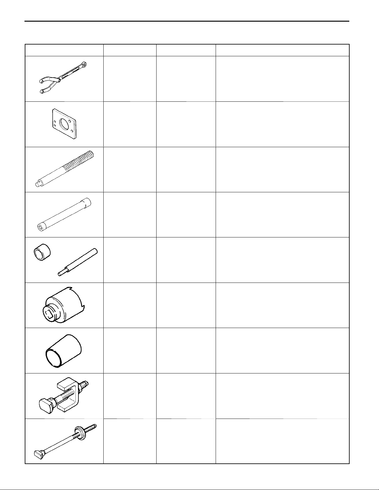
MD998375 Crankshaft front oil
seal installer
MD998388 Injection pump
sprocket puller
MD998702 Connecting-rod
small-end bushing
replacement tool
MD998705 Silent shaft bearing
installer
Installation of crankshaft front oil seal
Removal of injection pump sprocket
Replacement of connecting-rod small-end
bushing
Installation of counterbalance shaft bearing
MD998713 Camshaft oil seal
installer
MD998719 Pulley holder pin
(2)
MD998727 Oil pan sealer
cutter
MD998729 Valve stem seal
installer
Installation of camshaft oil seal
Use with MB990767
Removal of oil pan
Installation of valve stem seal
MD998772 Valve spring
compressor
E
Dec. 1996Mitsubishi Motors Corporation
PWEE9609
Compression of valve spring
Page 16
4D68 ENGINE (E-W) -
Tool UseNameNumber
Special Tools
11A-2-3
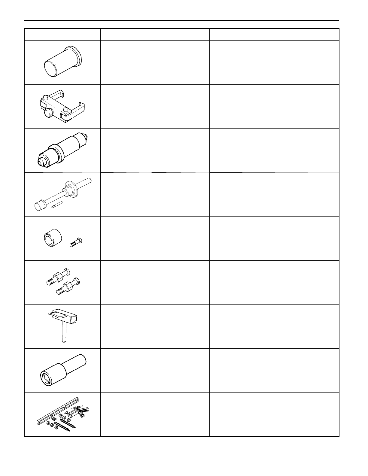
MD998776 Crankshaft rear oil
seal installer
MD998778 Crankshaft
sprocket puller
MD998781 Flywheel stopper Holding of flywheel and drive plate
MD998783 Plug wrench
retainer
Installation of crankshaft rear oil seal
(Use with MB990938)
Removal of crankshaft sprocket
Removal and installation of front case cap plug
(Use with MD998162)
MD998785 Sprocket stopper Holding of counterbalance shaft sprocket
E
Dec. 1996Mitsubishi Motors Corporation
PWEE9609
Page 17
4D68 ENGINE (E-W) -
Drive Belt and Glow Plug
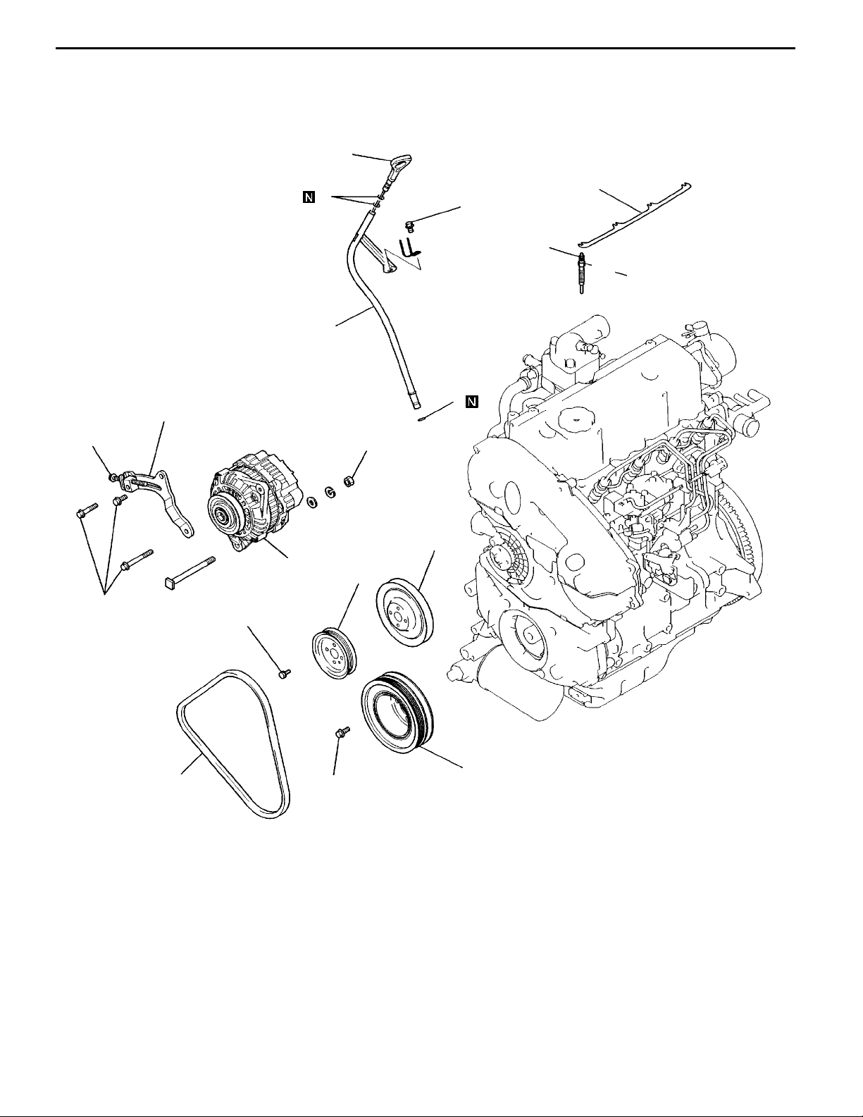
3. DRIVE BELT AND GLOW PLUG
REMOVAL AND INSTALLATION
1
11A-3-1
10 Nm
2
13 Nm
1.8 Nm
12
18 Nm
3
4
8
11
44 Nm
7
9
6
23 Nm
9Nm
5
Removal steps
1. Oil level gauge
2. O-ring
3. Oil level gauge guide
4. O-ring
5. Drive belt (V-type)
6. Pulley (for power steering pump
drive)
25 Nm
10
AA""AA
DEN0885
7. Water pump pulley
8. Alternator brace
9. Alternator
10. Crankshaft pulley
11. Glow plug plate
12. Glow plug
E
Dec. 1996Mitsubishi Motors Corporation
PWEE9609
Page 18
11A-3-2
4D68 ENGINE (E-W) -
REMOVAL SERVICE POINTS
AA"
(1) When removing the glow plug, you may loosen using
INSTALLATION SERVICE POINTS
"AA
(1) When installing the glow plug, screw in one thread or
Drive Belt and Glow Plug
GLOW PLUG REMOVAL
a tool up to the point where o n e or more threads are
left in engagement. Beyond this point, loosen with fingers.
Caution
D
Do not reuse a glow plug that has been dropped
from a height of 10 cm or more.
GLOW PLUG INSTALLATION
more with fingers and then tighten with a tool.
Caution
D
Do not reuse a glow plug that has been dropped
from a height of 10 cm or more.
DEL034
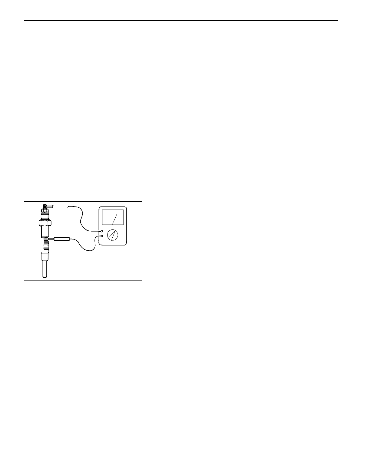
INSPECTION
GLOW PLUG
(1) Check the glow plugs for continuity between the terminal
and the body as shown. Replace the glow plugs which
show no continuity or too large a resistance.
Standard value: 0.5
W
E
Dec. 1996Mitsubishi Motors Corporation
PWEE9609
Page 19
4D68 ENGINE (E-W) -
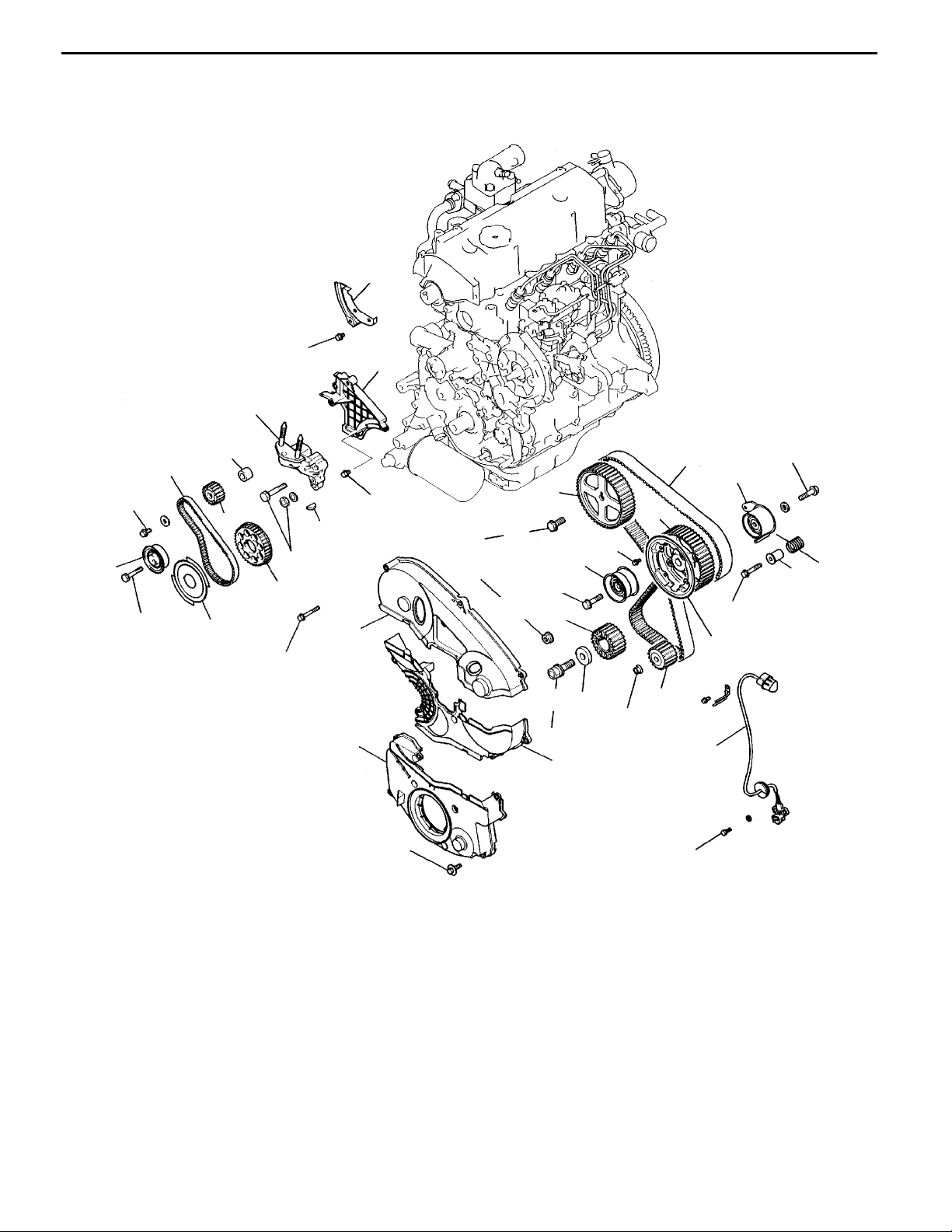
4. TIMING BELT
REMOVAL AND INSTALLATION
11 Nm
28
27
26
Timing Belt
11A-4-1
45 Nm
20
18 Nm
21
18
23
22
49 Nm
24
11 Nm
25
11 Nm
1
3
9Nm
88 Nm
83 Nm
10
48 Nm
13
11
9
17
15
16
118 Nm
2
9Nm
14
54 Nm
19
9Nm
5
12
4
6
13 Nm
48 Nm
8
7
DEN0886
AA""IA
"HA
AB""GA
AC""FA
AD"
E
Removal steps
1. Timing belt front upper cover
2. T iming belt front center cover
3. Timing belt front lower cover
4. Crankshaft position sensor
5. Timing belt
6. Timing belt tensioner
7. Tensioner spacer
8. Tensioner spring
9. Timing belt idler pulley
10. Camshaft sprocket bolt
11. Camshaft sprocket
12. Flange
13. Injection pump sprocket nut
14. Injection pump sprocket
Dec. 1996Mitsubishi Motors Corporation
PWEE9609
AE""EA
AF"
AG""DA
AH""CA
AI""BA
"AA
AJ"
15. Crankshaft bolt
16. Special washer
17. Crankshaft sprocket
18. Crankshaft sensing blade
19. Oil pump sprocket
20. Tensioner “B”
21. T iming belt “B”
22. Counterbalance shaft sprocket
23. Spacer
24. Crankshaft sprocket “B”
25. Key
26. T iming belt rear center cover
27. T iming belt rear right cover
28. Engine support bracket
Page 20
11A-4-2
4D68 ENGINE (E-W) -
REMOVAL SERVICE POINTS
AA"
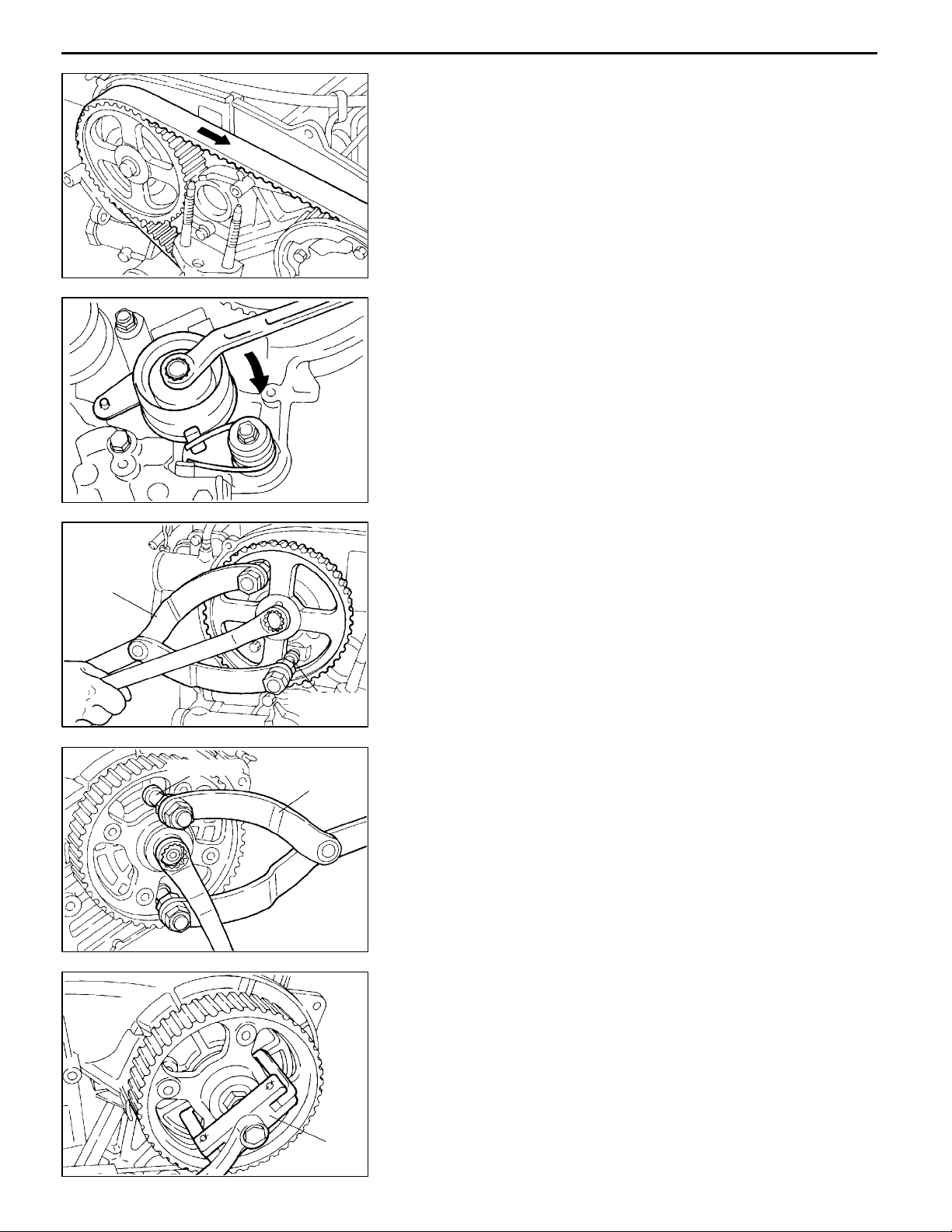
(1) Using chalk, etc., mark an arrow on the back of the timing
DEN0739
(2) Attach a bolt to the front end face of the timing belt
(3) Remove the timing belt.
DEN0838
TIMING BELT REMOVAL
belt to indicate the direction of rotation. This is to ensure
correct installation of the belt in case it is reused.
tensioner. Fit an offset wrench onto the bolt and turn the
wrench downward as shown to tighten the tensioner
mounting bolt temporarily.
Caution
D
Use such a short bolt as would not come into
contact with the timing belt tensioner mounting
bolt at the rear end face when it is tightened.
Timing Belt
MB990767
MB998719
MD998719
DEN0741
MB990767
DEN0742
AB"
AC"
AD"
CAMSHAFT SPROCKET BOLT LOOSENING
INJECTION PUMP SPROCKET NUT LOOSENING
INJECTION PUMP SPROCKET REMOVAL
(1) Do not strike the sprocket and drive shaft to remove these
parts.
MD998388
DFU0625
E
Dec. 1996Mitsubishi Motors Corporation
PWEE9609
Page 21
4D68 ENGINE (E-W) -
Timing Belt
11A-4-3
MD998781
Plug
DEN0743
MD998778
DEN0744
Screwdriver
6EN05646EN0563
AE"
AF"
AG"
CRANKSHAFT BOLT LOOSENING
CRANKSHAFT SPROCKET REMOVAL
OIL PUMP SPROCKET REMOVAL
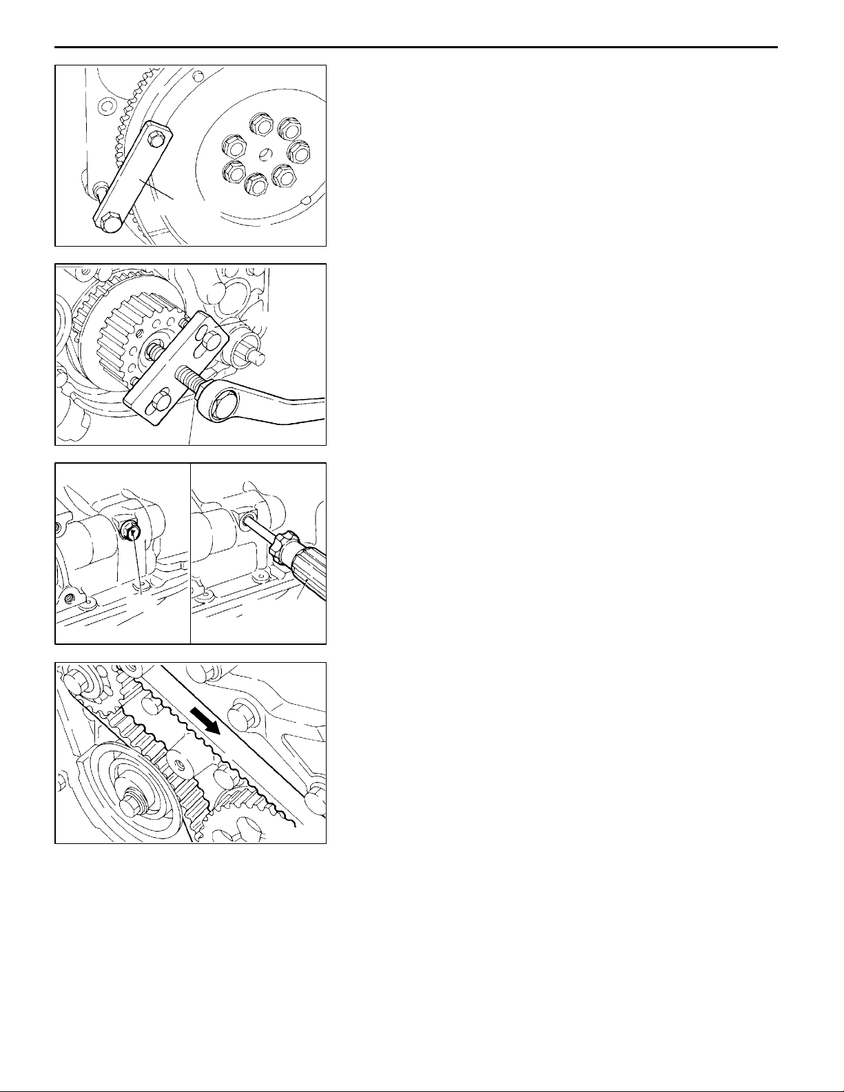
(1) Before loosening the oil pump sprocket nut (flange nut),
remove the timing belt and then the plug at the left side
of the cylinder block and insert a Phillips screwdriver [shank
diameter 8 mm] through the plug hole to keep the left
counterbalance shaft in position.
Caution
D
If the nut is loosened without removing the timing
belt, the force produced by loosening the nut will
be borne by the belt and can cause damage to
the belt cogs.
AH"
TIMING BELT “B” REMOVAL
(1) Using chalk, etc., mark an arrow on the back of the timing
belt to indicate the direction of rotation. This is to ensure
correct installation of the belt in case it is reused.
NOTE
(1) Water or oil on the belt shortens its life drastically,
so the removed timing belt, sprocket, an d tensioner
must be free from oil and water. Do not immerse parts
in cleaning solvent.
DEN0745
(2) If there is oil or water on any part, check the front
case oil seals, camshaft oil seal and water pump for
leaks.
E
Dec. 1996Mitsubishi Motors Corporation
PWEE9609
Page 22

11A-4-4
4D68 ENGINE (E-W) -
Timing Belt
MD998785
MD998778
DEN0746
DEN0747
AI"
AJ"
COUNTERBALANCE SHAFT SPROCKET
REMOVAL
CRANKSHAFT SPROCKET “B” REMOVAL
Spacer
Sharp
edge
Chamfer
Silent
shaft
MD998785
6EN0615
DEN0746
Timing
mark
Oil
seal
INSTALLATION SERVICE POINTS
"AA
(1) Install the spacer with the chamfered end toward t he oil
"BA
"CA
(1) Align the timing marks on the crankshaft sprocket “B”
(2) Install the timing belt “B” on the crankshaft sprocket “B”
SPACER INSTALLATION
seal.
COUNTERBALANCE SHAFT SPROCKET
INSTALLATION
TIMING BELT “B” INSTALLATION
and sprocket with the marks on the front case respectively.
and counterbalance shaft sprocket. There should be no
slack on the tension side.
Timing mark
E
DEN0839
Dec. 1996Mitsubishi Motors Corporation
PWEE9609
Page 23

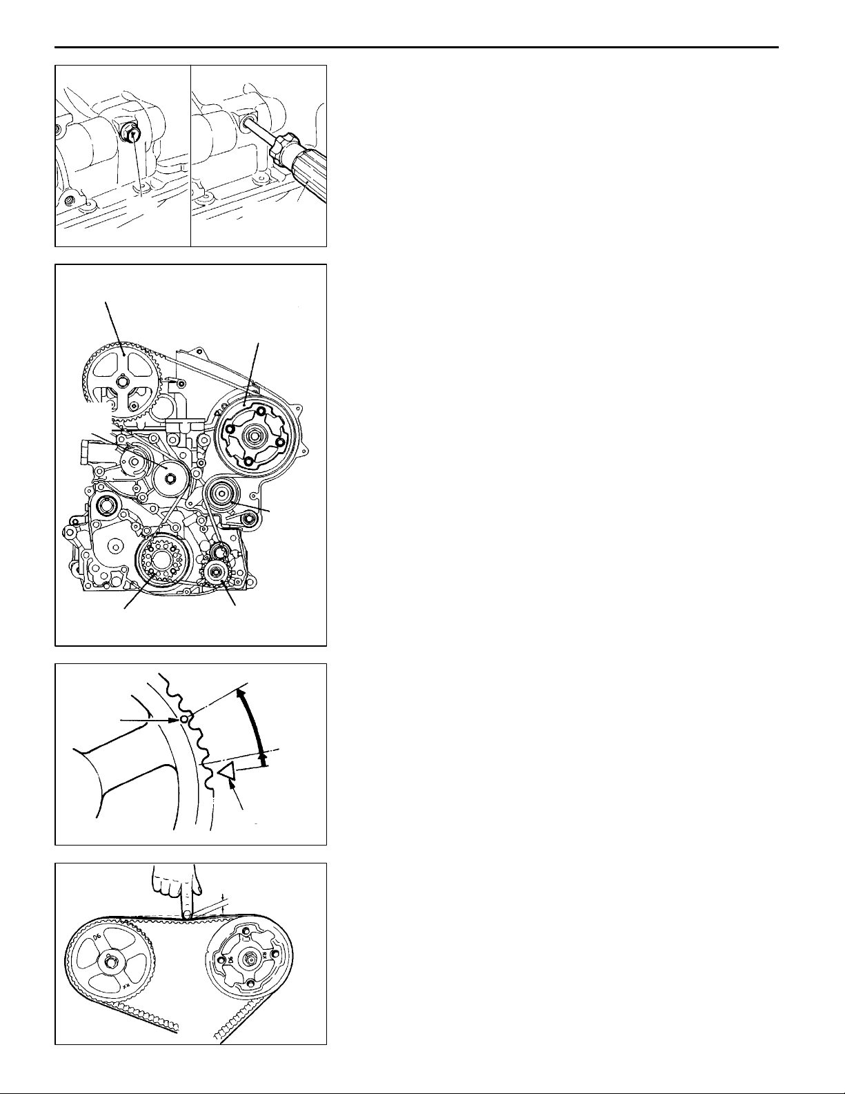
Tensioner “B”
Tensioner pulley
center
4D68 ENGINE (E-W) -
(3) Make sure that the pulley center and the bolt center are
Timing belt “B”
DEN0749
(4) More the tensioner “B” in the direction of arrow while lifting
Timing Belt
11A-4-5
located as shown in the illustration.
with a finger to give a sufficient tension to the tension
side of the timing belt. In this condition, tighten the bolt
to secure tensioner “B”. When the bolt is tightened, use
care to prevent the shaft from turning together. If the shaft
is turned together, the belt will b e overtensioned.
5-7mm
Phillips screwdriver
DEN0750
DEN0751
6EN0564
(5) Check to ensure that the timing marks on the sprockets
and the front case are in alignment.
(6) Press with index finger the center of span on the tension
side of timing belt “B”. The bolt must deflect 5 to 7 mm.
"DA
OIL PUMP SPROCKET INSTALLATION
(1) Keep the counterbalance shaft in position in the same
way as when it was loosened.
(2) Install the oil pump sprocket.
(3) Apply a minimum quantity of engine oil to the bearing
surface of the nut.
(4) Tighten the nuts to the specified torque.
"EA
MD998781
DEN0743
E
Dec. 1996Mitsubishi Motors Corporation
CRANKSHAFT BOLT TIGHTENING
PWEE9609
Page 24

11A-4-6
4D68 ENGINE (E-W) -
Timing Belt
MB990767
Camshaft
sprocket
Timing mark
Timing
mark
Oil pump sprocket
MD998719
MB990767
MD998719
Injection
pump
sprocket
DEN0754
DEN0755
DEN0838
"FA
"GA
"HA
INJECTION PUMP SPROCKET NUT TIGHTENING
CAMSHAFT SPROCKET BOLT TIGHTENING
TIMING BELT TENSIONER INSTALLATION
(1) Set the tensioner spring ends against the tensioner bracket
and the projection of the injection pump bracket.
(2) Attach a bolt to the front end face of the timing belt
tensioner. Fit an offset wrench onto the bolt and turn the
wrench downward as shown to tighten the tensioner
mounting bolt temporarily.
Caution
D
Use such a short bolt as would not come into
contact with the timing belt tensioner mounting
bolt at the rear end face when it is tightened.
"IA
TIMING BELT INSTALLATION
(1) Temporarily fix the tensioner at the most lower position
in the injection pump bracket slot.
(2) Turn the crankshaft to bring the No. 1 piston at the top
dead center on the compression stroke.
(3) Align the timing marks of all sprockets with their mating
marks as shown.
NOTE
If the injection pump sprocket is released, it turns about
one tooth in a counterclockwise direction. Therefore, the
timing mark of the injection pump sprocket should be
aligned when the timing belt is installed.
Timing mark
E
Camshaft
sprocket
Timing
mark
Dec. 1996Mitsubishi Motors Corporation
DEN0756
PWEE9609
Page 25
Plug
Camshaft sprocket
Timing
belt idler
4D68 ENGINE (E-W) -
(4) Remove the plug on the cylinder block and insert a Phillips
Screwdriver
6EN05646EN0563
(5) Install the timing belt on the sprockets in the following
Injection pump
sprocket
Timing Belt
11A-4-7
screwdriver [shank diameter 8 mm] through the hole.
If it can be inserted as deep as 60 mm or more, the timing
marks are correctly aligned. If the inserted depth is only
20 - 2 5 mm, turn the oil pump sprocket one turn and
realign the timing marks. Then check to ensure that the
screwdriver can be inserted 60 mm or more. Keep the
screwdriver inserted until installation of the timing belt
is finished.
sequence while taking care so that the belt is not slack
between sprockets or between sprocket and pulley.
1 Crankshaft sprocket
2 Timing belt idler
3 Camshaft sprocket
4 Injection pump sprocket
5 Oil pump sprocket
6 Turn the crankshaft in the reverse direction by 1/2
tooth of the camshaft sprocket to remove theslackenss
of the belt on the idler side.
7 Timing belt tensioner
Crankshaft sprocket
Timing
mark
Oil pump
sprocket
Timing mark
4-5mm
Timing
belt
tensioner
DEN0840
2-1/2
teeth
1/2 teeth
DEN0732
NOTE
To install the timing belt on the injection pump sprocket,
use an o ffset wrench or a similar tool and align the injection
pump sprocket timing mark with the mark in the engine.
(6) Loosen the tensioner mounting bolt 1/4 - 1/3 turn and
allow the spring tension to move the tensioner against
the belt.
(7) Turn the crankshaft counterclockwise by three teeth of
the cam sprocket from the timing mark and hold this
position. Check that the belt is in complete mesh with
the sprockets.
(8) Fix the tensioner.
(9) Turn the crankshaft clockwise to align t he timing marks.
(10)Check that the belt deflects 4 - 5 mm when its midpoint
is pushed by index finger.
(11)Check that the timing marks of all sprockets are aligned.
DEN0694
E
Dec. 1996Mitsubishi Motors Corporation
PWEE9609
Page 26

11A-4-8
4D68 ENGINE (E-W) -
INSPECTION
TIMING BELTS
The timing belts must be checked closely. Should the following
defects be evident, replace the belt with a new one.
(1) Hardened back surface rubber
Glossy, non-elastic, and so hard that no mark is produced
even when scratched by fingernails.
8EN0066
Timing Belt
Separation
Tooth bottom
Crack
Rounded edge
Abnormal wear
(loose core wire)
Canvas worn
exposing rubber
Stripped
teeth
Crack
Cracked
side
8EN0044
8EN0067
(2) Cracked back surface rubber
(3) Cracked or separated canvas
(4) Cracked tooth bottom
(5) Cracked side
(6) Abnormal wear on side
NOTE
Normal belt should have clear-cut sides as if cut by a
sharp knife.
(7) Abnormal wear in teeth
Initial stage:
Canvas on load side tooth flank worn (Fluffy canvas
fibers, rubber gone and color changed to white, and
unclear canvas texture)
Final stage:
Canvas on load side tooth flank worn down and rubber
exposed (tooth width reduced)
(8) Missing tooth
8EN0068
TENSIONER PULLER, IDLER PULLEY
(1) Check the pulley for smooth rotation, excessive play,
abnormal noise. Replace it if necessary.
DEN0911
E
Dec. 1996Mitsubishi Motors Corporation
PWEE9609
Page 27

4D68 ENGINE (E-W) -
Glow Plug, Fuel Injection Pump And Injection Nozzle
5. GLOW PLUG, FUEL INJECTION PUMP AND INJECTION NOZZLE
REMOVAL AND INSTALLATION
5Nm
5Nm
1
3
11A-5-1
4
19
10
11
29 Nm
54 Nm
17
18
16
29 Nm
13
2
29 Nm
14
15
5
18 Nm
9
6
13 Nm
7
23 Nm
18 Nm
8
13 Nm
AA""DA
AA""DA
AA""DA
AA""DA
AB"
E
23 Nm
Removal steps
1. Injection pipe No.1
2. Injection pipe No.2
3. Injection pipe No.3
4. Injection pipe No.4
5. Fuel hose
6. Fuel hose
7. Fuel hose
8. Fuel pipe
9. Engine hanger
10. Fuel injection pump
Dec. 1996Mitsubishi Motors Corporation
12
PWEE9609
AC""CA
AD""BA
"AA
"AA
35 Nm
DEN0887
11. Key
12. Fuel injection pump stay
13. Fuel return pipe nut
14. Fuel return pipe
15. Fuel return pipe gasket
16. Injection nozzle
17. Holder gasket
18. Nozzle gasket
19. Fuel injection pump bracket
Page 28

11A-5-2
4D68 ENGINE (E-W) -
Glow Plug, Fuel Injection Pump And Injection Nozzle
Delivery
holder
Nut
DEN0759
REMOVAL SERVICE POINTS
AA"
(1) When loosening the union nuts on the injection pump,
(2) When loosening the union nuts on the injection nozzles,
AB"
(1) Do not hold the injection pump by the accelerator lever
INJECTION PIPE REMOVAL
hold the delivery valve holder on the fuel injection pump
head with a spanner to prevent it from rotating along with
the union nut.
Caution
D
If the injection pipe has been removed, plug the
delivery valve holder to prevent foreign matter
from entering the injection pump.
hold the hexagon nut of the fuel return pipe with a spanner
to prevent it from rotating along with the union nut.
FUEL INJECTION PUMP REMOVAL
or the fast idle lever. These levers must not be removed.
DEN0760
AC"
FUEL RETURN PIPE NUT REMOVAL
(1) When removing the fuel return pipe nut, hold the hexagon
nut of the fuel return pipe with a spanner.
DEN0761
Deep socket wrench
AD"
(1) Write the cylinder number on the injection nozzle that
INJECTION NOZZLE REMOVAL
has been removed.
Caution
D
Cover the opening with an appropriate cap to
prevent entry of dust, water and foreign material
into the fuel passage and combustion chamber.
DEN0762
E
Dec. 1996Mitsubishi Motors Corporation
PWEE9609
Page 29

4D68 ENGINE (E-W) -
Holder gasket
Nozzle
gasket
DFU616
Glow Plug, Fuel Injection Pump And Injection Nozzle
11A-5-3
INSTALLATION SERVICE POINTS
"AA
(1) Clean nozzle holder installation areas of the cylinder head.
(2) Fit a new nozzle gasket and holder gasket into the nozzle
NOZZLE GASKET / HOLDER GASKET
INSTALLATION
holder hole in the cylinder head.
Deep socket wrench
Delivery
valve holder
Nut
DEN0763
DEN0761
"BA
"CA
INJECTION NOZZLE INSTALLATION
FUEL RETURN PIPE NUT INSTALLATION
(1) While holding the fuel hexagon nut of the fuel return pipe
with a wrench, tighten the fuel return pipe nut to the
specified torque.
"DA
INJECTION PIPE INSTALLATION
(1) When tightening the injection pipe nuts, hold the delivery
valve holder with a spanner in order to prevent it from
rotating along with the nut.
DEN0759
(2) When tightening the injection pipe nuts, hold the hexagon
nut of the return pipe with a spanner in order to prevent
it from rotating along with the nut.
DEN0760
E
Dec. 1996Mitsubishi Motors Corporation
PWEE9609
Page 30

4D68 ENGINE (E-W) -
Intake and Exhaust Manifolds
6. INTAKE AND EXHAUST MANIFOLDS
REMOVAL AND INSTALLATION
11A-6-1
17 Nm
13 Nm
14 Nm
11 Nm
13 Nm
34
30 Nm
59 Nm
29 Nm
11 Nm
14
35
13
12
16
27
15
36
28
59 Nm
17 Nm
16 Nm
10 Nm
17
19
59 Nm
33
59 Nm
9Nm
18
25
9
22
32
24
26
24 Nm
11
23
30
10
16 Nm
20
21
30 Nm
10 Nm
7
8
17 Nm
3
1
4
2
14 Nm
5
6
38
39
"CA
"BA
"BA
23 Nm
37
13 Nm
31
13 Nm
Removal steps
1. Air temperature sensor
2. Air temperature sensor gasket
3. Air intake fitting
4. Intake fitting gasket
5. Throttle body
6. Intake fitting gasket
7. EGR valve
8. EGR valve gasket
9. EGR pipe gasket
10. EGR pipe
11. EGR pipe gasket
12. T urbocharger heat protector
13. Exhaust fitting heat protector
14. Eyebolt
15. Gasket
16. W ater pipe “A”
17. W ater hose
18. Eyebolt
19. Gasket
20. Eyebolt
30
29
"AA
DEN0888
21. Gasket
22. Oil pipe
23. Eyebolt
24. Gasket
25. W ater pipe “B”
26. W ater hose
27. Exhaust fitting
28. Exhaust fitting gasket
29. Oil return pipe
30. Oil return pipe gasket
31. Heat protector, rear
32. T urbocharger assembly
33. T urbocharger gasket
34. Heat protector, front
35. Engine hanger
36. Exhaust manifold
37. Alternator brace stay
38. Intake manifold
39. Intake and exhaust manifold gasket
E
Dec. 1996Mitsubishi Motors Corporation
PWEE9609
Page 31

11A-6-2
Projection
4D68 ENGINE (E-W) -
Oil return pipe
DEN0843
Intake and Exhaust Manifolds
INSTALLATION SERVICE POINTS
"AA
(1) Install the oil return pipe gasket in such a way that its
OIL RETURN PIPE GASKET INSTALLATION
projection is located at the illustrated position.
Exhaust fitting
EGR pipe
Exhaust fitting
heat protector
Projection
DEN0844
"BA
EYEBOLT INSTALLATION
(1) Before installing the oil pipe eyebolt (at top of the
turbocharger), fill the turbocharger with clean engine oil.
"CA
EGR PIPE GASKET INSTALLATION
(1) Install the EGR pipe gasket in such a way that its projection
is located at the illustrated position.
E
Dec. 1996Mitsubishi Motors Corporation
PWEE9609
Page 32

4D68 ENGINE (E-W) -
Water Pump, Thermostat, Hose and Pipes
7. WATER PUMP, THERMOSTAT, HOSE AND PIPES
REMOVAL AND INSTALLATION
16 Nm
1
2
17
3
11A-7-1
15
14
12 Nm
45 Nm
16
4
9Nm
5
18
22 Nm
8
23 Nm
19
7
11 Nm
6
10
23 Nm
22
9
35 Nm
20
12 Nm
21
11
12
19 Nm
13
13 Nm
Removal steps
1. Eyebolt
2. Gasket
3. Oil pipe
4. Gasket
5. Eyebolt
6. Gasket
7. Oil return pipe
8. Oil return hose
"FA
"EA
E
9. Engine coolant temperature sensor
10. Engine coolant temperature gauge
unit
11. Cover
Dec. 1996Mitsubishi Motors Corporation
PWEE9609
"DA
"DA
"DA
"CA
"BA
"AA
12. W ater pump
13. Water pump gasket
14. O-ring
15. Water inlet pipe
16. O-ring
17. Vacuum pump
18. O-ring
19. Water inlet fitting
20. Thermostat
21. Water outlet fitting
22. Thermostat housing
DEN0889
Page 33

11A-7-2
4D68 ENGINE (E-W) -
DEN0768
Water Pump, Thermostat, Hose and Pipes
INSTALLATION SERVICE POINTS
"AA
(1) Apply a 3 mm bead of form-in-place gasket (FIPG) to
THERMOSTAT HOUSING INSTALLATION
the mounting surface.
Specified sealant:
Mitsubishi Genuine Part No. MD970389 or
equivalent.
DEN0769
Jiggle valve
DEN0770
"BA
WATER OUTLET FITTING INSTALLATION
(1) Apply a 3 mm bead of form-in-place gasket (FIPG) to
the mounting surface.
Specified sealant:
Mitsubishi Genuine Part No. MD970389 or
equivalent.
"CA
THERMOSTAT INSTALLATION
(1) Install th e thermostat with t h e jiggle valve up as shown
in the illustration.
"DA
WATER INLET PIPE / O-RING INSTALLATION
(1) Wet the O-ring (with water) to facilitate assembly.
Caution
D
Keep the O-ring free of oil or grease.
D
Secure the water pipe after the thermostat housing
has been installed.
Back side of cover
E
"EA
COVER INSTALLATION
(1) Apply a 3 mm bead of form-in-place gasket (FIPG) to
the mounting surface.
Specified sealant:
Mitsubishi Genuine Part No. MD970389 or
equivalent.
DEN0846
Dec. 1996Mitsubishi Motors Corporation
PWEE9609
Page 34

4D68 ENGINE (E-W) -
Water Pump, Thermostat, Hose and Pipes
11A-7-3
DEN0890
"FA
ENGINE COOLANT TEMPERATURE GAUGE UNIT
INSTALLATION
(1) If the water temperature sensor is to be reused, apply
the specified sealant to its thread.
Specified sealant:
3M Nut Locking Part No. 4171 or equivalent.
E
Dec. 1996Mitsubishi Motors Corporation
PWEE9609
Page 35

4D68 ENGINE (E-W) -
Rocker Arms, Rocker Shaft and Camshaft
8. ROCKER ARMS, ROCKER SHAFT AND CAMSHAFT
REMOVAL AND INSTALLATION
6Nm
29 Nm
7
15 Nm
20 Nm
29 Nm
12
8
12
5
4
6
12
20 Nm
29 Nm
2
11
11A-8-1
1
10
9
12
Removal steps
1. Breather hose
2. Rocker cover
3. Rocker cover gasket
4. Rocker shaft
5. Rocker shaft spring
6. Rocker arm
7. Adjusting nut
8. Rocker arm adjusting screw
9. Front camshaft bearing cap
10. Camshaft front oil seal
11. Rear camshaft bearing cap
12. Camshaft bearing cap
13. Camshaft
13
"AA
"BA
"BA
"CA
"DA
"EA
3
Apply engine oil to all
moving parts before
installation.
DEN0891
Installation steps
13. Camshaft
12. Camshaft bearing cap
11. Rear camshaft bearing cap
9. Front camshaft bearing cap
8. Rocker arm adjusting screw
7. Nut
6. Rocker arm
5. Rocker shaft spring
4. Rocker shaft
10. Camshaft oil seal
3. Rocker cover gasket
2. Rocker cover
1. Breather hose
E
Dec. 1996Mitsubishi Motors Corporation
PWEE9609
Page 36

11A-8-2
4D68 ENGINE (E-W) -
Rocker Arms, Rocker Shaft and Camshaft
Camshaft
sprocket side
Identification
number
Front
DEN658
DEN0905
Within 1 mm
INSTALLATION SERVICE POINTS
"AA
(1) Install the bearing caps in the designated position
"BA
(1) Apply sealant to the locations shown in the illustrations.
"CA
(1) Do not screw the adjusting screw so far that its flange
CAMSHAFT BEARING CAP INSTALLATION
confirming the identification numbers stamped o n the cap
front. The No.5 cap has no identification number stamped.
FRONT, REAR CAMSHAFT BEARING CAP
INSTALLATION
Specified sealant:
3M ATD Part No. 8660 or equivalent
ROCKER ARM ADJUSTING SCREW
INSTALLATION
may come into contact with the rocker arm. Leave some
distance (within 1 mm) between them.
Depression
Bearing cap
E
MD998713
Dec. 1996Mitsubishi Motors Corporation
DEN0848
DEN0803
DEN0773
"DA
ROCKER SHAFT SPRING INSTALLATION
(1) Hook the rocker shaft spring to the depression of the
bearing cap.
"EA
CAMSHAFT OIL SEAL INSTALLATION
(1) Using the special tool, install a new camshaft oil seal
into the front bearing cap.
PWEE9609
Page 37

Camshaft
sprocket
4D68 ENGINE (E-W) -
Timing mark
DEN0605
Rocker Arms, Rocker Shaft and Camshaft
11A-8-3
VALVE CLEARANCE ADJUSTMENT
(1) Turn the crankshaft clockwise an d align the timing mark
on camshaft sprocket with that on the injection pump
bracket.
(2) Adjust the valve clearance at the points shown in the
illustration.
Exhaust
No.1
Intake
No.1
Intake
No.2
Exhaust
No.3
DEN0774
DEN0775
Adjusting
screw
Pad
(3) Loosen the adjusting screw lock nut.
(4) Using a thickness gauge, adjust the valve clearance by
turning the adjusting screw.
Standard value (on cold engine):
Intake 0.25 mm
Exhaust 0.35 mm
NOTE
Before insertion of a thickness gauge, provide clearance
for inserting the gauge by pushing the pad with a standard
screwdriver or the like from the opposite side.
Standard screwdriver
or the like
Pad
E
Thickness
gauge
Thickness
gauge
Dec. 1996Mitsubishi Motors Corporation
DEN0718
If an attempt is made to insert the thickness gauge without
providing the clearance for it in advance by pushing the
pad with a standard screwdriver or the like, the pad will
tilt as shown in the illustration, preventing insertion of the
thickness gauge.
DEN0719
PWEE9609
Page 38

11A-8-4
4D68 ENGINE (E-W) -
Exhaust
No.2
Intake
No.3
Exhaust
No.4
Intake
No.4
DEN0776
Rocker Arms, Rocker Shaft and Camshaft
(5) While holding the adjusting screw with a screwdriver,
tighten the lock nut.
(6) Rotate clockwise the crankshaft one complete turn (360
degrees).
(7) Adjust the valve clearance at the points shown in the
illustration.
(8) Repeat steps (3) to (5) to adjust the valve clearance of
the remaining valves.
NOTE
With the engine mounted on vehicle, warm up the engine.
Then, check for valve clearance on hot engine and adjust
if necessary.
9EN0058
INSPECTION
CAMSHAFT
(1) Measure the cam height.
Standard value:
Intake 41.90 mm
Exhaust 41.96 mm
Limit:
Intake 41.40 mm
Exhaust 41.46 mm
ROCKER ARM SHAFT
(1) Check the oil holes for clogging and clean if clogged.
(2) Check the outer circumference of the portion where the
rocker arm is installed and replace if damage or seizure
is evident.
E
Dec. 1996Mitsubishi Motors Corporation
PWEE9609
Page 39

4D68 ENGINE (E-W) -
Cylinder Head, Valves and Valve Springs
9. CYLINDER HEAD, VALVES AND VALVE SPRINGS
REMOVAL AND INSTALLATION
11A-9-1
AA""EA
"DA
AB""CA
"BA
E
Removal steps
1. Cylinder head bolt
2. Cylinder head assembly
3. Cylinder head gasket
4. Valve spring retainer lock
5. Valve spring retainer
6. Valve spring
7. Intake valve
8. Exhaust valve
Dec. 1996Mitsubishi Motors Corporation
PWEE9609
AC""AA
Apply engine oil to all
moving parts before
installation.
DEN0777
9. Valve stem seal
10. Spring seat
11. Intake valve guide
12. Exhaust valve guide
13. Intake valve seat
14. Exhaust valve seat
15. Cylinder head
Page 40

11A-9-2
4D68 ENGINE (E-W) -
MB991654
DEN0778
Cylinder Head, Valves and Valve Springs
REMOVAL SERVICE POINTS
AA"
(1) Using a 12 mm - 12 points socket wrench, loosen the
CYLINDER HEAD BOLT REMOVAL
cylinder head bolts.
MD998772
DEN0779
DEN0793
AB"
RETAINER LOCK REMOVAL
(1) Store removed valves, springs and other parts, tagged
to indicate their cylinder No. and location for reassembly.
AC"
VALVE STEM SEAL REMOVAL
(1) Do not reuse removed stem seals.
E
Painted
end
MD998729
DEN0780
Spring retainer
Stem seal
Spring seat
6EN0437
Dec. 1996Mitsubishi Motors Corporation
INSTALLATION SERVICE POINTS
"AA
(1) Install the valve spring seat.
(2) The special tool must be used to install valve stem seals.
"BA
(1) Direct the valve spring end with identification color toward
VALVE STEM SEAL INSTALLATION
Improper installation could result in oil leaks past the valve
guide.
Caution
D
Do not reuse removed valve stem seals.
VALVE SPRING INSTALLATION
the spring retainer.
PWEE9609
Page 41

4D68 ENGINE (E-W) -
Cylinder Head, Valves and Valve Springs
11A-9-3
MD998772
Identification mark
Rank A Rank B Rank C
12345678
Reference for measurement
Protrusion measuring locations
(with each piston at top dead center)
Protrusion
DEN0779
DEN0796
DEN0797
DEN0798
"CA
RETAINER LOCK INSTALLATION
(1) The valve spring, if excessively compressed, causes the
bottom end of the retainer to be in contact with, a n d
damage, the stem seal.
"DA
CYLINDER HEAD GASKET INSTALLATION
(1) In case any of the cylinder block, piston, connecting rod
and crankshaft has not been replaced, install the gasket
of the same rank as before which can be identified by
the mark shown in the illustration a t left.
(2) In case any of the cylinder block, piston, connecting rod
and crankshaft have been replaced, reselect and install
the gasket in accordance with the following procedure.
1 With each piston held at the top dead center, measure
its protrusion from the upper block surface at the
locations shown in the illustration at left (total of eight
locations). Be sure to take measurements on the
crankshaft center line.
2 Using the average of the eight measurements, select
the gasket rank (A, B or C) in accordance with the
table given below. If, however, the maximum protrusion
at any one location exceeds the protrusion tolerance
shown for any rank in the following table, use the
gasket one rank higher that rank.
mm
Rank
A 0.641 - 0.700 0.750 1.40±0.05
B 0.700 - 0.760 0.810 1.45±0.05
C 0.760 - 0.823 - 1.50±0.05
Average value
of piston
protrusions
Protrusion
tolerance for
each rank
Thickness of
selected gasket
(when tightened)
"EA
CYLINDER HEAD BOLT INSTALLATION
(1) When installing the cylinder head bolts, check that the
shank length of each bolt meets t h e limit. If the limit is
exceeded, replace the bolt.
Limit: max. 119.7 mm
(2) Apply engine oil to the bolt threads and washers.
Shank length
6EN0782
E
Dec. 1996Mitsubishi Motors Corporation
PWEE9609
Page 42

11A-9-4
4D68 ENGINE (E-W) -
Timing belt side
DEN0781
90
°
90
°
Paint mark
6AE0297
Cylinder Head, Valves and Valve Springs
(3) Using the special tool (MB991654) and according to the
tightening sequence, tighten the bolts to the specified
torque.
Tightening torque: 90 Nm
(4) Loosen all bolts fully.
(5) Retighten the loosened bolts to a torque of 40 Nm in
the specified tightening sequence.
(6) Make paint marks on the cylinder head bolt heads and
cylinder head.
(7) Give a 90° turn to the cylinder head bolts in the specified
tightening sequence.
(8) Give another 90° turn to the cylinder head bolts and make
sure that the paint mark on the head of each cylinder
head bolt and that on the cylinder head are on the same
straight line.
Caution
D
If the bolt is turned less than 90°, proper fastening
performance may not be expected. When
tightening the bolt, therefore, be careful to give
a sufficient turn to it.
D
If the bolt is overtightened, loosen the bolt
completely and then retighten it by repeating the
tightening procedure from step (1).
INSPECTION
CYLINDER HEAD
(1) Before cleaning the cylinder head, check it for water leaks,
gas leaks, cracks, and other damage.
(2) Remove all oil, water scale, sealant, and carbon. After
cleaning the oil passages, blow air through them to verify
that they are not blocked.
(3) Check for distortion in the cylinder head gasket surface
using a straight edge and thickness gauge. If distortion
DEN0794
E
Dec. 1996Mitsubishi Motors Corporation
exceeds the specified limit, replace the cylinder head.
Gasket surface distortion
Standard value: 0.05 mm or less
Limit: 0.2 mm
PWEE9609
Page 43

Valve seat
contact
4D68 ENGINE (E-W) -
Margin
6EN0542
Cylinder Head, Valves and Valve Springs
11A-9-5
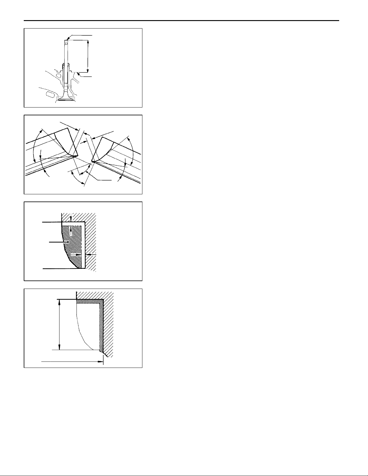
VALVE
(1) Check the valve face for correct contact. If incorrect, reface
using a valve refacer. Valve seat contact should be
maintained uniform at the center of valve face.
(2) If the margin is smaller than the service limit, replace
the valve.
Standard value: 1.5 mm
Limit: 0.7 mm
(3) Measure the overall height of the valve. If the specified
limit is exceeded, replace the valve.
Standard value:
Intake 114.05 mm
Exhaust 113.80 mm
Limit:
Intake 113.55 mm
Exhaust 113.30 mm
Guide I.D.
Stem O.D.
Free
height
1EN0264
6EN0279
VALVE SPRING
(1) Measure the free height of the spring and, if it is smaller
than the limit, replace.
Standard value: 49.1 mm
Limit: 48.1 mm
(2) Measure the squareness of the spring and, if the limit
is exceeded, replace.
Standard value: 2°or less
Limit: Max. 4
°
VALVE GUIDE
(1) Measure the clearance between the valve guide and valve
stem. If the limit is exceeded, replace the valve guide
or valve, or both.
Standard value: 0.05 - 0.09 mm
Limit: 0.15 mm
VALVE SEAT
(1) Check the valve seat for trace of overheat and contact
with valve surface.
Standard value: 0.9 - 1.3 mm
Valve contact
width
1EN033
E
Dec. 1996Mitsubishi Motors Corporation
PWEE9609
Page 44
11A-9-6
4D68 ENGINE (E-W) -
Cylinder Head, Valves and Valve Springs
0.9 - 1.3 mm
65
°
15
°
44
Valve stem end
(2) Install the valve and, while pressing the valve against
the valve seat, measure the valve stem projection between
the valve stem end and the valve spring seat seating
Valve stem
projection
surface.
Standard value: 43.45 mm
Limit: 43.95 mm
Spring seat seating
surface
DEN0212
VALVE SEAT RECONDITIONING PROCEDURE
0.9 - 1.3 mm
65
°
44
°
°
15
°
1EN0105
(1) Before correcting the valve seat, check the clearance
between the valve guide and valve. If necessary, replace
the valve guide.
(2) Using the appropriate special tool or seat grinder, correct
the valve seat to achieve the specified seat width and
angle.
(3) After correcting the valve seat, lap the valve and valve
seat using lapping compound. Then, check the valve stem
projection (refer to 5. VALVE SEAT in INSPECTION).
Cut
away
Height of
seat ring
0.5 - 1.0 mm
Oversize I.D.
0.5 - 1.0 mm
1EN0274
1EN0275
VALVE SEAT REPLACEMENT PROCEDURE
(1) Cut the valve seat to be replaced from the inside to thin
the wall thickness. Then, remove t h e valve seat.
(2) Rebore the valve seat hole in the cylinder head to a selected
oversize valve seat diameter.
Intake valve seat hole diameter
0.30 O.S.: 38.300 - 38.325 mm
0.60 O.S.: 38.600 - 38.625 mm
Exhaust valve seat hole diameter
0.30 O.S.: 34.300 - 34.325 mm
0.60 O.S.: 34.600 - 34.625 mm
(3) Before fitting the valve seat, either heat the cylinder head
up to approximately 250°C or cool the valve seat using
cooling spray, to prevent the cylinder head bore from
galling.
(4) Using a valve seat cutter, correct the valve seat to the
specified width and angle.
See “VALVE SEAT RECONDITIONING PROCEDURE”.
E
Dec. 1996Mitsubishi Motors Corporation
PWEE9609
Page 45

4D68 ENGINE (E-W) -
Cylinder Head, Valves and Valve Springs
11A-9-7
Removal
Installation
Press
Press
Push rod
contained in
MD998115
Valve guide
MD998115
Valve guide
6EN0543
6EN0543
VALVE GUIDE REPLACEMENT PROCEDURE
(1) Using the special tool and a press, remove the valve guide
toward the cylinder head gasket surface.
(2) Rebore the valve guide hole to the new oversize valve
guide outside diameter.
Valve guide hole diameter
0.05 O.S.: 13.050 - 13.068 mm
0.25 O.S.: 13.250 - 13.268 mm
0.50 O.S.: 13.500 - 13.518 mm
NOTE
Do not install a valve guide of the same size again.
(3) Using the special tool, press-fit the valve guide, working
from the cylinder head top surface.
(4) After installing valve guides, insert new valves in them
to check for sliding condition.
(5) When valve guides have been replaced, check for valve
contact and correct valve seats as necessary.
E
Dec. 1996Mitsubishi Motors Corporation
PWEE9609
Page 46

4D68 ENGINE (E-W) -
Front Case, Counterbalance Shafts and Oil Pan
11A-10-1
10. FRONT CASE, COUNTERBALANCE SHAFTS AND OIL PAN
REMOVAL AND INSTALLATION
30
29
Apply engine oil to all
moving parts before
installation.
20
27
31
54 Nm
18 Nm
10 Nm
8
14
24 Nm
28
21
19
25
9
15
24
22
23
10 Nm
16 Nm
9Nm
17
26
16
18
23 Nm
36 Nm
24 Nm
5
13
11
12
6
19 Nm
4
7
10
44 Nm
39 Nm
2
3
7Nm
1
DEN0892
AA""LA
"KA
AB""JA
E
Removal steps
1. Oil filter
2. Drain plug
3. Drain plug gasket
4. Oil level sensor
5. Oil pan
6. Oil screen
7. Oil screen gasket
8. Oil cooler bypass valve
9. Oil pressure switch
10. Relief plug
11. Gasket
12. Relief spring
13. Relief plunger
14. Oil filter bracket
15. Oil filter bracket gasket
16. Plug
17. O-ring
Dec. 1996Mitsubishi Motors Corporation
PWEE9609
AC""IA
"HA
"GA
"GA
"FA
"EA
"DA
AD""CA
AE""BA
AE""AA
18. Flange bolt
19. Front case
20. Front case gasket
21. Oil pump cover
22. Oil pump driven gear
23. Oil pump drive gear
24. Crankshaft front oil seal
25. Counterbalance shaft oil seal
26. Oil pump oil seal
27. Counterbalance shaft, right
28. Counterbalance shaft, left
29. Counterbalance shaft front bearing
30. Counterbalance shaft rear bearing,
right
31. Counterbalance shaft rear bearing,
left
Page 47

11A-10-2
MD998727
4D68 ENGINE (E-W) -
6EN0698
Front Case, Counterbalance Shafts and Oil Pan
REMOVAL SERVICE POINTS
AA"
(1) Knock the special tool deeply between the oil pan and
(2) Hitting the side of the special tool, slide the special tool
OIL PAN REMOVAL
the cylinder block.
along the oil pan to remove it.
Plug
MD998162
MD998783
6EN0909
Screwdriver
6EN05646EN0563
AB"
PLUG REMOVAL
(1) If the plug is too hard to loosen, tap on the plug several
times with a plastic hammer, then remove it using the
special tool.
AC"
FLANGE BOLT REMOVAL
(1) When loosening the oil pump driven gear flange bolt, first
insert a Phillips screwdriver [shank diameter 8 mm] into
the plug hole on the left side of the cylinder block to block
the silent shaft.
(2) Loosen the flange bolt.
6EN0565
AD"
COUNTERBALANCE SHAFT FRONT BEARING
REMOVAL
(1) Using t he special tool, remove the front bearing from the
cylinder block.
NOTE
Be sure to remove the front bearing first. If it has not
been removed, the Rear Bearing Puller cannot be used.
Front
bearing
MD998371
E
Dec. 1996Mitsubishi Motors Corporation
3EN0166
PWEE9609
Page 48

4D68 ENGINE (E-W) -
Front Case, Counterbalance Shafts and Oil Pan
11A-10-3
MB991603
MD998732
MB991603
MD998705
6EN0207
6EN0208
AE"
RIGHT COUNTERBALANCE SHAFT REAR
BEARING / LEFT COUNTERBALANCE SHAFT
REAR BEARING REMOVAL
(1) Using the special tool, remove two rear bearings from
the cylinder block.
(2) To remove the left rear bearing, install the special tool,
Silent Shaft Bearing Installer Stopper, to the front of the
cylinder block, then remove the bearing using the special
tool, Silent Shaft Bearing Puller.
INSTALLATION SERVICE POINTS
"AA
(1) Install the special tool in the cylinder block.
(2) Apply engine oil to the rear bearing outer circumference
(3) Using the special tool, install the bearing.
LEFT COUNTERBALANCE SHAFT REAR
BEARING INSTALLATION
and bearing hole in the cylinder block.
NOTE
The left side bearing is provided with no oil hole.
MB991603
Ratchet ball
MD998705
Rear bearing
Guide pin
Rear bearing (right)
6EN0578
6EN0774
Oil
hole
"BA
RIGHT COUNTERBALANCE SHAFT REAR
BEARING INSTALLATION
(1) Install the guide pin of the special tool to the threaded
hole of the cylinder block as illustrated.
(2) Install the bearing to the special tool, aligning the ratchet
ball of the special tool with the oil hole of the rear bearing.
(3) Apply engine oil to the outer circumference of the bearing
and to the bearing hole of the cylinder block.
6EN324
E
Dec. 1996Mitsubishi Motors Corporation
PWEE9609
Page 49

11A-10-4
MD998705
4D68 ENGINE (E-W) -
Guide pin
6EN0775
MD998705
Front Case, Counterbalance Shafts and Oil Pan
(4) Insert the installer aligning with the guide pin and install
the bearing.
Guide pin
Rear bearing
installer
6EN0776
6EN0777
6EN0774
"CA
COUNTERBALANCE SHAFT FRONT BEARING
INSTALLATION
(1) Remove the rear bearing installing portion from the special
tool.
(2) Install the guide pin of the special tool to the threaded
hole of the cylinder block as illustrated.
Ratchet ball
E
Front bearing
Dec. 1996Mitsubishi Motors Corporation
Oil
hole
6EN324
(3) Install the bearing to the special tool, aligning the ratchet
ball of the special tool with the oil hole of the front bearing.
(4) Apply engine oil to the outer circumference of the bearing
and to the bearing hole of the cylinder block.
PWEE9609
Page 50

MD998705
4D68 ENGINE (E-W) -
Guide pin
6EN0775
Front Case, Counterbalance Shafts and Oil Pan
11A-10-5
(5) Insert the installer aligning with the guide pin and install
the bearing.
Oil seal
Oil seal
6EN0778
Socket
wrench
Front case
6EN0494
Socket wrench
Front case
6EN0580
"DA
"EA
OIL PUMP OIL SEAL INSTALLATION
COUNTERBALANCE SHAFT OIL SEAL
INSTALLATION
Oil seal
E
MD998375
Front case
Dec. 1996Mitsubishi Motors Corporation
6EN0579
"FA
CRANKSHAFT FRONT OIL SEAL INSTALLATION
(1) Using the special tool, install the crankshaft front oil seal
into the front case.
PWEE9609
Page 51

11A-10-6
4D68 ENGINE (E-W) -
Front Case, Counterbalance Shafts and Oil Pan
MD998285
Alignment mark
6LU0015
6EN0746
"GA
OIL PUMP DRIVEN GEAR / OIL PUMP DRIVE
GEAR INSTALLATION
(1) Apply engine oil amply to the gears and line up the
alignment marks.
"HA
FRONT CASE INSTALLATION
(1) Install the special tool at the front end of the crankshaft
and apply a thin coat of engine oil to the outer
circumference. In case an oil seal has been installed to
the front case, be sure to use the guide.
(2) Install the front case assembly via a new front case gasket
and temporarily tighten the flange bolts (other than those
for tightening the filter bracket.)
(3) Install the oil filter bracket via the oil filter bracket gasket
and temporarily tighten four bolts with washers.
(4) Tighten the front case bolts to the specified torque.
MD998285
Phillips
screwdriver
6EN0747
6EN0564
"IA
FLANGE BOLT INSTALLATION
(1) Insert a Phillips screwdriver [shank diameter 8 mm] into
the plug hole on the left side of the cylinder block to block
the counterbalance shaft then tighten the flange bolt.
6EN0565
E
Dec. 1996Mitsubishi Motors Corporation
PWEE9609
Page 52
4D68 ENGINE (E-W) -
Front Case, Counterbalance Shafts and Oil Pan
11A-10-7
MD998162
MD998783
6EN0909
9EN0094
"JA
PLUG INSTALLATION
(1) Fit a new O-ring in the front case.
(2) Tighten the plug to the specified torque using the special
tool.
"KA
OIL PRESSURE SWITCH INSTALLATION
Specified sealant: 3M ATD Part No. 8660 or equivalent
Caution
D
Keep the end of the thread portion clear or sealant.
D
Avoid an overtightening.
"LA
OIL PAN INSTALLATION
(1) Clean both mating surface of oil pan and cylinder block.
(2) Apply a 4 mm wide bead of sealant to the entire
circumference of the oil pan flange.
Bolt
hole
portion
Crankshaft pulley side
8 mm bolts
Oil pan viewed from lower side
Groove
portion
6EN0213
6EN0449
Specified sealant:
MITSUBISHI GENUINE PART No. MD970389 or
equivalent
(3) The oil pan should be installed in 15 minutes after
application of sealant.
(4) Note the difference in bolt lengths at the location shown.
INSPECTION
FRONT CASE
(1) Check the oil holes for clogging and clean if necessary.
(2) Check the left silent shaft front bearing section for wear,
damage and seizure. If there is anything wrong with the
section, replace the front case.
(3) Check the front case for cracks and other damage. Replace
cracked or damaged front case.
E
Dec. 1996Mitsubishi Motors Corporation
PWEE9609
Page 53

11A-10-8
Valve
4D68 ENGINE (E-W) -
DEN0711
Front Case, Counterbalance Shafts and Oil Pan
COUNTERBALANCE SHAFT
(1) Check the oil holes for clogging.
(2) Check the journals for seizure, damage, and contact with
bearing. If there is anything wrong with the journal, replace
the counterbalance shaft, bearing or front case assembly.
OIL COOLER BYPASS VALVE
(1) Make sure that the valve moves smoothly.
(2) Ensure that the dimension L measures the standard value
under normal temperature and humidity.
Dimension L: 34.5 mm
(3) The dimension must be the standardvalue when measured
after the valve has been dipped in 100°C oil.
Dimension L: 40 mm or more
6EN0589
6LU0013
OIL PUMP
(1) Assemble the oil pump gear to the front case and rotate
it to ensure smooth rotation with no looseness.
(2) Ensure that there is no ridge wear on the contact surface
between the front case and the gear surface of the oil
pump cover.
(3) Check the side clearance.
Standard value:
Drive gear 0.08 - 0.14 mm
Driven gear 0.06 - 0.12 mm
OIL SEAL
(1) Check the oil seal lip for wear and damage. Replace the
oil seal if necessary.
(2) Check the oil seal lip for deterioration. Replace oil seal
if necessary.
E
Dec. 1996Mitsubishi Motors Corporation
PWEE9609
Page 54

4D68 ENGINE (E-W) -
Pistons and Connecting Rods
11. PISTONS AND CONNECTING RODS
REMOVAL AND INSTALLATION
11A-11-1
"FA
AA""EA
"CA
"DA
"CA
"BA
"BA
E
Removal steps
1. Connecting rod cap nut
2. Connecting rod cap
3. Connecting rod bearing
4. Piston and connecting rod assembly
5. Connecting rod bearing
6. Piston ring No.1
7. Piston ring No.2
Dec. 1996Mitsubishi Motors Corporation
PWEE9609
"AA
"AA
"AA
Apply engine oil to all
moving parts before
installation.
DEN0771
8. Oil ring
9. Snap ring
10. Piston pin
11. Piston
12. Connecting rod
13. Bushing
14. Connecting rod bolt
Page 55

11A-11-2
4D68 ENGINE (E-W) -
Cylinder No.
DEN0050
Front mark
(Identification
mark)
Front mark
DEN0784
Pistons and Connecting Rods
REMOVAL SERVICE POINTS
AA"
(1) Mark the cylinder number on the side of the connecting
CONNECTING ROD CAP REMOVAL
rod big end for correct reassembly.
INSTALLATION SERVICE POINTS
"AA
(1) Assemble the piston and connecting rod, directing the
(2) Insert the piston pin. The pin should be inserted by hand.
PISTON PIN / PISTON / CONNECTING ROD
INSTALLATION
front marks in the same direction.
Replace if there is a play.
“T” identification mark
“2T” identification mark
No. 1
No. 2
No. 3
E
Side mark
No. 1
No. 2
9EN0524
Location of identification
colors
No. 4
6EN0700
Dec. 1996Mitsubishi Motors Corporation
"BA
PISTON RING NO. 2 / PISTON RING NO. 1
INSTALLATION
(1) Using a ring expander, fit ring No. 2 and ring No. 1 with
their identification marks facing upward (on the piston
crown side).
Identification marks:
No. 1 ring: T
No. 2 ring: 2T
NOTE
Piston rings are stamped with size marks as follows:
Size Size mark
STD None
0.50 mm O.S. 50
1.00 mm O.S. 100
"CA
CONNECTING ROD BEARING INSTALLATION
(1) When the bearings are replaced, select and install them
according to th e identification colors on the crankshaft.
Crank pin O.D.
identification color
Yellow 1
None 2
White 3
PWEE9609
Connecting rod bearing
identification mark
Page 56

4D68 ENGINE (E-W) -
Pistons and Connecting Rods
11A-11-3
Coil expander joint No. 1
Timing
belt side
No. 2
Timing belt
side
Piston pin
Oil ring
Cylinder No.
6EN0549
DEN0054
"DA
PISTON AND CONNECTING ROD ASSEMBLY
INSTALLATION
(1) Liberally coat engine oil on the circumference of the piston,
piston ring, and oil ring.
(2) Arrange the piston ring and oil ring gaps as shown in
the illustration.
(3) Rotate the crankshaft so that the crank pin is on the center
of the cylinder bore.
(4) Use suitable thread protectors on the connecting rod bolts
before inserting the piston and connecting rod assembly
into the cylinder block. Care must be taken not to nick
the crank pin.
(5) Using a suitable piston ring compressor tool, install the
piston and connecting rod assembly into the cylinder block.
Caution
D
Direct the front mark (arrow) on the piston top
towards the engine front (timing belt side).
"EA
CONNECTING ROD CAP INSTALLATION
(1) Verifying the mark made during disassembly, install the
bearing cap to the connecting rod. If the connecting rod
is new with no index mark, make sure that the bearing
locking notches come on the same side as shown.
Notches
DEN0051
(2) Make sure that the connecting rod big end side clearance
meets the specification.
Standard value: 0.10 - 0.25 mm
Limit: 0.4 mm
6EN0621
E
Dec. 1996Mitsubishi Motors Corporation
PWEE9609
Page 57

11A-11-4
4D68 ENGINE (E-W) -
Pistons and Connecting Rods
Paint
mark
90°- 100
"FA
CONNECTING ROD CAP NUT INSTALLATION
Caution
D
If the cylinder head has been installed before installing
the connecting rod cap nut, be sure to remove the
spark plugs.
(1) Since the connecting rod cap bolts and nuts are torqued
using the plastic area tightening method, the bolts should
be examined BEFORE reuse. If the bolt threads are
“necked down”, the bolt should be replaced.
Necking can be checked by running a nut with fingers
to the full length of the bolt threads. If the nut does not
run down smoothly, the bolt should be replaced.
(2) Before installation of each nut, apply engine oil to the
thread portion and bearing surface of the nut.
(3) Install each nut to the bolt and tighten it with fingers. Then
tighten the nuts alternately to install the cap properly.
(4) Tighten the nuts to a torque of 20 Nm.
°
Paint mark
(5) Make a paint mark on the head of each nut.
(6) Make a paint mark on the bolt end at the position 90°
to 100° from the paint mark made on the nut in the direction
of tightening the nut.
(7) Give a 90° to 100° turn to the nut and make sure that
the paint mark on the nut and that on the bolt are in
alignment.
Nut
Bolt
6AE0298
Caution
D
If the nut is turned less than 90°, proper fastening
performance may not be expected. When
tightening the nut, therefore, be careful to give
a sufficient turn to it.
D
If the nut is overtightened (exceeding 10 0°), loosen
the nut completely and then retighten it by
repeating the tightening procedure from step (1).
E
Dec. 1996Mitsubishi Motors Corporation
PWEE9609
Page 58

Piston
4D68 ENGINE (E-W) -
5EN0066
Thickness gauge
Pistons and Connecting Rods
11A-11-5
INSPECTION
PISTON RING
(1) Check for side clearance.
If the limit is exceeded, replace t he ring or piston, or both.
(2) In the case of semi-keystone type piston rings, check
the ring to ring groove clearance as illustrated.
Standard value:
No. 1 0.05 - 0.07 mm
No. 2 0.05 - 0.07 mm
Limit:
No. 1 0.15 mm
No. 2 0.15 mm
Press down ring
with piston
Piston ring
End gap
DEN259
6EN0548
1EN0246
(3) Insert the piston ring into the cylinder bore. Force it down
with a piston, its crown being in contact with the ring,
to correctly position it at right angles to the cylinder wall.
Then, measure the end gap with a thickness gauge. If
the end gap is excessively, replace the piston ring.
Standard value:
No. 1 0.20 - 0.32 mm
No. 2 0.35 - 0.50 mm
Oil 0.10 - 0.30 mm
Limit: 0.8 mm
CRANKSHAFT PIN OIL CLEARANCE (PLASTIC GAUGE
METHOD)
(1) Remove oil from the crankshaft pin and the connecting
rod bearing.
(2) Cut the plastic gauge to the same length as the width
of the bearing and place it on the crankshaft pin in parallel
with its axis.
(3) Install the connecting rod cap carefully and tighten the
bolts to the specified torque.
(4) Carefully remove the connecting rod cap.
(5) Measure the width of the plastic gauge at its widest part
by using scale printed on the plastic gauge package.
Standard value: 0.02 - 0.05 mm
Limit: 0.1 mm
E
Dec. 1996Mitsubishi Motors Corporation
PWEE9609
Page 59
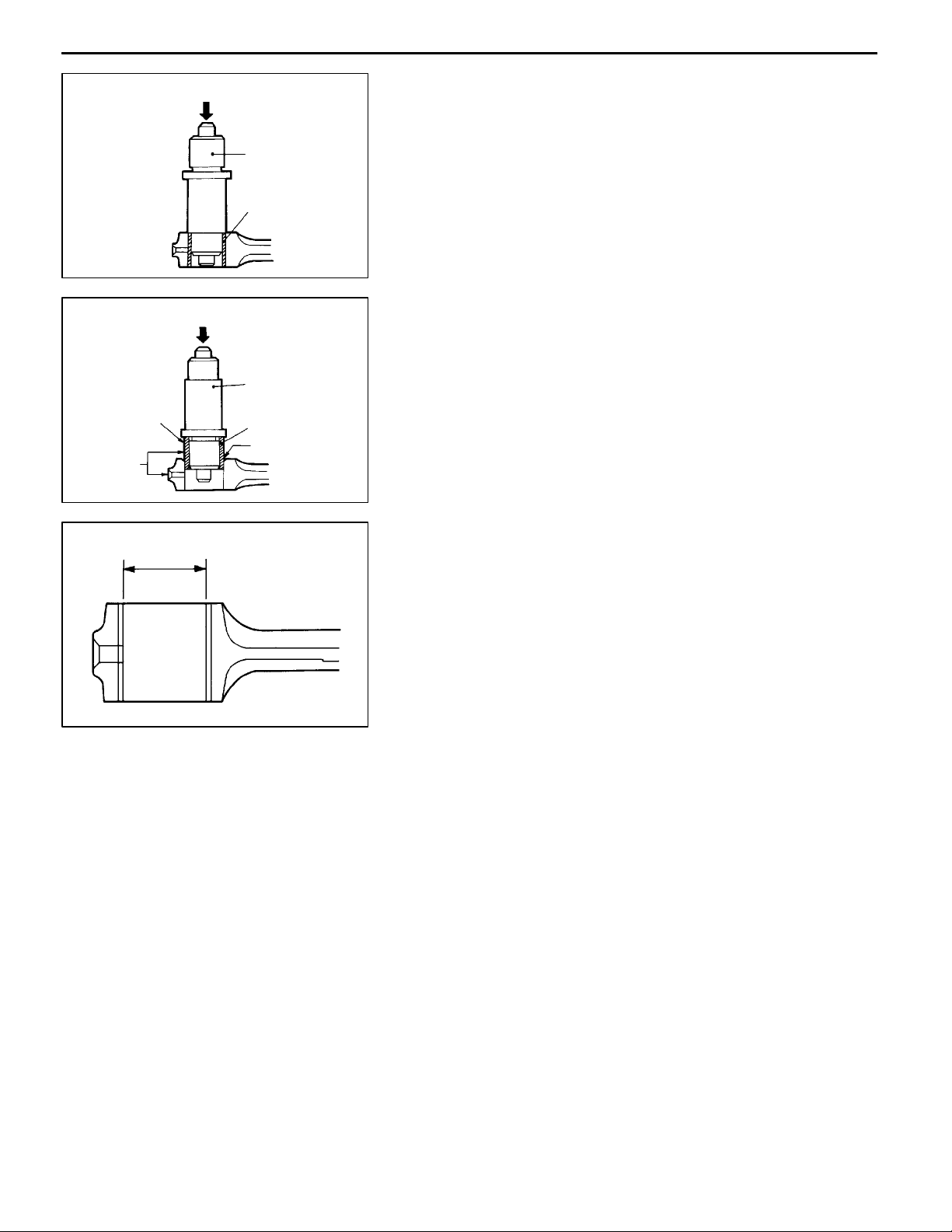
11A-11-6
4D68 ENGINE (E-W) -
Pistons and Connecting Rods
Removal
Installation
Apply oil
Align oil
holes
CONNECTING ROD BUSHING REPLACEMENT
(1) Using the special tool, remove the bushing.
MD998702
Bushing
DEN204
(2) Using the special tool, install the bushing, aligning the
oil hole of the bushing with the oil hole at the small end
of the connecting rod.
MD998702
Bushing
Chamfered end
DEN205
(3) Finish the bushing I.D. to the standard value.
d
Bushing I.D. (d) standard value:
25.015 - 25.025 mm
Bend (Parallelism between big end center line and
small end center line): 0.05 mm
Twist (Deflection between big end center line and small
end center line): 0.1 mm
DEN206
E
Dec. 1996Mitsubishi Motors Corporation
PWEE9609
Page 60

4D68 ENGINE (E-W) -
Crankshaft, Cylinder Block and Flywheel
12. CRANKSHAFT, CYLINDER BLOCK AND FLYWHEEL
REMOVAL AND INSTALLATION
132 Nm
“A”
3
11A-12-1
1
16
15
32 Nm
18
17
89
14
13
12
6
11 Nm
5
2
4
11 Nm
7
11
Apply engine oil to all
moving parts before
installation.
10
DEN0893
Removal steps
1. Flywheel bolt
2. Adapter plate
3. Flexible flywheel
4. Adapter plate
5. Crankshaft bush
6. Rear plate
7. Bell housing cover
"DA
"CA
"BA
"BA
"AA
"AA
E
8. Oil seal case
9. Oil seal
10. Bearing cap bolt
11. Bearing cap
12. Crankshaft bearing, lower
13. Crankshaft
14. Crankshaft bearing, upper
Dec. 1996Mitsubishi Motors Corporation
Caution
On the flexible wheel equipped engines, do not
remove any of the bolts “A” of the flywheel shown
in the illustration.
The balance of the flexible flywheel is adjusted in
an assembled condition. Removing the bolt,
therefore, can cause the flexible flywheel to be out
of balance, giving damage to the flywheel.
PWEE9609
15. Check valve
16. Oil jet
17. Cylinder sleeve
18. Cylinder block
Page 61

11A-12-2
4D68 ENGINE (E-W) -
Crankshaft, Cylinder Block and Flywheel
No.2
No.5
Timing belt side
No.3
No.1
Location of
identification colors
Cylinder block bearing
bore identification mark
No.3
No.2
No.1
Cylinder bore size
mark (reference)
No.4
No.5
No.4
6EN0705
6EN1184
INSTALLATION SERVICE POINTS
"AA
When the bearing needs replacing, select and install a proper
bearing by the following procedure.
(1) Measure the crankshaft journal diameter and confirm its
(2) The cylinder block bearing bore diameter identification
(3) Select a proper bearing from the above table on the basis
[Example]
1. If the measured value of a crankshaft journal outer diameter
2. Next, check the cylinder block bearing hole identification
CRANKSHAFT BEARING INSTALLATION
classification from the following table. In the case of a
crankshaft supplied as a service part, identification colors
of its journals are painted at the positions shown in the
illustration.
marks are stamped at the position shown in the illustration
from front to rear beginning at No. 1.
Crankshaft journal
Classification
cation
1 None Yellow 56.994 - 0 1
2 None None 56.988 - 0 2
3 None White 56.982 - 0 3
Identification color O.D.
Produc-
tion part
Service
part
57.000
56.994
56.988
mm
mm
Cylinder
block
block
bearing
bore
diameter
identifica-
tion mark
1 2
2 3
1 3
2 4
1 4
2 5
Bearing
identifica-
identifica-
tion mark
(for ser-
vice part)
of the identification data confirmed under items (1) and
(2).
is 57.000 mm, the journal is classified as “1” in the table.
In case the crankshaft is also replaced by a spare part,
check the identification colors of the journals painted on
the new crankshaft. If the color is yellow, for example,
the journal is classified as “1”.
mark stamped on the cylinder block. If it is “0”, read the
“Bearing identification mark” column to find th e
identification mark of t he bearing to be used. In this case,
it is “1”.
Lower bearing
(for No.1,2,4,5)
Upper and lower bearings
(for center)
E
Grooveless
Upper bearing
(for No.1,2,4,5)
Grooveless
Dec. 1996Mitsubishi Motors Corporation
Grooved
1EN0272
(3) Install the bearings having an oil groove to the cylinder
block. Install the grooveless bearing with thrust flanges
in the center bearing bore in the cylinder block.
(4) Install the bearings having no oil groove to the bearing
caps.
PWEE9609
Page 62

4D68 ENGINE (E-W) -
Crankshaft, Cylinder Block and Flywheel
11A-12-3
8
Arrow
mark
Paint mark
Shank length
4
9EN0477
15
263Q7
6EN0624
Paint mark
"BA
BEARING CAP / BEARING CAP BOLT
INSTALLATION
(1) Install the bearing caps so that their arrows are directed
to the timing belt side.
(2) Before installing the bearing cap bolts, check that the
shank length of each bolt meets t h e limit. If the limit is
exceeded, replace the bolt.
Limit: 71.1 mm
(3) Apply engine oil to the threaded portion and bearingsurface
of the bolt.
(4) Tighten the bolts to 25 Nm in the specified tightening
9
sequence.
(5) Make a paint mark on the head of each bolt.
(6) Make a paint mark on the bearing cap at the position
90° to 100° from the paint mark made on the bolt in the
direction of tightening the bolt.
(7) According to the specified tightening sequence, give a
90° to 100° turn to each bolt and make sure that the
paint mark on the bolt and that on the cap are in alignment.
90°- 100
°
6AE0299
Caution
D
If the bolt is turned less than 90°, proper fastening
performance may not be expected. When
tightening the bolt, therefore, be careful to give
a sufficient turn to it.
D
If the bolt is overtightened (exceeding 100°), loosen
the bolt completely and then retighten it by
repeating the tightening procedure from step (1).
(8) After installing the bearing caps, make sure that the
crankshaft turns smoothly and the end play is correct.
If the end play exceeds the limit, replace the crankshaft
bearings.
Standard value: 0.05 - 0.18 mm
Limit: 0.25 mm
6EN0625
E
Dec. 1996Mitsubishi Motors Corporation
PWEE9609
Page 63

11A-12-4
4D68 ENGINE (E-W) -
Crankshaft, Cylinder Block and Flywheel
MB990938
MD998776
6EN0709
6EN0626
"CA
"DA
OIL SEAL INSTALLATION
OIL SEAL CASE INSTALLATION
Specified sealant:
Mitsubishi Genuine Part No. MD970389 or
equivalent
Plastic
gauge
INSPECTION
CRANKSHAFT OIL CLEARANCE (PLASTIC GAUGE
METHOD)
(1) Remove oil from the crankshaft journal and the crankshaft
bearing.
(2) Install the crankshaft.
(3) Cut the plastic gauge to the same length as the width
of the bearing and place it on the journal in parallel with
its axis.
6EN0703
(4) Install the crankshaft bearing cap carefully and tighten
the bolts to the specified torque.
(5) Carefully remove the crankshaft bearing cap.
(6) Measure the width of the plastic gauge at its widest part
by using a scale printed on the plastic gauge package.
Standard value: 0.02 - 0.04 mm
Limit: 0.1 mm
Plastic
gauge
6EN0623
E
Dec. 1996Mitsubishi Motors Corporation
PWEE9609
Page 64

4D68 ENGINE (E-W) -
Crankshaft, Cylinder Block and Flywheel
11A-12-5
CD E
A
B
A
B
12 mm
F
G
(1) Visually check for cracks, rust, and corrosion, and inspect
the cylinder block using a flaw detecting agent. Rectify
defects where possible or replace the cylinder block.
(2) Check the cylinder block’s top surface for distortion using
a straight edge and thickness gauge. Be sure to make
measurements with the straight edge placed in thedirection
of A, B,.. and G as shown in the illustration. Before
measurements, make sure that the top surface is free
of gasket chips a n d other foreign material. If the distortion
CYLINDER BLOCK
9EN0074
is excessive, replace the cylinder block.
Standard value: 0.05 mm
Limit: 0.1 mm
(3) Check the cylinder sleeve wall for scratches and seizure.
If defects are evident, replace the cylinder sleeve. Measure
the cylinder sleeve inner diameter at the points shown
in the illustration. If it is badly worn, replace.
Standard value: 82.70 - 82.73 mm
Conicity: 0.01 mm
Center
Bottom
Piston O.D.
6EN0553
Thrust
direction
6EN0554
BORING CYLINDER
(1) Oversize pistons to be used should be determined on
the basis of the largest bore cylinder.
Piston size identification
Size Identification mark
0.50 mm O.S. 0.50
1.00 mm O.S. 1.00
NOTE
Size mark is stamped on the piston top.
(2) Measure outside diameter of piston to be sued. Measure
it in thrust direction as shown.
(3) Based on the measured piston O.D., calculate the boring
finish dimension.
Boring finish dimension = Piston O.D. + (Clearance
between piston O.D. and cylinder) - 0.02 mm
(honing margin)
E
Dec. 1996Mitsubishi Motors Corporation
PWEE9609
Page 65

11A-12-6
4D68 ENGINE (E-W) -
Crankshaft, Cylinder Block and Flywheel
(4) Bore all cylinders to the calculated boring finish dimension.
Caution
To prevent distortion that may result from temperature
rise during honing, bore cylinders, in the order of
No. 2, No. 4, No. 1 and No. 3.
(5) Hone to the final finish dimension (Piston O.D. + clearance
between piston O.D. and cylinder.)
(6) Check the clearance between piston and cylinder.
Clearance between piston and cylinder:
0.03 - 0.05 mm
NOTE
When boring cylinders, finish all of four cylinders to the
same oversize. Do not bore only o ne cylinder to an
oversize.
P view
Thinned cylinder
sleeve
Round this surface
P
Face round side
toward the cylinder
block
DEN238
DEN239
CYLINDER SLEEVE CHANGE PROCEDURES
REMOVAL
(1) Fix the cylinder block to a boring machine and center
it. Center at the lower portion of the cylinder sleeve where
there is less uneven wear.
(2) Bore to the sleeve wall thickness of about 0.5 mm.
(3) Machine the screwdriver as illustrated and insert it between
the cylinder sleeve and cylinder block. Lightly hit it to break
the sleeve.
When doing so, be careful not to damage the cylinder
block wall.
E
Dec. 1996Mitsubishi Motors Corporation
PWEE9609
Page 66

4D68 ENGINE (E-W) -
Crankshaft, Cylinder Block and Flywheel
11A-12-7
Y direction
X direction
12 mm
Center
Lower
Cylinder sleeve
Hydraulic press
DEN116
INSPECTION
(1) After removing the cylinder sleeve, check the cylinder block
sleeve hole surface.
If there is damage, insufficient interference-fit-margin or
other problems, bore the cylinder block sleeve hole to
an oversize.
(2) To checkthe interference, measure both the cylinder sleeve
O.D. and cylinder block sleeve hole I.D. at the positions
,D2and D3in both X and Y directions.
D
1
(3) If the average of the differences between measured values
is smaller than 0.12 mm, then bore the sleeve hole to
0.5 mm oversize and install an oversize sleeve. If the
average is larger than 0.175 mm, bore the sleeve hole
to the extent that the difference falls within a range of
0.12 to 0.175 mm, then install a standard cylinder sleeve.
Caution
D
If one cylinder requires oversize machining,
oversize it with the other cylinder sleeves removed.
Machining while the sleeves remain in the other
cylinders may disturb roundness.
INSTALLATION
When cylinder block sleeve hole has not been bored
(1) Amply apply press oil to the cylinder block sleeve hole
and sleeve outer circumference.
(2) Apply a disc [diameter 100 mm, thickness 20 mm or more]
to the top of the sleeve and press fit using a hydraulic
press.
To be flush
Cylinder
sleeve
Top end
Bottom end
Chamfered
Installation load: 22,000 N or more
DEN241
(3) Install with the chamfered end first as illustrated. Continue
until the sleeve upper end is flush with the block upper
end.
DEN242
(4) Cut off the top end of the cylinder block in order to make
the cylinder block flush with the sleeve. Cut off the minimum
top end portion of the cylinder block necessary to make
them flush. Do not cut off more than 0.2 mm.
Cylinder
block
DEN243
E
Dec. 1996Mitsubishi Motors Corporation
PWEE9609
Page 67

11A-12-8
4D68 ENGINE (E-W) -
Crankshaft, Cylinder Block and Flywheel
0.5 mm
30
Cylinder sleeve
°
DEN244
(5) Chamfer the cylinder sleeve top end as illustrated.
(6) The service cylinder sleeve has the I.D. machined to 81.5
to 81.7 mm. After installation of the sleeve, therefore,
hone the I.D. to the standard value.
Cylinder I.D.: 82.70 - 82.73 mm
Honing finished surface roughness: 2 - 4
Honing cross hatch angle: 15 - 25
°
m
Cylinder bore squareness: 0.05 mm
When boring the cylinder block sleeve hole
(1) Prepare a cylinder sleeve of 0.5 mm oversize (identification
color: red).
(2) Hone the cylinder block sleeve hole to 86.13 to 86.15
mm.
(3) Install the cylinder sleeve and finish the I.D. The installation
and machining procedures are the same as in the case
when the block sleeve hole has not been bored.
INSPECTION AFTER ASSEMBLY
(1) After assembling the crankshaft, piston, etc., check the
piston protrusion.
If the protrusion exceeds the limit, change the piston and
connecting rod in order to reduce the protrusion to within
the limit.
Protrusion
(2) If the protrusion still exceeds the limit after piston
reassembly, replace the cylinder block.
Limit: 0.823 mm
DEN0798
E
Dec. 1996Mitsubishi Motors Corporation
PWEE9609
Page 68

NOTES
 Loading...