

Page 1

For Gulf Countries
GROUP INDEX
2014 Model
Shop Manual
4D3 diesel engine
FOREWORD
This Shop Manual is published for the information and
guidance of personnel responsible for maintenance of
Mitsubishi Fuso CANTER series truck, and includes procedures for adjustment and maintenance services.
We earnestly look forward to seeing that this manual is
made full use of in order to perform correct services with
no wastage.
GENERAL....................................
ENGINE .......................................
LUBRICATION.............................
FUEL AND ENGINE
CONTROL ...................................
COOLING ....................................
INTAKE AND EXHAUST .............
00
11
12
13
14
15
For more details, please consult your nearest authorized
Mitsubishi Fuso dealer or distributors.
Kindly note that the specifications and maintenance service figures are subject to change without prior notice in
line with improvement which will be effected from time to
time in the future.
OCTOBER 2013
Applicable models (engine)
4D33
4D34T4
©2013 Mitsubishi Fuso Truck & Bus Corporation Printed in Japan
Page 2

This Shop Manual contains the information classified into the following groups.
If any system or equipment has two or more variations with significantly different construction, the variations are
handled as different groups. These groups are identified by different alphabets preceded by the same number.
1. ENGINE volume (Pub.No.00ELT0042)
Group No. Group subject
00 GENERAL
11 ENGINE
12 LUBRICATION
13 FUEL AND ENGINE CONTROL
14 COOLING
15 INTAKE AND EXHAUST
2. CHASSIS Supplement volume (Pub.No.00ELT0043)
Group No. Group subject
00 GENERAL
22 MANUAL TRANSMISSION
34 REAR SUSPENSION
35E ANTI-LOCK BRAKE SYSTEM (ABS)
37B STEERING <POWER STEERING (Except FB70)>
41 BUMPER, FRAME AND REAR BODY
42 CAB MOUNTING AND TILT
55 HEATER, AIR-CONDITIONER AND VENTILATION
3. ELECTRICAL volume (Pub.No.00ELT0044)
Group No. Group subject
54 ELECTRICAL
Page 3

GROUP 00 GENERAL
VEHICLE MODEL CODING SYSTEM................................................ 00-2
EQUIPMENT TYPE CODES LIST ...................................................... 00-3
POWER TRAIN TABLE ...................................................................... 00-4
HOW TO READ THIS MANUAL ......................................................... 00-6
CHASSIS NUMBER, VEHICLE IDENTIFICATION NUMBER,
ENGINE NUMBER AND NAME PLATE ........................................... 00-14
PRECAUTIONS FOR MAINTENANCE OPERATION
1. General Precautions ................................................................... 00-16
2. Handling of Battery..................................................................... 00-19
3. Handling of Sensors, Relays and Electronic Control Units ......... 00-19
4. Handling Precautions for Electric Circuits .................................. 00-20
5. Service Precautions for Alternators............................................ 00-23
6. Intermittent Faults ...................................................................... 00-24
7. Precautions for Arc Welding....................................................... 00-25
8. Precautions When Repainting .................................................... 00-25
JACKING UP THE VEHICLE............................................................ 00-26
DIAGNOSIS CODES
1. Diagnosis Codes ........................................................................ 00-28
2. Reading and Erasing the Diagnosis Code................................... 00-29
13A
13E
TABLE OF STANDARD TIGHTENING TORQUES
1. Tightening Torques..................................................................... 00-34
2. Table of Standard Tightening Torque .......................................... 00-34
00-1
Page 4
VEHICLE MODEL CODING SYSTEM
1 7
3 52
4
9
86
1010
11
12 13
FE73CB
1 Basic vehicle type F Cab-over engine truck
2 Load capacity, drive system
3 Cab type
4 Vehicle variations, Suspension
5 Engine
6 Wheelbase
7 Chassis arrangement for use
8 Rear tire arrangement, Payload 6
9 Vehicle specification
10 Steering position L Left-hand drive vehicle
11 t o
Export specification
13
E 2 ton class and over, 4 × 2
G 2 ton class and over, 4 × 4
7 Standard-width cab
8Wide cab
3
4
5
C4D33
P4D34T4
B 2500 mm
C 2750 mm
E 3350 mm
G 3850 mm
H 4710 mm
None Standard use
D Dump use
ZWide frame
S With turbocharger
WCrew cab
None Standard
Rigid axle
Light duty vehicle (Payload 1500 to 3000 kg)
Rigid axle
Light duty vehicle (G.V.M 6000 to 6900 kg)
Rigid axle
Light duty vehicle (G.V.M. 7000 kg or more)
Rear double
Payload 3000 kg to 4000 kg
• The information from to is indicated on vehicles.
00-2
Page 5
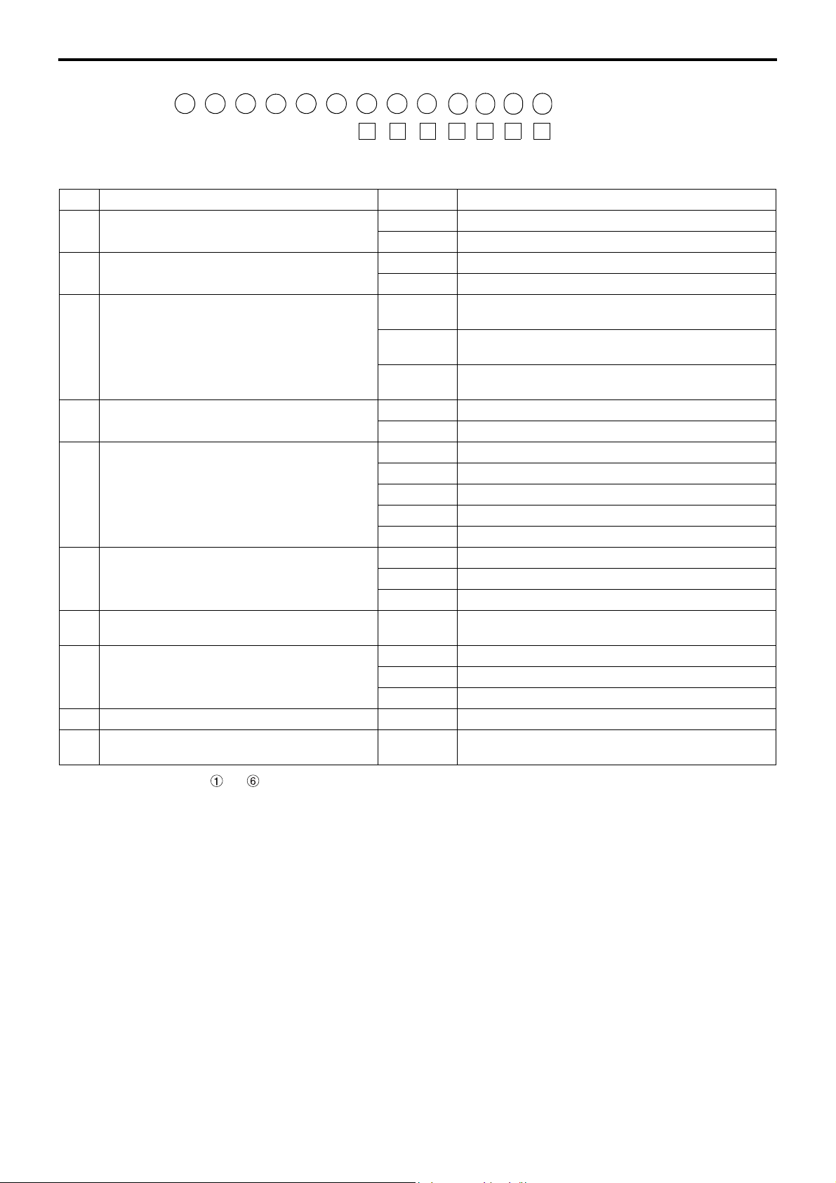
EQUIPMENT TYPE CODES LIST
Component Name plate marking Code description
Engine
4D34T4 4 D 3 4 T 4
Power version number
Turbocharged
Order of development within same series
Order of development among different series
Diesel engine
No. of cylinders (4)
Clutch
C4W30 C 4 W 30
Disc OD
Facing material (W: Woven)
Load carrying capacity of truck class (tonnage)
on which the clutch is primarily used
Initial letter of the clutch
Transmission
M035S5 M 035 S 5
Forward speeds
Type of mesh (S: Synchromesh)
Load carrying capacity of truck class (tonnage)
on which the clutch is primarily used
Initial letter of the transmission
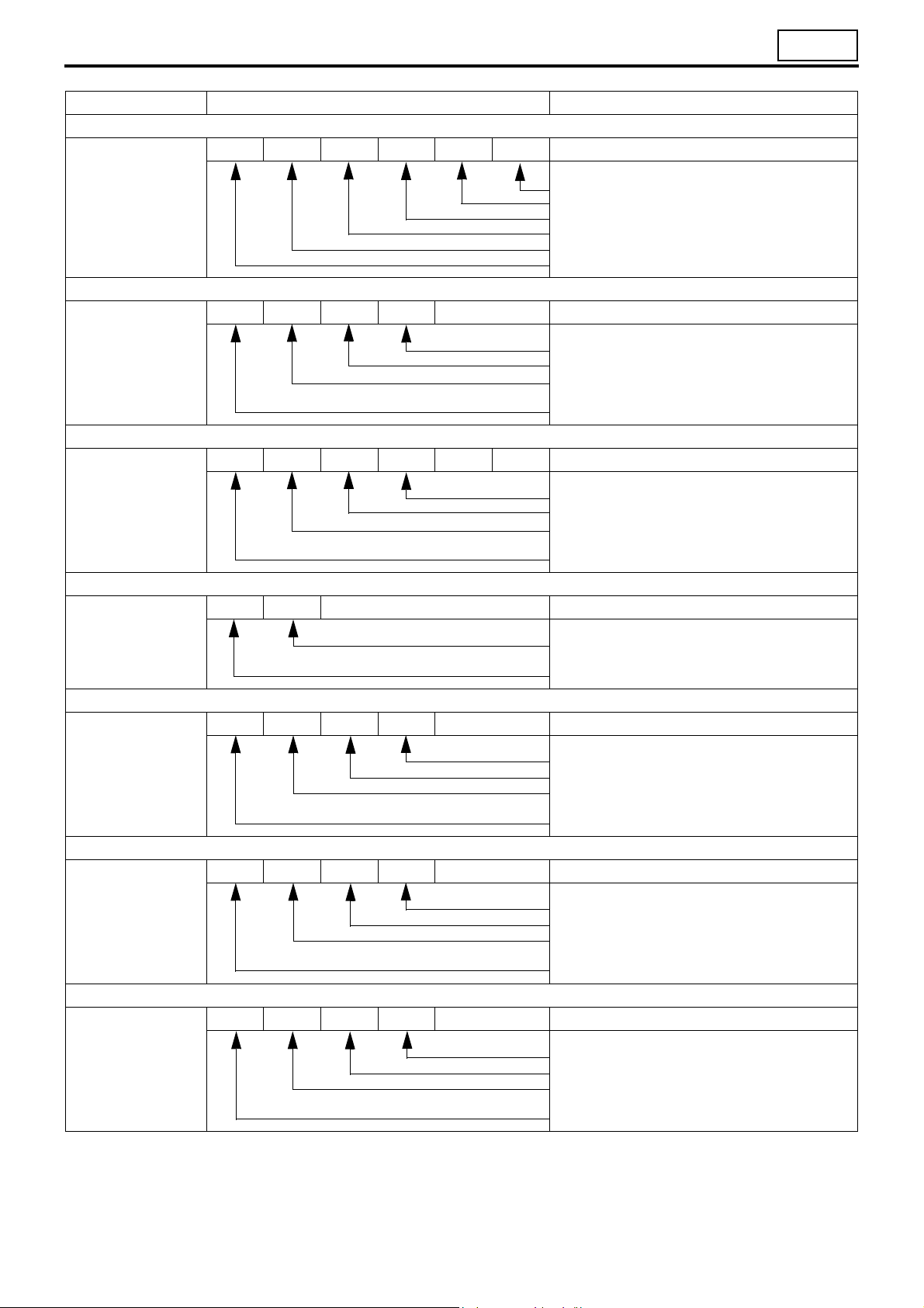
Propeller shaft
P3 P 3
00
Front axle
F200T F 200 T W
Rear axle
R035T R 03 5 T
Reduction and differential
D035H D 03 5 H
Load carrying capacity of truck class (tonnage)
on which the clutch is primarily used
Initial letter of the propeller shaft
Axle type
Vehicle type (T: Truck)
Load carrying capacity of truck class (tonnage)
on which the clutch is primarily used
Initial letter of the front axle
Vehicle type (T: Truck)
Order of development within same series
Load carrying capacity of truck class (tonnage)
on which the clutch is primarily used
Initial letter of the rear axle
Tooth profile (H: Hypoid gear)
Order of development within same series
Load carrying capacity of truck class (tonnage)
on which the clutch is primarily used
Initial letter of the reduction & differential
00-3
Page 6

POWER TRAIN TABLE
• FE
Vehicle model Engine Clutch Transmission
FE73CB6LADG 4D33 C4W30 M035S5 P3 F200T R033T D033H
FE73CE6LADG 4D33 C4W30 M035S5 P3 F200T R033T D033H
FE84CCD6LGSG 4D33 C4W30 M035S5 P3 F200T R033T D033H
FE84CE6LADG 4D33 C4W30 M035S5 P3 F200T R033T D033H
FE84CE6WLGSG 4D33 C4W30 M035S5 P3 F200T R033T D033H
FE84CG6LADG 4D33 C4W30 M035S5 P3 F200T R033T D033H
FE85CC6LADG 4D33 C4W30 M035S5 P3 F200T R035T D035H
FE85CG6LADG 4D33 C4W30 M035S5 P3 F200T R035T D035H
FE85CHZLADG 4D33 C4W30 M035S5 P3 F200T R040 D040H
FE85PHZSLADG 4D34T4 C4W30 M035S5 P3 F200T R040 D040H
Propeller
shaft
Front axle Rear axle
• FG
Vehicle model Engine Clutch Transmission
FG83CE6LGSG 4D33 C4W30 M035S5
FG83CE6WLGSG 4D33 C4W30 M035S5
Propeller
shaft
Front: P2
Rear: P3
Front: P2
Rear: P3
Front axle Rear axle
F200TW R035T
F200TW R035T
Reduction &
Differential
Reduction &
Differential
Front: D1H
Rear: D033H
Front: D1H
Rear: D033H
00-4
Page 7

M E M O
00
00-5
Page 8

HOW TO READ THIS MANUAL
This manual consists of the following parts:
• Specifications
• Structure and Operation
• Troubleshooting
• Circuits
• Electrical Equipment Installation Positions
• Inspection of Electrical Equipment
• On-vehicle Inspection and Adjustment
• Service procedures
• Connector configuration chart
On-vehicle Inspection and Adjustment
• Procedures for inspection and adjustment of individual parts and assemblies as mounted on the vehicle are de-
scribed including specific items to check and adjust. Specified or otherwise, inspection should be performed for
looseness, play, backlash, crack, damage, etc.
Service procedures
• Procedures for servicing components and parts off the vehicle are described centering on key points in their re-
moval, installation, disassembly, reassembly, inspection, etc.
Inspection
• Check items subject to “acceptable/unacceptable” judgement on the basis of service standards are all given.
• Some routine visual checks and cleaning of some reused parts are not described but must always be included in
actual service work.
Caution
• This service manual contains important cautionary instructions and supplementary information under the following
four headings which identify the nature of the instructions and information:
DANGER
WARNING
CAUTION
NOTE
Terms and Units
• Front and rear
The forward running direction of the vehicle is referred to as the front and the reverse running direction is referred
to as the rear.
• Left and right
Left hand side and right hand side, when facing the forward running direction of the vehicle, are respectively left
and right.
Precautions that should be taken in handling potentially dangerous substances
such as battery fluid and coolant additives.
Precautionary instructions, which, if not observed, could result in serious injury or
death.
Precautionary instructions, which, if not observed, could result in damage to or destruction of equipment or parts.
Suggestions or supplementary information for more efficient use of equipment or
better understanding.
Standard value
• Standard value dimensions in designs indicating: the design dimensions of individual parts, the standard clear-
ance between two parts when assembled, and the standard value for an assembly part, as the case may be.
Limit
• When the value of a part exceeds this, it is no longer serviceable in respect of performance and strength and must
be replaced or repaired.
00-6
Page 9

00
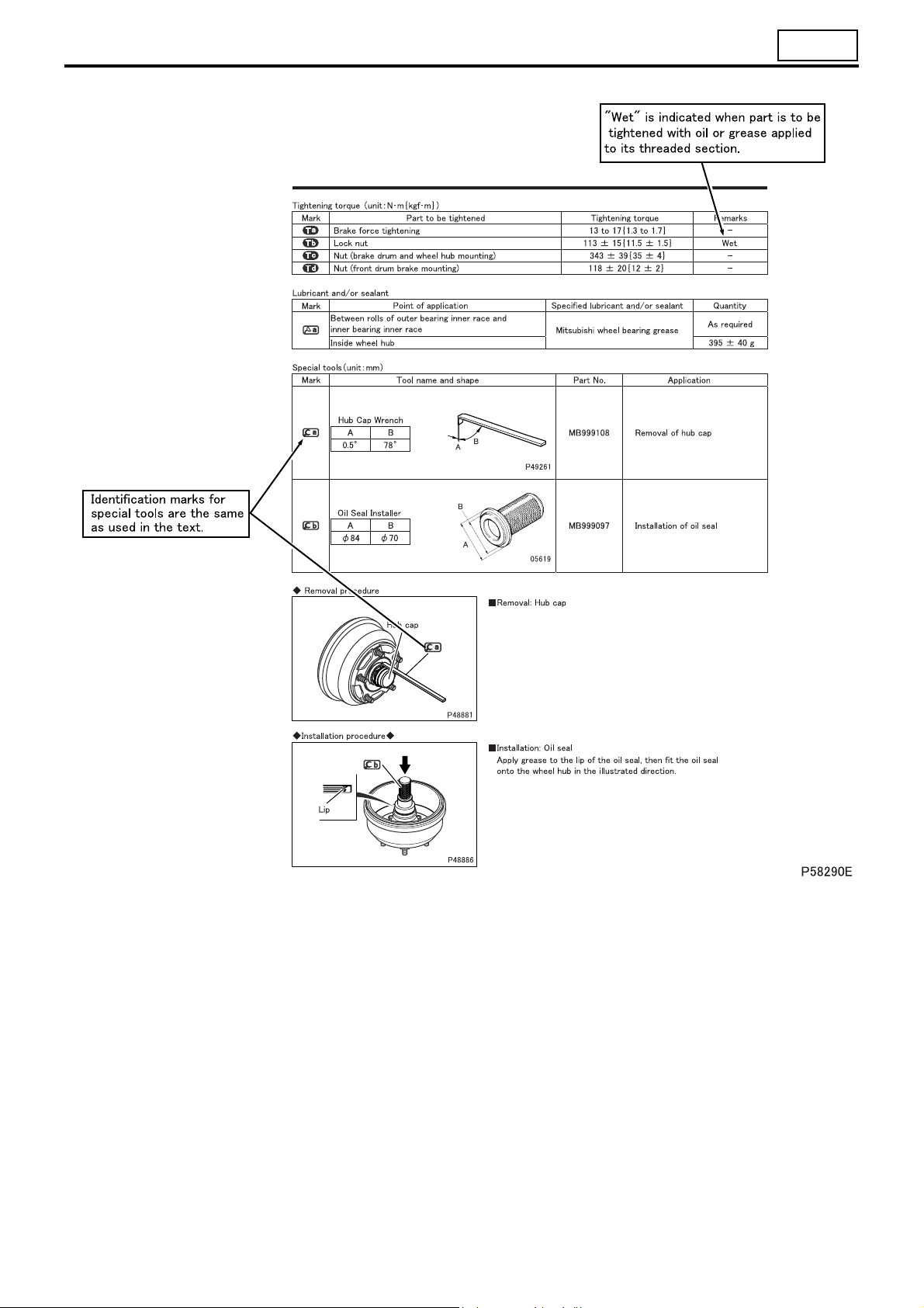
Tightening torque
• Values are directly specified for out-of-standard tightening torques for bolts and nuts.
• Where there is no specified figure for tightening torque, follow the table covering standard tightening torques.
(Values for standard tightening torques are based on thread size and material.)
• When the item is to be tightened in a wet state, “wet” is indicated. Where there is no indication, read it as dry.
Units
• Tightening torques and other parameters are given in SI* units with metric units added in brackets { }.
*SI: Le Système International d’Unités
Example: 390 N·m {40 kgf·m}
Metric unit
SI unit
Unit SI unit {metric unit} Conversion factor
Force N {kgf} 9.80665 N {1 kgf}
Moment of force N·m {kgf·m} 9.80665 N·m {1 kgf·m}
Positive pressure kPa {kgf/cm2} 98.0665 kPa {1 kgf/cm2}
Pressure
Volume dm
Heat quantity J {kcal} 4186.05 J {1 kcal}
Heat flow W {kcal/h} 1.16279 W {1 kcal/h}
Power kW {PS} 0.7355 kW {1 PS}
Vacuum pressure
kPa {mmHg} 0.133322 kPa {1 mmHg}
Pa {mmH
O} 9.80665 Pa {1 mmH2O}
2
3
{L} 1 dm3 {1 L}
00-7
Page 10
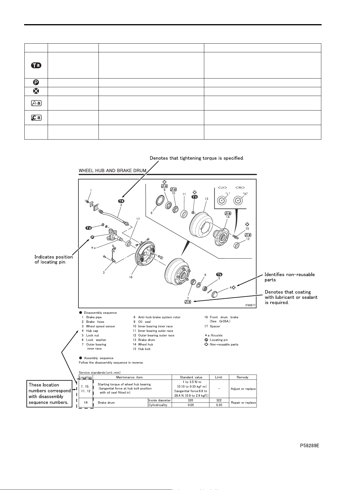
HOW TO READ THIS MANUAL
Illustrated Parts Breakdown and Service Procedures
Symbol Denotation Application Remarks
Tightening torque
Locating pin Parts to be positioned for installation
Non-reusable parts Parts not to be reused
Lubricant and/or
sealant
Special tool
*a Associated part
Parts not tightened to standard torques
(standard torques specified where necessary for servicing)
Parts to be coated with lubricant or sealant
for assembly or installation
Parts for which special tools are required for
service operation
Parts associated with those removed/disassembled for servicing
Specified values shown in table
See Table of Standard Tightening Torques for
parts for which no tightening torques are specified.
Necessary lubricant and/or sealant, quantity required, etc. are specified in table.
Tool name/shape and part number are shown in
table.
00-8
Page 11
00
00-9
Page 12

HOW TO READ THIS MANUAL
How to Read Circuits (Electrical)
00-10
Page 13
00
1.1 Index number: to
• Index numbers are used as reference numbers for electrical circuits. Each electrical circuit has been assigned its
own index number.
100 999
1.2 Key number: A01 to Z99
• Key numbers indicate electrical equipment installation locations. The installation location of an electrical equip-
ment can be easily found using its key number shown in a circuit diagram.
All of the electrical equipment installation locations are listed in Gr54-10.
1.3 Part name
1.4 Connector type (type indication)
• A list of the connectors used is included in Gr54-14.
1.5 Connector terminal number
1.6 Major harness division
• Major harness divisions are shown.
1.7 Wiring variations between different specifications
• Variations in wiring/circuit between different vehicle specifications are clearly indicated as shown.
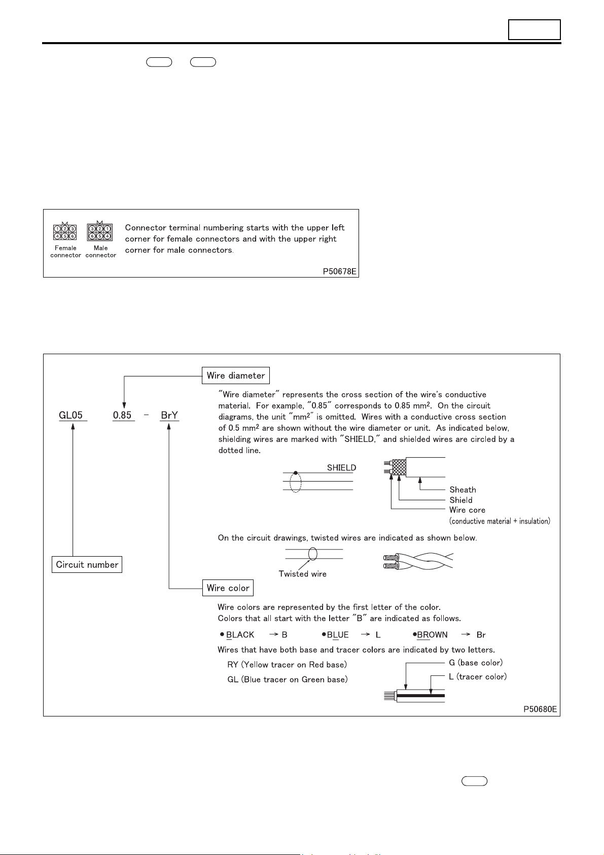
1.8 Circuit number, wire diameter, wire color
1.9 Code number: #001 to #999
• Code numbers are reference numbers to find individual electrical equipment inspection procedures. The inspec-
tion procedure for an electrical equipment can be found using its code number shown in a circuit diagram.
1.10Grounding point: [1] to [99]
• Locations where wires are grounded to the vehicle. All of the grounding points are listed in .
130
1.11 Harness connection
• The arrow in the wiring diagram indicates where harnesses are connected, and NOT the flow of electricity.
00-11
Page 14

HOW TO READ THIS MANUAL
Wire color
Wire color Base color + tracer
BW
BBlack
BP
BrW
Br Brown
BrGr
GW
G Green
GGr
GrL,
Gr,
Gy
LBlue
Lg
O Orange OL
PPinkPB
Pu Purple
RRed
Sb Sky blue
V Violet VY
WWhite
Y Yellow
green
GyL
Gray
GrG
LW
LGr Blue/gray LBr
Light
LgR
RW
RBr
WR
WBr
YR
YP
Black/
Black/
Brown/
Brown/
Green/
Green/
green
green/
Orange/
brown
Violet/yel-
White/
White/
brown
Yel lo w/
Yel lo w/
white
pink
white
gray
white
gray
Gray/
blue
Gray/
Blue/
white
Light
red
blue
Pink/
black
Red/
white
Red/
low
red
red
pink
BY
BV
BrB
BrV
GR
GBr
GrR,
GyR
GrBr
LR Blue/red LY
LgY
OB
PG
RB
Rgr
VW
WB
WY
YB
YV
Black/
yellow
Black/
violet
Brown/
black
Brown/
Violet
Green/
red
Green/
brown
Gray/
red
Gray/
brown
Blue/
brown
Light
green/
yellow
Orange/
black
Pink/
green
Red/
black
Red/
Gray
Violet/
white
White/
black
White/
yellow
Yellow/
black
Yellow/
violet
BR Black/red BG
B Br
BrY
GY
GV
GrB,
GyB
LgB
OG
PL
RY
VR Violet/red VG
WL
YG
YGr
Black/
brown
Brown/
yellow
Green/
yellow
Green/
violet
Gray/
black
Blue/
yellow
Light
green/
black
Orange/
green
Pink/
blue
Red/
yellow
White/
blue
Yell ow /
green
Yell ow /
gray
BrR
GB
GrG,
GyG
LB
LgW
PW
RG
WG
YL
YBr
Black/
green
Brown/
red
Green/
black
Gray/
green
Blue/
black
Light
green/
white
Pink/
white
Red/
green
Violet/
green
White/
green
Yel lo w/
blue
Yel lo w/
brown
BL
BrG
GL
GrW,
GyW
LO
PGr Pink/gray PV
RL Red/blue RO
VGr
WO
YW
Black/
blue
Brown/
green
Green/
blue
Gray/
white
Blue/
orange
Violet/
gray
White/
orange
Yellow/
white
BO
BrL
GO
GrY
LG
VB
WV
YO
Black/
orange
Brown/
blue
Green/
orange
Gray/
yellow
Blue/
green
Pink/
violet
Red/
orange
Violet/
black
White/
violet
Yell ow /
orange
00-12
Page 15

M E M O
00
00-13
Page 16

CHASSIS NUMBER, VEHICLE IDENTIFICATION NUMBER, ENGINE NUMBER AND NAME PLATE
• Serial chassis and engine numbers are assigned to the vehicles and engines in manufacturing sequence. Every
vehicle and engine has its own number. These numbers are required for registration and related inspection of the
vehicle.
Chassis number
Engine number
Name plate
• Name plate contains the following information.
• Month and year of manufacture
• Gross vehicle mass
• Front permissible load
• Rear permissible load
• Chassis number or vehicle identification number
00-14
Page 17

00
Vehicle identification number (V.I.N.)
Example: J L 6 B 5 E 1 K E K
(1)(2)
(4) (5) (6) (7)
(3)
(1) Country J : Japan
(2) Make L : Mitsubishi Fuso Truck & Bus
(3) Vehicle type 6 : Incomplete vehicle
(4) G.V.W./Brake system B : 3500 kg
(5) Model 5 : FE73C
(6) Series (wheelbase) 1 : 2.3 to 2.59 m
(7) Chassis cab type 1 : Cargo
5: Others
(8) Engine J : 3.097 L
(9) Check digit
(10) Model year E : 2014
(11) Plant K : Kawasaki
(12) Serial No.
(8)(9)
(10)
(11) (12)
7: Truck
< G.V. W. ≤ 1200 kg/
Hydraulic
6: FE84C
7: FE85C
8 : FG83C
9: FE85P-Z
C : 2.6 to 2.89 m
D : 2.9 to 3.19 m
E : 3.2 to 3.49 m
G: 3.8 to 4.09 m
H : 4.1 to 4.39 m
2: Dump
Diesel engine (4D34T4)
P : 4.214 L
Diesel engine (4D33)
F : 2015
G: 2016
H : 2017
00-15
Page 18
PRECAUTIONS FOR MAINTENANCE OPERATION
1. General Precautions
• Before performing service operations, inquire into the customer’s complaints and ascertain the condition by
checking the total distance traveled, the conditions under which the vehicle is operated, and other relevant factors
on the vehicle. And note the necessary information. This information will help you to service the vehicle efficiently.
• Check the location of the fault, and identify its cause. Based on
your findings, determine whether parts must be removed or disassembled. Then, follow the service procedure given in this
manual.
• Perform service operations on a level surface. Before starting,
take the following preparatory steps:
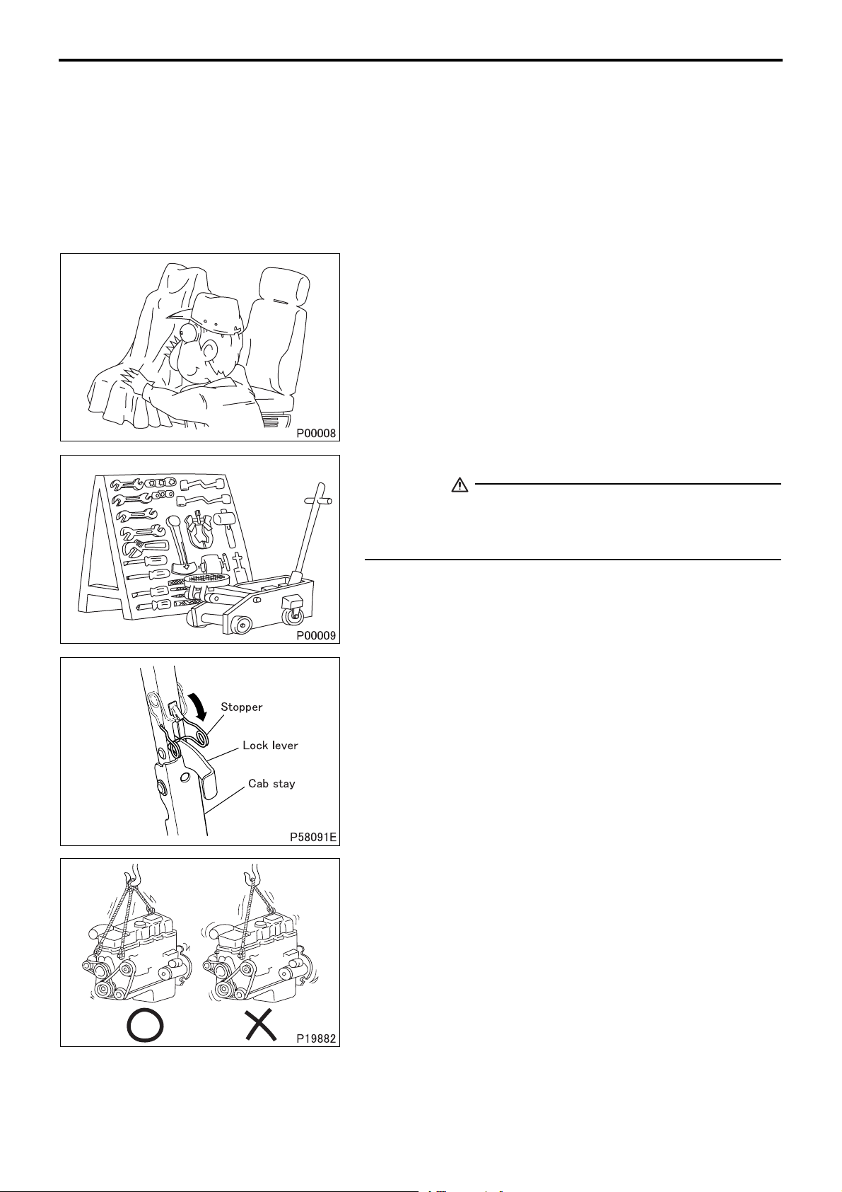
• To prevent soiling and damage, place covers over the seats,
trim and floor in the cab and over the paintwork of the body.
• Prepare all the general and special tools necessary for the job.
WARNING
• Special tools must be used wherever specified in this manual. Do not attempt to use other tools since they could
cause injuries and/or vehicle damage.
• After manually tilting the cab, be sure to engage the stopper with
the lock lever to secure the cab stay in a rigid state.
• Take extreme care when removing/installing heavy items such
as engine, transmission and axle. When lifting heavy items using
a cable etc., observe the following precautions.
00-16
• Identify the weight of the item being lifted. Use the cable that
is strong enough to support the weight.
Page 19
00
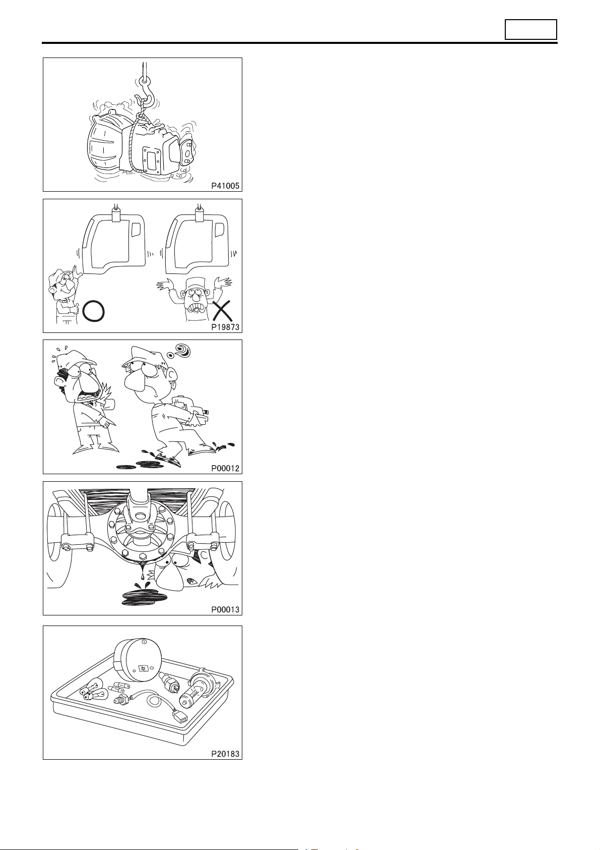
• If lifting eyes are not provided on the item being lifted, tie a ca-
ble around the item taking into account the item’s center of
gravity.
• Do not allow anyone to pass or stay under a lifted item which
may possibly fall.
• Never work in shoes that have oily soles.
When working with a partner or in a group, use pre-arranged signals and pay constant attention to safety. Be careful not to touch
switches and levers unintentionally.
• Inspect for oil leakage etc. before washing the vehicle. If the order is reversed, any oil leakage or fault that may exist could go
unnoticed during inspection.
• Prepare replacement parts ready for installation.
00-17
Page 20
PRECAUTIONS FOR MAINTENANCE OPERATION
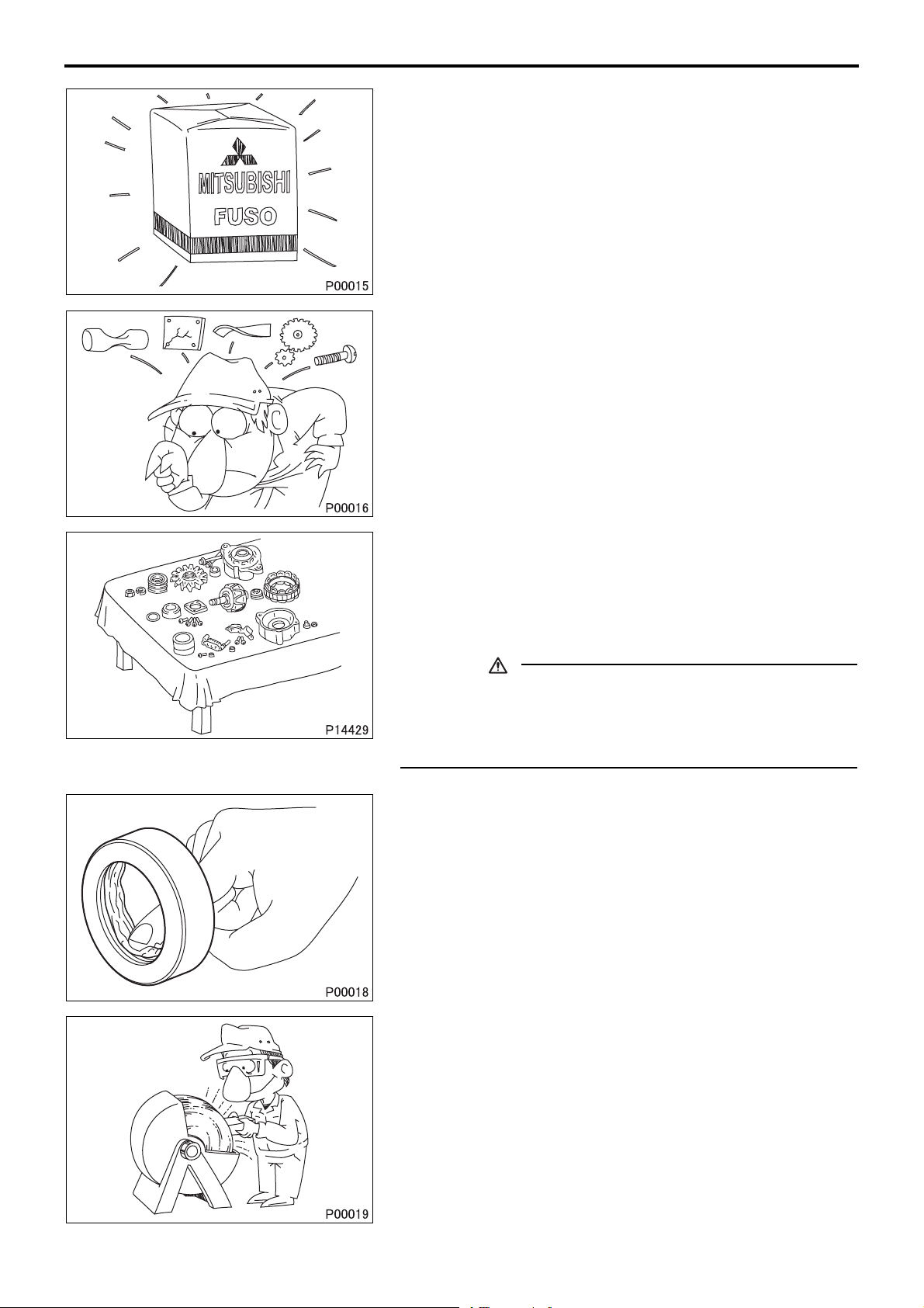
• Oil seals, packings, O-rings and other rubber parts, gaskets, and
split pins must be replaced with new ones after removal. Use
only genuine MITSUBISHI replacement parts.
• When disassembling parts, visually check them for wear, cracks,
damage, deformation, deterioration, rust, corrosion, defective rotation, fatigue, clogging and any other possible defect.
• To facilitate correct reassembly of parts, make alignment marks
on them before disassembly and arrange disassembled parts
neatly. Make punch marks and other alignment marks where
they will not detract from parts’ functionality and appearance.
• After removing parts from the vehicle, cover the area to keep it
free of dust.
CAUTION
• Be careful not to mix up identical parts, similar parts and
parts that have left/right alignments.
• Keep new replacement parts and original (removed) parts
separately.
• Apply the specified oil or grease to U-seals, oil seals, dust seals
and bearings before reassembly.
• Always use the specified oils and greases when performing inspection or replacement. Immediately wipe away any excess oil
or grease with a rag.
00-18
• Wear safety goggles when using a grinder or welder. Wear
gloves when necessary, and watch out for sharp edges and other items that might wound your hands.
Page 21
2. Handling of Battery
2.1 Handling of battery cable
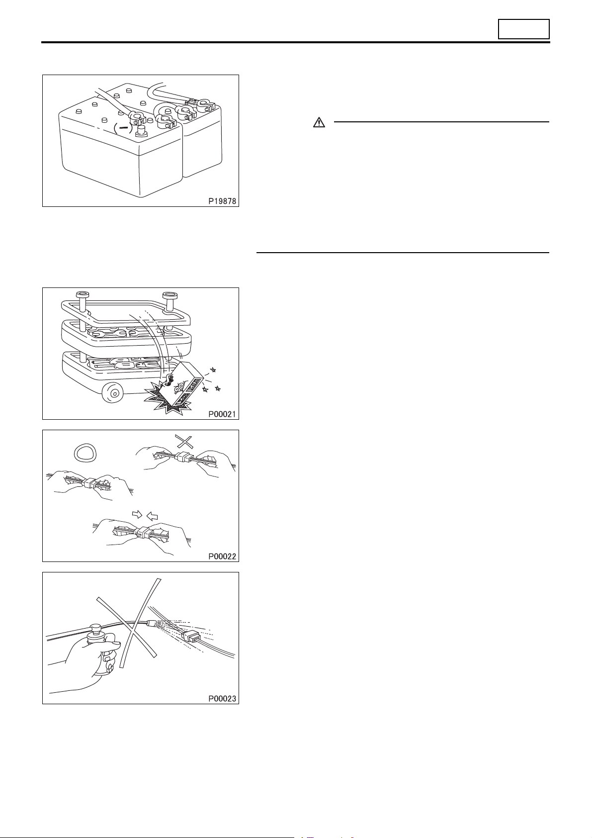
• Before working on the electrical system, disconnect the (–) bat-
tery cable to prevent short circuits.
CAUTION
• Make sure that the starter switch and lighting switches are
OFF before disconnecting or connecting battery cable.
(Semiconductor components may otherwise be damaged.)
• Disconnect the (–) battery cable, then insulate the (–) terminal of the battery and (–) battery cable with insulating tape
or the like.
• If the (–) battery cable is not disconnected, battery voltage
will remain constantly applied to the B terminal, inviting
danger of electric shock.
3. Handling of Sensors, Relays and Electronic Control Units
• Carefully handle sensors relays, and other items that are sensi-
tive to shock and heat. Do not remove or paint the cover of any
control unit.
00
• When separating connectors, grasp the connectors themselves
rather than the harnesses.
• To separate locking connectors, first push them in the direction
of the arrows. To reconnect locking connectors, push them together until they click.
• Before washing the vehicle, cover electrical parts to keep them
dry. (Use plastic sheets or equivalent.) Keep water away from
harness connectors and sensors and immediately wipe off any
water that gets on them.
00-19
Page 22
PRECAUTIONS FOR MAINTENANCE OPERATION
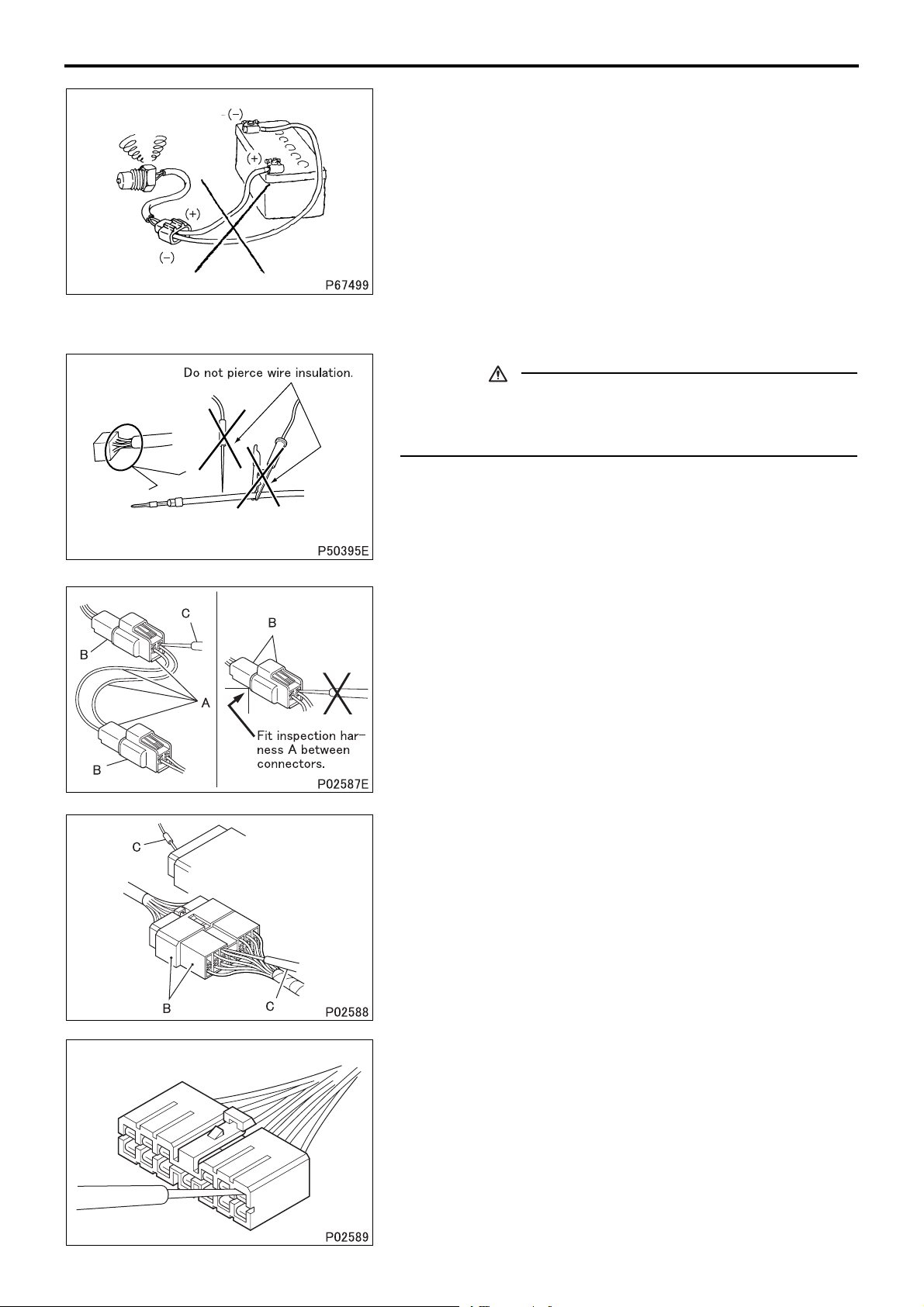
• When applying a voltage to a part for inspection purposes,
check that the (+) and (–) cables are connected properly then
gradually increase the voltage from zero. Do not exceed the
specified voltage.
Remember that control units and sensors do not necessarily operate on the battery voltage.
4. Handling Precautions for Electric Circuits
CAUTION
• Do not pierce wire insulation with test probes or alligator
clips when performing electrical inspections. Doing so can,
particularly with the chassis harness, hasten corrosion.
4.1 Inspection of harnesses
(1) Inspections with connectors fitted together
(1.1) Waterproof connectors
• Connect an inspection harness and connector A between the
connectors B of the circuit to be inspected. Perform the inspection by applying a test probe C to the connectors of the inspection harness. Do not insert the test probe C into the wire-entry
sides of the waterproof connectors since this would damage
their waterproof seals and lead to rust.
(1.2) Non-waterproof connectors
• Perform the inspection by inserting a test probe C into the wire-
entry sides of the connectors. An extra-narrow probe is required
for control unit connectors, which are smaller than other types of
connector. Do not force a regular-size probe into control unit
connectors since this would cause damage.
00-20
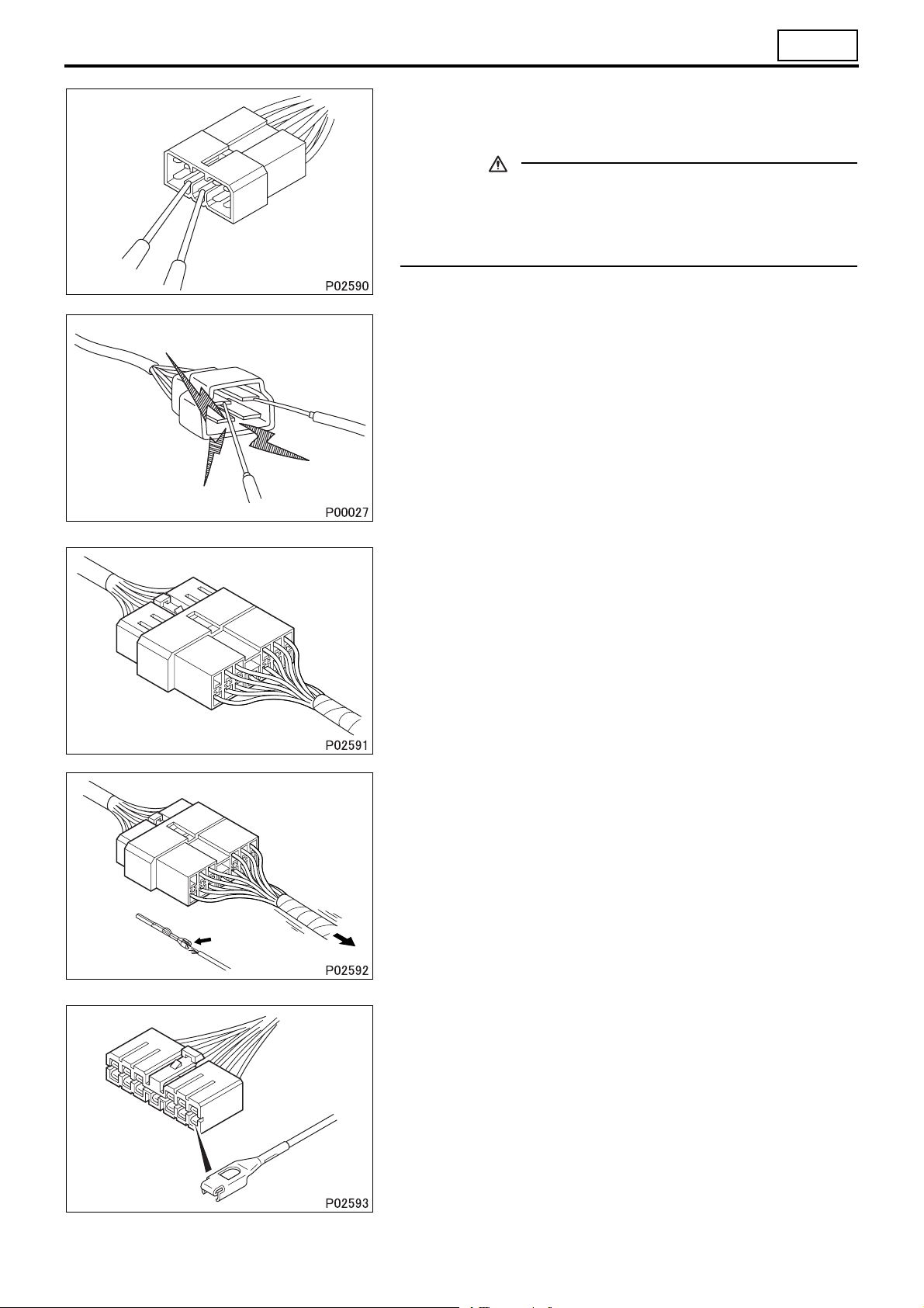
(2) Inspections with connectors separated
(2.1) Inspections on female terminals
• Perform the inspection by carefully inserting a test probe into the
terminals. Do not force the test probe into the terminals since
this could deform them and cause poor connections.
Page 23
00
(2.2) Inspections on male terminals
• Perform the inspection by applying test probes directly to the
pins.
.
CAUTION
• Be careful not to short-circuit pins together with the test
probes. With control unit connectors, short-circuiting of
pins can cause damage to the control unit’s internal circuitry.
• When using a multimeter to check continuity, do not allow the
test probes to touch the wrong terminals.
4.2 Inspection of connectors
(1) Visual inspection
• Check that the connectors are fitted together securely.
• Check whether wires have been separated from their terminals
due to pulling of the harness.
• Check that male and female terminals fit together tightly.
00-21
Page 24
PRECAUTIONS FOR MAINTENANCE OPERATION
• Check for defective connections caused by loose terminals, by
rust on terminals, or by contamination of terminals by foreign
substances.
(2) Checking for loose terminals
• If connector terminal retainers become damaged, male and fe-
male terminals may not mate with each other when the connector bodies are fitted together. To check for such terminals, gently
pull each wire and see whether any terminals slip out of their
connector housings.
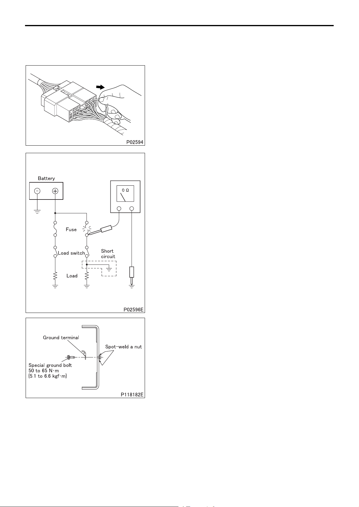
4.3 Inspections when a fuse blows
• Remove the fuse, then measure the resistance between ground
and the fuse’s load side.
Next, close the switch of each circuit connected to the fuse. If
the resistance measurement between any switch and ground is
zero, there is a short circuit between the switch and the load. If
the resistance measurement is not zero, the circuit is not currently short-circuited; the fuse probably blew due to a momentary short circuit.
• The main causes of short circuits are as follows:
• Harnesses trapped between chassis parts
• Harness insulation damage due to friction or heat
• Moisture in connectors or circuitry
• Human error (accidental short-circuiting of components)
4.4 Inspection of chassis ground
• A special ground bolt is used to tighten a ground terminal. When
servicing the ground point, be sure to follow the procedures described below:
• When reinstalling the ground bolt
Tighten the ground bolt to the specified torque.
• When relocating the ground point
A special ground bolt must be used. Spot-weld a nut to a
frame and tighten the ground bolt to the specified torque. Be
sure to apply touch-up paint to the welded point.
00-22
Page 25

5. Service Precautions for Alternators
• When servicing alternators, observe the following precautions:
• Never reverse the polarity of battery connections.
• Never disconnect the battery cables with the engine running.
Disconnection of the battery cables during engine operation
would cause a surge voltage, leading to deterioration of the diodes and regulator.
00
If the polarity of the battery connections were to be reversed,
a large current would flow from the battery to the alternator,
damaging the diodes and regulator.
• Never perform inspections using a high-voltage multimeter.
The use of a high-voltage multimeter could damage the diodes
and regulator.
• Keep alternators dry.
Water on alternators can cause internal short circuits and damage.
• Never operate an alternator with the B and L terminals short-circuited. Operation with the B and L terminals connected together
would damage the diode trio.
00-23
Page 26
PRECAUTIONS FOR MAINTENANCE OPERATION
• Disconnect the battery cables before quick-charging the battery
with a quick charger.
Unless the battery cables are disconnected, quick-charging can
damage the diodes and regulator.
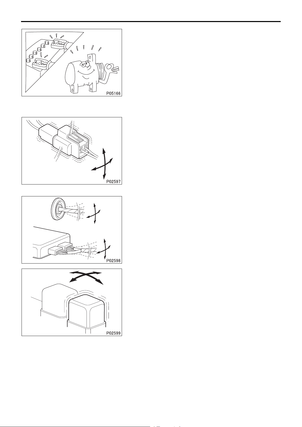
6. Intermittent Faults
• An intermittent fault typically occurs only under certain operating
conditions. Once these conditions have been identified, the
cause of the intermittent fault can be ascertained easily. First,
ask the customer about the vehicle operating conditions and
weather conditions under which the fault occurs. Also ask about
the frequency with which the fault occurs and about the fault
symptoms. Then, reproduce the fault based on this information.
In accordance with the conditions under which the fault occurs,
determine whether the fault is caused by vibration, heat or other
factors. if vibration is a possible factor, see if the fault can be reproduced by performing the following checks on individual connectors and other parts:
• Gently move connectors up and down and to left and right.
• Gently move wiring harnesses up and down and to left and
right.
• Gently wiggle sensors and other devices by hand.
• Gently wiggle wiring harnesses on suspension systems and
other moving parts.
• Connectors and other parts to be checked are those included or
given as likely fault locations in inspection procedures corresponding to diagnosis codes and/or fault symptoms.
00-24
Page 27
00
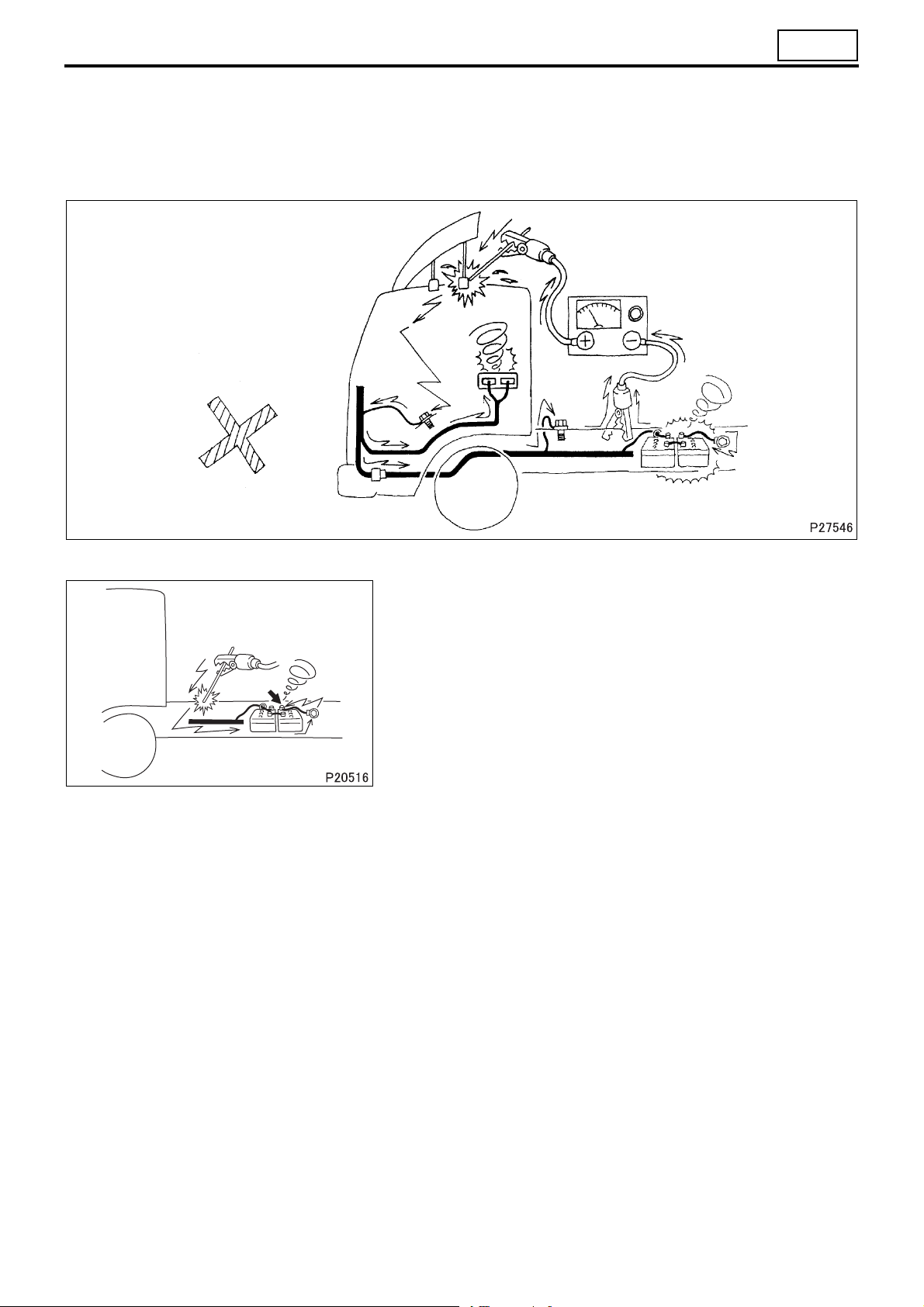
7. Precautions for Arc Welding
• When arc welding is performed, current from the welder flows to ground via the vehicle’s metal parts. Unless ap-
propriate steps are taken, this current can damage control units, other electrical devices and wiring harnesses.
And any electrical device near the point on the vehicle to which the (–) cable of the welder is connected, might be
largely damaged.
• Current flows backward as shown below.
7.1 From battery (–) cable
To prevent damage to the battery and to electrical devices that are
connected directly to the battery, it is essential to disconnect the
battery’s (–) cable.
7.2 Procedure
• Turn the starter switch to the LOCK position.
• Disconnect the battery’s (–) cable.
• Cover all parts of the vehicle that may be damaged by welding
sparks.
• Connect the welder’s (–) cable to the vehicle as close as possible to the area being welded. Do not connect the welder’s (–) cable to the cab if the frame is being welded, and vice versa.
• Set the welding current in accordance with the part being welded.
8. Precautions When Repainting
• When repainting, cover the following electronic control components with a masking material. If paint get on these
components, functional reliability could be deteriorated as a result of the poor connection of connectors, internal
circuit failure caused by heat build-up due to poor heat dissipation, erroneous sensor values due to clogged ventilation holes.
• Engine electronic control unit and other electronic control units
• Sensors
00-25
Page 28
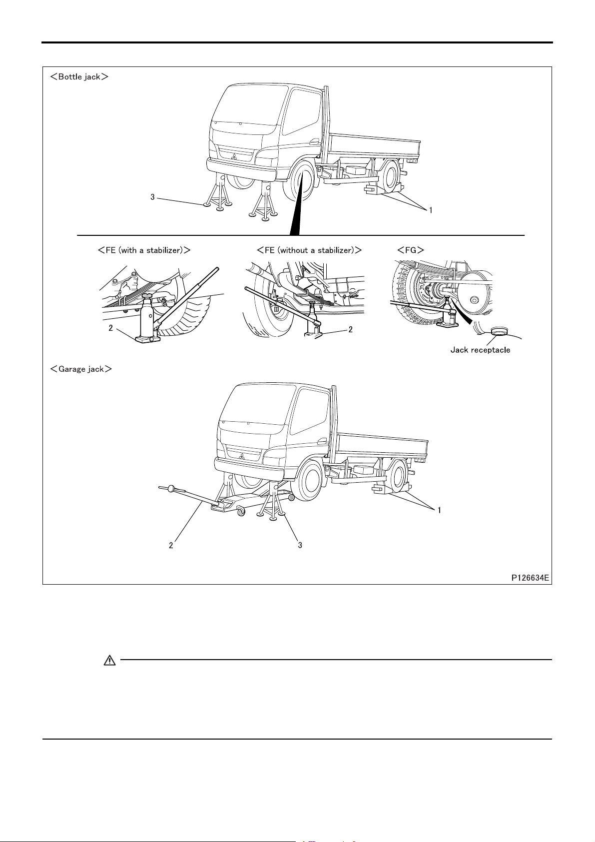
JACKING UP THE VEHICLE
<Front of Vehicle>
Jacking up procedure
1 Place chocks against the rear wheels.
2 Jack up the front of the vehicle with a bottle jack or garage jack.
3 Support the front of the vehicle frame on jack stands.
WARNING
• Chock the wheels firmly to prevent the vehicle from rolling away.
• Do not attempt to remove the chocks until the operation is completed.
• It is extremely dangerous to support the vehicle with only bottle jack or garage jack. Be sure to additionally support the front of the vehicle frame on jack stands.
• Never attempt to remove the bottle jack, garage jack, or jack stands until the operation is completed.
00-26
Page 29
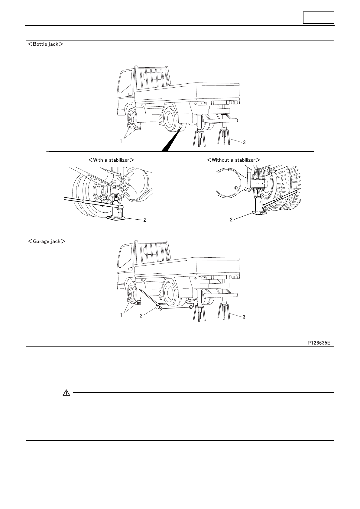
<Rear of Vehicle>
00
Jacking up procedure
1 Place chocks against the front wheels.
2 Jack up the rear of the vehicle using a bottle jack or garage jack as illustrated above.
3 Support the vehicle frame on jack stands on both sides.
WARNING
• Chock the wheels firmly to prevent the vehicle from rolling away.
• Do not attempt to remove the chocks until the operation is completed.
• It is extremely dangerous to support the vehicle with only bottle jack or garage jack. Be sure to additionally support the vehicle frame on jack stands on both sides.
• Never attempt to remove the bottle jack, garage jack, or jack stands until the operation is completed.
00-27
Page 30

DIAGNOSIS CODES
1. Diagnosis Codes
• Diagnosis codes indicate the faulty sections of the vehicle.
• A fault can be repaired by reading out the diagnosis code(s) stored in the control unit and performing the remedy
for that code(s).
• Diagnosis codes can be displayed in the following two methods. Select either of them according to the system to
be diagnosed.
• Using a Multi-Use Tester
• Using flashing of a warning lamp on meter cluster
• The table below indicates the systems for which diagnosis codes can be displayed and the methods usable for in-
dividual systems.
1.1 Systems and diagnosis code displaying methods
Warning lamp System
Anti-lock brake system (ABS) O 35E
Flashing of
warning lamp
1.2 Types of diagnosis codes
(1) Present diagnosis code
• Fault developed in the vehicle after the starter switch is set to ON is indicated by corresponding diagnosis code.
• The fault warning lamp is lit at the same time.
Reference
Gr
(2) Past diagnosis code
• Past fault developed in the vehicle is indicated by corresponding diagnosis code stored in the memory of the elec-
tronic control unit.
• With the vehicle restored to its normal condition or the starter switch turned from OFF to ON after inspection or repair against present diagnosis codes, the present diagnosis code is stored as past diagnosis codes in the memory
of the electronic control unit.
• The warning lamp is not lit because the indicated fault is not present one.
00-28
Page 31

2. Reading and Erasing the Diagnosis Code
2.1 Using a Multi-Use Tester
(1) Connecting a Multi-Use Tester
Special tools
Mark Tool name and shape Part No. Application
FMS-E 12-2
PC
(Multi-Use
Te st er - III version)
Data transmission between V.C.I. and
PC
00
V.C.I. MH062927
Multi-Use Tester harness E
A: For inspection and
drive recorder
B: For drive recorder
C: Driver recorder har-
ness
D: Cigar plug harness
Multi-Use Tester test
harness D
(used for extension)
USB cable MH063668
MH063660
A: MH063662
B: MH063663
C: MH063665
D: MH063666
MH062951
Data transmission between electronic
control unit and PC
Power supply to V.C.I. and communication with electronic control unit
Multi-Use Tester test harness E
extension
Communication between V.C.I. and
PC
00-29
Page 32

DIAGNOSIS CODES
(1.1) To perform system inspection
• Move the starter switch to the LOCK position.
• Connect , , -A and as illustrated.
• Connect the Diagnosis connector on the vehicle with the con-
nector of -A.
(1.2) To use drive recorder function
• Move the starter switch to the LOCK position.
• Connect , , -A, -C, -D
trated.
• Connect the Diagnosis connector on the vehicle with the connector of -C.
• Connect the cigarette lighter plug of -D with the cigarette
lighter socket.
(1.3) To extend the Multi-Use Tester test harness
• Use to extend the cable if -A is not long enough such
as when using Multi-Use Tester outside the vehicle.
and as illus-
(2) Access of diagnosis code
• Set the starter switch to ON.
• Operate the Multi-Use Tester for a display of necessary diagnosis code stored in the memory of the electronic
control unit and identify the location of the fault.
00-30
Page 33

00
(3) Clearing of diagnosis code
• Set the starter switch to ON (the engine not to be started).
• Operate the Multi-Use Tester to delete all the diagnosis codes stored in the memory of the electronic control unit.
2.2 Using flashing of a warning lamp on meter cluster
(1) Anti-lock brake system
• Using the diagnosis and memory clear
switches, display diagnosis codes.
CAUTION
• Opening the memory clear switch
followed by its reconnection will
erase the stored diagnosis codes
from the memory. To avoid inadvertently erasing necessary codes,
be sure to read well the procedure
described below before handling diagnosis codes.
(1.1) Reading diagnosis codes
• To read a diagnosis code, observe how may times the warning
lamp flashes and how long each illumination lasts.
• The duration of illumination differs between the first and second
digits.
• Second digit: 1.2 sec.
• First digit: 0.4 sec.
• A diagnosis code consists of the flashing of second digit and the
flashing of first digit in that order. If a diagnosis code has “0” in
the second digit, only the first digit will be displayed.
• The diagnosis code 01 will be displayed if the system is normal.
• The same diagnosis code will be displayed 3 times in a row be-
fore moving to the display of the next code.
• After the last diagnosis code is displayed, the first code will be
displayed again 3 times in a row and then the subsequent
codes. This will be repeated.
00-31
Page 34

DIAGNOSIS CODES
(1.2) Present diagnosis codes
• Turn the starter switch ON.
• Remove the diagnosis switch.
• Diagnosis codes will be displayed by flashing of the warning
lamp.
• When the diagnosis switch is connected, electronic control unit
will stop (terminate) displaying diagnosis codes.
(1.3) Present and past diagnosis codes
• Turn the starter switch to the ON position.
• Open the diagnosis switch.
• Present diagnosis codes will be displayed by flashing of the
warning lamp.
• Open the memory clear switch.
• Present and past diagnosis codes will be displayed by flashing
of the warning lamp.
• Turn the starter switch to the OFF position and connect the
memory clear switch and diagnosis switch to terminate the diagnosis code displaying mode.
(1.4) Erasing diagnosis codes
• Turn the starter switch to the ON position (do not start the en-
gine).
• Open the memory clear switch and reconnect it; all diagnosis
codes stored in electronic control unit memory will be erased.
To cancel diagnosis code erasure after opening the memory
clear switch, turn the starter switch to the OFF position and then
reconnect the memory clear switch.
00-32
Page 35

M E M O
00
00-33
Page 36

TABLE OF STANDARD TIGHTENING TORQUES
1. Tightening Torques
• Tightening torques are roughly classified into the following two categories:
Tightening torque Definition
Standard tightening
torque
Specified tightening
torque
Tightening torque determined according to thread
size and material of bolts and nuts
Tightening torque of bolts and nuts other than those
defined in “Standard tightening torque”, or that of
bolts and nuts not identified in the following tables
Availability of
torque specifica-
tions in text
None
Provided
• Fasteners used in a location denoted by “wet” should always be tightened in a wet condition (lubricated with engine oil or grease). Any other fasteners than those so specified should be tightened in a dry condition.
2. Table of Standard Tightening Torque
• Threads and bearing surfaces shall be dry (tightened in a dry condition).
• If the mating nut and bolt (or stud bolt) are different in level of strength, tighten them to the torque specified for the
bolt.
• Automotive screws refer to coarse screw thread with nominal diameter of 3 to 8 mm or fine screw thread with
nominal diameter of 10 mm or larger.
How to determine tightening
torque
Locate a bolt or nut corresponding to actual part in the following
standard tightening torque table.
Tightening torque is shown in
the text.
(1) Hexagon head bolts and stud bolts (Unit: N·m {kgf·m})
4T 7T 8T
(stud) (stud) (stud)
Nominal
diameter
mm
M5
M6
M8
M10
M12
M14
M16
M18
M20
M22
M24
Automotive
screw thread
2 to 3
{0.2 to 0.3}
4 to 6
{0.4 to 0.6}
9 to 13
{0.9 to 1.3}
18 to 27
{1.8 to 2.8}
34 to 50
{3.5 to 5.1}
60 to 80
{6.1 to 8.2}
90 to 120
{9.2 to 12}
130 to 170
{13 to 17}
180 to 240
{18 to 24}
250 to 330
{25 to 34}
320 to 430
{33 to 44}
Coarse screw
thread
–
–
–
17 to 25
{1.7 to 2.5}
31 to 45
{3.2 to 4.6}
55 to 75
{5.6 to 7.6}
90 to 110
{9 to 11}
120 to 150
{12 to 15}
170 to 220
{17 to 22}
230 to 300
{23 to 31}
290 to 380
{30 to 39}
Automotive
screw thread
4 to 6
{0.4 to 0.6}
7 to 10
{0.7 to 1.0}
16 to 24
{1.6 to 2.4}
34 to 50
{3.5 to 5.1}
70 to 90
{7.1 to 9.2}
110 to 150
{11 to 15}
170 to 220
{17 to 22}
250 to 330
{25 to 34}
340 to 460
{35 to 47}
460 to 620
{47 to 63}
600 to 810
{61 to 83}
Strength
Coarse screw
thread
–
–
–
32 to 48
{3.3 to 4.9}
65 to 85
{6.6 to 8.7}
100 to 140
{10 to 14}
160 to 210
{16 to 21}
220 to 290
{22 to 30}
310 to 410
{32 to 42}
420 to 560
{43 to 57}
540 to 720
{55 to 73}
Automotive
screw thread
5 to 7
{0.5 to 0.7}
8 to 12
{0.8 to 1.2}
19 to 28
{1.9 to 2.9}
45 to 60
{4.6 to 6.1}
80 to 105
{8.2 to 11}
130 to 170
{13 to 17}
200 to 260
{20 to 27}
290 to 380
{30 to 39}
400 to 530
{41 to 54}
540 to 720
{55 to 73}
700 to 940
{71 to 96}
Coarse screw
thread
–
–
–
37 to 55
{3.8 to 5.6}
75 to 95
{7.6 to 9.7}
120 to 160
{12 to 16}
190 to 240
{19 to 24}
250 to 340
{25 to 35}
360 to 480
{37 to 49}
490 to 650
{50 to 66}
620 to 830
{63 to 85}
00-34
Page 37

Strength
8.8 (Nut 4T) 8.8 (Nut 6T)
Automotive screw thread
Nominal
diameter
mm
M10
M12
M14
18 to 27
{1.8 to 2.8}
34 to 50
{3.5. to 5.1}
60 to 80
{6.1 to 8.2}
45 to 60
{4.6 to 6.1}
80 to 105
{8.2 to 11}
130 to 170
{13 to 17}
(2) Hexagon flange bolts (Unit: N·m {kgf·m})
4T 7T 8T
00
Strength
Nominal
diameter
mm
Nominal
diameter
mm
M6
M8
M10
M12
M10
M12
Automotive
screw thread
4 to 6
{0.4 to 0.6}
10 to 15
{1.0 to 1.5}
21 to 31
{2.1 to 3.2}
38 to 56
{3.9 to 5.7}
8.8 (Nut 4T) 8.8
Automotive screw thread
21 to 31
{2.1 to 3.2}
38 to 56
{3.9 to 5.7}
Coarse screw
thread
20 to 29
{2.0 to 3.0}
35 to 51
{3.6 to 5.2}
Strength
50 to 65
{5.1 to 6.6}
90 to 120
{9.2 to 12}
Automotive
screw thread
–
–
8 to 12
{0.8 to 1.2}
19 to 28
{1.9 to 2.9}
45 to 55
{4.6 to 5.6}
80 to 105
{8.2 to 11}
Coarse screw
thread
–
–
37 to 54
{3.8 to 5.5}
70 to 95
{7.1 to 9.7}
Automotive
screw thread
10 to 14
{1.0 to 1.4}
22 to 33
{2.2 to 3.4}
50 to 65
{5.1 to 6.6}
90 to 120
{9.2 to 12}
Coarse screw
thread
–
–
50 to 60
{5.1 to 6.1}
85 to 110
{8.7 to 11}
00-35
Page 38

TABLE OF STANDARD TIGHTENING TORQUES
(3) Hexagon nuts (Unit: N·m {kgf·m})
Strength
4T 6T (Bolt 7T) 6T (Bolt 8T)
Nominal
diameter
mm
M5
M6
M8
M10
M12
M14
M16
M18
M20
M22
M24
Automotive
screw thread
2 to 3
{0.2 to 0.3}
4 to 6
{0.4 to 0.6}
9 to 13
{0.9 to 1.3}
18 to 27
{1.8 to 2.8}
34 to 50
{3.5 to 5.1}
60 to 80
{6.1 to 8.2}
90 to 120
{9.2 to 12}
130 to 170
{13 to 17}
180 to 240
{18 to 24}
250 to 330
{25 to 34}
320 to 430
{33 to 44}
Coarse screw
thread
–
–
–
17 to 25
{1.7 to 2.5}
31 to 45
{3.2 to 4.6}
55 to 75
{5.6 to 7.6}
90 to 110
{9 to 11}
120 to 150
{12 to 15}
170 to 220
{17 to 22}
230 to 300
{23 to 31}
290 to 380
{30 to 39}
Automotive
screw thread
4 to 6
{0.4 to 0.6}
7 to 10
{0.7 to 1.0}
16 to 24
{1.6 to 2.4}
34 to 50
{3.5 to 5.1}
70 to 90
{7.1 to 9.2}
110 to 150
{11 to 15}
170 to 220
{17 to 22}
250 to 330
{25 to 34}
340 to 460
{35 to 47}
460 to 620
{47 to 63}
600 to 810
{61 to 83}
Coarse screw
thread
–
–
–
32 to 48
{3.3 to 4.9}
65 to 85
{6.6 to 8.7}
100 to 140
{10 to 14}
160 to 210
{16 to 21}
220 to 290
{22 to 30}
310 to 410
{32 to 42}
420 to 560
{43 to 57}
540 to 720
{55 to 73}
Automotive
screw thread
5 to 7
{0.5 to 0.7}
8 to 12
{0.8 to 1.2}
19 to 28
{1.9 to 2.9}
45 to 60
{4.6 to 6.1}
80 to 105
{8.2 to 11}
130 to 170
{13 to 17}
200 to 260
{20 to 27}
290 to 380
{30 to 39}
400 to 530
{41 to 54}
540 to 720
{55 to 73}
700 to 940
{71 to 96}
Coarse screw
thread
–
–
–
37 to 55
{3.8 to 5.6}
75 to 95
{7.6 to 9.7}
120 to 160
{12 to 16}
190 to 240
{19 to 24}
250 to 340
{25 to 35}
360 to 480
{37 to 49}
490 to 650
{50 to 66}
620 to 830
{63 to 85}
(4) Hexagon flange nuts (Unit: N·m {kgf·m})
Strength
4T
Nominal
diameter
mm
M6
M8
M10
M12
Automotive
screw thread
4 to 6
{0.4 to 0.6}
10 to 15
{1.0 to 1.5}
21 to 31
{2.1 to 3.2}
38 to 56
{3.9 to 5.7}
Coarse screw
thread
–
–
20 to 29
{2.0 to 3.0}
35 to 51
{3.6 to 5.2}
(5) Tightening torques of general flare nuts (Unit: N·m {kgf·m})
Pipe diameter mm
Tightening torque 17 {1.7} 25 {2.6} 39 {4.0} 59 {6.0} 88 {9.0} 98 {10}
φ4.76 φ6.35 φ8 φ10 φ12 φ15
00-36
Page 39

(6) Tightening torques of nylon tubes for general air piping (DIN) (Unit: N·m {kgf·m})
Nominal diameter
× wall thickness mm
Tightening torque 20 {2.0 } 34 {3.5 } 49 {5.0 } 54 {5.5 }
6 × 1 10 × 1.25 12 × 1.5 15 × 1.5
+60+0.6
0
+10
+1.0
0
0
+10
+1.0
0
0
+50+0.5
(7) Tightening torques of nylon tubes for general air piping (SAE) (Unit: N·m {kgf·m})
Nominal diameter in. 1/4 3/8 1/2 5/8
Tightening torque 13 {1.3 } 29 {3.0 } 49 {5.0 } 64 {6.5 }
+40+0.4
0
+50+0.5
+5
0
+0.5
0
0
+50+0.5
00
0
0
00-37
Page 40

Page 41

GROUP 11 ENGINE
SPECIFICATIONS ................................................................................11-2
STRUCTURE AND OPERATION
1. Exploded View...............................................................................11-3
2. Valve Mechanism...........................................................................11-4
3. Cylinder Head Gasket <4D34> .......................................................11-5
4. Water Director................................................................................11-5
5. Connecting Rod.............................................................................11-5
6. Piston ............................................................................................11-6
7. Timing Gears .................................................................................11-6
TROUBLESHOOTING .........................................................................11-7
ON-VEHICLE INSPECTION AND ADJUSTMENT
1. Measuring Compression Pressure.................................................11-8
2. Inspection and Adjustment of Valve Clearances ..........................11-10
ENGINE REMOVAL AND INSTALLATION
<TILT CAB>......................................................................................11-12
<FIXED CAB>...................................................................................11-16
CYLINDER HEAD ..............................................................................11-18
PISTON AND CONNECTING ROD, CYLINDER SLEEVE................11-34
FLYWHEEL ........................................................................................11-48
TIMING GEARS .................................................................................11-52
CAMSHAFT........................................................................................11-56
CRANKSHAFT AND CRANKCASE ..................................................11-60
CAMSHAFT BUSHINGS....................................................................11-70
11-1
Page 42

SPECIFICATIONS
Item Specifications
Engine model 4D33 4D34T4
Type 4-cylinder, in-line, water-cooled, 4-cycle diesel engine
Combustion chamber Direct injection type
Valve mechanism Overhead valves
Maximum output kW {PS} /rpm 83 {120} /3200 100 {139} /2900
Maximum torque N·m {kgf·m} /rpm 304 {31} /1800 373 {38} /1600
Bore × stroke mm φ108 × 115 φ104 × 115
3
Total displacement cm
Compression ratio 18 18.5
Remarks
Output and torque represent performance of run-in engine operating under the standard ambient conditions and
accessories specified below.
Standard
JIS JIS D1004, 1976
EEC EEC 595/2009
{760 mmHg}, dry
{743 mmHg}, dry
{L} 4214 {4.214} 3907 {3.907}
Barometric
pressure
101.3 kPa
99 kPa
Temperature of
inlet air
15.0°C Fan, Air cleaner
25.0°C
Fan, Intake and exhaust
system of vehicle
Accessories
11-2
Page 43

STRUCTURE AND OPERATION
1. Exploded View
11
11-3
Page 44

STRUCTURE AND OPERATION
2. Valve Mechanism
• Each valve has a valve stem seal,
which regulates the flow of lubricating
oil to the contact surface between the
valve and the valve guide.
• The outer valve springs are variablepitch springs.
• The valve clearance is adjusted using
an adjusting screw.
11-4
Page 45

3. Cylinder Head Gasket <4D34>
4. Water Director
11
• Select and use a cylinder head gasket
of a thickness that can accommodate
the piston projection.
• The size (thickness) class of the gasket can be identified by the shape of
the notches cut on the edge of each
gasket.
• The water director is attached to the
bottom surface of the cylinder head,
and is used to direct the flow of the
coolant in the right direction.
5. Connecting Rod
11-5
Page 46

STRUCTURE AND OPERATION
6. Piston
7. Timing Gears
• Each gear has one or two alignment marks (“1”, “2”, “3”) to facilitate reassembly.
11-6
Page 47

TROUBLESHOOTING
11
Symptoms
Reference Gr
Possible causes
Incorrect valve clearance O O
Defective cylinder head gasket O O
Cylinder head and valve
mechanism
Timing gears
Camshaft
Pistons and connecting
rods
Crankshaft
Fuel system
Cooling system
Intake and exhaust
system
Incorrect oil viscosity O Gr12
Improper fuel O
Incorrectly fitted piping and hoses O
Defective/incorrectly fitted alternator and other auxiliaries O
Worn valve and valve seat; carbon deposits O O
Weakened valve spring O O
Defective rocker shaft and bracket O
Poor lubrication of rocker shaft bracket O
Worn tappet O
Incorrect backlash in timing gears O
Poor lubrication of timing gears and idler shaft O
Excessive end play in camshaft O
Worn camshaft O
Worn/damaged piston ring groove(s) O O
Worn/damaged piston ring(s) O O
Worn piston pin and connecting rod small end O
Excessive end play in crankshaft O
Incorrectly fitted crankshaft O
Worn/damaged crankshaft pins and connecting rod bearings
Worn/damaged crankshaft journals and main bearings O
Injection timing faulty O O
Defective injection pump O O
Faulty fuel spray from injection nozzle O O
Air trapped in fuel system O
Malfunctioning cooling system components O
Loose/damaged V-belts O
Clogged air cleaner O O
Clogged muffler O O
Low power output
Abnormal engine noise
O
Gr13
Gr14
Gr15
11-7
Page 48

ON-VEHICLE INSPECTION AND ADJUSTMENT
1. Measuring Compression Pressure
Service standards
Location Maintenance item Standard value Limit Remedy
2550 kPa
{26 kgf/cm
–
2
}
– Compression pressure
Each cylinder (at 200 rpm)
Cylinder-to-cylinder pressure difference
Special tools (Unit: mm)
Mark Tool name and shape Part No. Application
1960 kPa
{20 kgf/cm2}
390 kPa
{4 kgf/cm
2
or less
Inspect
}
Inspect
Compression gauge
adapter
A
M14 × 1.5
MH061460 Measuring compression pressure
• A drop in compression pressure can be used as a guide to determine when the engine should be overhauled.
• Measure the compression pressure at regular intervals. Keeping track of its transitions can provide a useful tool
for troubleshooting. On new vehicles and vehicles with newly replaced parts, the compression pressure will be
somewhat higher depending on the break-in condition of piston rings, valve seats, etc., but this will return to normal as the parts wear down.
• Before the compression measurement, confirm that the engine oil, starter, and battery are in normal condition.
• Place the vehicle in the following conditions.
• Warm up the engine until the coolant temperature reaches approximately 75 to 85°C.
• Turn off the lights and auxiliaries.
• Place the transmission in neutral.
• Place the steering wheel in the straight-ahead position.
• Disconnect the connector of the fuel-cut motor so that no injec-
tion of fuel takes place when turning over the engine using the
starter.
11-8
• Remove all injection nozzles.
• Cover the injection nozzle mounting holes with shop towels.
• After cranking the engine with the starter, check that no foreign
substances are deposited on the shop towels.
• If there are deposits (such as engine oil or coolant) on the shop
towels, the following may be the cause:
• Deposits of engine oil alone can mean a defective piston ring
seal; the piston rings must be inspected.
• Deposits of both engine oil and coolant can mean cracks in
the cylinders; the crankcase must be replaced.
Page 49

11
WARNING
• When coolant and engine oil deposits are evident, cranking
the engine could be dangerous as these substances, heated to high temperatures, will blow out from the injection
nozzle mounting holes. Make sure to stay away from the injection nozzle mounting holes when the engine is being
cranked.
• Attach the gasket and to one of the injection nozzle mount-
ing holes and fix it in place with the nozzle bridge. Then, connect
a compression gauge to .
• Crank the engine and measure the compression pressure for all
the cylinders one after another. Determine the compression
pressure difference between the cylinders.
• If the compression pressure is below the limit or the cylinder-tocylinder pressure differences is not within the limit, pour a small
amount of engine oil into the corresponding injection nozzle
mounting hole and remeasure the compression pressure.
• If the compression pressure increases, the piston rings and
cylinder surfaces may be badly worn or otherwise damaged.
• If the compression pressure remains unchanged, there may
be seizure in the valves, the valves may be incorrectly seated
or the cylinder head gasket may be defective.
11-9
Page 50

ON-VEHICLE INSPECTION AND ADJUSTMENT
2. Inspection and Adjustment of Valve Clearances
Service standards (Unit: mm)
Location Maintenance item Standard value Limit Remedy
– Valve clearance (when cold) 0.4 – Adjust
Special tools (Unit: mm)
Mark Tool name and shape Part No. Application
Cranking handle
A
36
Slotted screwdriver MH060008
MH061289 For cranking the engine
• Valve clearances should be checked and adjusted as follows
while the engine is still cold.
[Inspection]
• Remove the rocker cover.
• Bring the No. 1 or No. 4 cylinder piston to the top dead center
(TDC) on the compression stroke according to the following procedure:
• Rotate the crankshaft pulley in the illustrated direction so that
the pointer is aligned with the “0” mark next to the “1” to “4”
mark on the inscribed scale on the crankshaft pulley. Either
one of the two pointers can be used for this purpose.
• This will place either the No. 1 or No. 4 cylinder piston at TDC
on the compression stroke. The cylinder in which the rocker
arms for both the intake and exhaust valves can be pushed
down by hand by the valve clearance amounts has its piston
at TDC. Rotate the engine by one full turn to switch the TDCs
of the No. 1 and No. 4 cylinder pistons.
For adjusting valve clearance (when
engine is mounted on vehicle)
11-10
• With the No. 1 or No. 4 cylinder piston at TDC, measure the
clearance of the valves marked with a circle in the table below.
• The feeler gauge must have a slight drag when taking measurements. If the feeler gauge can be moved without any resistance,
the measurement will be incorrect.
Cylinder No. 1 2 3 4
Valve INEXINEXINEXINEX
No. 1 cylinder piston at
TDC on compression
stroke
No. 4 cylinder piston at
TDC on compression
stroke
OOO – –O – –
–––OO–OO
• If the measurements are not within the standard value range,
adjust the value clearance via the following procedures.
Page 51

11
[Adjustment]
• Adjust the valve clearance by loosening the lock nut and rotating
the adjusting screw so that the feeler gauge can only be moved
with a slight drag.
• After the adjustment, hold the adjusting screw in position with a
screwdriver and tighten the lock nut to the specified torque.
• Recheck the valve clearance with the feeler gauge, and readjust
if the measurements are not within the specified value range.
• When carrying out valve clearance adjustment with the engine
still mounted on the vehicle, use to facilitate rotation of the
adjusting screw.
11-11
Page 52

ENGINE REMOVAL AND INSTALLATION <TILT CAB>
<FE>
WARNING
• Only use hoisting equipment appropriate for the engine weight (approximately 500 kg).
Tightening torque (Unit: N·m {kgf·m})
Mark Parts to be tightened Tightening torque Remarks
Bolt (front mounting installation) 50 to 65 {5.1 to 6.6} –
Bolt (rear mounting installation) 130 to 170 {13 to 17} –
11-12
Page 53

Removal procedure
11
Removal: Engine and transmission
• Hook the wire rope and lifting mechanism each onto the two
hangers on the engine and lift the engine with a crane until they
are tight.
• Support the transmission with the transmission jack.
• Check that all wiring and piping have been disconnected from
the engine.
• Taking care not to let the transmission back plate hit the engine
rear support, first push down the transmission part of the assembly, and then move the engine and transmission assembly forward.
• Once the transmission is out of the front end of the rear body,
turn the engine and transmission assembly 90° to the right so as
to prevent the assembly from hitting the frame and cab, and lower it to the right side of the vehicle. Make fine adjustments to the
hoisting equipment as necessary.
11-13
Page 54

ENGINE REMOVAL AND INSTALLATION <TILT CAB>
<FG>
Removal sequence
1 Roll stopper
2 Transmission
3 Engine
Installation sequence
Follow the removal sequence in reverse.
CAUTION
• Be careful not to let the engine hit the cab or the rear body when hoisting the engine.
• Only use hoisting equipment appropriate for the engine weight (approximately 500 kg).
Tightening torque (Unit: N·m {kgf·m})
Mark Parts to be tightened Tightening torque Remarks
Bolt (front mounting installation) 50 to 65 {5.1 to 6.6} –
Bolt (roll stopper bracket installation)
Bolt (rear mounting installation)
Bolt (transmission installation) 47 {4.8} M10 × 1.25
Bolt (transmission installation) 82 {8.4} M12 × 1.75
45 to 65 {4.5 to 6.5} –
11-14
Page 55

Removal procedure
11
Removal: Engine
• Hook the wire rope and lifting mechanism each onto the two
hangers on the engine and lift the engine with a crane until they
are tight.
• Support the transmission with the transmission jack.
• Check that all wiring and piping have been disconnected from
the engine.
• Hoist the engine slowly, taking care not to let the engine hit the
frame and the cab.
• Once the bottom of the engine is out of the frame, turn the engine by 90° and remove it out of the vehicle.
11-15
Page 56

ENGINE REMOVAL AND INSTALLATION <FIXED CAB>
Removal sequence
1 Roll stopper
2 Engine and transmission
Installation sequence
Follow the removal sequence in reverse.
CAUTION
• Before removing each part, support the engine and transmission assembly in place using an engine lifter
and a transmission jack.
Tightening torque (Unit: N·m {kgf·m})
Mark Parts to be tightened Tightening torque Remarks
Bolt (front mounting installation) 50 to 65 {5.1 to 6.6} –
Bolt (rear mounting installation) 130 to 170 {13 to 17} –
Bolt (roll stopper bracket mounting)
Bolt (rear mounting installation)
45 to 65 {4.5 to 6.5} –
11-16
Page 57

Removal procedure
11
Removal: Engine and transmission
• Support the engine and transmission with an engine lift and a
transmission jack.
• Check that all wiring and piping have been disconnected from
the engine.
• Lower the engine and transmission to the greatest extent possible while keeping it horizontally balanced.
• Jack up the vehicle and slide the engine and transmission forward.
11-17
Page 58

CYLINDER HEAD
Disassembly sequence
1 Oil filler cap
2 Plate
3 Insulator
4 Rocker cover
5 Rocker cover gasket
6 Cylinder head bolt
7 Rocker and bracket assembly
(See later sections.)
8 Push rod
9 Cylinder head
(See later sections.)
10 Cylinder head gasket
11 Tappet
a: Crankcase
*
: Locating pin
: Non-reusable parts
Assembly sequence
Follow the disassembly sequence in reverse.
CAUTION
• Be careful not to damage the glow plugs and injection nozzles when placing the cylinder head on the
worktable, as they protrude out of the bottom of the cylinder head.
• The cylinder head bolts are tightened using the torque-turn method. Any cylinder head bolt that has three
marks indicating that the bolt has been tightened three times already must be replaced with a new one.
Service standards (Unit: mm)
Location Maintenance item Standard value Limit Remedy
8 Push rod run-out – 0.4 Replace
a Tappet-to-tappet hole clearance 0.05 to 0.09 0.2 Replace
11,
*
Tightening torque (Unit: N·m {kgf·m})
Mark Parts to be tightened Tightening torque Remarks
Bolt (rocker cover mounting) 3 to 4 {0.3 to 0.4} –
Cylinder head bolt 150 {15} +90°
• Wet
• Reusable up
to 3 times
Lubricant and/or sealant
Mark Points of application Specified lubricant and/or sealant Quantity
Threads of cylinder head bolt
Engine oil As requiredUpper and lower ends of push rod
Outer surface of tappet
11-18
Page 59

Special tools
Mark Tool name and shape Part No. Application
Socket wrench MH061560 Installation of cylinder head
Tappet extractor MH063329 Removal of tappet
Work before removal
Preparing for cylinder head removal: Releasing valve spring
tension
• If the rocker arms are pressing down on the valve springs, loos-
en the adjusting screws on the rocker arms before loosening the
cylinder head bolts to prevent any damage by the valve springs’
tension.
11
Removal procedure
Removal: Cylinder head
• To remove the cylinder head, first loosen the cylinder head bolts
in the order indicated in the illustration.
Removal: Cylinder head gasket
CAUTION
• Be careful not to scratch the cylinder head and crankcase
when removing the cylinder head gasket.
Removal: Tappets
11-19
Page 60

CYLINDER HEAD
Inspection procedure
Inspection: Push rod run-out
• If the measured values exceed the limit, replace the push rod.
Inspection: Tappet-to-tappet hole clearance
• If the measured values exceed the limit, replace the defective
part(s).
Installation procedure
Installation: Cylinder head gasket
<4D33>
• Install the cylinder head gasket on the crank case in the illustrat-
ed direction.
<4D34>
• The cylinder head gasket comes in three sizes. Choose the gas-
ket appropriate for the cylinder head by the following procedure.
• Measure the amount of piston projection for every cylinder.
(See the PISTON AND CONNECTING RODS section.)
CAUTION
• Replacement of the piston or connecting rod alters the piston projection. Always measure the amount of piston projection after either or both of them are replaced.
11-20
Page 61

11
• Select a cylinder head gasket with the appropriate thickness
for the measured maximum piston projection value from the
following table.
If any of the piston projection measurements is more than
0.05 mm larger than the average value, then use a gasket
that is a rank thicker (A→B, B→C).
Piston projection Cylinder head gasket
Average value of
piston projection
0.466 to 0.526 A 1.35 ± 0.03
0.526 to 0.588 B 1.40 ± 0.03
0.588 to 0.648 C 1.45 ± 0.03
• The size class of the cylinder head gasket can be determined
from the shape of the notches cut on the gasket edge.
• Install the cylinder head gasket on the crankcase in the illustrated direction.
Installation: Cylinder head
Size
CAUTION
• Before fitting the cylinder head bolts, check the punch
marks on each bolt’s head. Do not use the bolt if there are
three punch marks.
• The punch marks indicate the number of times each bolt
has been tightened using the torque-turn tightening method. Any bolt that already has three punch marks must be replaced.
Thickness when
tightened
• Tighten the bolts to half the specified torque (75 N·m {7.5 kgf·m})
in the order indicated in the illustration.
• Tighten these bolts further to the specified torque (150 N
·m}) in the same order, then completely tighten them by the
kgf
following procedure.
: Bolts also fastening rocker arm and bracket assembly
• Turn the holder of counterclockwise to pretension the inter-
nal spring.
·m {15
11-21
Page 62

CYLINDER HEAD
• Fit on the bolt and set it so that the rod (extension) is held
pressed by the spring force against a surrounding part such as
the rocker shaft bracket or the injection pipe.
• Select a clearly visible mark on the scale on the holder.
• Use this mark as a point of reference and turn the socket clock-
wise 90° (one graduation on the socket scale represents 5°).
• After tightening each bolt, make a punch mark on the head of
the bolt to indicate the number of times that it has been used
(bolts may not be used more than three times).
CAUTION
• Cylinder head bolts that have been tightened using the
torque-turn method must never be additionally tightened after the final angular tightening.
11-22
Page 63

M E M O
11
11-23
Page 64

CYLINDER HEAD
Rocker and Bracket
Disassembly sequence
1 Set bolt
2 Rocker shaft bracket
3 Adjusting screw
4 Rocker bushing
5 Intake valve rocker
6 Rocker shaft spring
7 Exhaust valve rocker
8 Rocker shaft
: Non-reusable parts
Assembly sequence
Follow the disassembly sequence in reverse.
Service standards (Unit: mm)
Location Maintenance item Standard value Limit Remedy
4, 8 Rocker bushing-to-rocker shaft clearance 0.06 to 0.11 0.2 Replace
Lubricant and/or sealant
Mark Points of application Specified lubricant and/or sealant Quantity
Rocker bushing inside surface Engine oil As required
Special tools (Unit: mm)
Mark Tool name and shape Part No. Application
Rocker bushing puller
AB
φ19 φ21
Inspection procedure
MH061378
Inspection: Rocker bushing-to-rocker shaft clearance
• If the difference between the measurements exceeds the limit,
replace the bushing.
Removal and installation of rocker
bushing
11-24
Page 65

11
Replacement of rocker bushing
[Removal]
[Installation]
• Assemble the tool and parts as illustrated while aligning the oil
hole in the bushing and the oil hole in the rocker.
• Force the bushing into the rocker until touches the rocker’s
chamfered end.
• After the installation is completed, measure the clearance between the rocker shaft and the bushing.
• If the measurement is less than the minimum value in the standard value range, ream the rocker bushing.
Installation procedure
Installation: Rocker shaft
• Install the rocker shaft with its ends facing in the illustrated direc-
tions.
11-25
Page 66

CYLINDER HEAD
Cylinder Head
Disassembly sequence
1 Valve cap
2 Valve cotter
3 Upper retainer
4 Outer valve spring
5 Valve stem seal
6 Intake valve
7 Exhaust valve
8 Nozzle bridge
9 Injection nozzle (See Gr13.)
10 O-ring
11 Nozzle tip gasket
12 Intake valve guide
13 Exhaust valve guide
14 Intake valve seat
15 Exhaust valve seat
16 Water director
17 Cylinder head
: Non-reusable parts
Assembly sequence
Follow the disassembly sequence in reverse.
CAUTION
• When an intake valve or exhaust valve has been removed, make sure to replace the valve stem seal.
Service standards (Unit: mm)
Location Maintenance item Standard value Limit Remedy
Free length 68.3 63.0
4 Outer valve spring
6 Intake valve
6, 12 Intake valve stem-to-valve guide clearance 0.04 to 0.06 0.15 Replace
Installed load
(47.80 in installed length)
Squareness – 2.5
Stem outside diameter 8.96 to 8.97 8.85 Replace
Sinkage from cylinder head bottom surface
Valve margin 1.5 1.2
Seat angle 45° ± 15’ –
390 ± 20 N
{40 ± 2.0 kgf}
1.0 ± 0.25 1.5 Inspect
348 N
{35.5 kgf}
Replace
Reface or replace
11-26
Page 67

Location Maintenance item Standard value Limit Remedy
Stem outside diameter 8.93 to 8.94 8.85 Replace
Sinkage from cylinder
7 Exhaust valve
7, 13 Exhaust valve stem-to-valve guide clearance 0.07 to 0.1 0.2 Replace
Intake valve seat
14
width
15 Exhaust valve seat width 2.0 ± 0.2 2.8
17 Cylinder head
head bottom surface
Valve margin 1.5 1.2
Seat angle 45° ± 15’ –
4D33 2.0 ± 0.2 2.8
4D34 2.8 ± 0.2 3.6
Bottom surface distortion 0.05 or less 0.2
Height from top surface to bottom
surface
1.2 ± 0.25 1.7 Inspect
Reface or replace
Correct or
replace
Correct or
replace
Correct or
replace
95 ± 0.1 94.6 Replace
Tightening torque (Unit: N·m {kgf·m})
Mark Parts to be tightened Tightening torque Remarks
Bolt (nozzle bridge installation) 25 {2.5} –
11
Lubricant and/or sealant
Mark Points of application Specified lubricant and/or sealant Quantity
Contact surfaces between valve cap and rocker
Lip of valve stem seal
Val v e ste m
O-ring
Engine oil As required
Special tools (Unit: mm)
Mark Tool name and shape Part No. Application
Val ve li fter
A
φ42
Valve lifter hook MH061679
MH061668
Removal and installation of valve
cotters
Valve stem seal installer
AB
φ28 φ9
MH061293 Installation of valve stem seals
11-27
Page 68

CYLINDER HEAD
Mark Tool name and shape Part No. Application
Valve lapper 30091-07500 Lapping valves and valve guides
Valve guide remover
AB
φ9 φ13
Valve guide installer
ABC
φ28.5 φ15 φ18
Caulking
tool body
Caulking ring
Model B
Intake
Exhaust
4D33 φ 49
4D34 φ 47.6
4D33 φ 42
4D34 φ 40.6
φ9
MH061066 Removal of valve guides
MH061998 Installation of valve guides
A
MH061067
<Intake
(4D33)>
MH061695
<Intake
(4D34)>
MH061275
<Exhaust
(4D33)>
MH061696
<Exhaust
(4D34)>
MH061069
Installation of valve seat
Removal procedure
11-28
Removal: Valve cotters
• Remove the valve cotters by evenly compressing the valve
springs.
CAUTION
• Do not compress the valve springs more than necessary, as
this may cause the upper retainer to touch the valve stem
seal and damage it.
Page 69

Inspection procedure
11
Inspection: Valve stem outside diameter
• Replace the valve if the stem’s outside diameter is below the lim-
it or is severely worn.
• When the valve has been replaced with a new one, make sure to
lap the valve and valve seat.
Inspection: Valve seat angle and valve margin
• Reface or replace the valve if the valve seat angle or valve mar-
gin exceeds the specified limits.
Refacing
• Limit grinding to a necessary minimum.
• If the valve margin is below the limit after grinding, replace the
valve.
• After grinding, make sure to lap the valve and valve seat.
Inspection: Valve-to-valve guide clearance
• If the clearance exceeds the specified limit, replace the defective
part(s).
Replacement of valve guides
[Removal]
11-29
Page 70

CYLINDER HEAD
[Installation]
• Install the valve guide until sits snugly on the cylinder head.
CAUTION
• The valve guides must be pressed to a depth of 10 mm. Be
sure to use for this operation.
• Exhaust valve guides are longer than intake valve guides.
Make sure to install the correct type of guide in each location.
Inspection: Contact between valve and valve seat
• Before starting inspection, check that the valve and valve guide
are intact.
• Apply an even coat of red lead to the valve contact surface of
the valve seat.
• Strike the valve once against the valve seat. Do not rotate the
valve during this operation.
• If the red lead deposited on the valve indicates a poor contact
pattern, take either of the following corrective actions.
Corrective action
Minor defect Lapping
Serious defect Reface or replace valve and valve seat
Lapping
• Apply a thin coat of lapping compound to the seat contact sur-
face of the valve.
• Start with an intermediate-grit compound (120 to 150 grit) and
finish with a fine-grit compound (200 grit or more).
• Adding a small amount of engine oil to the lapping compound
can facilitate even application.
CAUTION
• Do not put any compound on the stem.
• Strike the valve several times against the valve seat while rotat-
ing the valve a little at a time.
• Wash away the compound with diesel fuel.
• Apply engine oil to the valve contact surface of the valve seat
and rub in the valve and seat well.
• Inspect the contact pattern of the valve and valve seat again.
• If the contact pattern is still defective, replace the valve seat.
11-30
Page 71

11
Inspection: Valve seats
(1) Valve seat width
• If the measurement exceeds the limit, reface or replace the
valve seat.
• After refacing or replacing the valve seat, make sure to lap the
valve seat and valve.
(2) Valve sinkage from cylinder head bottom surface
• Perform measurement keeping the valve in close contact with
the valve seat.
• If the measurement exceeds the limit, adjust or replace the defective part(s).
Refacing the valve seat
• Grind the valve seat using a valve seat cutter or valve seat
grinder.
• Place a piece of sandpaper of approximately #400 between the
cutter and valve seat and grind the valve seat lightly.
• Use a 15° or 75° cutter to cut the valve seat to a width within the
standard range.
CAUTION
• Make sure that the valve seat refacing does not cause the
valve sinkage to exceed the specified limit.
• Lap the valve and valve seat.
Replacement of valve seat
[Removal]
• The valve seats are installed by expansion fitting. To remove a
valve seat, grind inside the metal stock to reduce the wall thickness, then remove the valve seat at room temperature.
11-31
Page 72

CYLINDER HEAD
[Installation]
• Check that the diameters of the intake and exhaust valve seat
holes A and B in the cylinder head conform with the values
shown below.
4D33 4D34
Intake valve seat hole: A
Exhaust valve seat hole: B
+0.025
φ50 mm φ46 mm
0
+0.025
φ43 mm φ39 mm
0
+0.025
0
+0.025
0
• Replace the cylinder head if necessary.
• Chill the valve seat thoroughly by immersing in it in liquid nitro-
gen.
CAUTION
• Handle the chilled valve seats extremely carefully to avoid
getting frostbite.
• Install the valve seat in the cylinder head using and .
• Lap the valve seat and valve.
Installation procedure
Inspection: Cylinder head bottom surface distortion
• If the distortion exceeds the specified limit, rectify it using a sur-
face grinder.
CAUTION
• Make sure that the height of the cylinder head from the top
surface to the bottom surface is not reduced to a value below the specified limit.
Installation: Water director
• Install the water director to the specified depth (4 mm) with the
notch facing in the illustrated direction.
11-32
Installation: Valve stem seal
• Apply engine oil to the lip of the valve stem seal.
• Install the valve stem seal until sits snugly on the cylinder
head.
• After installing the valve stem seal, check that its spring is not
deformed or damaged. Replace the valve stem seal if the spring
is defective.
Page 73

11
Installation: Valve cotter
• To install the valve cotter, follow the removal procedure. (See
“ Removal: Valve cotter”.)
11-33
Page 74

PISTON AND CONNECTING ROD, CYLINDER SLEEVE
Disassembly sequence
1 Lower connecting rod bearing
2 Connecting rod cap
3 Upper connecting rod bearing
4 Piston and connecting rod
(See later sections.)
5 Cylinder sleeve <4D34>
Cylinder sleeve for correction <4D33>
: Non-reusable parts
a: Crankcase
*
Assembly sequence
Follow the disassembly sequence in reverse.
CAUTION
• The connecting rod bolts are fastened using the torque-turn method. Any connecting rod bolt that has
three marks indicating that it has been tightened three times already must be replaced with a new bolt together with its nut.
• The cylinder sleeve for correction is not installed at the first overhaul. The sleeve is used when correction
is needed. <4D33>
Service standards (Unit: mm)
Location Maintenance item Standard value Limit Remedy
Piston projection from
–
crankcase top surface
(average value)
– Connecting rod end play 0.15 to 0.45 0.6 Inspect
Span when
1, 3
Connecting rod
bearing
free
Oil clearance
4D33 0.57 to 0.83
4D34 0.53 to 0.77
4D33 –
4D34 –
4D33 0.035 to 0.094 0.2
4D34 0.04 to 0.099 0.2
– Inspect
Less than
64.5
Less than
69.5
Replace
11-34
Page 75

11
Location Maintenance item Standard value Limit Remedy
Correct or re-
place with over-
sized ones
Correct, replace
with oversized
ones or install
cylinder sleeve
for correction
Correct or re-
place with over-
sized ones
CorrectOut-of-roundness 0.01 or Less –
Replace with
oversized ones
Replace
4, 5
4, *a
5
5,
*
Piston and connecting rod-to-cylinder sleeve clearance
<4D34>
Clearance between piston and connecting rod
assembly and crankcase cylinder <4D33>
Bore diameter φ102.8 to 103 φ103.25
Cylinder sleeve
<4D34>
Crankcase cylinder or cylinder
sleeve for correction <4D33>
Interference between cylinder sleeve for correction and
a
crankcase <4D33>
*
Interference between cylinder
sleeve and
crankcase
<4D34>
Crankcase
sleeve hole
(when cylinder
a
sleeve for correction is installed) <4D33>
Out-of-roundness 0.01 or Less –
Taper 0.03 or Less –
Bore diameter φ108 to 108.03 φ108.25
Taper 0.03 or Less –
Standard 0.17 to 0.23 –
Oversize 0.19 to 0.21 – Replace
Bore diameter φ111.18 to 111.21 –
Out-of-roundness 0.01 or Less –
Taper 0.03 or Less –
0.115 to 0.525 –
Basic diameter : 108
0.07 to 0.12
0.21 to 0.27 – Replace
–
Tightening torque (Unit: N·m {kgf·m})
Mark Parts to be tightened Tightening torque Remarks
Nut (connecting rod cap installation) 68.6 {7.0} + 90
Bolt (connecting rod cap installation) 30 {3.0} + 90
°
° ± 5°
Reusable up to
3 times
Reusable up to
3 times
Lubricant and/or sealant
Mark Points of application Specified lubricant and/or sealant Quantity
Nut threads
Bolt threads
Connecting rod bearing inside surface
Piston outside surface
Cylinder bore surface
Sleeve hole of crankcase Spindle oil (ISO VG 32) As required
Engine oil As required
Special tools
Mark Tool name and shape Part No. Application
<4D33>
Piston guide clamp
MH062041
<4D34>
MH061890
Installation of piston and connecting
rod
Wet
Wet
Piston guide lever MH061658
11-35
Page 76

PISTON AND CONNECTING ROD, CYLINDER SLEEVE
Special tools
Mark Tool name and shape Part No. Application
Cylinder sleeve installer
A
4D33 φ107
4D34 φ103
Inspection before removal
<4D33>
MH062728
<4D34>
MH062228
Inspection: Piston projection from crankcase top surface
Installation of cylinder sleeve
CAUTION
• The amount of piston projection affects engine performance and must therefore be inspected without fail.
• Set the piston at the top dead center.
• Mark reference points A (five points in total) on the top surface of
the crankcase as shown in the illustration. Using each of the
marks as a zero point, measure the amount of piston projection
relative to the zero point (height of measurement point B –
height of reference point A).
• Make the measurements at the two measurement points B for
each cylinder (eight points in total) using the reference point A
nearest to each measurement point, and calculate the average
value of all the measurements.
• If the average value is out of the standard value range, check
the clearances between all relevant parts.
• Select and use a cylinder head gasket that can accommodate
the average piston projection (average value of the eight measurements). (See the CYLINDER HEAD section.)
Inspection: Connecting rod end play
• Measure the end play for every connecting rod.
• If any measurement exceeds the specified limit, replace the de-
fective part(s).
11-36
Inspection: Connecting rod bearing span when free
CAUTION
• Do not attempt to manually expand the bearings.
• If a measurement is less than the specified limit, replace both
the upper and lower bearings as a matched set.
Page 77

11
Inspection: Connecting rod bearing-to-crankshaft clearance
(oil clearance)
• Put the lower bearing and upper bearing on the connecting rod
cap and connecting rod, respectively and then tighten the following fasteners to the specified torque:
• Bolt: 69 N
• Nut: 30 N
• Measure the inside diameter of the bearing and the diameter of
the crankshaft pin.
• If the clearance exceeds the limit, replace the defective part(s).
• If a bearing has to be replaced with an undersized one, machine
the crankshaft pin to the specified undersize diameter. (See the
CRANKSHAFT section.)
·m {7 kgf·m} <4D33>
·m {3 kgf·m} <4D34>
Inspection: Clearance between piston and cylinder sleeve
[Inspection]
<4D33 (With cylinder sleeve for correction), 4D34>
• Measure the clearance between the inner diameter of cylinder
sleeve and outer diameter of the piston part of piston and connection rod.
A: Measuring point on the crankcase (in direction of the crank-
case axis).
B: Measuring point on the crankcase (vertical to the crankcase
axis).
C: Measuring point on the piston outer diameter (vertical to the
piston pin hole).
• If the measured value is higher than the standard value, correct
according to one of the following methods, depending on the
condition of the parts.
CAUTION
• Even if only one cylinder is faulty, correct all the cylinders
with oversized ones of the same size.
• Replacing the piston with an oversized one.
• Replacing cylinder sleeve.
• After determining the proper method of correction, correct by fol-
lowing one of the procedures described below.
Inspection: Piston and connecting rod assembly, crankcase
[Inspection]
<4D33>
• Measure the clearance between the inner diameter of the cylinder part of crankcase and the outer diameter of the piston part of
piston and connecting rod assembly.
A: Measuring point on the crankcase (in direction of the crank-
case axis).
11-37
Page 78

PISTON AND CONNECTING ROD, CYLINDER SLEEVE
B: Measuring point on the crankcase (vertical to the crankcase
axis).
C: Measuring point on the piston outer diameter (vertical to the
piston pin hole).
• If the measured value deviates from the standard value, correct
according to one of the following methods, depending on the
condition of the parts.
CAUTION
• Even if only one cylinder is faulty, correct all the cylinders
to oversized ones of the same size.
• Replace the piston with an oversized one.
• Install cylinder sleeve for correction
(When a cylinder sleeve for correction is not already installed)
• After determining the proper method of correction, correct by following one of the procedures described below.
[Correction]
Piston
<When replacing the pistons with oversized ones>
Amount of oversize: 0.5, 1.0 (4D34) mm
• Measure the outer diameter C of the oversized piston to be
used.
• Bore each cylinders so that the clearance between the piston
and the cylinder sleeves conform to the standard value.
CAUTION
• To prevent deformation as a result of the rise in temperature
during boring, bore the cylinders in the following order.
No. 2 → No. 4 → No. 1 → No. 3
Dimension after boring finish (tolerance ± 0.005) = oversized piston outer dimension C (measured value) + clearance between
piston and cylinder (service standards mean value) - 0.02 mm
(honing extent).
• Boring is followed by honing to obtain the proper dimensions
(tolerance +0.005 to -0.00).
Dimension after final finish (tolerance
ton outer dimension C (measured value) + clearance between
piston and cylinder (service standards mean value).
• Honing finished surface coarseness: 3.2 µm or less.
• Honing cross-hatching angle: 15 to 25° (half angle).
• Cylinder bore secureness: 0.05 mm.
• Check the clearance between the piston and the cylinder.
± 0.005) = oversized pis-
NOTE
• Piston rings must be replaced with the corresponding oversized ones.
11-38
Cylinder sleeve
<When replacing the cylinder sleeve>
Page 79

11
. [Removal]
• Mount a boring machine on crankcase and centralize. Central-
ization should be done at the lower part of cylinder sleeve, which
is less unevenly worn.
• Bore until the wall thickness of cylinder sleeve is approximately
0.5 mm.
• Insert tool (Screwdriver, etc. part of which has been altered) into
the gap between crankcase and cylinder sleeve, and, tapping
the tool lightly, break up and remove the sleeve.
CAUTION
• Make sure rounded side of the tip of tool faces crankcase.
[Inspection]
• Before installing cylinder sleeve, inspect the sleeve hole of
crankcase. Bore and correct, if there is a flaw or if there is not
enough interference.
CAUTION
• When a sleeve hole of crankcase needs boring, remove cylinder sleeves from all of the cylinders and bore the sleeve
holes uniformly.
Inspect interference as follows:
• Measure the inner diameter of the sleeve hole of crankcase and
the outer diameter of cylinder sleeve at each of the locations for
measurement as illustrated.
• Find the mean value for the vertical directions (D1, D2, D3) and
diametrical directions (A, B). Measure the interference.
<When there is sufficient interference>
• Install STD cylinder sleeve.
<When interference is not sufficient>
• Install cylinder sleeve which is 0.5 mm oversized in diameter.
[Installation]
<When there is sufficient interference>
• Apply spindle oil (ISO VG 32) to the sleeve hole of crankcase.
• Press-fit cylinder sleeve into crankcase from the chamfered end.
E: Pressure (press-fitting load: 46.1 to 88.2 kN {4700 to 9000
kgf})
• Align the upper face of cylinder sleeve with the upper face of
crankcase, when press-fitting.
• Measure the outer diameter of the standard size piston to be
used.
• Bore and hone to make the clearance between the piston and
the cylinder sleeve conform to the standard value.
• (See “ Inspection: Piston to cylinder sleeve clearance”.)
11-39
Page 80

PISTON AND CONNECTING ROD, CYLINDER SLEEVE
<When interference is not sufficient>
• Measure the interference between the outer diameter of cylinder
sleeve and the inner diameter of the cylinder of crankcase.
Make sure the interference in vertical directions (D1, D2, D3)
and diametrical directions (A, B) conform to the mean value.
• Bore and hone the cylinder area until measured value conforms
to the standard value. (See “ Inspection: Piston to cylinder
sleeve clearance”.)
• Honing finished surface coarseness: 8 µm or less.
• Honing cross-hatching angle: 15 to 25° (half angle).
• Cylinder bore secureness: 0.05 mm.
• Press-fit oversized cylinder sleeve.
See “When there is sufficient interference”.
Installation procedure
Installation: Connecting rod bearings
CAUTION
• Do not reverse the positions of the lower bearing and the
upper bearing (with oil hole) when installing, as this may
cause seizure in the engine.
Installation: Piston and connecting rod
• Check that the piston ring end gaps are in their correct positions.
A: 1st compression ring gap
B: 2nd compression ring gap
C: Oil ring gap
D: Oil ring expander spring gap
“ ”: Front mark on piston <4D33>
“ ”: Front mark on piston <4D34>
11-40
<4D33>
• Cover the connecting rod bolts with vinyl hoses to prevent them
from scratching the crankshaft pins and the cylinders in the
crankcase.
Page 81

11
• Face the front mark “ ” or “ ” of the piston toward the front of
the engine.
• Using the adjusting bolt of , adjust the inside diameter of
such that it matches the piston’s skirt diameter.
• Remove the tools from the piston and apply engine oil to the following parts:
• Outside surface of piston
• Inside surface of
• Cylinder wall surface
CAUTION
• Be careful not to scratch or damage head of the piston (a
part of the combustion chamber).
• Make sure that the connecting rod does not hit oil jet.
<4D33>
• After installing the piston and connecting rod assembly, align the
mating marks on the connecting rod and connecting rod cap and
tighten the nuts alternately in the following manner.
• Tighten the nut to a torque of 69 N
• Tighten the nut further by turning it clockwise by 90°.
<4D34>
• After installing the piston and connecting rod assembly, align the
mating marks in the connecting rod and connecting rod cap and
tighten the bolt alternately in the following manner.
• Tighten the bolt to a torque of 30 N
• Tighten the bolt further by turning it clockwise by 90° ± 5.
·m {7.0 kgf·m}.
·m {3.0 kgf·m}.
11-41
Page 82

PISTON AND CONNECTING ROD, CYLINDER SLEEVE
Piston and Connecting Rod
Disassembly sequence
1 1st compression ring
2 2nd compression ring
3 Oil ring
4 Snap ring
5 Piston pin
6 Connecting rod bushing
7 Connecting bolt <4D33>
8 Connecting rod
9 Piston
: Non-reusable parts
CAUTION
• Do not remove the connecting rod
bolt unless defects are evident.
Assembly sequence
Follow the disassembly sequence in reverse.
CAUTION
• The connecting bolts are fastened using the torque-turn method. Any connecting rod cap installation nut
that has three marks indicating that it has been tightened three times already must be replaced with a new
bolt.
Service standards (Unit: mm)
Location Maintenance item Standard value Limit Remedy
1st compression ring 0.3 to 0.45
2nd
1 to 3
1 to 3, 9
5, 6
5, 9 Piston pin-to-piston clearance 0.007 to 0.021 0.05 Replace
Piston ring end
gap
Piston ring side
clearance in
piston groove
Piston pin-to-connecting rod
bushing clearance
8 Connecting rod
compression
ring
Oil ring
1st
compression
ring
2nd
compression
ring
Oil ring
Bend – 0.05
Twist – 0.1
4D33 0.3 to 0.45
4D34 0.4 to 0.55
4D33 0.3 to 0.5
4D34 0.25 to 0.45
4D33 0.09 to 0.13
4D34 0.04 to 0.13
4D33 0.04 to 0.06
4D34 0.065 to 0.105
4D33 0.04 to 0.06
4D34 0.025 to 0.065
4D33 0.023 to 0.054
4D34 0.02 to 0.051
1.5 Replace
0.2
0.15
0.15
0.1 Replace
Replace
Replace
11-42
Page 83

Lubricant and/or sealant
Mark Points of application Specified lubricant and/or sealant Quantity
Piston pin outside surface
Connecting rod bushing outside surface
Connecting rod bolt knurled surface
Connecting rod bushing fitting surface of connecting rod
Engine oil As required
Special tools
Mark Tool name and shape Part No. Application
11
Piston ring tool MH060014
Connecting rod bushing
puller kit
Removal procedure
<4D33>
MH061891
<4D34>
MH062225
Removal: Piston ring
Removal and installation of piston
rings
Removal and installation of connecting rod bushings
Removal: Piston pin
• Remove the piston pin by striking it with a rod and hammer.
• If the piston pin is difficult to remove, first heat the piston in hot
water or with a piston heater.
11-43
Page 84

PISTON AND CONNECTING ROD, CYLINDER SLEEVE
Inspection procedure
Inspection: Piston ring end gap
• Using the crown of a piston, push the piston ring horizontally into
a cylinder in the crankcase until it reaches the lower part of the
cylinder sleeve, where there is relatively small wear.
• Taking care not to move the piston ring, measure the end gap.
• If any of the rings has a gap exceeding the specified limit, re-
place all the piston rings as a set.
Inspection: Piston ring side clearance in piston groove
• Remove any carbon deposits from the ring groove in the piston.
• Measure the side clearance of each ring around the piston’s en-
tire periphery.
• If any of the measurements exceeds the specified limit, replace
the defective part(s). If any of the piston rings is defective, replace all the rings on the piston as a set.
Inspection: Piston pin-to-piston clearance
• If any of the measurements exceeds the specified limit, replace
the bushing.
Inspection: Piston pin-to-connecting rod bushing clearance
• If the measurement exceeds the specified limit, replace the de-
fective part(s).
11-44
Replacement of connecting rod bushing
• Replace the connecting rod bushing using .
[Removal]
• Remove the upper bearing (if fitted) from the large end of the
connecting rod.
• Mount the connecting rod on the base and lock it in position with
the bracket and plate.
• Fit collar A over the puller with its ends facing in the illustrated directions. Then, slowly apply a pressure of approximately 49 kN
{5000 kgf} to the puller with a press to force out the connecting
rod bushing.
Page 85

11
[Installation]
• Apply engine oil to the outside surface of the connecting rod
bushing and the bushing fitting surface of the connecting rod.
• Fit collar B, the bushing, and collar A over the puller in the illustrated directions and lock this arrangement together with the nut.
• Align the oil holes in the connecting rod bushing and the connecting rod. Then, use a press to slowly apply a pressure of approximately 49 kN {5000 kgf} to the puller until the bushing is
forced into place.
• After press-fitting the connecting rod bushing, measure the
clearance between the piston pin and connecting rod bushing.
• If the measurement is less than the standard clearance range,
ream the bushing.
Inspection: Connecting rod bend and twist
• Mount the connecting rod on the connecting rod aligner. Also
mount the connecting rod bearings, piston pin, and connecting
rod cap to create the same conditions as are expected when the
connecting rod is mounted on a crankshaft. Tighten the nuts of
the connecting rod bearing cap to a torque of 69 N
• Measure the extent of bend and twist in the connecting rod.
• If either measurement exceeds the specified limit, replace the
connecting rod.
·m {7 kgf·m}.
11-45
Page 86

PISTON AND CONNECTING ROD, CYLINDER SLEEVE
Installation procedure
Installation: Connecting rod bolts <4D33>
• Check that there are no burrs or other defects on the surfaces of
the connecting rod bolt holes. Replace the connecting rod if defects are evident.
• Apply engine oil to the knurled surface of the connecting rod
bolt. Then, install the bolt by using a press to slowly apply a
pressure of approximately 4.9 kN {500 kgf} to it with the cuts of
the bolt head facing in the illustrated directions.
Installation: Piston to connecting rod
• If the piston and connecting rods have been replaced, make
sure that the weight marks are the same for every cylinder.
• Apply engine oil to the piston pin, and assemble the piston and
connecting rod with their marks facing in the illustrated directions.
“ ”: Front mark <4D33>
“ ”: Front mark <4D34>
• If the piston pin is difficult to insert, heat the piston in hot water or
with a piston heater.
Installation: Piston rings
• With the manufacturer’s marks (found near the piston ring end
gaps) facing up, install the piston rings so that the end gap of
each ring is positioned as illustrated.
A: 1st compression ring end gap
B: 2nd compression ring end gap
C: Oil ring end gap
D: Oil ring’s expander spring end gap
“ ”: Front mark on piston <4D33>
“ ”: Front mark on piston <4D34>
The manufacturer’s marks are present only on the 1st and 2nd
compression rings.
11-46
Page 87

M E M O
11
11-47
Page 88

FLYWHEEL
Disassembly sequence
1 Plate
2 Bearing
3 Ring gear
4 Flywheel
a: Crankshaft
*
: Locating pin
Assembly sequence
Follow the disassembly sequence in reverse.
Service standards (Unit: mm)
Location Maintenance item Standard value Limit Remedy
Friction surface runout (when fitted) – 0.2
4 Flywheel
Friction surface distortion 0.05 or less 0.2
Rectify or replaceFriction surface height 24.5 23.5
Tightening torque (Unit: N·m {kgf·m})
Mark Parts to be tightened Tightening torque Remarks
Bolt (flywheel installation) 39 {4.0} + 40° Wet
Lubricant and/or sealant
Mark Points of application Specified lubricant and/or sealant Quantity
Bolt threads Engine oil As required
11-48
Page 89

Special tools
Mark Tool name and shape Part No. Application
Socket wrench MH062183
Installation of flywheel
Magnet base MH062356
Inspection before removal
Inspection: Flywheel runout
• If the runout exceeds the specified limit, check that the bolts are
tightened correctly and that there are no abnormalities on the
crankshaft mounting surface. If the runout is still excessive even
after necessary steps have been taken according to the check
results, rectify or replace the flywheel.
11
Removal procedure
Inspection procedure
Removal: Ring gear
• Heat the ring gear evenly with a gas burner or the like until it
reaches approximately 200°C, then remove it from the flywheel.
WARNING
• You may burn yourself if you touch the heated ring gear.
Inspection: Flywheel
(1) Friction surface height
• If the height is below the specified limit, replace the flywheel.
11-49
Page 90

FLYWHEEL
(2) Friction surface distortion
• If the measured amount of distortion is above the specified limit,
rectify or replace the flywheel.
Rectification of friction surface
• Rectify the friction surface so that its height is not below the
specified limit, and it is parallel with surface A with an error not
exceeding 0.1 mm.
Installation procedure
Installation: Ring gear
• Heat the ring gear evenly with a gas burner or the like until it
reaches approximately 200°C.
WARNING
• You may burn yourself if you touch the heated ring gear.
• Fit the ring gear with the side having non-chamfered tooth edges
toward the flywheel.
Installation: Flywheel
• Tighten all the bolts to 39 N
tighten them using the following procedure.
• Rotate the holder of counterclockwise to pretension the in-
ternal spring.
·m {4.0 kgf·m} and then additionally
11-50
• Fit on the bolt and set so that the rod (extension) is
held pressed against it by the spring force.
• Align a scale mark on the socket with a scale mark on the holder. (This point will be the point of reference, or the 0° point.)
• Starting with this point of reference, turn the socket clockwise
with a wrench 40° (one graduation on the socket scale represents 10°).
Page 91

M E M O
11
11-51
Page 92

TIMING GEARS
Disassembly sequence
1 Vacuum pipe
2 Vacuum pump (See Gr35.)
3 O-ring
4 Power steering pipe
5 Power steering hose
6 Power steering oil pump
(See Gr37.)
7 O-ring
8 Crankshaft pulley
9 Tachometer sensor
10 Front oil seal
11 Bearing
12 Timing gear case
13 Thrust plate
14 Idler gear bushing
15 Idler gear
16 Idler shaft
17 Front oil seal slinger
CAUTION
• Do not remove the front oil seal or bearing unless defects are evident.
Assembly sequence
Follow the disassembly sequence in reverse.
18 Key
a: Crankshaft gear
*
b: Oil pump gear
*
c: Camshaft gear
*
d: Injection pump gear
*
: Non-reusable parts
11-52
Page 93

Service standards (Unit: mm)
Location Maintenance item Standard value Limit Remedy
Crankshaft gear and oil
pump gear
Camshaft gear and power
steering oil pump gear
– Backlash between gears
– Idler gear end play 0.05 to 0.15 0.3 Replace
14, 16 Idler gear bushing-to-idler shaft clearance 0.03 to 0.06 0.1 Replace
Idler gear and crankshaft
gear
Idler gear and camshaft
gear
Idler gear and injection
pump gear
0.10 to 0.18 0.3
0.08 to 0.16 0.3
0.07 to 0.15 0.3
0.07 to 0.17 0.3
0.07 to 0.17 0.3
Replace
Tightening torque (Unit: N·m {kgf·m})
Mark Parts to be tightened Tightening torque Remarks
Vacuum pipe 29.4 {3.0} –
Nut (power steering pipe installation) 29.4 to 39.2 {3 to 4} –
Nut (crankshaft pulley installation) 590 {60} –
Bolt (thrust plate installation) 29.4 {3.0} –
Clamp (power steering hose installation) 2.9 to 3.4 {0.3 to 0.34} –
Tachometer sensor 29 ± 4.9 {3.0 ± 0.5} –
11
Lubricant and/or sealant
Mark Points of application Specified lubricant and/or sealant Quantity
O-ring
Engine oil As requiredFront oil seal lip
Idler gear bushing inside surface
Timing gear case mounting surface ThreeBond 1207C As required
Special tools (Unit: mm)
Mark Tool name and shape Part No. Application
Idler gear bushing
puller
ABC
φ44.5 φ49 φ45
MH062224
Removal and installation of idler gear
bushing
11-53
Page 94

TIMING GEARS
Inspection before removal
Inspection: Backlash between gears
• For each pair of gears, measure the backlash at more than three
teeth.
• If any of the measurements exceeds the specified limit, replace
the defective part(s).
Inspection: Idler gear end play
• If the measurement exceeds the specified limit, replace the de-
fective part(s).
Inspection procedure
Inspection: Idler gear bushing-to-idler shaft clearance
• If the measurement exceeds the specified limit, replace the
bushing.
Replacement of idler gear bushing
[Removal]
11-54
[Installation]
• Place the idler gear with its ends facing as illustrated.
• Press-fit the idler gear bushing until sits snugly on the
chamfered end of the idler gear.
• After press-fitting the bushing, measure the clearance.
• If the measurement is less than the minimum of the standard
value range, ream the idler gear bushing until the clearance falls
within the standard value range.
Page 95

Installation procedure
11
Installation: Idler gear
• Place the No. 1 cylinder piston and the No. 4 cylinder piston at
their top dead centers.
• Install the idler gear while aligning the marks “1”, “2”, and “3” on
its teeth with the corresponding marks on the teeth of the other
gears.
Installation: Timing gear case
• Clean off oil and all other foreign substances from the sealant
application surface of the timing gear case.
• Apply a bead of sealant to the timing gear case evenly and without any breaks, then mount the case onto the front plate within
three minutes. When doing so, make sure that the sealant is not
forced out of position.
CAUTION
• Do not start the engine less than an hour after installation of
the timing gear case.
• If the timing gear case mounting bolts are loosened or removed, be sure to reapply sealant.
11-55
Page 96

CAMSHAFT
Disassembly sequence
1 Camshaft gear
2 Thrust plate
3 Key
4 Camshaft
: Non-reusable parts
Assembly sequence
Follow the disassembly sequence in reverse.
Service standards (Unit: mm)
Location Maintenance item Standard value Limit Remedy
– Camshaft end play 0.05 to 0.22 0.3 Replace
Reassemble
1, 4 Camshaft gear and camshaft interference 0.03 to 0.07 –
Lobe height:
47.105
4 Camshaft
Intake
Cam lift
Exhaust
Bend 0.02 or less 0.05 Replace
Base circle
diameter:
39.910
Lobe height:
46.979
Base circle
diameter:
39.658
7.195 ± 0.05 6.70
7.321 ± 0.05 6.82
Permitted up to
three times
Replace
Lubricant and/or sealant
Mark Points of application Specified lubricant and/or sealant Quantity
Thrust plate thrust receiving surface
Camshaft cams and journals
Engine oil As required
11-56
Page 97

Inspection before removal
Removal procedure
11
Inspection: Camshaft end play
• If the measurement is above the specified limit, replace the de-
fective part(s).
Removal: Camshaft
• Loosen the thrust plate bolts through the holes in the camshaft
gear.
CAUTION
• Be careful not to damage the camshaft bushings when removing each camshaft.
Inspection procedure
Removal: Camshaft gear
• The camshaft gear is press-fitted onto the camshaft. Remove
the camshaft gear by pushing on the camshaft using a press.
CAUTION
• Be sure to use a press to remove the camshaft gear. Never
use a hammer.
Inspection: Camshaft gear and camshaft interference
• If the measurement is not within the standard value range, re-
place the defective part(s).
11-57
Page 98

CAMSHAFT
Inspection: Camshaft
(1) Cam lift
• If the measurement is not up to the specified limit, replace the
camshaft.
NOTE
• Each cam is tapered, so the cam lobe height and base circle
diameter should be measured at the measurement points
indicated in the illustration.
(2) Bend
• Place supports under the journals at the ends of the camshaft
and measure the bend of the camshaft at the central journal.
• The bend of the camshaft corresponds to one half of the dial
gauge pointer indication after one revolution of the camshaft.
• If the measurement exceeds the specified limit, replace the camshaft.
Installation procedure
Installation: Camshaft gear
• Before installing the camshaft gear, check the number of punch
marks at its center. The camshaft can only be reassembled
three times. If there are already three punch marks, replace the
camshaft gear and camshaft with new ones.
• Install the camshaft gear on the camshaft with the illustrated side
facing outward while preventing its rotation on the camshaft by
installing the key.
CAUTION
• Always use the press with the jig applied on the central part
of the camshaft gear. Applying it on any other part will damage the camshaft gear.
• After installing the camshaft gear, make a punch mark on its
center to indicate that it has been reassembled.
11-58
Page 99

11
Installation: Camshaft
• Place the No. 1 cylinder piston and No. 4 cylinder piston at their
top dead centers, and install the camshaft by aligning the mating
marks “2” on the camshaft gear and idler gear as shown in the illustration.
11-59
Page 100

CRANKSHAFT AND CRANKCASE
11-60
 Loading...