


3D DLP ® HOME-CINEMA TELEVISION
MODELS
742
842
Series
Series
SUPPLEMENTAL OWNER’S GUIDE
• For questions:
- Visit our website at www.mitsubishi-tv.com.
- E-mail us at TVsupport@mevsa.com.
- Call Consumer Relations at 800-332-2119 for operational or connection assistance.
• For information on System Reset, please see the back cover.
• To order replacement or additional remote controls or lamps, visit our website at www.mitsuparts.com or
call 800-553-7278.
• MEVSA recommends that you use only genuine Replacement Lamp Assemblies purchased directly from
Mitsubishi or a Mitsubishi Authorized Dealer or a Mitsubishi Authorized Service Center. See page 42 for complete instructions.
®
2
CAUTION
RISK OF ELECTRIC SHOCK
DO NOT OPEN
CAUTION: TO REDUCE THE RISK OF ELECTRIC
SHOCK, DO NOT REMOVE COVER (OR BACK).
NO USER SERVICEABLE PARTS INSIDE. REFER
SERVICING TO QUALIFIED SERVICE PERSONNEL.
The lightning flash with arrowhead symbol within
an equilateral triangle is intended to alert the
user of the presence of uninsulated “dangerous voltage” within the product’s enclosure that may be of
sufficient magnitude to constitute a risk of electric shock to
persons.
The exclamation point within an equilateral triangle is intended to alert the user to the presence
of important operating and maintenance (servic-
ing) instructions in the literature accompanying the product.
MAINS DISCONNECTION: The mains plug is used
as the disconnect device. The mains plug shall remain
readily operable.
WARNING: To reduce the risk of fire or electric shock,
do not expose this apparatus to rain or moisture.
This apparatus shall not be exposed to dripping or
splashing and no objects filled with liquids, such as
vases, shall be placed on the apparatus.
En français
Cet appareil ne doit pas être exposé à des gouttes
ou à des éclaboussures et aucun objet rempli d’un
liquide, comme un vase, ne doit être placé sur
l’appareil.
WARNING: This product contains chemicals known
to the State of California to cause cancer and/or birth
defects or other reproductive harm.
TV WEIGHT: This TV is heavy. Exercise extreme care
when lifting or moving it. Lift or move the TV with a
minimum of two adults. To prevent damage to the TV,
avoid jarring or moving it while it is turned on. Always
power off your TV, unplug the power cord, and disconnect all cables before moving it.
CAUTION:
niture to support the TV, please make sure it is designed
with the appropriate dimensions for stability and to
support the TV’s weight plus the weight of any additional
equipment you plan to store.
Custom cabinet installation must allow for proper
air circulation around the television.
When selecting a stand, base, or other fur-
FCC Declaration of Conformity
Product: Projection Television Receiver
Models: WD -7374 2, WD - 82742, WD - 92742
WD-73842, WD-82842, WD-92842
Responsible
Party:
Telephone: 1 (800) 332-2119
This device complies with Part 15 of the FCC Rules.
Operation is subject to the following two conditions:
(1) This device may not cause harmful interference, and
(2) This device must accept any interference received,
including interference that may cause undesired
operation.
Note: This equipment has been tested and found
to comply with the limits for a Class B digital device,
pursuant to part 15 of the FCC Rules. These limits are
designed to provide reasonable protection against
harmful interference in a residential installation. This
equipment generates, uses and can radiate radio
frequency energy and, if not installed and used in
accordance with the instructions, may cause harmful
interference to radio communications. However, there
is no guarantee that interference will not occur in a particular installation. If this equipment does cause harmful
interference to radio or television reception, which can
be determined by turning the equipment off and on, the
user is encouraged to try to correct the interference by
one or more of the following measures:
- Reorient or relocate the receiving antenna.
- Increase the separation between the equipment and
th e receive r.
- Connect the equipment into an outlet on a circuit
different from that to which the receiver is connected.
- Consult the dealer or an experienced radio/TV technician for help.
Changes or modifications not expressly approved
by Mitsubishi could cause harmful interference and
would void the user’s authority to operate this equipment.
Mitsubishi Electric Visual Solutions
America, Inc.
9351 Jeronimo Road
Irvine, CA 92618-1904
For assistance call 1(800) 332-2119
Note: Features and specifications described in this
owner’s guide are subject to change without notice.

Contents
Important Safety Instructions ................ 5
1 Additional TV Features
FAV (Favorites) .......................... 6
Sleep Timer ............................ 6
Picture Shape and Display Formats ........... 7
More On TV Inputs and Outputs ............. 9
Using the TV with a Personal Computer ....... 11
Specialized TV Connections ............... 12
Photos and Motion Video as Composite Video 12
Using the TV with an Audio-Only Device .... 12
Computer Video Adjustments ........... 13
Supplemental Audio Connections (842 series) ... 14
Adding a Subwoofer .................. 14
External Rear Speakers ................ 15
Using the TV Speakers as a Center Channel . 16
StreamTV™ Internet ..................... 17
2 TV Menus
Main Menu ............................ 22
Picture............................... 22
Sound ............................... 26
Captions ............................. 28
Setup ............................... 29
Inputs ............................... 32
Lock ................................ 34
Internal Fans
Internal cooling fans maintain proper operating temperatures inside the TV. It is normal to hear the fans
when you first turn on the TV, during quiet scenes
while viewing the TV, and for a short time after shutting
off the TV. You may notice louder fan noise about 30
seconds after shutting off the TV and while using the
Bright Lamp Energy setting.
NOTE TO CATV SYSTEM INSTALLER:
PROVIDED TO CALL THE CATV SYSTEM INSTALLER’S ATTENTION TO ARTICLE 820-40 OF THE NEC THAT PROVIDES
GUIDELINES FOR THE PROPER GROUNDING AND, IN PARTICULAR, SPECIFIES THAT THE CABLE GROUND SHALL BE CONNECTED TO THE GROUNDING SYSTEM OF THE BUILDING, AS
CLOSE TO THE POINT OF CABLE ENTRY AS PRACTICAL.
Note: Features and specifications described in this
owner’s guide are subject to change without notice.
TV Software
• Do not attempt to update the software of this TV with
software not provided by or authorized by Mitsubishi
Electric Visual Solutions America, Inc. Non-authorized software may damage the TV and will not be
covered by the warranty.
• Automatic software updates will be downloaded
over the Internet to the TV if StreamTV is set up and
connected to the Internet.
THIS REMINDER IS
3 HDMI Control of CEC Devices
Enabling HDMI Control of CEC Devices ....... 38
HDMI Control of an HDMI A/V Receiver and
Connected Devices .................... 39
Resolving CEC Conflicts .................. 40
Removing an HDMI Device ................ 40
Using HDMI Control ..................... 40
Appendices
Appendix A: TV Care .................... 41
Cleaning Recommendations ............ 41
Care of the Remote Control ............. 41
Lamp-Cartridge Replacement ........... 42
Appendix B: Troubleshooting .............. 44
Trademark and License Information .......... 48
Mitsubishi TV Software .................... 49
Warranty .............................. 57
MEVSA Internet Applications Policy .......... 59
Index ................................. 60
For assistance call 1(800) 332-2119

4
Mitsubishi Electric Visual Solutions
America and the Environment
As part of its ongoing environmental efforts, Mitsubishi
Electric Visual Solutions America, Inc. (MEVSA) joined
the Electronic Manufacturers Recycling Management
Company’s (MRM) national recycling initiative. Your
MEVSA TV can be recycled at no charge to the consumer through MRM’s growing infrastructure of dropoff locations around the United States.
We encourage all of our customers to recycle their
used electronics. All waste computer monitors, portable computers, digital picture frames, televisions,
portable DVD players, desktop printers, VCRs, and
video game consoles should be recycled.
For a listing of MRM recycling drop-off locations,
please visit www.MRMrecycling.com. MRM can also
be reached toll free at 1-888-769-0149
For more information about Maine’s electronic waste
law, please visit the Maine Department of Environmental Protection website at www.maine.gov/dep/rwm/
ewaste/index.htm.
For other states please check your state or local government web sites for more information about local
laws and recycling options.
Lamp Replacement
When the lamp cartridge needs replacement, replace
the lamp yourself and save the cost of a service
call. See Appendix A for instructions.
To Order a Replacement Lamp Under Warranty
Visit our website www.mitsuparts.com or call
(800) 553-7278. Please have television model number,
serial number, and proof of purchase available.
To Order a Replacement Lamp After Warranty
Visit our website at www.mitsuparts.com or call
(800) 553-7278. Please have the television model
number available. Order new lamp part number
915B455012.
Children and TV Viewing
The American Academy of Pediatrics discourages
media use by children younger than two years. For
more information, visit www.aap.org.
For assistance call 1(800) 332-2119
5
Important Safety Instructions
Please read the following safeguards for your TV and
retain for future reference. Always follow all warnings
and instructions marked on the television.
1) Read these instructions.
2) Keep these instructions.
3) Heed all warnings.
4) Follow all instructions.
5) Do not use this apparatus near water.
6) Clean only with dry cloth.
7) Do not block any ventilation openings. Install in
accordance with the manufacturer’s instructions.
8) Do not install near any heat sources such as
radiators, heat registers, stoves, or other apparatus
(including amplifiers) that produce heat.
9) Do not defeat the safety purpose of the polarized
or grounding-type plug. A polarized plug has two
blades with one wider than the other. A grounding
type plug has two blades and a third grounding
prong. The wide blade or the third prong are
provided for your safety. If the provided plug does
not fit into your outlet, consult an electrician for
replacement of the obsolete outlet.
10) Protect the power cord from being walked on
or pinched particularly at plugs, convenience
receptacles, and the point where they exit from the
apparatus.
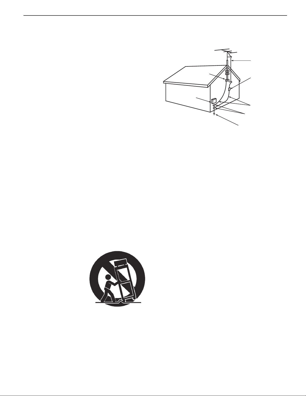
EXAMPLE OF ANTENNA GROUNDING
ANTENNA
LEAD IN WIRE
GROUND CLAMP
ELECTRIC
SERVICE
EQUIPMENT
NEC — NATIONAL ELECTRICAL CODE
ANTENNA
DISCHARGE UNIT
(NEC ARTICLE 810.20)
GROUNDING
CONDUCTORS
(NEC ARTICLE 810.21)
GROUND CLAMPS
POWER SERVICE GROUNDING
ELECTRODE SYSTEM
(NEC ART 250)
Outdoor Antenna Grounding
If an outside antenna or cable system is connected
to the TV, be sure the antenna or cable system is
grounded so as to provide some protection against
voltage surges and built-up static charges.
Replacement Parts
When replacement parts are required, be sure the
service technician has used replacement parts specified by the manufacturer or have the same characteristics as the original part. Unauthorized substitutions
may result in fire, electric shock or other hazards.
11) Only use attachments/accessories specified by the
manufacturer.
12) Use only with the cart,
stand, tripod, bracket,
or table specified
by the manufacturer,
or sold with the
apparatus. When
a cart is used, use
caution when moving
the cart/apparatus
combination to avoid
injury from tip-over.
13) Unplug this apparatus
during lightning storms or when unused for long
periods of time.
14) Refer all servicing to qualified service personnel.
Servicing is required when the apparatus has been
damaged in any way, such as power-supply cord or
plug is damaged, liquid has been spilled or objects
have fallen into the apparatus, the apparatus has
been exposed to rain or moisture, does not operate
normally, or has been dropped.
To avoid the risk of injury to the eyes and face, do not
look directly into the air vents while the television is
operating.
To avoid the risk of fire, do not use flammable solvents
(such as benzene or paint solvents) or flammable aerosols (such as polishes, cleaners, or insecticides) near
the television while it is operating or cooling.
For assistance call 1(800) 332-2119

6
1
Additional TV Features
FAV (Favorites)
The
FAV
key gives you quick access to favorite program
sources. Sources can be channels from the
or devices connected to the TV. You can store up to
nine favorites.
Sample Favorites menu. Switch to favorite channels or
inputs using number keys.
1. Press
2. Press the
3. Move the highlight to the number position you
Adding Favorites
4. Press
INPUT
and switch the TV to the input you
want to add. If adding a channel, switch to
the
ANT
input and tune to the channel.
FAV
key.
want to assign to the channel or input.
ENTER
.
ANT
input
Sleep Timer
The Sleep Timer turns the TV off after the length of time
you set. To set the TV to turn on at a certain time of
day, see the Setup > Timer menu.
Setting the Sleep Timer
1.
Press
SLEEP
.
2.
Press
SLEEP
additional times to increase the time in
30-minute increments up to the maximum of 120
minutes.
3.
Press
EXIT
or wait five seconds without pressing any
keys for the message to clear.
Viewing or Changing the Sleep Timer
1.
Press
SLEEP
to display the on-screen message.
2.
Press
SLEEP
additional times to change the time
before the TV powers off. To cancel the Sleep
Timer, press
played.
SLEEP
repeatedly until OFF is dis-
1. While watching TV, press the
2. In the Favorites menu, highlight the channel
or input you want to remove.
Removing
3. Press
1. While watching TV, press the
2. Press the number key for the channel or input
Tuning
CANCEL
you want.
.
FAV
FAV
key.
key.
For assistance call 1(800) 332-2119
1. Additional TV Features 7
Picture Shape and Display Formats
Format Definitions
Use the
Standard: The full-screen format used by HDTV
signals. Use this format to display anamorphic DVDs
with a 1.78:1 or 1.85:1 aspect ratio. Anamorphic DVDs
with a 2.35:1 aspect ratio are displayed correctly but
with top and bottom black bars. Squarish (4:3) images
are stretched evenly from side to side. Available for all
signals.
Expand: Enlarges the picture to fill the screen by
cropping the top and bottom; useful for reducing the
letter box top and bottom bars of non-anamorphic DVD
images.
FO RMAT
key to apply the formats described here.
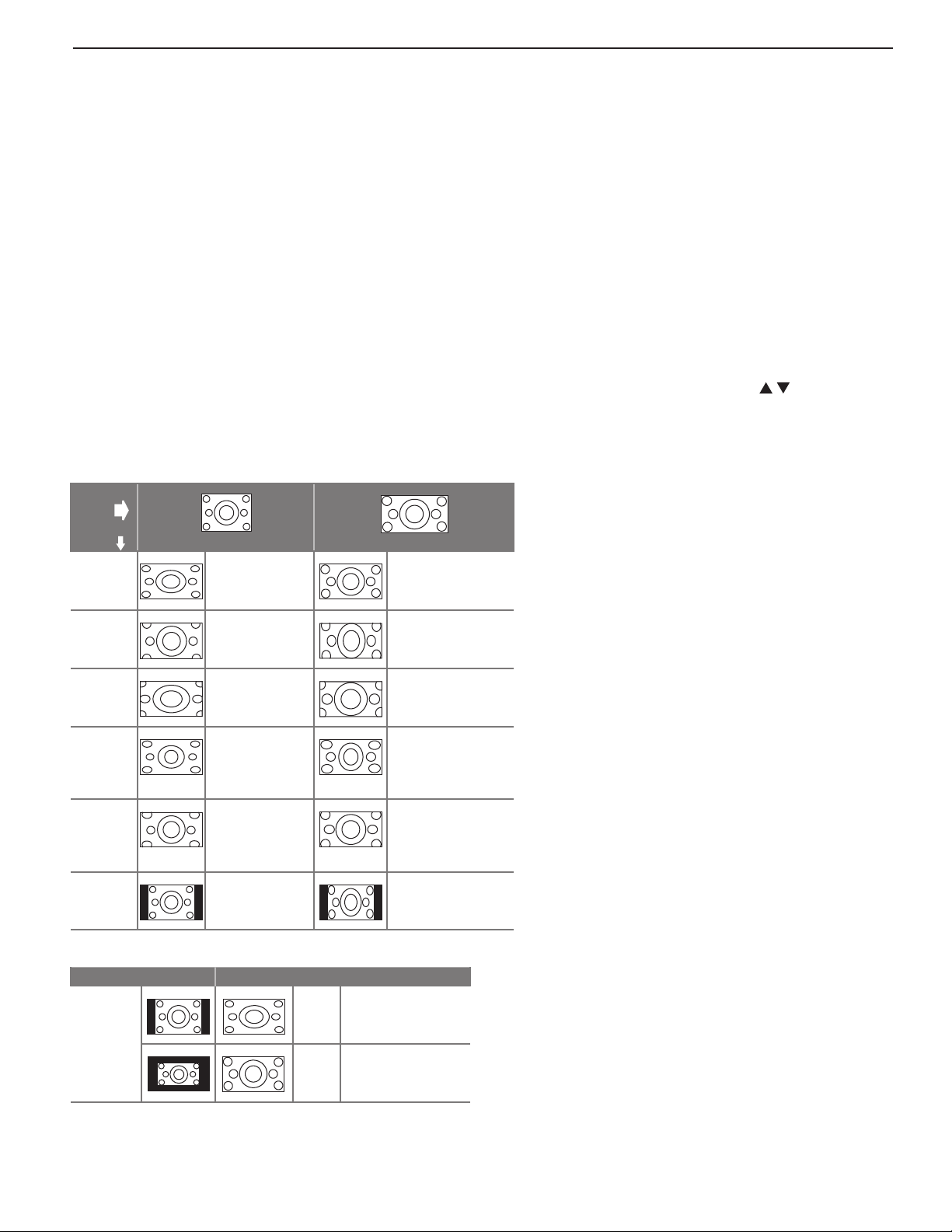
Effect of Mitsubishi Formats on Picture Types
Original
Signal
TV Display
Format
Standard
Expand
Non-anamorphic or SD 4:3 Anamorphic DVD
Distorted; Not
recommended.
Recommended
for letterbox.
See Note 1.
Recommended
Distor ted; not
recommended. See
No te 1.
Zoom: Enlarges the picture to fill the screen by cropping the sides, top, and bottom to eliminate black bars.
• 480i/480p and SD 4:3 signals: Eliminates top and
bottom bars on anamorphic DVDs with a 2.35:1
aspect ratio.
• 720p, 1080i, SD 16:9, and HD signals: Eliminates
bars added to squarish 4:3 images.
Stretch: Stretches a squarish 4:3 image across the
screen to display the entire image with less distortion
than the Standard format.
Stretch Plus: Similar to Stretch, but minimizes distortion on the sides by expanding the picture to crop off
portions of the top and bottom. Use
to adjust the
vertical position of the picture.
Narrow: Displays narrow 4:3 images in their original shape. Adds black side bars to fill the screen.
Wide Expand: Enlarges the picture, cropping the
image on both sides. Removes or reduces black
side bars added to narrow images converted to
16:9 signals for digital broadcast.
Note: All high-definition channels send widescreen (16:9) signals, but not all programming was
created for the widescreen format. The broadcaster may stretch the image or add side bars to
fill the widescreen area.
Zoom
Stretch
Stretch
Plus
Narrow
Distorted; Not
recommended.
See Note 1.
Recommended
for standard
broadcasts. See
No te 1.
Recommended
for standard
broadcasts. See
No te 1.
See Note 1. Distor ted; not
Recommended for
anamorphic 2.35:1
images. See Note 1.
Distor ted; not
recommended. See
No te 1.
Distor ted; not
recommended. See
No te 1.
recommended. See
No te 1.
Note 1: Available for 480i and 480p signals only.
Original Signal Display Formats
SD 16:9 or
HD Digital
720p,
1080i,
1080p
Signal
TV Display Formats. Press the
Wide
Expand
Zoom
FO RMAT
Recommended to
remove side bars.
Recommended to
remove bars from the
top, bottom, and sides.
key repeatedly to see
different displays for the current program. Press the
see the name of the format in use.
INFO
DVD Image Definitions
Image information may be stated on the DVD
case. Some DVDs support both formats
described below.
Anamorphic (or Enhanced for WideScreen TV)
Indicates DVDs recorded to show widescreen
images properly on 16:9 TV sets using the TV’s
Standard format mode (recommended).
Non-Anamorphic (or 4:3, 1.33:1, Letter Box, or
Full Screen)
Indicates DVDs recorded for viewing on squarish TV screens. They may be full screen (4:3 or
1.33:1) which crops movies to fit the narrow TV, or
letter box, which adds black top and bottom bars.
key to
For assistance call 1(800) 332-2119
8 1. Additional TV Features
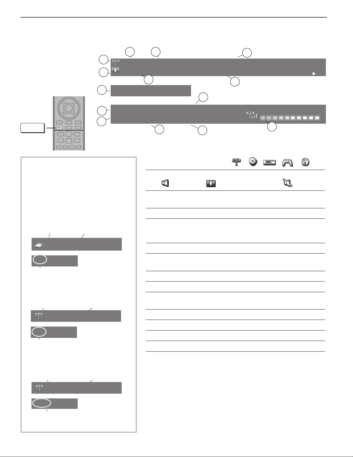
Status Display
Press the
INFO
key to see
the on-screen status
display. The most
1
2
common displays are
shown here.
8
Sleep 30 min
Tuesday 9:10 PM
9
1080i Standard
10
INFO
About Channel Numbers
Channel Numbers for Over-the-Air
Reception or Reception by Direct
Cable
Note: All signals are automatically
converted to 1080p for display.
Standard-Definition Analog Channels
Cable Reception
Cable 3
Channel 3
3
4
6
402-101 K ABC Monday Night Football
TV-PG DLSV
5
11
1.
Current Input. Examples:
2. Audio Indicator. Key:
3. Channel number (antenna source only)
Digital channel includes major and sub-channel numbers.
4. Digital channel name (if broadcast); antenna source only.
5.
V-Chip rating
• Digital signal: Antenna source only
• Analog signal:
6. Program name (if broadcast); digital antenna source only
St. Louis vs. Tampa Bay, played in Tampa for
7
Sample information from the
13
on-screen status display
English
Surround
12
Antenna
DVD
TV speakers External sound system Mute
Antenna or
VIDEO
14
DVR
Game
composite jack
Sat . Rcvr.
480i Stretch
Receiving Standard-Definition
Analog Signal (48 0i)
Standard-Definition Digital Channels
Over-the-Air
Antenna
Reception
Main Channel 7
Sub-Channel 1
Ant 7-1 KABC-SD
480i Stretch
Receiving Standard-Definition
Digital Signal (SD)
High-Definition Digital Channels
Over-the-Air
Antenna
Reception
Main Channel 7
Sub-Channel 1
Ant 7-1 KABC-HD
1080i Standard
Receiving High-Definition
Digital Signal (HD)
7. Program description (if broadcast); digital source,
Press the
INFO
key additional times to see more of the description.
antenna only.
8. Sleep Timer remaining time
9. Day and time
10. Signal type being received. See “Signal Definitions” on this
page.
11. Screen format in use
12. Program audio indicator (antenna source only)
13. Available language (digital source, antenna only)
14. Signal-strength indicator (digital source, antenna only)
Signal Definitions
480i: Standard-definition, older type interlaced signals from the
composite
VIDEO
, component
Y Pb Pr
, or
HDMI
jacks.
480p: Standard-definition progressive-scan signals on the
component
Y Pb Pr,
or
HDMI
jacks.
720p and 1080i: High-definition signals received through the
component
Y Pb Pr,
or
HDMI
jacks. These signals are always 16:9
(widescreen), but may contain embedded 4:3 images with sidebars.
1080p: High-definition signals from a PC, Blu-ray player, or some
satellite and set-top boxes; HDMI inputs only.
ANT
ANT,
ANT
,
,
For assistance call 1(800) 332-2119
1. Additional TV Features 9
21
3 4
3D
GLASSES
EMITTER
ANT
HDMI
L
R
DIGITAL
AUDIO
OUTPUT
AUDIO/SURROUND
-OUTPUT-
R
L
LANUSB-P
CENTER
INPUT
SUB WOOFER
OUTPUT
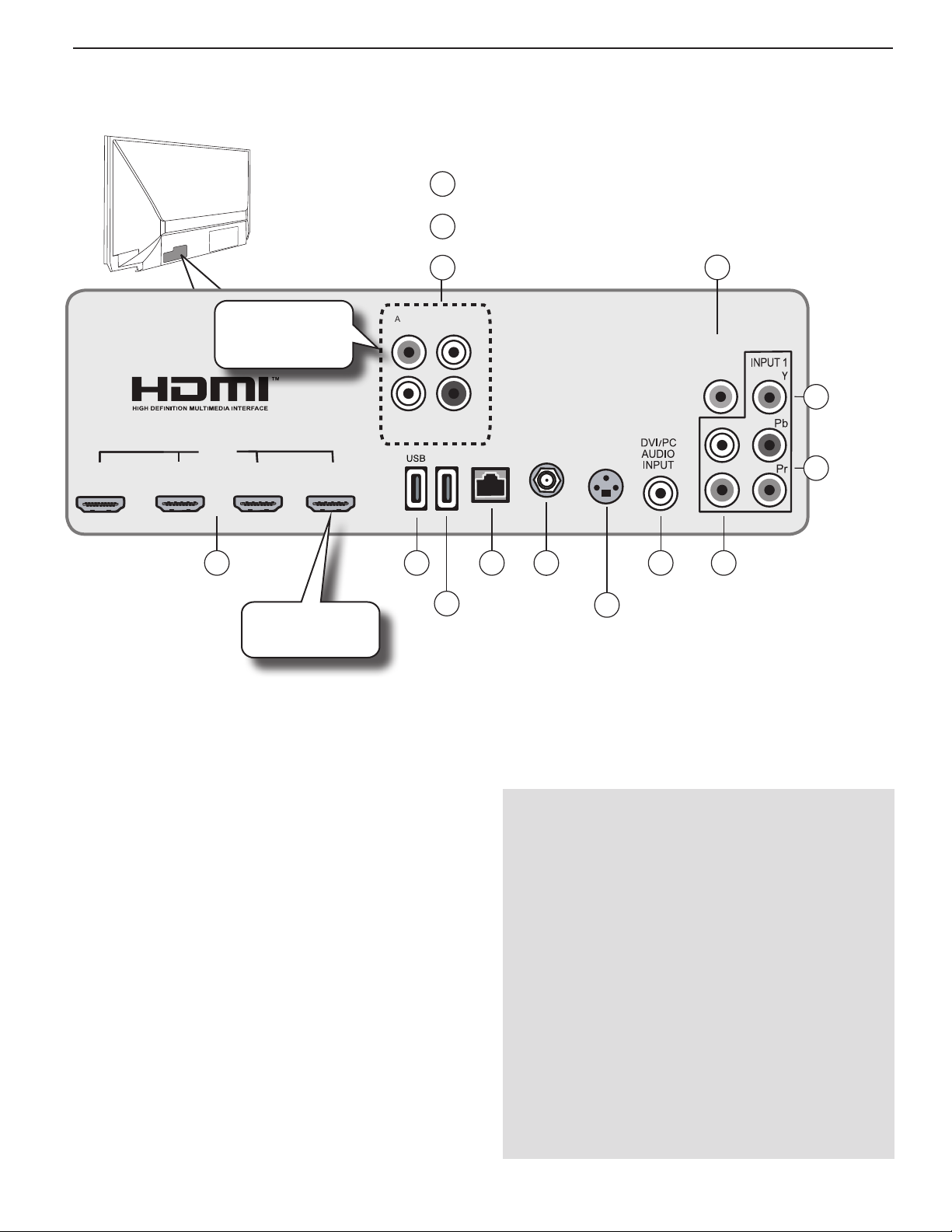
More On TV Inputs and Outputs
AUDIO/SURROUND
12
Additional jacks
offered on the
842 series.
OUTPUT, L/R
CENTER INPUT
13
SUBWOOFER OUTPUT
14
DIGITA L
AUDIO
OUTPUT
11
10
Y
Composite
video input
9
Y Pb Pr
Component
video input
1 2
HDMI USB
3
HDMI-4 offered
on the 842 series.
USB-P
(842 Series)
The Basic Owner’s Guide supplied with your TV contains connection diagrams showing how to use most of
these jacks.
1. HDMI® Inputs
(High-Definition
Multimedia Interface)
The HDMI inputs support uncompressed standard and
high-definition digital video formats, bitstream Dolby
Digital 5.1, and PCM digital stereo audio. These inputs
are HDCP (High-Bandwidth Digital Copy Protection)
compliant.
Mitsubishi recommends you use high-speed HDMI
cables to connect newer source devices incorporating
HDMI technology. High-speed cables bring you the full
benefits of Deep Color.
These HDMI inputs can also accept digital DVI video
signals. To connect a device’s DVI output to the TV’s
HDMI input, use an HDMI-to-DVI adapter or cable plus an
analog audio cable. Connect the audio cable to the
PC AUDIO INPUT
jack on the TV to receive audio from
your DVI device.
Use the HDMI inputs to connect to CEA-861 HDMI compliant devices such as a high-definition receiver or DVD
DVI/
4 87
LAN
5
ANT
6
3D
DVI/PC
AUDIO
INPUT
L/R
Analog stereo
audio inputs
GLASSES
EMITTER
player. These inputs support 480i, 480p, 720p, 1080i,
and 1080p video formats.
The TV’s HDMI inputs are compatible with many DVI-D
and HDMI computer video signals.
HDMI Cable Categories
HDMI cables are available as Standard and High-Speed
types.
• High-Speed HDMI Cables. Blu-ray players, newer
DVD players, video games, 3D content, and set-top
boxes require High-Speed HDMI cables, suitable
for clock frequencies up to 340 MHz or data rates
of up to 10.2 gigabits per second. Use high-speed
cables for 1080p HD signals carrying extended color
encodings (i.e., 30 or more bits, also called Deep
Color). High-Speed HDMI cables are also suitable for
standard HDTV signals.
• Standard HDMI Cables. Standard HDMI cables
may be unmarked. They are suitable for standard
HDTV 720p, 1080i, and 1080p signals with 8-bit color
depth. Use Standard HDMI cables for clock frequencies up to 74.25 MHz or data rates of up to 2.23
gigabits per second.
For assistance call 1(800) 332-2119

10 1. Additional TV Features
More On TV Inputs and Outputs, continued
2. USB
• Use for a wireless network adapter to receive
StreamTV Internet content.
• Use this port when updating the TV software using
a USB memory device.
• The USB port can also serve as a standard USB
5-volt, 500-milliamp power output to power an
accessory device.
3. USB-P (Power Only)
842 Series. Standard USB 5-volt, 500-milliamp power
output you can use to supply power to an accessory
device. See page 14.
4. LAN
Use the
to the TV.
LAN
Ethernet jack for streaming Internet video
5. ANT (Antenna)
Connect your main antenna or direct cable service
(without a cable box) to
digital and analog over-the-air channels from a VHF/
UHF antenna or non-scrambled digital/analog cable
source.
ANT
. The
ANT
input can receive
6. 3D GLASSES EMITTER
Use this jack for the special synchronization emitter supplied with some 3D glasses. The emitter sends out an
infrared signal that synchronizes your 3D glasses with the
screen display.
7. DVI/PC AUDIO INPUT
Connect a DVI device to one of the TV’s HDMI inputs
and use this jack to send analog audio to the TV.
8. L/R (INPUT 1 audio)
Analog stereo inputs for use in conjunction with adjacent composite or component video jacks.
10. Y (Composite Video)
Analog standard-definition video inputs. Use the adjacent R and L inputs if you wish to send audio to the TV
speakers.
11. DIGITAL AUDIO OUTPUT
This output sends Dolby Digital or PCM digital audio
to your digital A/V surround sound receiver. Incoming analog audio is converted by the TV to PCM digital
audio. If you have a digital A/V receiver, this is the only
audio connection needed between the TV and your A/V
re c e i ver.
12. AUDIO/SURROUND OUTPUT, L/R
842 Series. Provides analog audio output of the
current program. Use to:
• Send audio to an analog A/V surround sound
receiver or stereo system.
• Send a rear surround sound channel to an external
amplifier or self-powered speakers. See page 15.
• Send audio to headphones. Set Sound > Global >
Analog Audio Out to Variable.
Digital audio from digital channels and HDMI devices is
converted to analog audio by the TV for output on these
jacks.
13. CENTER INPUT
842 Series. Connect your A/V receiver’s center
channel output to this input to have the TV speakers complement your external sound system with
center-channel sound. Set Sound > Global > Center
Channel to On to enable this input. See “Using the TV
Speakers as a Center Channel,” page 16.
14. SUBWOOFER OUTPUT
842 Series. Connect a powered subwoofer to this
input to complement effects from the TV’s speakers.
Set Sound > Global > Subwoofer to On to enable this
output (see “Adding a Subwoofer,” page 14).
9. Y Pb Pr (Component Video)
Analog video inputs able to accept high-definition video
from a high-definition source device. Use the adjacent R and L inputs if you wish to send audio to the TV
speakers.
For assistance call 1(800) 332-2119
1. Additional TV Features 11
AUDIO/SURROUND
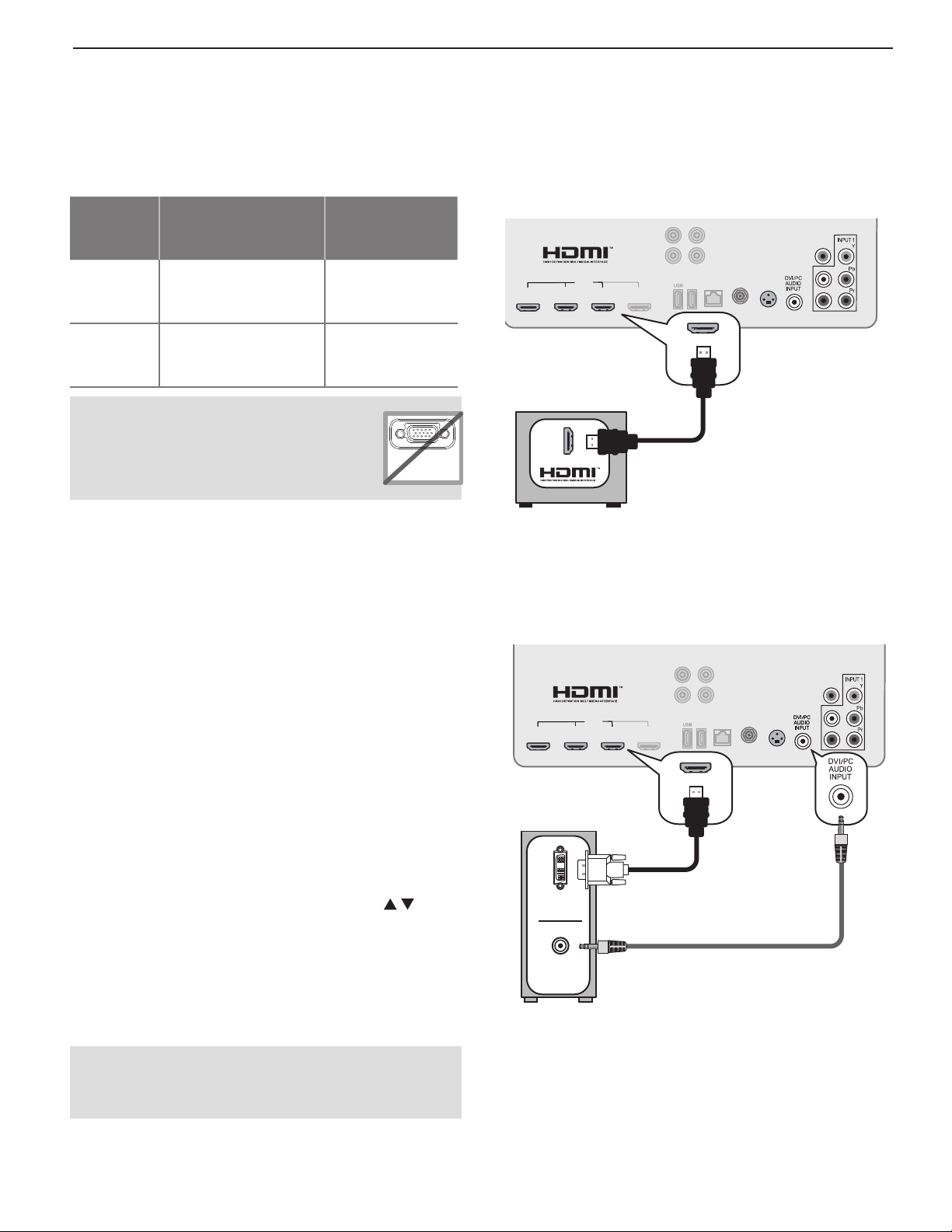
Using the TV with a Personal Computer
H
Connecting a Computer to the TV
Use one of the connection methods listed below based
on your computer’s output.
Computer
Graphics
Output
Digital DVI DVI-to-HDMI cable or
HDMI HDMI-to-HDMI cable No additional
This TV accepts digital computer
graphics signals only. This TV is not
compatible with VGA (analog) computer
signals.
Computer Graphics
Connection
an HDMI cable with a
DVI-to-HDMI adapter
IMPORTANT
Audio
Connection
Audio cable with
mini-plugs
audio connection
is required.
VGA
PC MONITOR OUT
DMI Connection
Mitsubishi recommends using high-speed HDMI cables
to connect newer devices incorporating HDMI technology.
-OUTPUT-
L
R
CENTER
SUB WOOFER
INPUT
OUTPUT
ANT
1
3 4
HDMI
2
USB-P
LAN
GLASSES
EMITTER
TV jack panel
Computer with HDMI output
DIGITAL
AUDIO
OUTPUT
3D
L
R
1.
Connect the computer’s digital video output to
one of the TV’s HDMI jacks. See the connection
diagrams on this page for the method suited to your
equipment.
2.
Connect the computer’s audio output using one of
these options:
• FordigitalDVIvideosignals,connectthe
analog audio output to the TV’s
INPUT
jack.
DVI/PC AUDIO
• ForHDMIsignals,noadditionalaudioconnection is required.
Note: If you are unable to hear audio from the
computer, there may be an incompatibility in
the computer’s hardware, software, or internal
settings. Consult a trained computer technician
for advice.
3.
Power on the TV and computer. The TV will detect
the connection and display the New Device Found
screen.
4.
In the New Device Found screen, press to
highlight PC in the list of device types. It is important to use the name PC so that the TV processes
the PC signal correctly.
5.
Highlight EXIT and press
ENTER
to close the New
Device Found screen.
An HDMI-to-HDMI connection carries all video and
audio on a single cable.
DVI Video Connection
AUDIO/SURROUND
-OUTPUT-
L
R
CENTER
1
3 4
HDMI
2
INPUT
TV jack panel
DVI OUT
AUDIO
OUT
DVI-to-HDMI cable
Analog audio cable
with mini-plugs
Computer with DVI and
analog audio outputs
SUB WOOFER
OUTPUT
USB-P
ANT
LAN
GLASSES
EMITTER
DIGITAL
AUDIO
OUTPUT
3D
L
R
Note: If your computer provides digital audio
output you can connect it directly to a digital
A/V receiver and bypass the TV.
A DVI connection from a personal computer requires a
separate audio connection.
For assistance call 1(800) 332-2119
12 1. Additional TV Features
DIGITAL
AUDIO
OUTPUT
AUDIO/SURROUND
-OUTPUT-
R
L
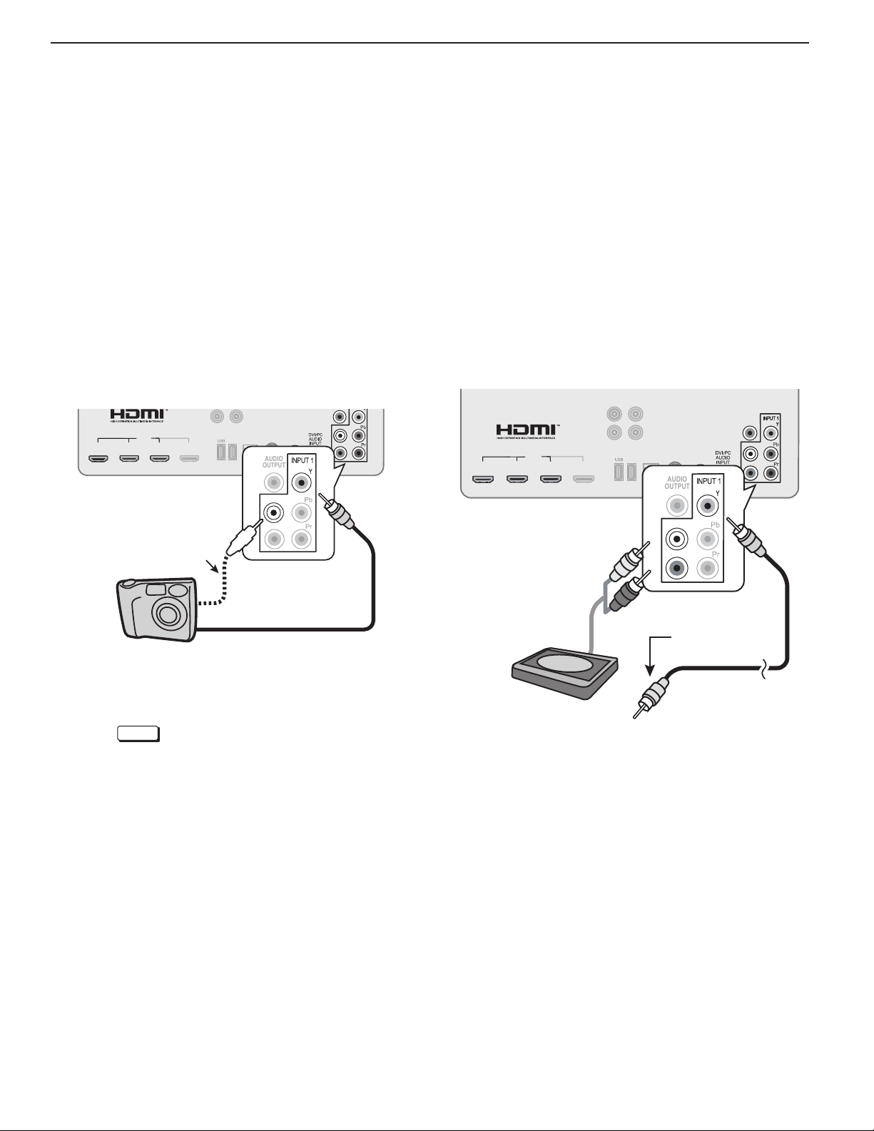
Specialized TV Connections
Photos and Motion Video as Composite
Video
Connect the camera to the TV using a composite video
cable and control the slide show or movie through the
camera. The display resolution will be standard-definition (480i).
1.
Refer to the owner’s manual supplied with the
camera for instructions needed for this setup.
2.
Set the camera’s output signal type to NTSC and
put the camera into playback mode.
3.
With the camera still turned on, connect your digital
camera’s composite video cable (usually yellow) to
the TV’s Y composite video jack. To hear audio,
connect the camera’s audio output cable to the
audio L jack.
CENTER
SUB WOOFER
INPUT
HDMI
2
1
3 4
TV jack panel
Optional
Audio Cable
USB-P
OUTPUT
ANT
DIGITAL
AUDIO
OUTPUT
L
R
GLASSES
EMITTER
LAN
L
L
3D
R
R
Using the TV with an Audio-Only Device
To use the TV speakers to listen to an audio device
such as an MP3 or CD player with analog output, follow
these steps.
1.
Insert an unused RCA-style connector into the
Y
composite video jack. The presence of this con-
nector activates the TV’s auto-detection.
2.
When the TV detects the video connector, it will
display the New Device Found screen. Name the
new input CD/Audio or MP3 Player.
3.
Connect left (white) and right (red) audio cables
from
AUDIO OUT
4.
Keep the connector in the Y jack while using the
audio-only device.
HDMI
2
1
TV jack panel
on the device to
3 4
AUDIO/SURROUND
-OUTPUT-
R
CENTER
SUB WOOFER
INPUT
USB-P
OUTPUT
L and R
L
ANT
DIGITAL
AUDIO
OUTPUT
L
R
GLASSES
EMITTER
LAN
3D
on the TV.
DIGITAL
AUDIO
OUTPUT
L
L
R
R
Camera connection using a composite video cable
4.
When the New Device Found screen displays,
assign the name Camcorder.
5.
Press
EXIT
to close the New Device Found
screen.
6.
If viewing photos, control the slideshow from the
camera. Advance through the images manually or
check if the camera can advance automatically.
Audio-only
device
Audio
cables
2.
Unused
RCA-style plug
(plug in first)
1.
For assistance call 1(800) 332-2119
1. Additional TV Features 13
Computer Video Adjustments
1.
Power on the computer.
2.
Select PC from the Input Selection menu. To do
this, press
move the highlight to the PC icon, and press
3.
Working from the computer, change the resolution
of the computer image. View the computer image
on the TV and maximize the computer
resolution while maintaining a suitable
aspect ratio for the image.
4.
Press
picture shape best suited to the
image. See the chart on this page
showing how different computer resolutions can be displayed on the TV.
5.
Perform TV video adjustments. Press
VIDEO
adjustment options.
INPUT
to open the Input Selection menu,
FO RMAT
repeatedly to access video-
repeatedly to find the
Tip
Set the computer’s screen saver to display a pattern
after several minutes of inactivity. This acts as a
reminder that the TV is powered on.
ENTER.
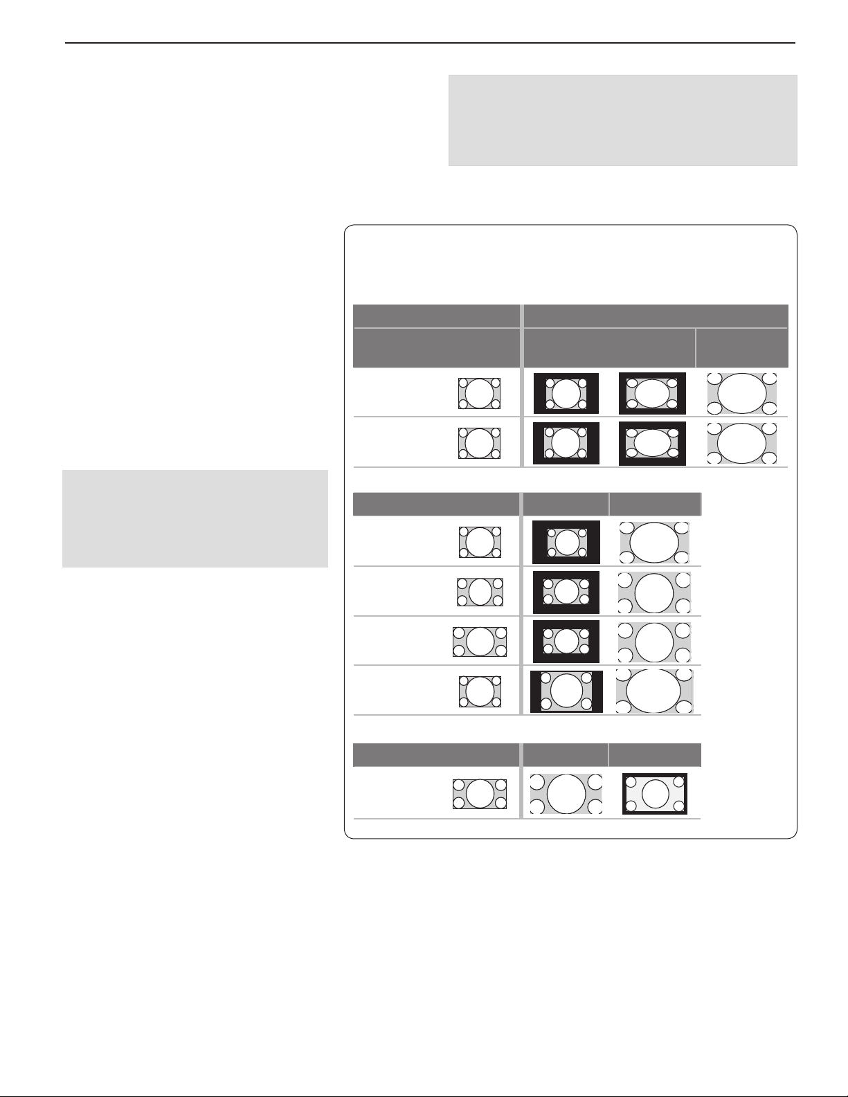
Computer Display Formats
Press
FO RMAT
your computer’s video signal.
Computer Signal
Original Format
VGA
640 X 480
SVGA
800 X 600
repeatedly to cycle through the TV displays available for
4 X 3
Standard
As Displayed on TV Screen
16 X 9
Standard
Zoom
Distortion in Computer Images
Computer images may show distortion
when viewed on the TV, e.g., lines that
should be straight may appear slightly
curved.
Image Resolution
Your Mitsubishi TV can display the resolutions shown in the chart from standard
VGA (640 x 480) through 1920 x 1080
signals at a refresh rate of 60 Hz.
In most cases, the computer will select the
best resolution match to display on the TV.
You can override this setting if you wish.
Refer to your computer operating system’s
instructions for information on changing
the screen resolution.
You may need to restart the computer for
changes to take effect.
Original Format Standard Zoom
XGA
1024 X 768
PC 720p
1280 X 720
WXGA
1360 X 768
SXGA
1280 X 1024
Original Format Standard Reduce
PC 1080p
1920 X 1080
For assistance call 1(800) 332-2119
14 1. Additional TV Features
3D
GLASSES
EMITTER
ANT
DIGITAL
AUDIO
OUTPUT
AUDIO/SURROUND
-OUTPUT-
R
L
LAN
CENTER
INPUT
SUB WOOFER
OUTPUT
USB-P
1
2
3 4
HDMI
L
R
SUB WOOFER
OUTPUT
USB-P
USB/USB mini-plug
power cable
RCA audio cable
TV
Polk Audio PSW i8m
powered wireless
subwoofer
Supplemental Audio Connections (842 series)
Add a subwoofer to complement the TV’s speaker array
or use the TV’s speakers as a center channel for your
external sound system.
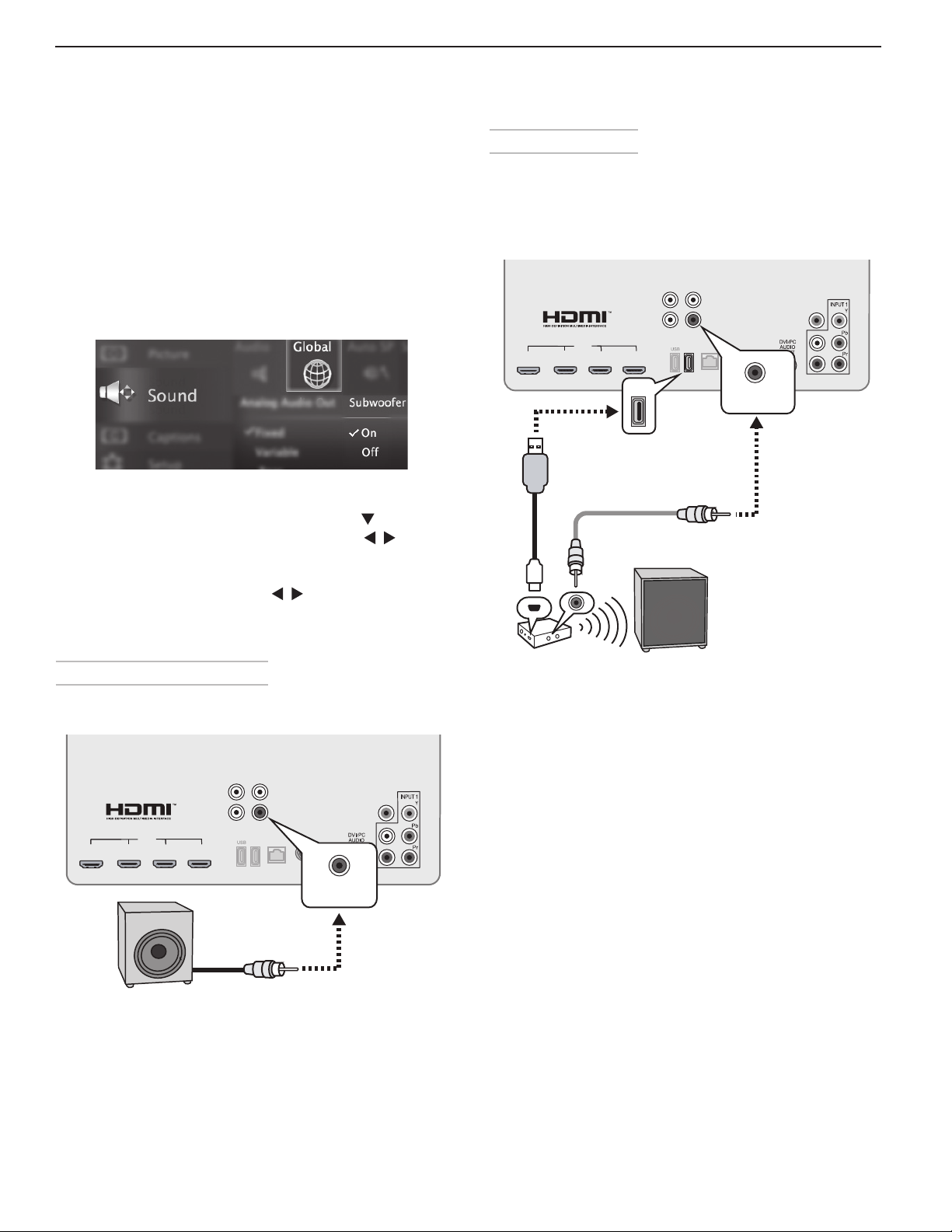
Adding a Subwoofer
Add a subwoofer to complement the TV speakers with
a fuller bass sound.
• After connecting a subwoofer, you must enable the
TV’s subwoofer output in the TV’s Sound menu. Go
to
Sound > Global > Subwoofer and set it to On.
• To control subwoofer volume
- Press the
the subwoofer volume slider. Press to
change the volume.
- Open the Sound > Audio menu. Highlight
Subwoofer and press to adjust. Press
MENU
AUDIO
key and then press to find
to return to the Sound > Audio menu.
Wireless Subwoofer
Mitsubishi recommends Polk Audio Wireless Subwoofer
model PSW i8m. The transmitter module can be
conveniently powered from the TV’s USB power port.
Connect an audio cable to the transmitter to supply
audio from the TV’s
SUBWOOFER OUTPUT
.
Subwoofer with Audio Cable
Connect the subwoofer directly to the TV’s
OUTPUT
Subwoofer with audio connection to TV.
1
.
AUDIO/SURROUND
-OUTPUT-
L
R
CENTER
SUB WOOFER
INPUT
OUTPUT
LAN
USB-P
2
HDMI
3 4
3D
ANT
GLASSES
EMITTER
SUB WOOFER
OUTPUT
SUBWOOFER
DIGITAL
AUDIO
OUTPUT
L
R
Setup to send audio signals wirelessly to the subwoofer.
For assistance call 1(800) 332-2119

1. Additional TV Features 15
Supplemental Audio Connections (842 series), continued
External Rear Speakers
You may wish to supplement surround sound from the
TV with external rear speakers. External speakers can
fill in rear sound if your room lacks a rear wall suitable
for sound reflections. Mitsubishi recommends Polk
Audio’s F/X Wireless Surround system.
1
3 4
HDMI
2
AUDIO/SURROUND
-OUTPUT-
R
CENTER
SUB WOOFER
INPUT
USB-P
OUTPUT
L
AUDIO/SURROUND
ANT
GLASSES
OUTPUT
LAN
EMITTER
DIGITAL
AUDIO
OUTPUT
3D
L
LR
R
Transmitter
TV
Polk Audio F/X
Wireless Surround
speaker unit
Sample layout using an external speaker unit in a room
without a back wall suitable for rear sound reflections
1.
Position the external speakers as needed for rear
sound.
2.
Connect analog audio output from the TV to the
Polk Audio F/X Wireless Surround transmitter.
3.
Power on the TV, speakers, and transmitter.
4.
Set Sound > Global > Analog Audio Out to Rear.
To transmitter left and
Transmitter
right audio inputs
Connecting the transmitter to the TV
To TV audio
outputs
5.
Adjust the sound output. Go to the Sound >
SoundPro > CUSTOM menu.
a. Adjust beam angles for the left, right, and
center beams.
b. Adjust volume levels for all audio beams,
including the left and right surround beams.
6.
Play sample audio to check the sound. Repeat any
of the adjustments as needed.
Sound Projector adjustments when using external rear
speakers.
For assistance call 1(800) 332-2119
16 1. Additional TV Features
Supplemental Audio Connections (842 series), continued
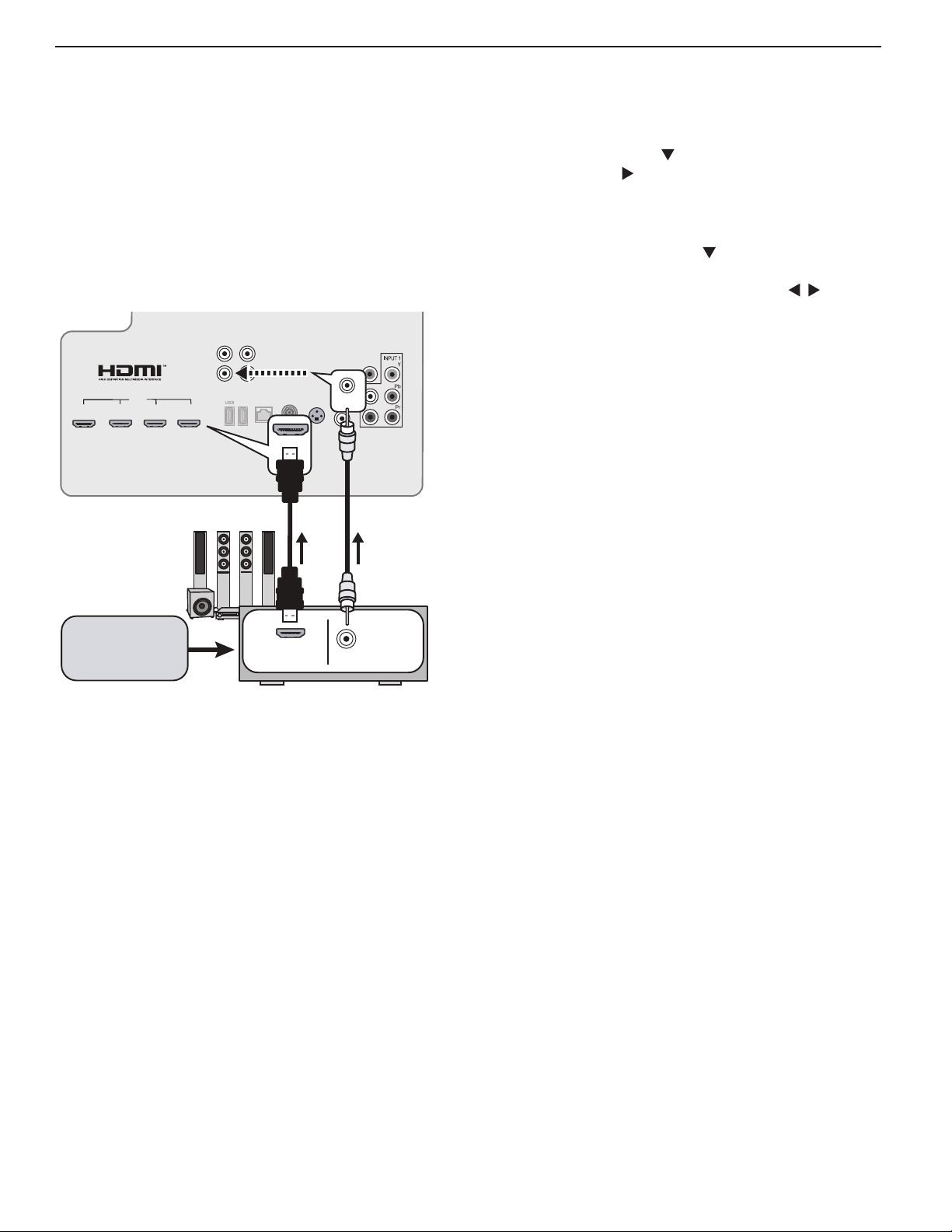
3.
Using the TV Speakers as a Center Channel
If using an external surround sound system, you can
use the TV’s speakers to provide center channel sound.
Your A/V receiver must have a center channel pre out
that can supply a pre-amplified center-channel signal to
th e T V.
1.
Connect your A/V receiver’s HDMI output and
center channel pre out to the TV as shown.
AUDIO/SURROUND
-OUTPUT-
L
R
CENTER
SUB WOOFER
INPUT
OUTPUT
ANT
1
3 4
HDMI
2
USB-P
LAN
GLASSES
EMITTER
DIGITAL
AUDIO
OUTPUT
L
3D
CENTER
INPUT
R
Enable the TV’s center channel mode. Press the
AUDIO
key and press to display the TV Speakers
option. Press to select Center.
4.
Compare the center channel volume from TV’s
speakers to the rest of the sound system. If the
center channel volume needs adjustment,
a. Press
Level
volume slider
b.
Adjust TV speaker volume using
c. Compare the center channel volume to the rest
of the sound system. Repeat this adjustment if
needed.
AUDIO and press to display the
.
the
Center
keys.
HDMI cable
RCA/RCA
audio cable
A/V receiver
with HDMI
output
CENTER
Surround sound
source device
2.
Turn on the A/V receiver’s center channel pre out if
HDMI OUT
CHANNEL
PRE OUT
needed. See the A/V receiver’s instruction manual.
For assistance call 1(800) 332-2119
1. Additional TV Features 17
DIGITAL
AUDIO
OUTPUT
AUDIO/SURROUND
-OUTPUT-
R
L
StreamTV™ Internet
2.
About StreamTV
Internet services let you access many popular on-line
applications providing both free and paid content.
This section describes using VUDU Movies and VUDU
Apps. For additional Stream TV features, see the supplemental Owner’s Guide at www.mitsubishi-tv.com.
Required for StreamTV Internet media:
• Broadband Internet service (at least 2 Mbps for SD,
4 Mbps for HD, and 8 Mbps for 1080p HDX)
• Category-5 Ethernet cable or a wireless router
transmitting to an
less adapter.
• Computer access to the websites of content providers when initial account activation is required for
service.
• A credit card to cover the cost of paid content.
AzureWave AW-NU231 USB wire-
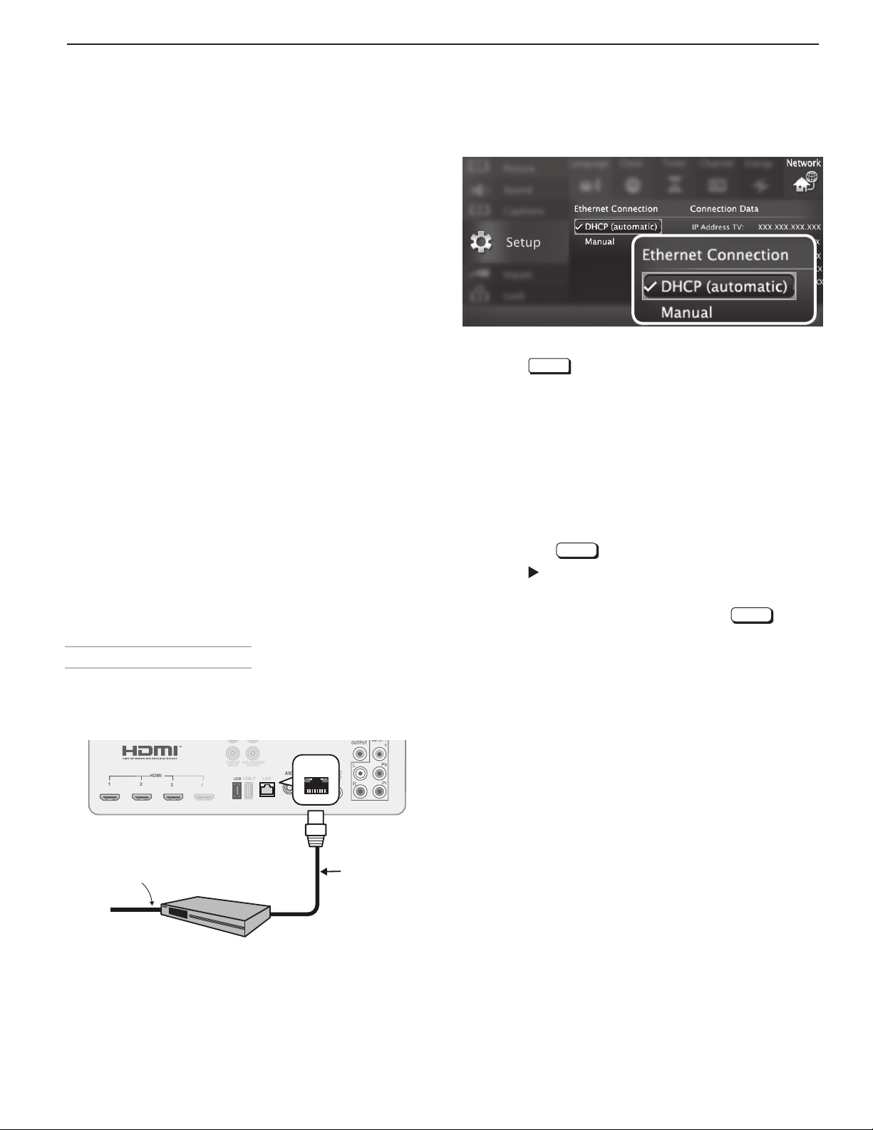
Open the Setup > Network menu to review settings.
Setup > Network, DHCP connection
3.
4.
Press
Press the
EXIT
to clear the menu.
INTERNET
key on the remote control to
begin using this feature.
Remote PC
• You can display the PC screen on the TV via a
home LAN network to use e-mail, social network
services (SNS), and other online services on the TV.
Home Network Setup
Before using StreamTV Internet media, you must
connect the TV to the Internet using either an Ethernet
cable or a wireless connection as described here.
Note: Make sure the TV is on any input other
Bluetooth®. Press the
INPUT
key to change.
Wired Ethernet Connection
DHCP (automatic)
1.
Connect the TV to your network router with a Category-5 Ethernet cable
HDMI
2
1
3 4
TV Panel
(not supplied).
CENTER
SUB WOOFER
INPUT
OUTPUT
LAN
USB-P
LAN
LAN
3D
ANT
GLASSES
EMITTER
than
L
R
Manual
Note: Manual setup is available only for a wired con-
nection.
1.
Connect the TV to your network router with a Category-5 Ethernet cable
2.
In the Setup > Network menu, highlight Manual
and press
3.
Press to move to the Connection Data area.
4.
Input the connection data.
5.
After entering connection data, press
ENTER
.
(not supplied).
ENTER
to
connect.
6.
Change any of the following if needed:
• Default Gateway
• DNS
• Subnet Mask
Incoming
internet
cable
Router or modem
providing high-speed
internet service
Ethernet
cable
For assistance call 1(800) 332-2119
18 1. Additional TV Features
3D
GLASSES
EMITTER
ANT
DIGITAL
AUDIO
OUTPUT
AUDIO/SURROUND
-OUTPUT-
R
L
LAN
CENTER
INPUT
SUB WOOFER
OUTPUT
USB-P
1
2
3 4
HDMI
L
R
Wireless
adapter
Incoming
internet cable
IEEE 802.11n-compliant
wireless
network router providing
high-speed internet service
StreamTV™ Internet, continued
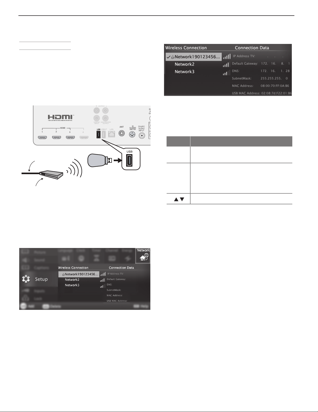
Wireless Connection
The TV requires an AzureWave AW-NU231 USB wireless
adapter to communicate with your IEEE 802.11n-compliant wireless network router. The adapter is available from
your Mitsubishi dealer or go to www.mitsubishi-tv.com
and follow the Accessories link.
1.
Disconnect the Ethernet cable if present.
2.
Connect the wireless adapter to the TV’s USB port.
Setup > Network menu after connecting. The active
network is checked and connection data displays.
5.
If connecting to a secure network, enter the
network key or password when prompted. Special
remote control keys you may need:
Key Use for
1
Digit 1 and special characters
! @ # $ % ^ * _ - + = . SPACE ?
Connect the USB adapter to the USB port on the back
of the TV. Use the left USB port.
3.
Open the Setup > Network menu. After a few
moments, detected networks will appear listed on
the screen in order of signal strength.
Setup > Network menu, wireless connection
4.
Highlight the desired network and press
connect. A check will appear next to the connected
network. Press
CH/PAGE
to see more networks if the
ENTER
to
list fills more than one screen.
CANCEL
• Clears the password box of an old
entry from a prior session.
• Deletes one character during password entry.
Toggle between upper and lower case
ENTER
to connect.
6.
Press
Using StreamTV Internet Media
1.
After establishing the Internet connectivity as
described in “Home Network Setup,” page 17,
switch the TV to any input other than Bluetooth®.
2.
Press the
3.
Press
INTERNET
ENTER
key to display services.
to launch an application.
Troubleshooting
If You Are Unable to Connect to the Internet
• Check all power and data connections.
• If you can reach the Internet with a computer or
other device on the same Internet service used by
the TV, consult the router or modem owner’s guide
for reset instructions.
• If you cannot reach the Internet, contact your
service provider. You may be asked for network
information such as the TV’s IP address. Go to the
Setup > Network menu to see connection data.
For Further Assistance
If you are having trouble connecting your TV or accessing the Internet applications, contact Mitsubishi Customer Care at 1 (800) 332-2119.
For assistance call 1(800) 332-2119
1. Additional TV Features 19
3D
GLASSES
EMITTER
ANT
DIGITAL
AUDIO
OUTPUT
AUDIO/SURROUND
-OUTPUT-
R
L
CENTER
INPUT
SUB WOOFER
OUTPUT
USB-P
1
2
3 4
HDMI
L
R
LAN
LAN
PC
Mouse
Keyboard
USB hub
Router
3D
GLASSES
EMITTER
ANT
DIGITAL
AUDIO
OUTPUT
AUDIO/SURROUND
-OUTPUT-
R
L
LAN
CENTER
INPUT
SUB WOOFER
OUTPUT
USB-P
1
2
3 4
HDMI
L
R
Router
Mouse
Keyboard
USB hub
Wireless
adapter
PC
StreamTV™ Internet, continued
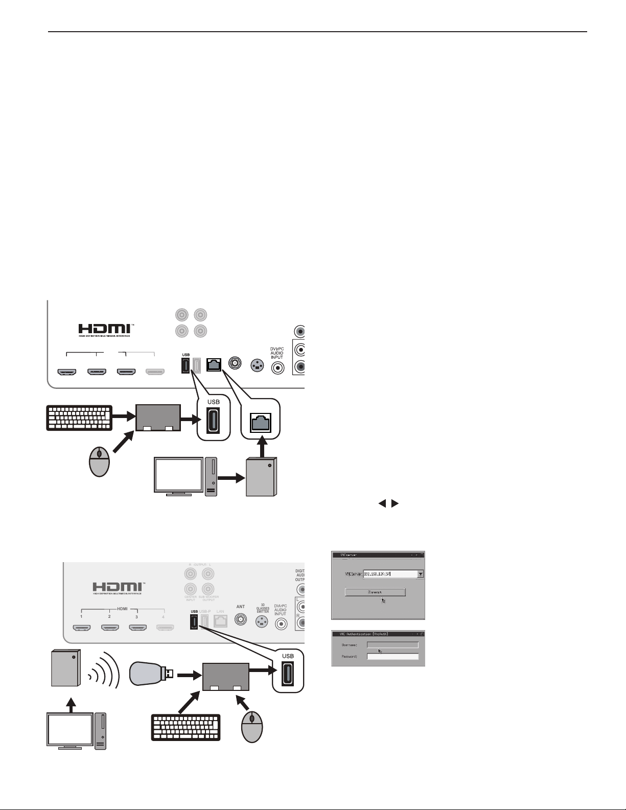
Remote PC (VNC)
This function allows you to display the PC screen on the
TV via a home LAN network.
Even when the PC is installed away from the TV, the TV
works as the VNCviewer and you can view and operate
the desktop screen of the PC using a keyboard or
mouse connected to the USB terminal of the TV.
This function is for viewing still image content of the
Web browser, e-mail, or other online services. Therefore, moving pictures cannot be played back smoothly
with this function.
Initial Setup
Wired connection with the VNC PC (server) via the
router
Wireless connection with the VNC PC (server) via the
router
Getting started with Remote PC (VNC)
1.
After establishing the Internet connectivity as
described in “Home Network Setup,” page 17,
switch the TV to any input other than Bluetooth®.
2.
Download the VNCServer software from the URL
below and install it on your PC.
MetaVNC (http://sourceforge.net/projects/metavnc/)
RealVNC (http://www.realvnc.com/)
The supported software versions are
metavnc-win32 0.6.6 and VNC free edition 4.1.
VNC provides access to the PC when the
VNCServer software available on the Internet is
installed on the PC.
The TV has only one USB port even though multiple
devices such as USB wireless dongle, USB keyboard,
and mouse are necessary. In order to use these additional devices, connect a USB hub to the USB port on
th e T V.
Note: The product operation is not guaranteed under
the following unusual conditions:
a. When USB hubs are connected serially.
b. When multiple keyboards and mice are con-
nected to the USB hub.
c. When multiple USB wireless dongles are con-
nected to the USB hub.
The USB port on the TV may not work when you
connect too many devices.
4.
Press the
selecting VUDU Apps, VUDU Movies, or Remote
PC.
5.
Press to select Remote PC and press the
ENTER key.
6.
Choose the IP address and type the password in
the log-in menu of the VNCviewer.
INTERNET
key to display the menu for
Example of the VNC log in menu
Example of the VNC password
menu
For assistance call 1(800) 332-2119
 Loading...