

Page 1
MT-24A
2 CE 5 9 3 A
FOR AVLEX ONLY
2.4 GHz Digital Stationary Transmitter
User Guide
All rights reserved.
Do not copy or forward without prior approvals MIPRO.
Specifications and design subject to change without notice.
MN 017/05
Page 2
2.4 GHz Digital Stationary Transmitter
FOR AVLEX ONLY
2.4 GHz Digital Stationary Transmitter
Contents
1 C
3 ear Panel
ontrols and Indicators - Front Panel
Controls and Indicators - R
4 Controls and Indicators
ACT Synchronization
5
8 Operating Tips
8 Proper RF Output Level and Output
Connector Settings
9 +48V Phantom Power Setting
10
Proper AF (audio) Input and Connection
11 Optimal AF Input Volume Setting
Controls and Indicators
Front Panel
LOW HIGH
1
1
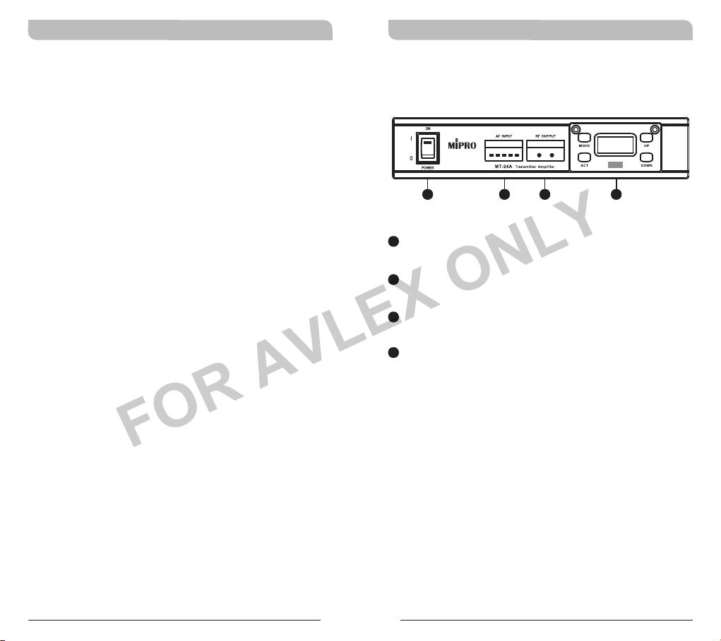
Power Switch & Indicator: Red indicator is
illuminated after power is turned on.
2
AF Signal Indicators: Indicate the input audio
signal level.
RF Signal Indicators: Indicate the output RF
3
signal level.
4
Wireless Transmitter Panel: Preset with
user-selectable 12 channels & 16 ID Codes.
2
3 4
CH - ID
10 - 15
0
1
Page 3
2.4 GHz Digital Stationary Transmitter 2.4 GHz Digital Stationary Transmitter
FOR AVLEX ONLY
Transmitter Panel
65
CH - ID
7
10 - 15
9
10
11
5
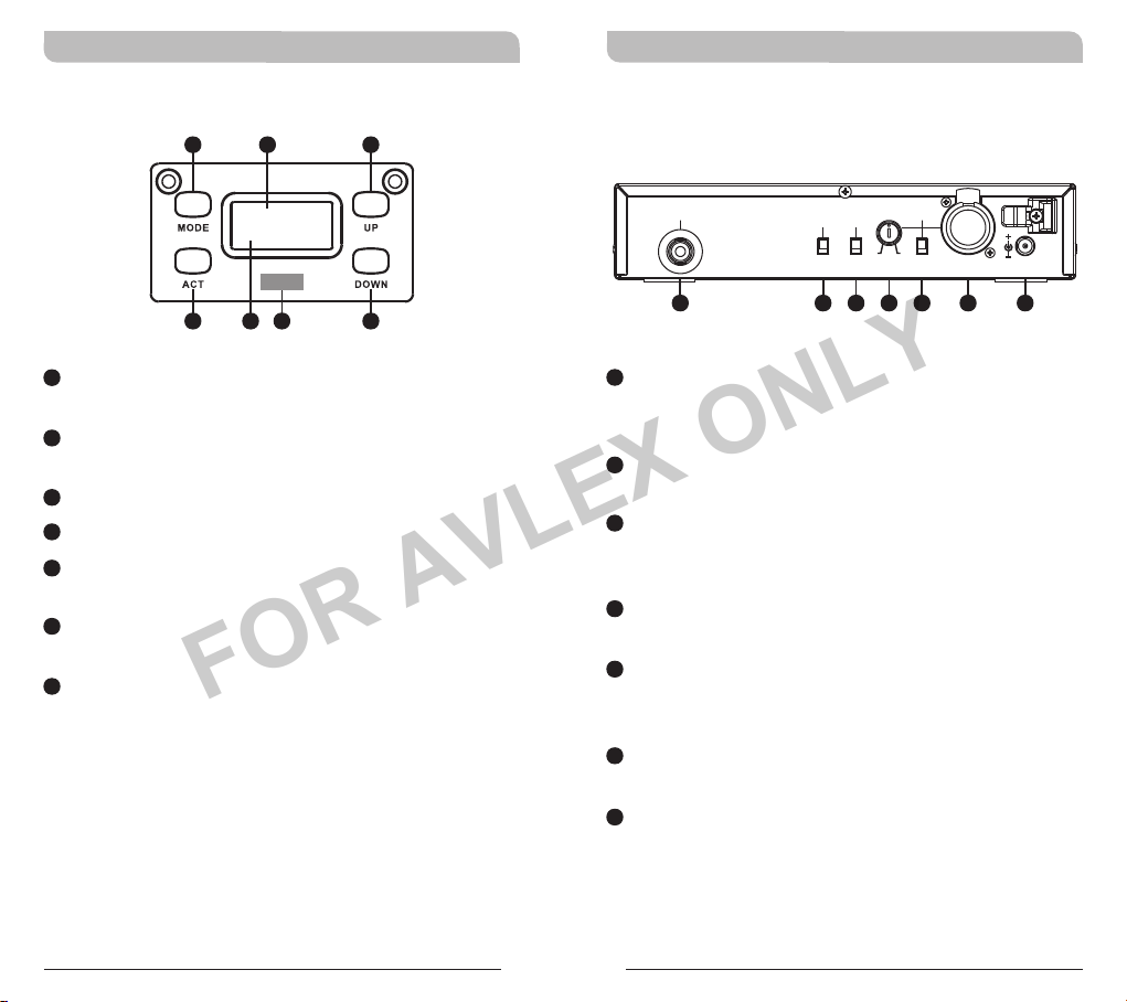
MODE button: To select CH (Channel) or ID (ID
Code) setup.
6
LCD Screen: Display CH (Channel) & ID (ID
Code).
7
UP button: Increase parameter value.
8
DOWN Button: Decrease parameter value.
9
ACT sync window: Synchronize the receiver
frequency automatically.
10
Parameter: Display the selected Channel and
ID Code numbers.
11
ACT button: Press this button to sync Channel
& ID Code with a MIPRO ACT-24R receiver.
8
Controls and Indicators
Rear Panel
ANTENNA
12
12
RF Output Connector: Connect directly to a
PHANTOM
RF
HIGH
OFFONLOW
13
transmitting antenna or extend to external
antenna by RF cable.
13
RF Output Switch: High or Low RF level
switch.
14
+48 Phantom Power Switch: Can be switched
to offer +48V Phantom power to wired
microphones or not.
15
AF Level Knob: Adjust to select the optimal
sensitivity without distortion.
16
AF Level Switch: MIC LEVEL(0dB) and LINE
LEVEL(-20dB) audio output for optimal
modulation index.
17
Combo Jack Connector: Balanced (XLR) or
unbalanced (1/4-inch) audio input signals.
18
DC Voltage Input Connector: 12~15V DC
voltage, the center pole of the DC connector is
positive voltage.
( +48V )
14
MIN MAX
15
AF INPUT
16
LINE
MIC
17
DC IN (12~15V)
18
2 3
Page 4

2.4 GHz Digital Stationary Transmitter 2.4 GHz Digital Stationary Transmitter
FOR AVLEX ONLY
Controls and Indicators
CH - ID
10 - 15
1. CH-ID Channel | ID Code
Channel Set-up Instructions:
1Press MODE button to activate setup mode
1Press UP or DOWN button to increase or
CH - ID
ID Code Set-up Instructions
1Press MODE button to activate setup mode
1Press UP or DOWN button to increase or
:
and until CH icon starts to flash.
decrease channel number during CH icon
flashing.
CH - ID
10 - 15
and until ID icon starts to flash.
decrease ID Code number during ID icon
flashing.
09 - 15
CH - ID
09 - 15
2. ACT Synchronization
Press ACT button to
CH - ID
10 - 12
ACT
FAIL
a. Power on transmitter and receiver. The infrared
sync windows of both transmitter and receiver
need to face and within 10cm (4-inch) of each
other before the ACT button is pressed. Press
ACT button to activate frequency
synchronization with a matching receiver. ACT
icon appears once ACT button is pressed. FAIL
icon appears when frequency synchronization is
performed unsuccessfully.
b. Once the frequency synchronization is performed
successfully. CH-ID with the selected reappears.
activate frequency
synchronization
with a matching
receiver
FAIL icon appears
with a failed
synchronization
CH - ID
09 - 15
CH - ID
CH - ID
09 - 14
09 - 14
4 5
Page 5

2.4 GHz Digital Stationary Transmitter 2.4 GHz Digital Stationary Transmitter
FOR AVLEX ONLY
3. ACT Synchronization with ACT-24R
receiver: Set-up Instructions
ACT Synchronization normally allows you
to automatically synchronize the frequency
selected for your receiver, to your
handheld and bodypack transmitters or in
certain specific device like MT-24A,
frequency selected for your transmitter, to
your receiver, all at a simple touch of a
button.
H i
CH - ID ACT
10- 15
ON
AF INPUT
RF OUTPUT
LOW HIGH
Transmitter Amplif ier
MT-24A
POWER
MT-24A
transmitter
CH - ID
10 - 15
ACT (Sync)
< 10cm (4 inch)
ACT-24R
receiver
4. ACT Synchronization with ACT-2400
series receivers and MRM-24 receiver
module Set-up Instructions
ACT Synchronization allows you to automatically
synchronize the frequency selected for your
receiver, to your handheld and bodypack
transmitters, at a simple touch of a button.
09
08
Lo
08
06
H
i
ACT-2400 Series
receiver
AF
L
NE
BT
CHAN
UME
FF
O
VOL
T
AC
SCAN
MA-808
ACT (Sync)
< 10cm (4 inch)
ACT (Sync)
< 10cm (4 inch)
ON
AF INPUT
RF OUTPUT
LOW HIGH
Transmitter Amplif ier
MT-24A
POWER
MT-24A
transmitter
ON
AF INPUT
RF OUTPUT
LOW HIGH
Transmitter Amplif ier
MT-24A
POWER
MT-24A
transmitter
CH - ID
10 - 15
CH - ID
10 - 15
MRM-24
receiver
6 7
Page 6

2.4 GHz Digital Stationary Transmitter 2.4 GHz Digital Stationary Transmitter
FOR AVLEX ONLY
Operating Tips
This transmitter has a higher power than the
average handheld or bodypack transmitters.
Interference may occur to wireless microphone
systems. Switch to a different transmitter channel if
interference occurs.
Proper RF Output Level and Output
Connector Settings
High or Low RF level switch is located at the rear
panel. Front panel will display current High or Low
RF output power setting.
ON
AF INPUT
ANTENNA
AF INPUT
PHANTOM
RF
( +48V )
HIGH
LINE
OFFONLOW
MIN MAX
MIC
DC IN (12~15V)
POWER
RF
HIGH
LOW
RF OUTPUT
LOW HIGH
Transmitter Am plifi er
MT-24A
RF OUTPUT
LOW HIGH
CH - ID
10 - 15
+48V Phantom Power Setting
+48V Phantom Power is available from the combo
jack connector. Use the +48V Phantom Power
Switch at the rear panel to active this function.
ANTENNA
OFF
PHANTOM
RF
( +48V )
HIGH
OFFONLOW
PHANTOM
( +48V )
ON
MIN MAX
AF INPUT
LINE
MIC
DC IN (12~15V)
8 9
Page 7

2.4 GHz Digital Stationary Transmitter 2.4 GHz Digital Stationary Transmitter
FOR AVLEX ONLY
Proper AF (audio) Input and Connection
! Combo jack connector accepts balanced (XLR)
or 1/4-inch(6.3mm) unbalanced cable.
! Proper input volume adjustment is needed after
AF signal is connected.
! Two selectable AF levels (MIC/LINE) can be
OUT
OUT
OUT
16
CUT
T.H.D
CUT
S/N
Optimum
selected from AF Level Switch for optimal
audio sensitivity. Exceeding input volume will
result in distortion for receiver AF output, and
insufficient input volume will degrade the S/N
ratio that increases higher background noise.
RF, proper setting ensures optimal output audio
quality.
Exceeding Input
+Clamp
0
-Clamp
Optimal Input
Insufficient Input
Optimal AF Input Volume Setting
! The AF Signal Indicators indicates the input
audio signal level.
! Normal volume: 2~3 LEDs are illuminated.
! High volume: 4 LEDs are illuminated.
! Peak volume: Red Limit indicator will be
illuminated to denote warning.
AF INPUT
G G G G
NORMAL
MIN
G
MAX
! When 4~5 LEDs are illuminated constantly it
denotes exceeding input volume and input
attenuation is required. Switch the input volume
16
switch to -20dB or adjust the AF Level Knob
counterclockwise for modification.
AF INPUT
G G G G
ON ON ON ON ON
AF INPUT
G
! When 1~2 LEDs are illuminated constantly it
denotes insufficient input volume and less input
attenuation is required. Switch the input volume
16
switch to 0dB or adjust the AF Level Knob
clockwise for modification.
AF INPUT
AF INPUT
2
AF INPUT
LINE
MIC
Switch to LINE
AF INPUT
CH - ID
10 - 15
LINE
or
MIC
Rotate
counterclockwise
MIN MAX
15
15
G G G G
10 11
ON ON
G
LINE
MIC
Switch to MIC Rotate clockwise
LINE
MIC
or
MIN MAX
Page 8

2.4 GHz Digital Stationary Transmitter 2.4 GHz Digital Stationary Transmitter
FOR AVLEX ONLY
Federal Communication Commission Interference
Statement
This equipment has been tested and found to comply with
the limits for a Class B digital device, pursuant to Part 15
of the FCC Rules. These limits are designed to provide
reasonable protection against harmful interference in a
residential installation. This equipment generates, uses and
can radiate radio frequency energy and, if not installed and
used in accordance with the instructions, may cause
harmful interference to radio communications. However,
there is no guarantee that interference will not occur in a
particular installation. If this equipment does cause harmful
interference to radio or television reception, which can be
determined by turning the equipment off and on, the user
is encouraged to try to correct the interference by one of
the following measures:
Reorient or relocate the receiving antenna.
!
Increase the separation between the equipment and
!
receiver.
Connect the equipment into an outlet on a circuit
!
different from that to which the receiver is connected.
Consult the dealer or an experienced radio/TV technician
!
for help.
FCC Caution: To assure continued compliance, any
changes or modifications not expressly approved by the
party responsible for compliance could void the user's
authority to operate this equipment. (Example - use only
shielded interface cables when connecting to computer or
peripheral devices).
FCC Radiation Exposure Statement
This equipment complies with FCC RF radiation exposure
limits set forth for an uncontrolled environment. This
equipment should be installed and operated with a
minimum distance of 0.5 cm between the radiator and your
body.
12 1 3
This transmitter must not be co-located or operating in
conjunction with any other antenna or transmitter.
The antennas used for this transmitter must be installed to
provide a separation distance of at least 0.5 cm from all
persons and must not be co-located or operating in
conjunction with any other antenna or transmitter.
This device complies with Part 15 of the FCC Rules.
Operation is subject to the following two conditions:
(1) This device may not cause harmful interference, and
(2) This device must accept any interference received,
including interference that may cause undesired operation.
IC
This device complies with Industry Canada RSS-210
ISSUE 2 standards. Operation is subject to the following
two conditions:
(1) this device may not cause interference, and
(2) this device must accept any interference, including
interference that may cause undesired operation of the
device.
Le présent appareil est conforme aux CNR d'Industrie
Canada applicables aux appareils radio exempts de licence.
L'exploitation est autorisée aux deux conditions suivantes:
(1) l'appareil ne doit pas produire de brouillage, et
(2) l'utilisateur de l'appareil doit accepter tout brouillage
radioélectrique subi, même si le brouillage est susceptible
d'en compromettre le fonctionnement.
Notes
1. Refer to actual product in the event of product
description discrepancy.
2. Frequency range and maximum deviation comply with
the regulations of different countries.
Page 9

2.4 GHz Digital Stationary Transmitter 2.4 GHz Digital Stationary Transmitter
FOR AVLEX ONLY
WARNING
1. FOR OUTDOOR USE:
To reduce the risk of fire or electric shock, do not expose
this apparatus to rain or moisture.
2. UNDER WET LOCATION:
Apparatus should not be exposed to dripping or splashing
and no objects filled with liquids, such as vases should be
placed on the apparatus.
3. SERVICE INSTRUCTIONS:
CAUTION - These servicing instructions are for use by
qualified service personnel only. To reduce the risk of
electric shock, do not perform any servicing other than that
contained in the operating instructions unless you are
qualified to do so.
This symbol indicates that dangerous voltage
constituting a risk of electric shock is present within
this unit.
This symbol indicates that there are important
operating and maintenance instructions in the
literature accompanying this unit.
Disposal
2005 -08-1 3
Dispose of any unusable devices or batteries
responsibly and in accordance with any applicable
regulations.
Disposing of used batteries with domestic waste is
to be avoided!
Batteries / NiCad cells often contain heavy metals
such as cadmium(Cd), mercury(Hg) and lead(Pb)
that makes them unsuitable for disposal with
domestic waste. You may return spent batteries/
accumulators free of charge to recycling centres or
anywhere else batteries/accumulators are sold.
By doing so, you contribute to the conservation of
our environment!
14 1 5
! IMPORTANT SAFETY INSTRUCTIONS !
1. Read these instructions.
2. Keep these instructions.
3. Heed all warnings.
4. Follow all instructions.
5. Do not use this apparatus near water.
6. Clean only with a dry cloth.
7. Do not block any ventilation openings. Install in accordance
with the manufacturer's instructions.
8. Do not install near any heat sources such as radiators, heat
registers, stoves, or other apparatus (including amplifiers)
that produce heat.
9. Do not defeat the safety purpose of the polarised or ground
plug: A polarised plug has two blades with one wider than
the other. The wide blade is provided for your safety. When
the provided plug does not fit into your outlet, consult an
electrician for replacement of the obsolete outlet.
10. Protect the power cord from being walked on or pinched
particularly at plug, convenience receptacles, and the point
where they exit from the apparatus.
11. Only use attachments/accessories specified by the
manufacturer.
12. Use only with a cart, stand, tripod, bracket, or
table specified by the manufacturer, or sold
with the apparatus. When a cart is used, use
caution when moving the cart/apparatus
combination to avoid injury from tip-over.
13. Unplug this apparatus during lightning storms or when
unused for long periods of time.
14. Refer all servicing to qualified service personnel. Servicing is
required when the apparatus has been damaged in any way,
such as power-supply cord or plug is damaged, liquid has
been spilled or objects have fallen into the apparatus, the
apparatus has been exposed to rain or moisture, does not
operate normally, or has been dropped.
15. To reduce the risk of fire or electric shock, do not expose
this apparatus to rain or moisture.
16. Apparatus should not be exposed to dripping or splashing
and no objects filled with liquids, should be placed on the
apparatus.
17. Use only with the battery which specified by manufacturer.
18. The power supply cord set is to be the main disconnected
device.
 Loading...