

Page 1
Disposal
Disposetheunusabledeviceaccordingtovalidregulations.
Disposalofspentbatteries/accumulators
Youarerequiredbylawtoreturnallspentbatteries.
Disposingofusedbatterieswithdomesticwasteis
prohibited!
Batteries/NiCadcellscontainingtoxinsare
markedbyaccompanyingsymbolsthatreferto
theprohibitionofdisposalwithdomesticwaste.
Thedesignationsforthedecisiveheavymetals
are:=cadmium,=mercury,=lead.You
CdHgPb
2005-08-13
Bydoingso,youfulfilthelegalrequirementsand
contributetotheconservationofourenvironment!
mayreturnspentbatteries/accumulatorsfreeof
chargetotherecyclingcentres,ouroutletsor
anywhereelsewherebatteries/accumulatorsare
sold.
OPERATINGMANUAL
MR-801Half19-inchunit
UHFWirelessMicrophoneSystem
ElectronicsCo.,Ltd.
Headoffice:814,Pei-KangRoad,Chiayi,600,Taiwan.
Taipeioffice:5,Lane118,Sung-tehRoad,100,Taipei,Taiwan.
Web-http://www.mipro.com.tw
E-mail:@mipro.com.twmipro
2CE126
Page 2
WIRELESSRECEIVER
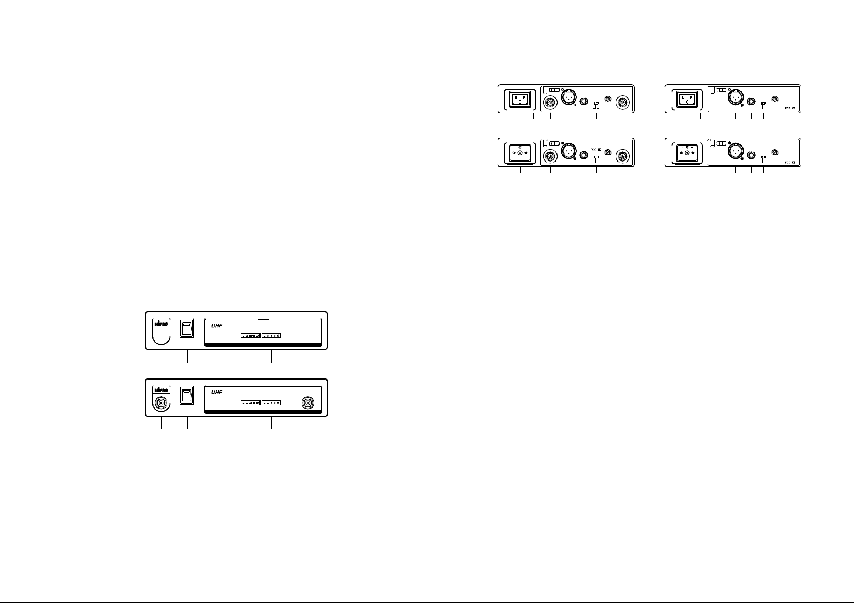
B.RearPanel
ThankyouforselectingMIPROUHFhalf19-inchunittruediversity
wirelessreceiversystem.Beforeoperatingpleasereadthisinstruction
manualcarefullyandthoroughlyinordertoattainthecorrectoperating
proceduresandachievethebestresults.
ThissystemisdividedintoUHFsinglechanneltruediversity
receiverwithmatchingonemicrophonesandindividualvolumecontrols.
Thissystemisalsoequippedwith"PILOTONE"andthelatest"NOISE
LOCK"dual-squelchcircuit,andprovidestheefficacyforeliminatethe
randomnoiseinterferencewhenthereceiverisatstandbystate.
Thissystemincludesthefollowingaccessories:
①×AudioOutputCable1
③×Antenna2
④×AC/DCAdapter1orPowerCablex1
②×InstructionManual1
1.PartsNameAndFunctions
A.FrontPanel
(Antennainrear)
POWER
(2)
(Antennainfront)
POWER
TRUEDIVERSITYWIRELESSRECEIVER
MR-801 SIGNAL AUDIO
(3) (4)
TRUEDIVERSITYWIRELESSRECEIVER
MR-801 AUDIO
SIGNAL
ANT.B
(Withswitching
powersupply)
-
(7)
(Antennainrear)
UNBALANCEDOUT
ANT.B
MIC
BALANCEDOUT
(8) (10)(9) (13)(12)(11)
(6)
+
UNBALANCEDOUT
ANT.B
MIC
BALANCEDOUT
(8) (9) (10) (13)(12)(11)
SQ
ANT.A
LEVEL
LINE
(Withswitching
powersupply)
SQ
ANT.A
LEVEL
LINE
(Antennainfront)
UNBALANCEDOUT
BALANCEDOUT LINEMIC
(6)
(7) (9) (10) (12)(11)
(10)(9) (12)(11)
UNBALANCEDOUT
BALANCEDOUT
LEVEL SQ
LEVEL SQ
LINEMIC
(Fig.2)
(6)ACInputJack:Toconnect85~265VoltsACpower.
(7)DC12VInputJack:Toconnect12VDCfromtheAC/DCadapter.
(8)AntennaInputConnectors:ForRearAntennaPlacement.
(9)BalancedAudioOutputJack:WithCannon/XLRtypeconnector
providesbalancedaudiooutputsignalfromthisjacktotheamplifier.
(10)UnbalancedAudioOutputJack:With1/4"PhoneJackprovides
audiooutputsignalfromthisjacktotheamplifier.
(11)UnbalancedLevelSwitch:"MIC"selectionisfor"Microphone-level"
output."LINE"selectionisfor"Line-out"leveloutput.
(12)SquelchAdjusters:Adjustthe squelchleveltoeliminatetheRF
noiseinterferenceatreceiverstand-bystate.
(13)AntennaInputConnectors:ForrearAntennaPlacement.
(2)(1) (3) (5)
(4)
(Fig.1)
(1)AntennaInputConnector:ForFrontAntennaPlacement.
(2)PowerSwitch&Indicator:Whenswitchisturnedon,redindicator
illuminatestodenotenormalpowerstatus.
(3)RFSignalIndicator:IndicatesreceivingtransmittingRFsignals.
(4)AudiosignalIndicator:Indicatesthemicrophonesignal.
(5)AntennaInputConnector:ForFrontAntennaPlacementofdual
channel.
-2--1-
Page 3
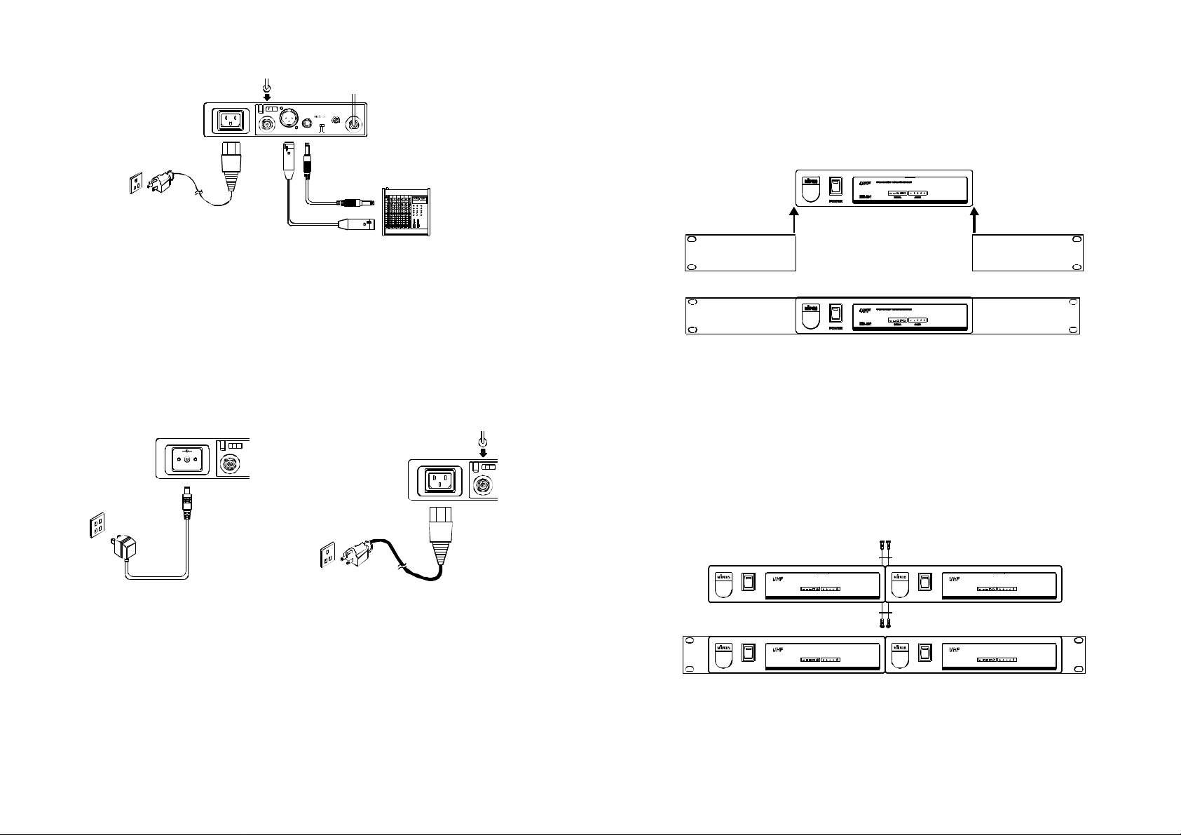
2.InstallationOfTheReceiver
3.RackMounting
UNBALANCEDOUT
ANT.B
BALANCEDOUT
SQ
ANT.A
LEVEL
LINE
MIC
(Fig.3)
1.Installantennainrear(8)(13)oratthefront(1)(5).Extendantenna
tothefullestposition.seefig.3.
2.PowerOutputConnection:
(a)ConnecttheAC/DCadaptercabletoDC12VINPUTJACK(7),
thenplugtheadapterunitintoanappropriateACoutletwith
cautiontothecorrectvoltageunderbothACoutletandadapter
marked,asshowninfig.4.
(b)WiththeappropriateACpowercableconnectsfromACInput
Jack(6)toanACoutletunderthemarkedvoltage85~265V,as
showninfig.5.
+
-
ANT.B
ANT.B
1.Singlehalf-rackreceiver
(a)Pushtherackmountearoptionalaccessory(FB-11)upwards
untilitisfirmlyattachedtothereceiver.(fig.6)
(Fig.6)
2.Dualhalf-rackreceivers
(a)Positiontheconnectingplatesbetweenthetopandbottomofthe
tworeceiversandtighten.(Fig.7)
(b)Afterjoiningthe2receiverstogether,pushtheoptionalaccessory
rackmountears(FB-12)upwardsuntiltheyfirmlyattachedtothe
receiver.(Fig.7)
(Fig.4)
3.AudioOutputConnection:
(a)UnbalancedLevelSwitch(11)SettingPosition:Wheninputsthe
unbalancedoutputofareceiverinto"Line-in"inputjackofa
mixeroramplifieror"ElectricGuitar",switchtheLevelSwitch(11)
totheright"LINE"position.Lowsensitivitymayoccurifswitch
tothewrongposition.Wheninputtheunbalancedoutputofa
receiverintothe"MIC-IN"inputjackofamixeroramplifier;
switchtheLevelSwitch(11)totheleft"MIC"position.Overload
distortionmayoccurifswitchtothewrongposition.Whenusing
electricguitar,don'tuse"MIC"positionasitmayhave
generatedinsufficientlevel.
(Fig.5)
POWER
POWER
TRUEDIVERSITYWIRELESSRECEIVER
MR-801 SIGNAL AUDIO
TRUEDIVERSITYWIRELESSRECEIVER
MR-801 SIGNAL AUDIO
TRUEDIVERSITYWIRELESSRECEIVER
MR-801 SIGNAL AUDIO
POWER
TRUEDIVERSITYWIRELESSRECEIVER
MR-801 SIGNAL AUDIO
POWER
(Fig.7)
-4--3-
Page 4
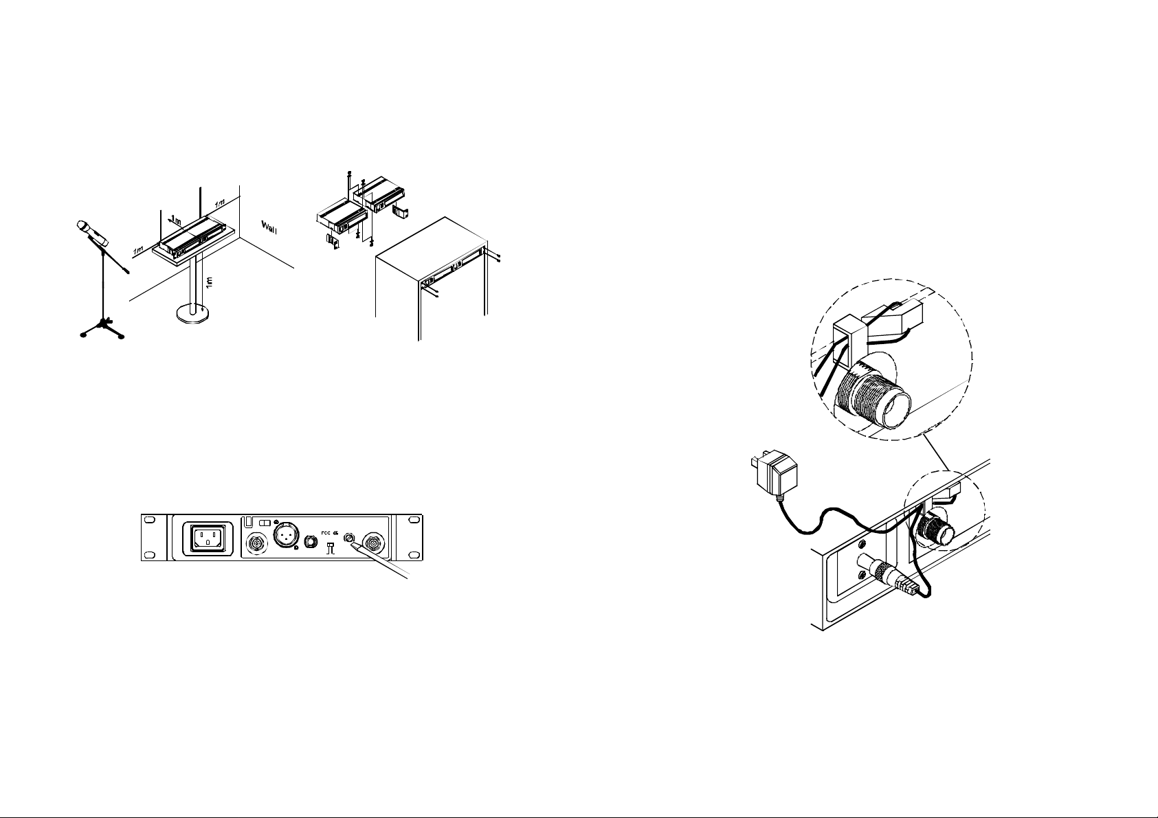
3.Makesurethatthesystemperformscorrectlybyplacingthesystem
awayfromnoisesources.Placethereceiveratleast1meterabove
thegroundandawayfromnoisesources.Placethemicrophoneat
least1meterawayfromthereceivingantenna,asshowninFig.8.
4.Aftercompletion,itcanberackmountedintoanEIAstandardrack
case,asshowninFig.9.
Ground
(Fig.8) (Fig.9)
4.OperationInstructions
1.Turnvolumecontrolsofthereceiverandmixerinusetoaminimum
settingbeforeturnonthemicrophonesortransmitters.After
switchesonthereceiver,thepowerswitchredindicatorilluminates
todenotenormalpowerstatus.
3.Undernormalcircumstances,theSIGNALindicatorlightsupwhena
microphoneortransmitteristurnedonnearthereceivertoindicate
thereceiverisreadyfornormaloperation.Oncesoundstothe
microphoneandtheAUDIOLEDindicators(4)willglowaccordingto
thestrengthofsoundlevel.IfnoLEDglowsornosoundoutputs,
thesystemisnotfunctionproperly,thusitmustbechecked.
4.Themicrophoneoutputlevelneedstobeadjustedattheamplifieror
mixer.Noneedtoadjustatthereceiveritself.
5.Plugthecableofthemainsunitintodcsocketonthereceiver's
backpanel.Threadthecablethroughthecablegripasshownon
theaboveillustration.Thecablegrippreventstheconnectorfrom
beingpulledoffbyaccident.
ANT.B
UNBALANCEDOUT SQ
LEVEL
BALANCEDOUT MIC LINE
ANT.A
(Fig.10)
2.IfSIGNALLEDindicators(3)ofthereceiverlightonbeforeswitches
onthemicrophoneortransmitter,itindicatesthereceiverisreceiving
interferencesignals.ThissystemhasPitlotoneandNoiseLockdualsquelchfeaturesandnonoiseoutputwilloccur.Ifmultiplechannels
areusedandbothSIGNALandAUDIOLEDsglowandinterference
noiseappear,simplyadjusttheSquelchcontrols(12)clockwiseuntil
AUDIOsignalindicatorstoextinguish.(Fig.10).However,by
adjustingthesquelchcontrols,itaffectsthesensitivitylevelofthe
receiver,therefore,shortentheoperatingdistanceanddecreasesthe
stability.
(Fig.11)
-6--5-
Page 5

5.Caution
HANDHELDWIRELESSMICROPHONE
1.Sincetheinstallationofantennainfluencestheoperatingefficiencyof
thereceiver,themostimportantruleistominimizedthedistance
betweenreceivingantennaandmicrophoneasshortaspossiblefor
betterreceptionandperformance.
2.TheexternalDCpowersupplyshouldnotbebelow12V,otherwiseit
wouldnotworkproperly.Ifitisover15V,somecomponentsofthe
receiverwillbedamagedduetohighercurrent.Useminimum1A
powersupply.
3.Thissystemutilizescomputertransformer.Itisequippedwith85~
265Vswitchingpowersupplytoavoidswitchinganditisnotaffected
bypowerinstability.
Themicrophoneismodularindesign.(1)Grille(2)Anti-Rolling
ColoredRing(3)Cartridge(4)Housing(5)BatteryStatusIndicator(6)
PowerOn-OffSwitch(7)BatteryCompartment(8)BatteryCap.Italso
incorporates"NoiseLock"dual-squelchcircuitrytoeliminateinterference.
1 32 654 87
(Fig.1)
1.PartsNameAndFunctions
1.Grill:Protectscartridgeandprevents"POP"noise.
2.Anti-RollingColoredRing:Forfrequencyidentification.Itspolygonal
shapealsopreventsthemicrophonefromrollingwhenplacedona
flatsurface.
3.Cartridgeormicrophoneelement/insert.
4.Housing:Upperportionisconnectedtocapsulemodule.Internally,it
housesthetransmitterPCBandbatterycompartment.
-7-
5.BatteryStatusIndicator:Indicatespoweron/offandthebattery
status.WhenthepowerswitchisturnedON,theredLEDsindicator
flashesbriefly,indicatingnormalbatterystatus.Ifnoflashoccurs,it
haseithernobatteryorthebatteryisdischargedorinstalled
incorrectly.Ifafterpowerontheindicatorstayslighted,itwarnsthat
thebatteryisweakandshouldbereplaced.
6.PowerOn-offSwitch:Slidetheswitchforpower"ON"or"OFF".
7.BatteryCompartment:Designedtoaccommodateone9Vbattery.
8.BatteryCap:Coversthebatterycompartment.
-8-
Page 6

2.BatteryInsertion
HANDHELDWIRELESSMICROPHONE
ThismicrophoneutilizesadvancedmodularassemblyandPLL
synthesizeddesign.Preprogrammedwith30frequenciesallowstheuser
tofreelyselectnon-interferencechannels.Italsoincorporates"Pilotone
&NoiseLockdual-squelch"toeliminatenoiseinterference.
(Fig.2)
1.Unscrewbatterycapinacounter-clockwisedirection(8).
2.Inserta9Vbatteryintothebatterycompartmentaccordingtothe
correctpolarityasshowninFig.2.Themomentthebatterytouches
theterminals,theindicatorwillflashbriefly(8).Thismeansthe
polarityiscorrect.However,ifnoflashoccurs,thisindicateswrong
insertionorthatthebatteryisdead.Pleasere-insertthebattery
accordingtoitscorrectpolarityorexchangeitforafreshbattery.
3.OperatingInstructions
1.Whenmicrophoneisswitchedon:
Whenthepowerisswitchedon,theindicatorwillflashbriefly
indicatingnormaloperation.
2.Aftermicrophoneisswitchedon:
TheSIGNALLEDindicator(3)onreceiverglows.ThemoreLEDs
thatglowindicatethatthereceivedsignalstrengthisstronger.If
onlytheredLEDilluminatesitindicatesabnormalreceivingstatus
andinsufficientsignalstrength.
3.DuringUsage:
TheAUDIOLEDindicator(4)onthereceiverwillilluminateaccording
totheaudiosignalstrengthfromthemicrophone.WhentheredLED
isON,itindicatesthatmaximumsoundpressurelevelhasbeen
reachedbutdoesnotrepresentdistortion.
4.Whenthemicrophoneisnotinuse:
Makesurethatyouturnoffthemicrophoneafterusetoextendthe
batterylife.Removethebatteryfromthebatterycompartmentif
microphoneisnottobeusedagainforsometime.Ifarechargeable
batterywasused,takeitoutandrechargeit.
1.PartsNameAndFunctions
321
4
1.Grille:Protectscartridgeandprevents"POPnoise.
2.RollingProofColorRing:Forfrequencydifferentiationandits
polygonalshapepreventsmicrophonefromrolling.
3.BatteryCompartment:Designedtoaccommodateonepiece9V
battery.
4.Housing:Upperportiontobeconnectedtocapsulemoduleand
battery.Internally,itholdstransmitterPCB.
5.BatteryStatusIndicator:Indicatesthepoweron/offandbattery
status.WhenpowerswitchisturnedON,theredLEDsindicator
flashesbriefly,indicatingnormalbatterystatus.Ifnoflashoccurs,it
haseithernobatteryorthebatteryisdrainedorinstalledincorrectly.
Afterpoweronandtheindicatorstayslighted.Itwarnsthebattery
isweakandanewbatteryreplacementisthusnecessary.
6.PowerOn-offSwitch:Slidetheswitchforpower"ON"or"OFF".
65
(Fig.1)
-9-
-10-
Page 7

2.BatteryInsertion
BELTPACKTRANSMITTER
1.PartsNameAndFunctions
MICANT.
1
(Fig.2)
1.Unscrewbatterycapincounter-clockwisedirection(Fig.2).
2.Inserta9Vbatteryintothebatterycompartmentaccordingtothe
correctpolarityasshowninFig.2.Themomentthebatterytouches
theterminalsofcompartment,theindicator(5)willflashbriefly.This
meansthepolarityiscorrect.However,ifnoflashoccurs,this
indicateswronginsertion.Pleasere-insertthebatteryaccordingtoits
correctpolarity.
3.OperatingInstructions
1.Whenmicrophoneisswitchedon:
Atthemomentofthepowerisswitchedon,theindicatorwillflash
brieflyindicatingnormaloperation.
2.Aftermicrophoneisswitchedon:
TheSIGNALLEDindicator(3)ofreceiverglows.ThemoreLED
glowsindicatingreceivedsignalstrengthisstronger.IfonlyredLED
illuminatesitdenotesabnormalreceivingstatus.
3.DuringUsage:
TheAUDIOLEDindicator(4)ofthereceiverwillilluminateaccording
tothesoundstrengthinputtothemicrophone.Whenapproaching
redLEDlightson,itdenotesthemaximumsoundpresslevelbut
doesnotrepresentdistortion.
4.Whenthemicrophoneisnotinuse:
Makesuretoturnoffthemicrophonetoextendthebatterylife.
Removethebatteryfromthebatterycompartmentifmicrophoneis
notinused.Ifarechargeablebatterywasused,takeitoutand
inserttothebuilt-inbatterychargeronthereceiverforrecharge.
2
3
4
5
9
6
7
OFF ON
BATT.LOW
8
1.4-PinJackInputConnector:Connectto4-pinconnector.Allows5
differentinputs.(See5waysofconnectiononAFInputConnections
laterinthisbooklet).
2.TransmittingAntenna:1/4transmittingantenna.
λ
3.GT/MTSwitch:SwitchtotheGTpositionforelectricguitarusage
ONLY.TheGainControlisbypassedin"GT"mode.Switchtothe
"MT"forcondensermicrophone,wiredmicrophoneorLine-in.The
GainControloperatesinthe"MT"modeforadjustinginputsensitivity.
4.GainControl:Adjuststheinputgain.Pleasetakecarenotto
inadvertentlyturntheleveldownforalossofsignal,oruptoinduce
feedback.
-11-
-12-
Page 8

5.TransmitterHousing:HousesthePCBandbattery.
6.BatteryStatusIndicator:Indicatesthepoweron/offandbattery
status.
(a)WhenpowerswitchisturnedontheLEDindicatorflashesbriefly,
indicatingnormalbatterystatus.
(b)WhentheREDlightilluminatesateitherpoweronorduringuse,
itindicatesthatthebatterylevelislow,thereforeanewbatteryis
required.
7.PowerSwitch:SwitchtotheONpositionforoperation.Switchtothe
OFFpositionwhennotinuse.
8.BatteryCompartmentandCover:Accommodatesone9Vbattery.
9.DetachableBeltClip:Pullslightlytowardsyou andpushdown
accordingtothearrowdirectiontoreleasethebeltclip.
2.OperatingInstructions
1.Pushdowntoopenthebatterycompartmentcover(8)asshownin
Fig.1.
2.Inserta9Vbatteryintothebatterycompartmentaccordingtothe
correctpolarityasshowninFig.2.Thenpushuptoclosethe
batterycompartmentasshowninFig.3.
3.TheLEDindicatorflashesbrieflyatpoweronindicatingnormal
batterystatus.Ifnoflashoccursithaseithernobattery,thebattery
isdrainedorisinstalledincorrectly.Changeaccordingly.
4.4-PinJack:VolumecanbeadjustedviatheGaincontrol.TheGain
controlhasnoeffectwhenswitchedtoGT(Guitar)usage.
5.4-PinJack:Alignandinserttheplugtojackaccordinglyandtighten
itintheclockwisedirectionasshowninfigure4.
CapsuleConnectort
Headset
Lavalier
Pleaseaimofthefillister
andinserttheconnector
(Fig.4)
OFF ON
BATT.LOW
(Fig.1) (Fig.2) (Fig.3)
-13-
-14-
Page 9

3.AF4-PinInputConnectionMethod
BELTPACKTRANSMITTER
(1)2-WireElectretcondensermicrophoneCapsule
PIN
SHIELD
AUDIO
1
2
1 4
2 3
3
4PIN
4
PLUG
(2)3-WireElectretcondensermicrophoneCapsule
PIN
SHIELD
AUDIO
BIAS
1
2
1 4
2 3
3
4PIN
PLUG
4
(3)DynamicMicrophone
PIN
2 1
3
SHIELD
AUDIO
1
2
1 4
2 3
3
4PIN
4
PLUG
(4)ElectricGuitar
PIN
SHIELD
AUDIO
1
2
1 4
2 3
3
4PIN
4
PLUG
(5)Line-in(Impedance8KATT.10dB)Ω
PIN
SHIELD
AUDIO
1
2
1 4
2 3
3
4PIN
4
PLUG
-15- -16-
1.PartsNameAndFunctions
(XLRJACK)
10
1.AFInputJack:Connectstoeitherlavaliereorheadsetmicrophone.
(See5waysofconnectiononAFInputConnections)
2.PowerSwitch:SwitchtoONpositionforoperation.SwitchtoOFF
positionwhennotinuse.
3.BatteryStatusIndicator:Indicatesthepoweron/offandbattery
status.
(a)Whenpowerswitchisturnedon:TheLEDindicatorflashes
briefly,indicatingnormalbatterystatus.
(b)WhenREDlightilluminatesateitherpoweronorduringusage:
Thebatterylevelislow,therefore,anewbatteryreplacementisthus
necessary.
4.TransmittingAntenna:1/4transmittingantenna.
λ
5.TransmitterHousing:PackagesthePCBandbattery.
6.UnusedStatusIndicator:WhenLEDlightson,itdenotesuntransmittedsignals.
7.GainControl:Adjuststhedesirousinputgain.
8.GT/MTLevelSelectSwitch:SwitchGTpositionforelectricguitar
usageONLY.GainControlisirrelevantfor"GT".Switchto"MT"for
condensermicrophone,wiredmicrophone.GainControlworksin
"MT"forinputsensitivityadjusting.
1
2
3
4
5
6
7
8
9
(Fig.1)
Page 10

9.BatteryCompartmentandCover:Accommodatesonepiece9V
battery.
10.DetachableBeltClip:Allows360degreesrotatingtosuittransmitting
angles.Todetachsimplyuseascrewdriverata45degreeangleto
unfasten.seediagram.
2.OperatingInstructions
1.Toadjustvolume(7),GT/MTSwitch(8),andreadtheunused
indicator(6),simplypushdownbothsnaplocksonthesidesof
batterycoverandflipitbackwardstoexposetheadjustmentpanel.
2.TheLEDindicatorflashesbrieflywhenpoweronindicatingnormal
batterystatus.Ifnoflashoccursithaseithernobattery,thebattery
isdrainedorinstalledincorrectly.Changeaccordingly.
3.AdjustGainControltodesiredvolume.(GainControlisirrelevant
whenswitchtoGTposition).
4.Plugthemicrophoneconnectorintotheinputjack(1)andtightenthe
connectorscrewbyclockwisedirectionasshownin(Fig.2).
CapsuleConnectort
Headset
Lavalier
Pleaseaimof
thefillister
andinsertthe
connector
3.Af4-pinInputConnectionMethods
(1)2-WireElectretcondensermicrophoneCapsule
PIN
SHIELD
AUDIO
(2)3-WireElectretcondensermicrophoneCapsule
SHIELD
AUDIO
BIAS
(3)DynamicMicrophone
2 1
3
SHIELD
AUDIO
(4)ElectricGuitar
SHIELD
AUDIO
(5)Line-in(Impedance8KATT.10dB)Ω
PIN
PIN
1
2
3
4PIN
4
PLUG
PIN
1
2
3
4PIN
4
PLUG
1
2
3
4
4PIN
PLUG
1
2
3
4PIN
4
PLUG
(Fig.2)
SHIELD
AUDIO
PIN
1
2
3
4PIN
PLUG
4
Page 11

4.BatteryInstallation
1.Pushingdownbothsnaplocksonthesidesofbatterycovertoopen
batterycover.Takeoutthebatteries.Fig.(3).
2.Inserta9Vbatteryintothebatterycompartmentaccordingtothe
correctpolarityasshowninFig.(4).Thenpushuptoclosethe
batterycompartmentasshowninFig.(4).
(Fig.3)
NOTE﹕
(Fig.4)
 Loading...