

Page 1

INSTRUCTION MANUAL
Please read this instructions carefully before use
Thank you for purchasing Minoura Magturbo Basic trainer.
This is the best cost-performance stationary indoor bicycle trainer
with completely re-designed patented magnetic resistance device
that allows you to feel real road ride feel even in your house or
garage.
This trainer fits between 24” to 27” (700c) wheels with adjusting the
roller position.
If you want to ride MTB on this trainer, we strongly recommend to
replace the rear tire from knobby one to a slick one in order to avoid
vibration and noise problem caused by the tire pattern.
- 1 -
Page 2
IMPORTANT NOTES
• Read all instructions carefully before use.
• Some assembly required.
• Keep the manual handy at all times. Lost instruction materials can be
replaced through Minoura or your local dealer.
• Do NOT use trainer for any other purpose than instructed.
• The trainer is manufactured to precise standards. You may not disassemble or rebuild it.
• "Magturbo" is the trademarks of Minoura and may not be copied.
WARNING
Use two-wheeled bicycles only. Tandems may be used if balanced correctly.
!
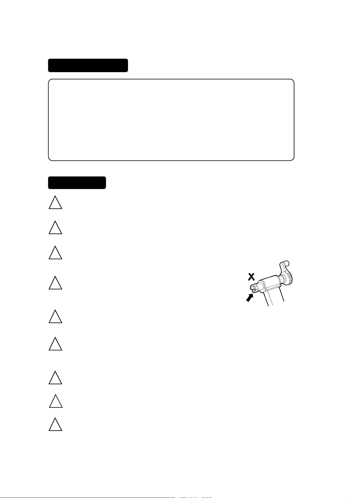
Remove all oils and moisture from the drive roller before use.
!
Keep both hands on handlebars at all times and maintain a normal riding
!
position.
Check the couplings supporting the rear hub for damage
!
and cracks. Accidents may occur from cracked or damaged
couplings.
When using the trainer, place it on a flat surface for safe training.
!
Do not over tighten the hub-clamp handles. Over-tightening may cause
!
damage to the trainer or bicycle frame. The clamp handles should be a snug
and secure fit. Do not force!
Please obey warning signs.
Keep away from small children.
!
Before use, make sure all bolts and nuts are securely fastened.
!
Keep hands and feet away from spinning rollers and wheels at all times.
!
- 2 -
Page 3
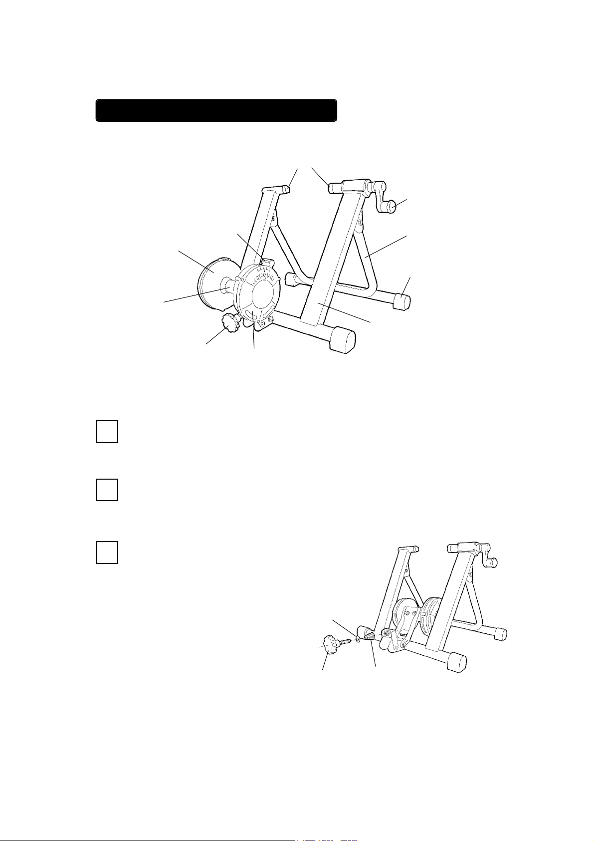
ASSEMBLING YOUR TRAINER
Coupling
Adjust
Lever
Flywheel
Housing
Drive
Roller
Hub Handle
U-Leg
Foot Cap
Frame
Micro Adjust
Knob
Open the Frame and U-Leg and place on level floor.
1
Tighten the Micro Adjust Knob Bolt with a spring
2
and a flat washer. (see Fig. B)
That’s all. Now you are ready to install your bike
3
on the trainer.
Mag Resistance
Unit
Flat
Washer
(Fig. A)
Knob Bolt
- 3 -
Spring
(Fig. B)
Page 4

INSTALLING YOUR BICYCLE
Before attaching your bicycle to this trainer, turn the Hub Handle in a counter-
1
clockwise direction to open the trainer enough to easily line up your rear quick
release (QR) with the Couplings. This will make it easier to attach the rear hub
of your bicycle.
Do NOT oepn the Hub Handle too far. Otherwise the inside Nylon nut located
in the metal cap of the Hub Handle may come loose.
Loosen the Knob Bolt enough until the wheel can be placed without touching
2
the Drive Roller on Mag resistance unit. You may need to manually move the
drive roller. This is O.K. and won't hurt the mag unit.
Install the rear hub between the couplings. (see Fig. C)
3
While holding your bicycle, tighten the Hub Handle in a clockwise direction
until you see the couplings come in contact, and engage the heads of your QR
lever.
Stop tightening the handle after the couplings have engaged the Q/R.
4
You should NOT be able to move the bicycle without also moving the trainer. If
the bicycle moves within the couplings AT ALL, continue to tighten the handle
until you see no movement of the bicycle within the couplings.
Please be sure not to tighten the couplings past the point that the bicycle does
move within the couplings. Over tightening can cause both your bicycle and
trainer to sustain damage.
Be sure to check this each time you use your trainer.
- 4 -
(Fig. C)
Page 5

5
Tighten the knob bolt until it starts to move the drive roller towards your tire.
It is O.K. to use your hand to assist in this process.
Once the drive roller comes in contact with your tire, tighten the knob bolt
another half or one more turn. This should provide optimal contact with your
tire.
This is a guidleine and adjustment one way or the other may be necessary in
order to provide the best contact. (see Fig. D)
Be sure too much or too few roller pressure to the tire will cause a problem
such as wearing down so quickly.
(Fig. D)
- 5 -
Page 6

USING THE MAGTURBO UNIT
The Magturbo unit has seven different levels of load force, replicating actual riding
resistance.
The load settings range from high (H) to low (L) and can be adjusted via the white
lever on the Magturbo unit or the lever on the thumb shifter device. The rider may
also adjust the load force by shifting up or down among his gears, depending on the
level desired.
We recommend that you start with a medium to low load force and gradually work
up, increasing force as muscled warm up.
Increasing Load Force
To increase the load force, move the white lever on the Mag
unit toward the (H) symbol. (see Fig. E)
If your Mag unit is a remote control type, turn the lever on
your thumb shifter device toward the (H) symbol.
(see Fig. G)
Decreasing Load Force
To decrease the load force, move the white lever on Mag
unit toward the (L) symbol.(see Fig. F) The lowest selection
is not zero load; there still be a small level of force.
If your Mag unit is a remote control type, turn the lever on
your thumb shifter device toward the (L) symbol.
(see Fig. G)
H
(Fig. E)
L
(Fig. F)
L
You must not be riding the trainer when you are adjusting the white lever
!
on the Mag unit for load force. Make sure all parts have stopped spinning.
Do not try to adjust the lever with your feet while riding.
- 6 -
H
(Fig. G)
Page 7

<Trouble Shooting Your Remote Shifter Unit>
If you experience your load level increasing automati-
cally, the remote shifter lever may be loose.
To solve this problem, adjust the small center knob nut
on the remote shifter device. (see Fig. H)
If you cannot shift to either the lowest (L) or the highest
(H) position, it is possible that the inner wire of the re-
mote shifter cable is too long and the wire tension is
loose. If so, please adjust the tension with the following
steps;
1.
Set the remote shifter lever at “H” position. Remove the
remote shifter device from the handlebar and straighten
the cable.
2.
Remove the plastic cap located on the bottom of the cable.
(see Fig. I )
Adjuster Nut
(Fig. H)
Nut Plastic Cap
Cable
Wire Tension
Adjusting Screw
(Fig. I)
3.
Hold the adjusting screw with your right hand and push
it towards the direction of the outer cable, then adjust
the nut with your left hand to make the wire tension
properly.
- 7 -
Page 8

RESOLUTION DIAGRAM
FOR MORE INFORMATION
MINOURA NORTH AMERICAN CENTER
FOR RESEARCH, DEVELOPMENT AND MARKETING
1996 East Avenue, Hayward, CA 94541-5454 U.S.A.
Phone 510-538-8599 / Fax 510-538-5899
E-mail : MinouraUSA@ATTglobal.net
MINOURA TECHNICAL & WARRANTY CENTER
Toll Free Fax 800-601-9592 or 650-871-8870
MINOURA JAPAN HEAD OFFICE
1197-1 Godo, Anpachi, Gifu 503-2305 JAPAN
Phone (+81) 584-27-3131 / Fax (+81) 584-27-4258
E-mail: minoura@minoura.jp
http:// www.minoura.jp
MADE IN JAPAN
Copyright 2001-2002 Minoura Japan All Rights Reserved
- 8 -
 Loading...