

Page 1

MAG-850 indoor bicycle trainer
RESOLUTION DIAGRAM
flywheel cover
flywheel
drive roller
coupling cover
(fix side)
main frame
flywheel side
inner case
coupling cover
(move side)
coupling (R)
mag side inner case
leg rubber
cap
frame rubber cap
alloy rotor
hub
handle
outer
cover
connecting plate
mount plate
foot pedal
WARRANTY PARTS
400-4511-00 : Dial Mag resistance unit 400-4503-00 : Mag side inner case
400-4502-00 : Dial outer cover 400-4504-00 : Flywheel side inner case
400-4611-00 : Remote Mag resistance unit 400-4505-00 : Flywheel cover
400-4602-00 : Remote outer cover 400-4506-00 : Drive roller
400-4604-00 : Hub handle 400-4605-00 : Frame rubber cap
400-1243-00 : Coupling (right side) 400-4606-00 : Leg rubber cap
400-4509-00 : Foot pedal 400-4607-00 : Coupling cover (move side)
400-4608-00 : Coupling cover (fix side)
Page 2

IMPORTANT NOTES
• Read all instructions including the back page of the POP card board care-• Read all instructions including the back page of the POP card board care-
• Read all instructions including the back page of the POP card board care-
• Read all instructions including the back page of the POP card board care-• Read all instructions including the back page of the POP card board carefully before use.fully before use.
fully before use.
fully before use.fully before use.
• Some assembly required.• Some assembly required.
• Some assembly required.
• Some assembly required.• Some assembly required.
• Keep the manual handy at all times.• Keep the manual handy at all times.
• Keep the manual handy at all times.
• Keep the manual handy at all times.• Keep the manual handy at all times.
• Do NOT use trainer for any other purpose than instructed.• Do NOT use trainer for any other purpose than instructed.
• Do NOT use trainer for any other purpose than instructed.
• Do NOT use trainer for any other purpose than instructed.• Do NOT use trainer for any other purpose than instructed.
• The trainer is manufactured to precise standards. You may not disas-• The trainer is manufactured to precise standards. You may not disas-
• The trainer is manufactured to precise standards. You may not disas-
• The trainer is manufactured to precise standards. You may not disas-• The trainer is manufactured to precise standards. You may not disassemble or rebuild it.semble or rebuild it.
semble or rebuild it.
semble or rebuild it.semble or rebuild it.
• "Magturbo" is the trademarks of Minoura Co.,Ltd. and may not be copied.• "Magturbo" is the trademarks of Minoura Co.,Ltd. and may not be copied.
• "Magturbo" is the trademarks of Minoura Co.,Ltd. and may not be copied.
• "Magturbo" is the trademarks of Minoura Co.,Ltd. and may not be copied.• "Magturbo" is the trademarks of Minoura Co.,Ltd. and may not be copied.
WARNINGS
Use two-wheeled bicycles only. Tandems may be used if balanced correctly.Use two-wheeled bicycles only. Tandems may be used if balanced correctly.
Use two-wheeled bicycles only. Tandems may be used if balanced correctly.
Use two-wheeled bicycles only. Tandems may be used if balanced correctly.Use two-wheeled bicycles only. Tandems may be used if balanced correctly.
!
Replace your quick release skewer to the supplied one and install the sup-Replace your quick release skewer to the supplied one and install the sup-
Replace your quick release skewer to the supplied one and install the sup-
Replace your quick release skewer to the supplied one and install the sup-Replace your quick release skewer to the supplied one and install the sup-
!
plied coupling protector cap onto the right side coupling when you use theplied coupling protector cap onto the right side coupling when you use the
plied coupling protector cap onto the right side coupling when you use the
plied coupling protector cap onto the right side coupling when you use theplied coupling protector cap onto the right side coupling when you use the
trainer. Otherwise the stability will not be guaranteed.trainer. Otherwise the stability will not be guaranteed.
trainer. Otherwise the stability will not be guaranteed.
trainer. Otherwise the stability will not be guaranteed.trainer. Otherwise the stability will not be guaranteed.
Remove the coupling protector cap when you use your own quick releaseRemove the coupling protector cap when you use your own quick release
Remove the coupling protector cap when you use your own quick release
Remove the coupling protector cap when you use your own quick releaseRemove the coupling protector cap when you use your own quick release
!
skewer.skewer.
skewer.
skewer.skewer.
Remove all oils and moisture from the drive roller and the tire before use.Remove all oils and moisture from the drive roller and the tire before use.
Remove all oils and moisture from the drive roller and the tire before use.
Remove all oils and moisture from the drive roller and the tire before use.Remove all oils and moisture from the drive roller and the tire before use.
!
Keep both hands on handlebars at all times and maintain a normal ridingKeep both hands on handlebars at all times and maintain a normal riding
Keep both hands on handlebars at all times and maintain a normal riding
Keep both hands on handlebars at all times and maintain a normal ridingKeep both hands on handlebars at all times and maintain a normal riding
!
position.position.
position.
position.position.
Check the couplings supporting the rear hub for damageCheck the couplings supporting the rear hub for damage
Check the couplings supporting the rear hub for damage
Check the couplings supporting the rear hub for damageCheck the couplings supporting the rear hub for damage
!
and cracks. Accidents may occur from cracked or dam-and cracks. Accidents may occur from cracked or dam-
and cracks. Accidents may occur from cracked or dam-
and cracks. Accidents may occur from cracked or dam-and cracks. Accidents may occur from cracked or damaged couplings.aged couplings.
aged couplings.
aged couplings.aged couplings.
When using the trainer, place it on a flat surface for safe training.When using the trainer, place it on a flat surface for safe training.
When using the trainer, place it on a flat surface for safe training.
When using the trainer, place it on a flat surface for safe training.When using the trainer, place it on a flat surface for safe training.
!
Do not over tighten the hub-clamp handles. Over-tightening may causeDo not over tighten the hub-clamp handles. Over-tightening may cause
Do not over tighten the hub-clamp handles. Over-tightening may cause
Do not over tighten the hub-clamp handles. Over-tightening may causeDo not over tighten the hub-clamp handles. Over-tightening may cause
!
damage to the trainer or bicycle frame. The clamp handles should be a snugdamage to the trainer or bicycle frame. The clamp handles should be a snug
damage to the trainer or bicycle frame. The clamp handles should be a snug
damage to the trainer or bicycle frame. The clamp handles should be a snugdamage to the trainer or bicycle frame. The clamp handles should be a snug
and secure fit. Do not force!and secure fit. Do not force!
and secure fit. Do not force!
and secure fit. Do not force!and secure fit. Do not force!
Before use, make sure all bolts and nuts are securely fastened.Before use, make sure all bolts and nuts are securely fastened.
Before use, make sure all bolts and nuts are securely fastened.
Before use, make sure all bolts and nuts are securely fastened.Before use, make sure all bolts and nuts are securely fastened.
!
Keep away from small children, and keep hands and feet away from spin-Keep away from small children, and keep hands and feet away from spin-
Keep away from small children, and keep hands and feet away from spin-
Keep away from small children, and keep hands and feet away from spin-Keep away from small children, and keep hands and feet away from spin-
!
ning rollers and wheels at all times.ning rollers and wheels at all times.
ning rollers and wheels at all times.
ning rollers and wheels at all times.ning rollers and wheels at all times.
Open the legs fully to get maximum stability.Open the legs fully to get maximum stability.
Open the legs fully to get maximum stability.
Open the legs fully to get maximum stability.Open the legs fully to get maximum stability.
!
Page 3

USING THE MAGTURBO UNIT
The Magturbo unit has 7 different levels of load force, replicating actual riding resistance.
The load settings range from high (H) to low (L) and can be adjusted via the white lever on
the Magturbo unit or the lever on the thumb shifter device. The rider may also adjust the
load force by shifting up or down among his gears, depending on the level desired.
We recommend that you start with a medium to low load force and gradually work up, increasing force as muscled warm up.
Increasing Load ForceIncreasing Load Force
Increasing Load Force
Increasing Load ForceIncreasing Load Force
To increase the load force, move the white lever on the Mag unit
toward the (H) symbol. (see Fig. A)
If your Mag unit is a remote control type, turn the lever on your
thumb shifter device toward the (H) symbol.
(see Fig. C)
Decreasing Load ForceDecreasing Load Force
Decreasing Load Force
Decreasing Load ForceDecreasing Load Force
LL
L
LL
HH
H
HH
(Fig. A)
To decrease the load force, move the white lever on Mag unit
toward the (L) symbol.(see Fig. B)
Be sure the lowest selection is not zero load, there still be a small
level of force.
If your Mag unit is a remote control type, turn the lever on your
thumb shifter device toward the (L) symbol.
(see Fig. C)
You must not be riding the trainer when you are adjusting the white leverYou must not be riding the trainer when you are adjusting the white lever
You must not be riding the trainer when you are adjusting the white lever
You must not be riding the trainer when you are adjusting the white leverYou must not be riding the trainer when you are adjusting the white lever
!
on the Mag unit for load force. Make sure all parts have stopped spinning.on the Mag unit for load force. Make sure all parts have stopped spinning.
on the Mag unit for load force. Make sure all parts have stopped spinning.
on the Mag unit for load force. Make sure all parts have stopped spinning.on the Mag unit for load force. Make sure all parts have stopped spinning.
Do not try to adjust the lever with your feet while riding.Do not try to adjust the lever with your feet while riding.
Do not try to adjust the lever with your feet while riding.
Do not try to adjust the lever with your feet while riding.Do not try to adjust the lever with your feet while riding.
(Fig. B)
(Fig. C)
Page 4
Trouble Shooting Your Remote Shifter Unit
If you cannot shift to either the lowest (L) or the highest (H)
position, it is possible that the inner wire of the remote shifter
cable is too long and the wire tension is loose. If so, please
adjust the tension with the following steps;
1.1.
1.
1.1.
Set the remote shifter lever at “H” position. Remove the remote shifter device from the handlebar and straighten the cable.
2.2.
2.
2.2.
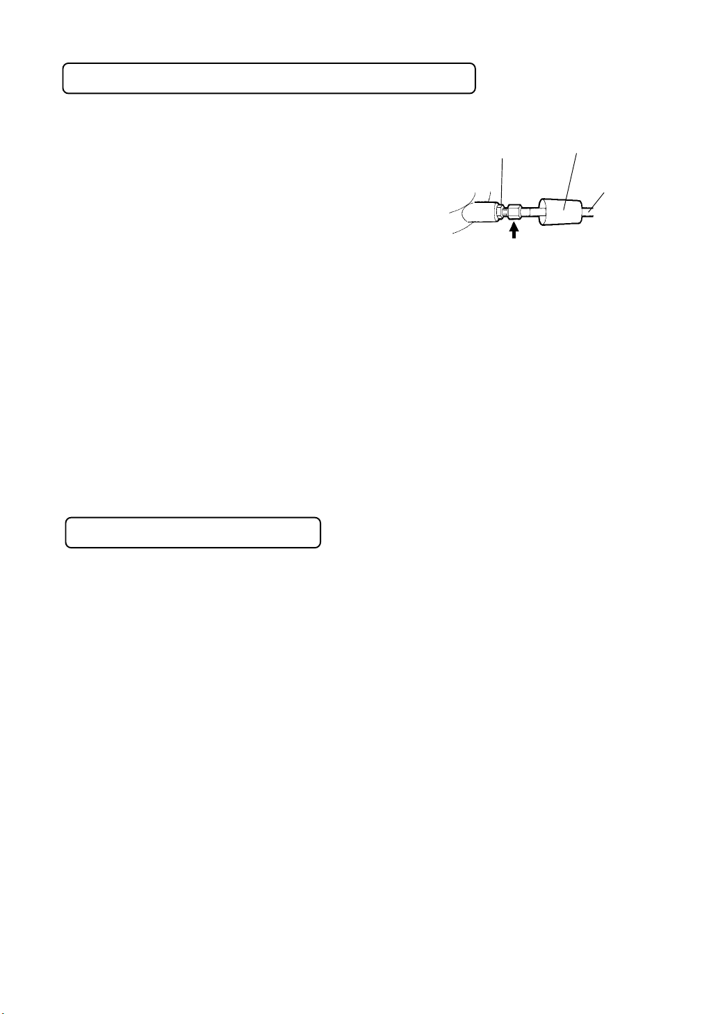
Remove the plastic cap located on the bottom of the cable.
(see Fig. E)
3.3.
3.
3.3.
Hold the adjusting screw with your right hand and push it towards the direction of the outer cable, then adjust the nut with
your left hand to make the wire tension properly.
FOR MORE INFORMATION
Nut Plastic Cap
Cable
Wire Tension
Adjusting Screw
(Fig. D)
MINOURA JAPAN HEAD OFFICEMINOURA JAPAN HEAD OFFICE
MINOURA JAPAN HEAD OFFICE
MINOURA JAPAN HEAD OFFICEMINOURA JAPAN HEAD OFFICE
1197-1 Godo, Anpachi, Gifu 503-2305 JAPAN
Phone +81- (0)584-27-3131 / Fax +81- (0)584-27-7505
E-mail: minoura@minoura.jp
http:// www.minoura.jp
MINOURA NORTH AMERICAN CENTERMINOURA NORTH AMERICAN CENTER
MINOURA NORTH AMERICAN CENTER
MINOURA NORTH AMERICAN CENTERMINOURA NORTH AMERICAN CENTER
FOR RESEARCH, DEVELOPMENT & MARKETINGFOR RESEARCH, DEVELOPMENT & MARKETING
FOR RESEARCH, DEVELOPMENT & MARKETING
FOR RESEARCH, DEVELOPMENT & MARKETINGFOR RESEARCH, DEVELOPMENT & MARKETING
1996 East Avenue, Hayward, CA 94541-5454 U.S.A.
Phone 510-538-8599 / Fax 510-538-5899
E-mail : MinouraUSA@ATTglobal.net
Made & Quality Controlled in Japan
Copyright © 2002 Minoura Japan, All Rights Reserved.
 Loading...