

Page 1

M60-D
Indoor Bicycle Trainer – instructions manual
Tire Size Capacity Range <with Z-Adaptor> 26x1.00 - 29x2.10
<w/o Z-Adaptor> 20x1-3/8 - 700x32c
Read this instructions carefully before use
Minoura Japan Headquarters Minoura North American Tech Center
(for all customers) (for U.S. residents only)
1197-1 Godo, Anpachi, Gifu 503-2305 Japan 1996 East Avenue, Hayward, CA 94541 U.S.A.
Phone: +81-584-27-3131 / Fax: +81-584-27-7505 Phone: 1-510-538-8599 / Fax: 1-510-538-5899
Email: minoura@minoura.jp Email: support@minourausa.com
www.minoura.jp
Made in Japan
(ver.1.1 2010/2)
Page 2

IMPORTANT NOTICE
• For use with a normal 2-wheel bicycle only. Do not use a tandem, recumbent, or other.
• Hub nut type rear wheel axle is not compatible with M60-D in standard.
You need to replace the left side coupling (UF-8) with optional "Left Side Coupling for
Hub Nut Axle".
• Fits tire size between 20x1-3/8" and 29x2.10". To use 26x1.00" or smaller tire, install
the optional Small Wheel Adaptor.
• Some assembly required. Use correct tools (10mm spanner & M4 hex wrench).
Tools are not supplied in the kit.
• Use the supplied rear quick release skewer for maximum stability.
Minoura is not responsible for any problem caused from using your own skewer.
• Use on at and level oor or ground for your safety.
• Adjust the roller pressure to the rear tire properly in order to maximize your tire life.
Tire and roller contact will eventually wear both your tire and the trainer roller.
• Adjusting the resistance must be done with the bike stopped. Do not operate the
adjustment lever (EM-13) while the rear wheel is spinning.
• Touching the spinning wheel and/or any other moving parts while training may cause
serious injury. Keep children and pets away from the trainer when in use.
• It is not possible to convert the non-remote resistance unit to the remote control
version one due to a difference in the inside mechanism.
• If you feel any strange noise or smell, stop using M60-D immediately and contact the
retailer where you purchased the M60-D.
• Any warranty will be void if you use M60-D for other purpose than instructed.
Minorua offers 1-year limited warranty on the resistance unit and 5-year limited
warranty on the frame from the date of your purchase for any problem caused by
manufacturer's defect.
Any damage or problem caused by transporting process is not covered under warranty.
Any damage from shipping or moving must be made to the shipping company.
Read enclosed "Minoura Limited Warranty Policy" card for more detail.
- Page 2 -
Page 3
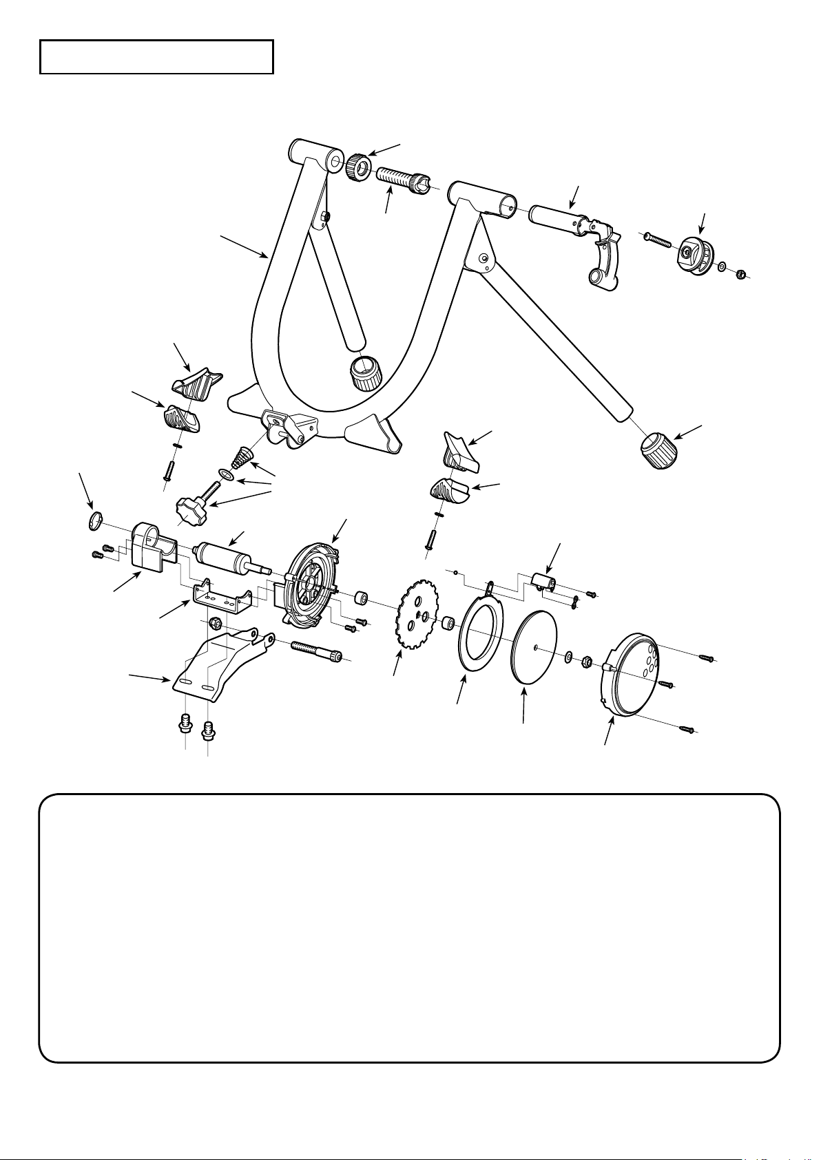
M60-D Schematics
BF-2
BF-5
BF-6
UF-18
UF-17
UF-7
UF-8
EM-1
MF-3
EM-3
EM-2
EM-11
LM-10
EM-4
EM-5
EM-16
BF-2: M60 Main Frame (Blue) EM-1: Outer Cap
BF-5
BF-6
EM-17
M5-2
EM-13
EM-18
BF-5: Leg Rubber Cover (White) EM-2: Axle Holder
BF-6: Leg Rubber EM-3: Drive Roller & Bearing
UF-7: Clamp Lever Guide EM-4: Main Housing
UF-8: Left Side Coupling (for Q/R skewer) EM-5: Alloy Rotor
UF-17: Right Side Coupling & Clamp Lever EM-11: Connecting Plate
UF-18: Coupling Lock Ring (White) EM-13: Resistance Adjust Lever
M5-2: Rubber Foot Cap (29mm) EM-16: Magnet Plate (for M60-D)
MF-3: Roller Pressure Adjust Knob EM-17: Flywheel Disc (0.6 kgs)
LM-10: Base Plate EM-18: Flywheel Cover (White for M60)
- Page 3 -
Page 4

How To Setup Your M60-D Trainer
!
!
!
!
Replace your rear wheel quick release skewer to the supplied one.
1.
Minoura guarantees the stability only when using the supplied skewer due to the coupling inner shape.
If your bike is not equipped with quick release skewer and it's a hub nut type,
replace the left side coupling (UF-8) to the optional "Left Side Coupling for Hub
Nut Axle".
Minoura doesn't guarantee the stability if you don't replace the left side coupling.
You don't need the supplied quick release skewer if your wheel is a hub nut type.
It's not possible to convert your wheel from the hub nut type to the quick release
skewer type unless replacing the hub.
Install the Mag unit and the Roller Pressure Adjust
2.
Knob set (MF-3) to M60-D. (see Fig. A)
Required Tools: 1 x 10mm Spanner
1 x M4 Hex Wrench
Remove the pre-installed bolt from Base Plate
(LM-10).
Attach Mag unit to the bracket on frame, align the
holes, and put through the bolt.
Tighten the bolt with 10mm spanner and M4 hex
wrench.
Do not overtighten the bolt,
otherwise the Mag unit will
not move smoothly even if
you rotate the knob.
If properly installed,` the
Mag unit will come down
slowly with its own weight
when you release it.
Install the knob set to the welded nut on the bracket.
(Fig. A)
Make sure the acorn shaped spring
direction is as shown in Fig. A.
Failure will cause difculty on rotating.
Fully open both legs and place M60-D on a at
3.
and level oor. (see Fig. B)
At this moment, make sure all 4 foot are
contacting the oor at once to sit on the oor
stable.
- Page 4 -
(Fig. B)
Page 5
!
!
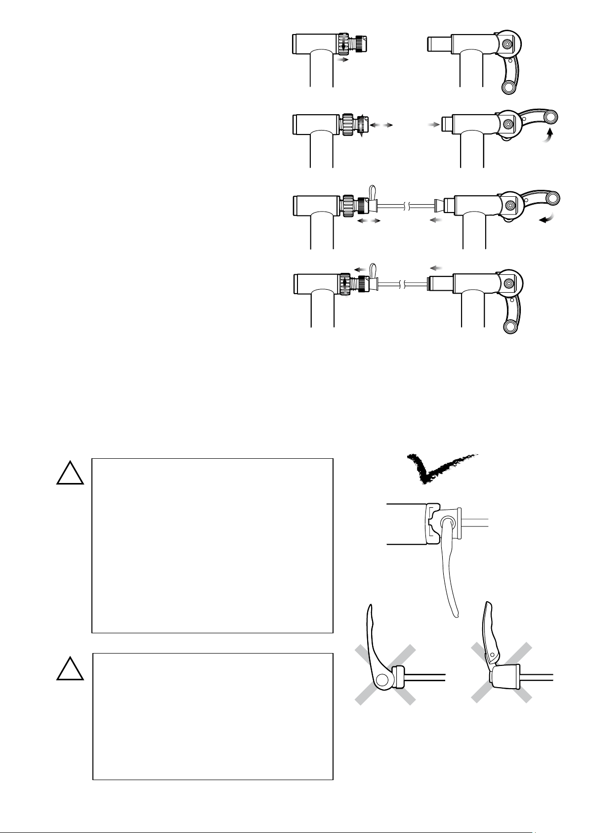
Place your rear wheel in between the couplings.
4.
Loosen the lock ring (UF-18) to allow the
1)
left side coupling (UF-8) be free. (see Fig. C)
Pull up the quick hub clamp lever (UF-17)
2)
to retract the right side coupling. (see Fig. D)
(Fig. C)
Insert the left side (quick lever side) skewer
3)
into the left side coupling rst.
The quick lever shaft must be inserted into the
cut-out on the coupling to hold the bike stable.
Turn the coupling to adjust the cut-out position.
While keeping this position, slowly come
4)
down the bike to align the right side acorn nut
to the right side coupling.
Push down the quick hub clamp lever to hold the rear wheel. (see Fig. E)
5)
If you start feeling resistance when the lever comes at 4 o'clock position, it's correct.
If the clamping hub is too tight or too loose due to wrong position of the left side coupling, pull up the
lever to release the bike, adjust the left side coupling position and try clamping the hub again.
Lastly, tighten the lock ring to x the left side coupling position. (see Fig. F)
6)
(Fig. D)
(Fig. E)
(Fig. F)
Both left and right side couplings are
designed to suit the supplied quick release
skewer. The left side coupling must t
perfectly in the skewer head to get correct
stability. (see Fig. G)
Any skewer type which lever is located on
the end of the axle (Fig. H) or the lever will
not be bent over right angle (Fig. I) cannot
be used on M60-D.
Precisely adjust the left side coupling
position to keep the correct thightness of
rear hub clamping.
Too tight setting will cause damage to both
M60-D and your bike frame.
Too loose setting may cause the bike to
(Fig. H)
(Fig. G)
(Fig. I)
come out of the trainer during use.
- Page 5 -
Page 6

!
Contact the Drive Roller to the rear tire by turning the Roller Pressure Adjust Knob clockwise. (see Fig. J)
5.
The best position is that the roller compresses the tire in the depth of 3 - 4 mm. (see Fig. K)
Please note too much and too less roller pressure will bring premature tire wear.
Keep correct roller pressure and maintain the air pressure in correct level before
using M60-D.
TIPS
The rear tire should sit in the almost center part of
6.
the Drive Roller without touching any other parts.
(see Fig. L)
If the tire has touched the plastic parts (Fig. M)
due to some reasons like the rear wheel is not trued
If it's hard to tighten the knob bolt, lift up the Mag unit by hand then tighten the knob.
(Fig. J)
(Fig. K)
correctly or you have installed a too fat tire, you must
adjust the Mag unit position.
To do so, loosen the backside screws with M5 hex
wrench, adjust the roller position, then tighten the
screws again tightly. (see Fig. N)
(Fig. L)
(Fig. N)(Fig. M)
- Page 6 -
Page 7

!
If the rear tire has touched any other parts than the Drive Roller, the part may be
!
damaged and your tire will wear out quickly.
It is impossible to adjust the rear wheel position by adjusting the left side coupling
position. It just works to adjust the coupling distance.
To remove the bike from M60-D, loosen the knob then lift up om the clamp.
5.
If you remove the bike without changing the roller position, the next installation may become difcult
because the rear wheel has been pushed forward by the roller.
How To Adjust Resistance Level
M60-D provides 3 different resistance levels to suit your
training level.
To Increase Resistance Level:
Slide the Dial Lever toward "H" position.
To Decrease Resistance Level:
Slide the Dial Lever toward "L" position.
How To Use Small Wheel Adaptor (option)
If you wish to use the tire sized 26x1.0" or smaller,
you need to install the optional Z-shaped "Small
Wheel Adapter" between Base Plate and Mag unit to
raise up the roller height.
The direction of Z-adapter is xed so follow the
arrow printed on the top and make sure it's pointing
Required Tools: 1 x 10mm Spanner
1 x M5 Hex Wrench
Z-Adaptor
Hex Head Bolt
toward the front (toward your bike).
If the drive roller cannot reach the tire even if you
install the adaptor, make sure you have been installed
in correct direction.
Use the original cap head bolts for Base Plate, and
use the supplied hex head bolts for the Mag unit.
Cap Head Bolt
(in case of GYRO V270)
- Page 7 -
 Loading...