

Page 1
Warranty Period : 1 year
LiveRide
Applicable Tire Size Capacity:
any 24-inch – 700 x 40c
(Max Tire Outer Diameter = 712mm)
LR960
instructions manual
(ETRTO 42-622)
(ver.1.1 2013/8)
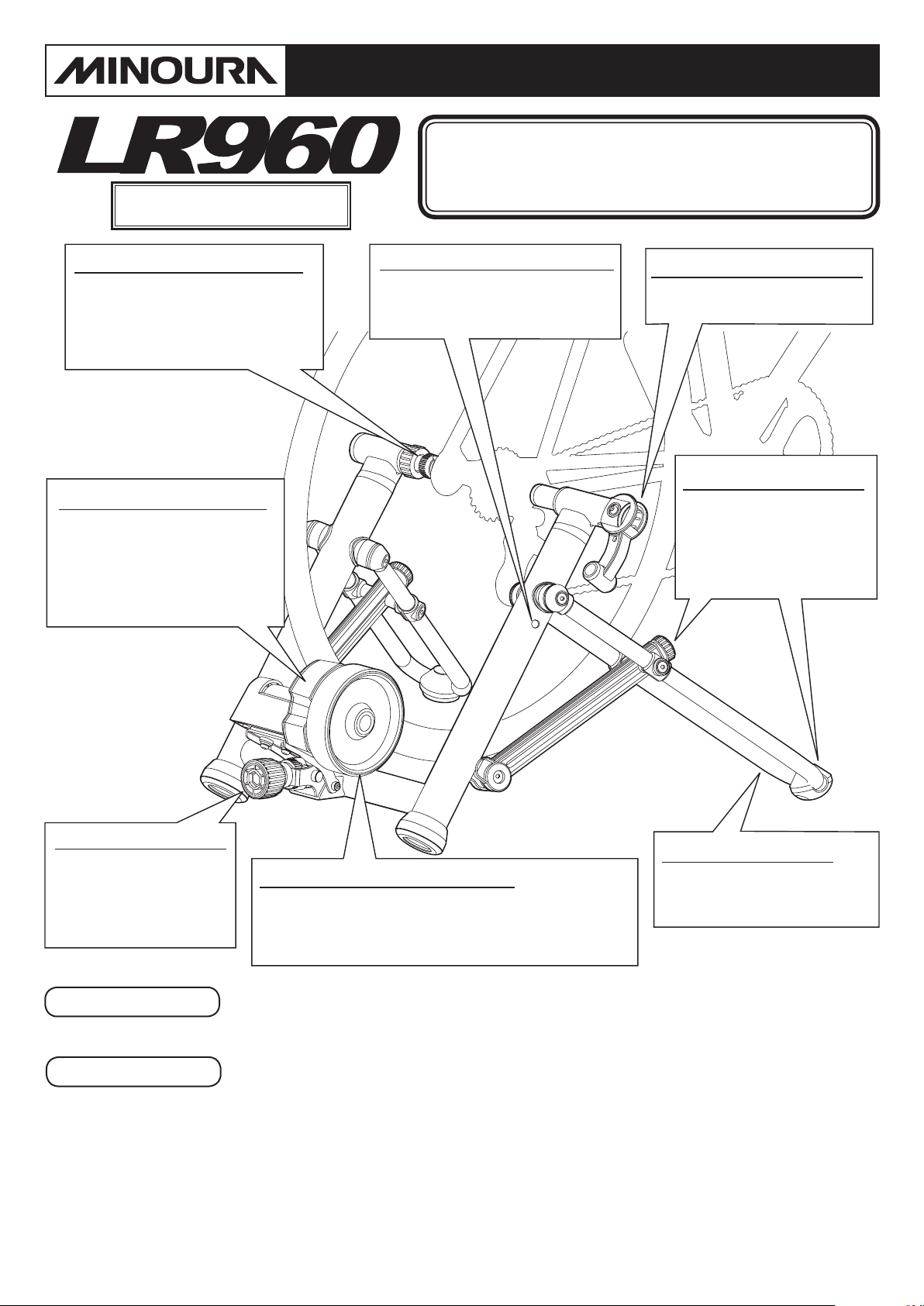
Bolt Type Left Side Coupling
Fits 120 – 145 mm standard hub
width. For quick release type hub
only. For xed nut hub, replace
to the optional "Longer Left Side
Coupling Bolt" (SKU:400-1285-00).
Tandem Magnet Type Unit
A world's rst. Primary magnet
is engaged for the rst 7 levels
then the second magnet kicks in
for the next 6 levels.
Gives you the widest range of
resistance of any trainer.
U-Leg Hole for Smaller Wheel
Use this hole for all 24", 26", and
650c wheels to keep the bike
horizontal.
Quick Release Hub Clamp
Mounts/dismounts your bike in
seconds.
Micro-Adjustable Legs
By turning the dial, the legs
can be adjusted +/- 10 mm
to accommodate uneven
surfaces for complete
trainer stability.
Roller Pressure Knob
Double-threaded system
enables quick and easy
operation to engage/
release the roller to/from
the rear tire.
Please Note
Contact
Lighter Flywheel = More Power
Our patented ywheel weighs less for greater
portability but performs as well as a ywheel weighing
35% more. The key is the inside stair-step design for
perfect power transmission when you need it.
This trainer must be used with a completely smooth (no knobs or raised tread) tire.
Failure to do so will ruin the mag unit, your tire, and void any possible warranty.
If you need help, please contact the shop first where you originally purchased this product
or call the distributors in your country. The distributors list can be found on our web site.
When you cannot get enough service, you can contact us;
Tubular U-shape Leg
Not just for unique design, but
reduces weight and provides
great stability.
MINOURA NORTH AMERICA MINOURA JAPAN HEADQUARTERS
(for U.S. residents ONLY)
Phone: 1-510-538-8599 (8 am - 5 pm, Mon - Fri, PST) 1197-1 Godo, Anpachi, Gifu 503-2305 Japan
Fax: 1-510-538-5899 Phone: +81-584-27-3131
Email: support@minourausa.com Fax: +81-584-27-7505
Email: minoura@minoura.jp
Web: www.minoura.jp
(for ALL customers)
Made in Japan
Page 2
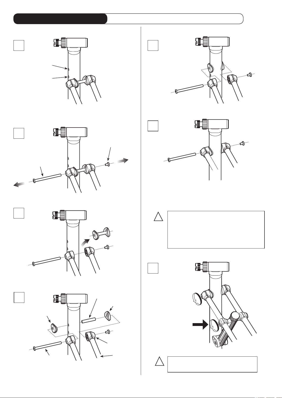
How To Assemble U-Leg
Required Tools: 2 x 5mm Hex Wrench (supplied)
1
for 700C
for 22"~26"
Choose the pivot hole of the U-Leg for your
bike size on the main pillar.
2
Pivot Bolt
(Nut Side)
650C
Pivot Bolt
(Screw Side)
(Fig. A)
5
(Fig. E)
Attach the U-Leg to the main pillar.
6
(Fig. F)
Disassemble the pivot bolt.
3
Remove the alloy sleeve and plastic washers.
4
Plastic Washer
Alloy Sleeve
Plastic Washer
(Fig. B)
(Fig. C)
End Plug
Check that the plastic end plugs on the U-Leg are
fully inserted and lined up with the hole.
Then insert the pivot bolt and fully tighten the
screw with using the supplied M5 hex wrenches.
!
Be sure you fully insert the plastic
end plugs to the U-Leg before
putting the pivot bolt through them.
Failure to do so may cause the legs
to be positioned at different heights.
7
The center
guide bolt is
intentionally
left loose when
packaged at the
factory.
Tighten it slightly
and check to
see that each leg
moves smoothly.
(Fig. G)
Pivot Bolt
U-Leg
(Fig. D)
Insert the alloy sleeve into the selected hole,
and put the plastic washers on both sides.
- 2 -
You do not need to disassemble
!
the center guide bolt. Just tighten.
Page 3
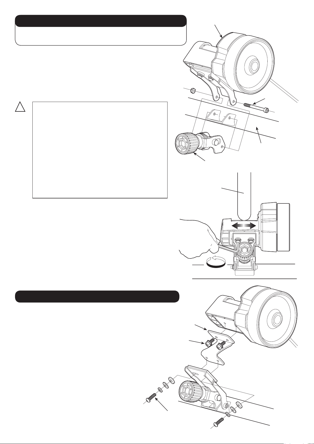
How To Install Mag Unit & Knob Set
Required Tools: 1 x 5mm Hex Wrench (supplied)
1 x 10mm Spanner (not supplied)
The Mag resistance unit and Roller Pressure Knob now
need to be installed to the frame.
First, attach the Knob onto the bracket on the Step-Bar.
Then place the Mag unit over the Knob, and tighten both
brackets together using the pivot bolt and M6 nut. (Fig. H)
Mag Resistance Unit
Pivot Bolt
!
Overtightening the pivot bolt will cause the
Knob to become inoperable.
Make sure you unscrew (loosen) the pivot
bolt by 1/4 - 1/2 turn once you completely
tightened it.
The Mag unit should be lowered towards the
ground by its own weight at this point.
If the pivot bolt is too loose, the Mag unit may
drop suddenly and come down on your hand
or ngers.
Make sure to adjust the torque properly to
insure proper operation.
Your bicycle tire should be as close to the center of the
roller as possible. (see Fig. I)
If the tire has been touching the plastic housing, damage
will occur to the Mag unit and your tire.
The base bracket has two sets of thread holes for mounting
the Mag unit. Choose the better holes.
Also it can be micro-adjusted and to do so, loosen the
backside screws and slide the Mag unit in the direction
needed to center the tire properly.
Tighten the screws when you have finished.
Roller Pressure Knob
Rear Tire
Step-Bar
(Fig. H)
(Fig. I)
How To Use Small Wheel Adaptor
If your tires are 26" or smaller and are less
than 1.75" in width, you will need to use the
supplied Z-shaped Small Wheel Adapter.
Your tire size should be clearly marked on the
tires sidewall.
The direction of the Z-adapter is fixed so
follow the arrow printed on the top and make
sure it's pointing toward the front (toward
your bike).
If the drive roller cannot reach the tire, make
sure the Z-adapter has been installed correctly.
Use the original round head bolts for the
Mount Base, and use the supplied hex head
bolts for the Mag unit. (see Fig. J)
Z-Adaptor
Hex Head Bolt
Round Head Bolt
- 3 -
(Fig. J)
Page 4

Placing LR960 on Floor
Fully open the legs and place on a flat and horizontal floor.
!
To open the U-Leg, grab the main frame and the rubber cap on the U-Leg (see Fig. L).
Do NOT pull the Alloy Leg Guide directly, otherwise it may be bent or damaged.
Main Frame
Alloy Leg Guide
U-Leg
(Fig. L)
(Fig. K)
Adjuster Knob
Check that all 4 points are touching the floor
evenly. (see Fig. M)
If all 4 points are not touching the floor
evenly, the frame could be deformed and
cause damage to the trainer and possibly
your bike.
About Leg Height Adjuster
Each U-Leg height can be adjusted individually by
+/- 10 mm travel.
This adjuster allows for uneven floor or ground
compensation to help insure proper stability.
UP
DOWN
(Fig. M)
When using the adjuster, be sure to check and
make sure that all 4 points are touching the ground
evenly.
And the trainer should be positioned as close as
possible to the floor for better stability.
- 4 -
(Fig. N)
Page 5

How To Mount Your Bike
LR960's coupling position is pre-adjusted in the factory to fit the 125mm standard rear hub width.
If it is too loose or too tight to your bike, or if you use different width of rear hub like a track race
bike, adjust the left side coupling as precisely as possible for maximum stability.
Please note there is no adjustment on the right side (lever side) coupling.
Applicable Hub Width: 120 – 145mm
!
!
1
2
3
The coupling cone shape is designed to t the supplied quick release skewer perfectly.
We strongly recommend you to replace your rear wheel skewer with the supplied one.
We do NOT guarantee the stability while using LR960 with your own skewer.
If your bike's rear hub axle is NOT a quick release skewer type, but a hub nut type, you
don't need to use the supplied skewer.
The standard left side coupling bolt (UF-8) is too short to hold the hub nut type axle.
You must replace it to the optional longer one "Extended Left Side Coupling Bolt for Nut
Type Hub (SKU: 400-1285-00)" for your safety.
The following steps describe the micro adjustment of the left side coupling. This step is not always required
and once fixed in the proper position, you should not need to adjust again. Once adjusted to fit your bike,
simply operate the Quick Hub Handle Lever for a proper fit every time.
First, loosen the red Lock Ring by
turning it counter-clockwise.
The left side coupling is actually a bolt/
coupling combination.
Turn the coupling to adjust the position.
Raise the Quick Hub Clamp Lever up
to retract the right side coupling.
Lock Ring
Left Side Coupling
Right Side Coupling
Quick Hub
Clamp Lever
(Fig. O)
Insert the left side hub end (quick release
4
lever side) into the left side coupling cone.
In this position, place the other side of
5
the bike into the right side (rear cog side)
coupling cone. Make sure your derailleur
cable goes OVER the coupling.
Now, push down (lower) the Quick
6
Hub Clamp Lever until it fully engages
the skewer or axle nut.
Make sure the Quick Clamp Hub Lever
7
is lowered into its locked position and
cannot be lowered any further.
The frame may appear slightly open
but this is normal.
If the frame seems to be opened too
widely, re-mount your bike following
the instructions. Failure to do so could
damage your bike and/or the trainer.
Now, grab the saddle of your bike and rock the bike back and forth to make sure your bike is
8
securely in the trainer. Your bike should not move independently of the trainer where it is attached.
Quick Release Skewer
(Fig. P)
(Fig. Q)
(Fig. R)
Tighten the red Lock Ring firmly to fix the left side coupling position.
9
- 5 -
Page 6

Roller Pressure Adjustment
Fully turn the red knob counter-clockwise. (initial position)
1
Turn the silver dial counter-clockwise until the drive roller touches the tire surface.
2
Turn the red knob clockwise to compress the tire by the roller. (required depth = 3 – 4 mm)
3
(Fig. S) (Fig. T)
Turn the silver dial counter-clockwise Turn the red knob clockwise
Tire wearing must occur on any tire drive system. To minimize the tire wear and maintain the tire
life as long as possible, it's crucial that you precisely adjust the roller pressure against the tire.
Too much contact with the roller may deform the tire and cause premature tire wear or burst.
Too little contact will cause the tire to slip on the roller when you pedal and build up excessive heat
that may cause your tire to melt.
The correct pressure is the roller compresses the tire in the depth of 3 – 4 mm.
To remove the bike, loosen the red knob only.
4
same tire.)
もしダイヤルやノブが固くて回せないときは、赤い
!
ノブを手前に引っ張り(内蔵バネの力で戻ろうとし
ます)中心のボルト孔に指を挿入して保持してやる
ことで、意図的にダイヤルやノブをフリーにするこ
とができます。この状態で操作してみてください。
(You don't need to loose the silver dial whenever using
タイヤの空気圧が低いと「キュルキュル」という異
!
音が発生し、またタイヤの摩耗が早まります。
トレーナーで使用する際はタイヤの空気圧は通常よ
りも 1 割ほど上げるようにしてください。
またタイヤ表面の汚れは除去しておいてください。
- 6 -
(Fig. U)
緩めるのは赤いノブだけ
Page 7

How To Operate Remote Shifter
LR960 comes with a convenient remote shifter device.
By installing it on your handlebar or stem, you can adjust the
resistance level in 13 levels without getting off the bike.
The plastic band is soft enough to fit aero-shaped carbon handlebar
or round shaped stem as well as the standard round dimension
handlebars.
How to install the remote shifter
1) Wind the plastic band around the handlebar
2) Hook the tip to the gutter on the plastic shifter base (Fig. V-1)
3) Flip up the lever to lock (Fig. V-2)
How to increase the resistance level
Twist the shifter dial toward "H" symbol
How to reduce the resistance level
Twist the shifter dial toward "L" symbol
!
"L" is not zero resistance. There is still some resistance
at "L" level due to the roller compression to the tire.
The remote shifter is pre-adjusted to fit the standard handlebar
size; 22mm (7/8") diameter.
If it becomes loose or too tight, or you need to install the shifter
onto an oversized handlebar or stem, adjust the band length by
turning the plastic screw with an M4 hex wrench (see Fig. Y).
2
1
(Fig. V)
(Fig. W)
Decrease
Indicator
(white dot)
!
Do not overtighten the plastic screw. It will break the
plastic band. Release the hook before adjusting.
How To Adjust Remote Cable
If you cannot shift at L or H position, it's time to adjust the cable tension.
1) Set the remote shifter lever at "H" position and straighten the cable.
2) Pull off the black plastic cap on foot of the cable, then the adjusting
screw will appear. (Fig. Z)
3) While pushing the outer cable toward the shifter, push the adjusting
screw to the outer cable. (Fig. Z & AA)
4) Turn the lock nut until it touches the Mag unit. You shouldn't
overtighten the nut, otherwise you won't be able to set the shifter at
"L" position.
5) Insert the plastic cap again.
Adjusting Screw
Lock Nut
(Fig. X)
Increase
You must release the hook
for adjusting screw
(Fig. Y)
Cap
(Fig. Z)
- 7 -
(Fig. AA)
Tighten nut until it touchs housing
Page 8

LR960 Schematics
UF-9
UF-8
TM-1
GM-7
UF-6
UF-7
UF-18
UF-5
UF-2
UF-4
UF-13
UF-3
GM-26
TM-6
TM-2
TM-4
CAUTION
!
Do NOT touch TM-6 "Alloy Rotor" during
and 15 minutes after workout.
It's VERY HOT and may burn you.
UF-2 : U-Leg (Red painted) GM-1 : 2.7kgs Flywheel
UF-3 : Alloy Leg Guide GM-7 : Drive Roller Holder
UF-4 : Height Adjuster Cap GM-26 : Roller Pressure Knob
UF-5 : Height Adjuster Knob TM-1 : Remote Shifter (Twin)
UF-6 : Right Side Coupling & Clamp Lever (Red) TM-2 : Drive Roller
UF-7 : Clamp Lever Guide TM-4 : Main Housing
UF-8 : Left Side Coupling TM-6 : Alloy Rotor
UF-9 : Coupling Lock Ring (Red)
UF-13 : Ruber Cap
UF-18 : Main Frame
GM-1
Other Languages / Andere Sprachen / Autres Langues / Otros Idiomas
If you need the instructions manual written in different language(s) such as
GB
German, French or Spanish, check out the following web page.
Wenn Sie deutsches Versionsanweisungen-Handbuch brauchen, überprüfen Sie die
G
folgende Webseite bitte.
Pour télécharger les instructions en français, veuillez vous rendre sur la page Web
F
dont l'adresse figure ci-bas.
Si necesita el manual de instrucciones de versión español, compruebe la página web
ES
siguiente.
 Loading...