

Page 1
MINOURA HyperRim Instruction Manual
Please read this instructions carefully before use.
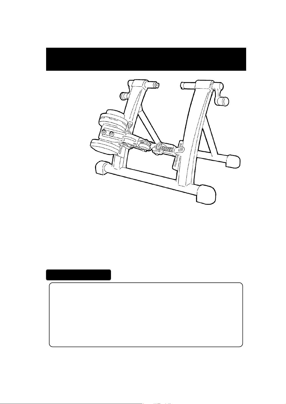
(This figure is
HyperRim type-D)
Thank you for
purchasing
Minoura's HyperRim
Trainer with RDA and our patented Hyper
Magturbo.
With its unique rim-drive system, the HyperRim is our most sophisticated bicycle home trainer for both road and mountain bikes. Minoura has long
been an innovator in stationary trainers, and our new HyperRim trainer continues that tradition. The
Rim Drive Action (RDA) system has special drive pulleys that contact only the rim, avoiding wear and
tear to the tire and any unpleasant noise. With the RDA system, training is smoother, more controlable,
and quieter. Plus, you avoid the cost of replacing worn-down tires. The RDA system can handle
almost any bicycle with a wheel diameter of 26 to 28 inches and is the best trainer yet for mountain
bikes.
IMPORTANT NOTES
• Read all instructions carefully before use.
• Some assembly required.
• Keep the manual handy at all times. Lost instruction materials can be replaced
through Minoura or your local dealer.
• Do NOT use trainer for any other purpose than instructed.
• The trainer is manufactured to precise standards. You may not disassemble or
rebuild it.
• "HyperRim" and "RDA" are trademarks of Minoura and may not be copied.
- 1 -
Page 2
WARNING
Use two-wheeled bicycles only. Tandems may be used if balanced correctly.
!
Remove all oils and moisture from drive pulleys before use.
!
Keep both hands on handlebars at all times and maintain a normal riding position.
!
After you ride bicycle on the HyperRim trainer, remove all dirt and particles from rim,
!
so that you'll have effective braking on your future rides.
Please obey warning signs.
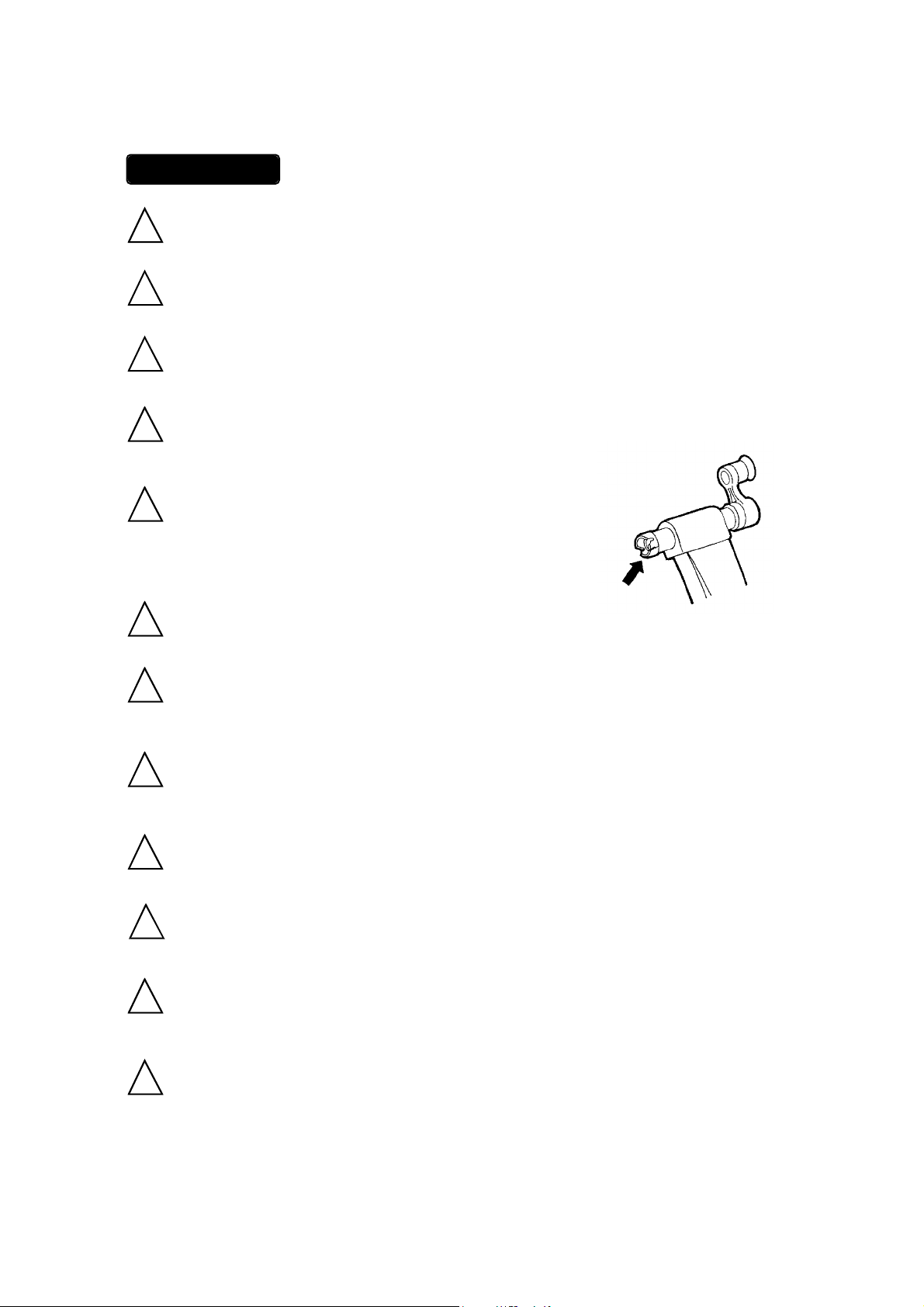
Check the couplings supporting the rear hub for damage
!
and cracks. Accidents may occur from cracked or damaged
couplings.
When using the HyperRim trainer, place it on a flat surface for safe training.
!
Adjust the drive-pulley height so they are even and touching the bicycle rim only (not
!
the tire).
Do not over tighten the hub-clamp handles. Over-tightening may cause damage to
!
the trainer or bicycle frame. The clamp handles should be a snug and secure fit. Do
not force!
Keep away from small children.
!
Before use, make sure all bolts and nuts are securely fastened.
!
X
When installing your bicycle, make sure the rim is located in the center of the frame.
!
This centering can be achieved by rotating the hub-clamp handles.
Keep hands and feet away from spinning rollers and wheels at all times.
!
- 2 -
Page 3
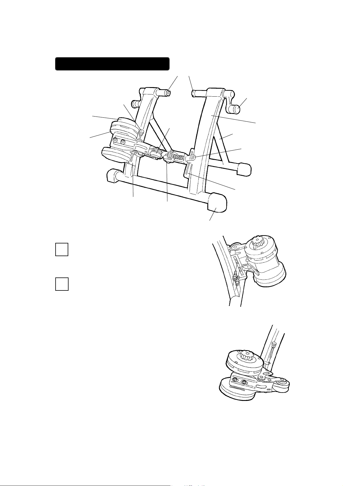
ASSEMBLING YOUR TRAINER
Couplings
Mag Unit Height
Adjust Knob
Load Adjust
Dial
Mag Unit
Mag Unit
(This figure is type-D)
Open the frame and U-Leg and place on level floor.
1
Installation
Slot
Drive Roller
Assistant Roller
Hub-clamp Handle
Frame
U-Leg
Drive-pulley
Lever
Assistant Roller
Unit Installation
Slot
(Fig. A)
Rubber Foot Cap
Prior to assembly of the Mag Unit, locate the two
2
bolts and two washers. Find the left-side slot on the
trainer. While placing the Mag Unit at the recommended position on the inside of the slot, attach it
with the bolts and washers by using the included hex
wrench.
(see Fig. B)
After installing the Mag Unit, put the Height Adjust
Knob (this is optional) through the hole on the left
side slot, and then tighten it to the thread on the Mag
Unit’s support base. This optional Height Adjust
Knob will help you adjust the height of the Mag Unit
so that the rubber roller will fit properly on the rims
side wall. (see Fig.C)
(Fig. B)
(Fig. C)
- 3 -
Page 4
Mag unit must be assembled on the left side
!
of HyperRimTrainer and the Assistant Roller
Unit on the right. Follow directions EXACTLY. See diagram for accurate placement. After deciding the height of the
pulleys tighten handle securely to avoid
damage to equipment and/or rider.
(see Fig. D)
Handle with care! Damage may occur if Mag unit is dropped.
!
Install the Assistant Roller unit to the right side of the frame, using
3
the same process as with the left-side Mag unit. Make sure the
assembly is secure and accurate. (see Fig. E)
Notes
The HyperRim is foldable and portable without requiring
disassembly of the Mag unit and assistant roller unit.
(Fig. D)
The Mag unit must be on the left side of the HyperRim’s frame,
!
and the assistant roller unit must be on the right side.
Both drive pulleys must be adjusted so as not to touch the tire.
You do not need to set this adjustment at this stage of the assembly --- you can adjust it later, before use. Once you have set the
height of the pulleys, you must tighten the bolts firmly. If they are
loose, the assembly may break and/or damage your bicycle.
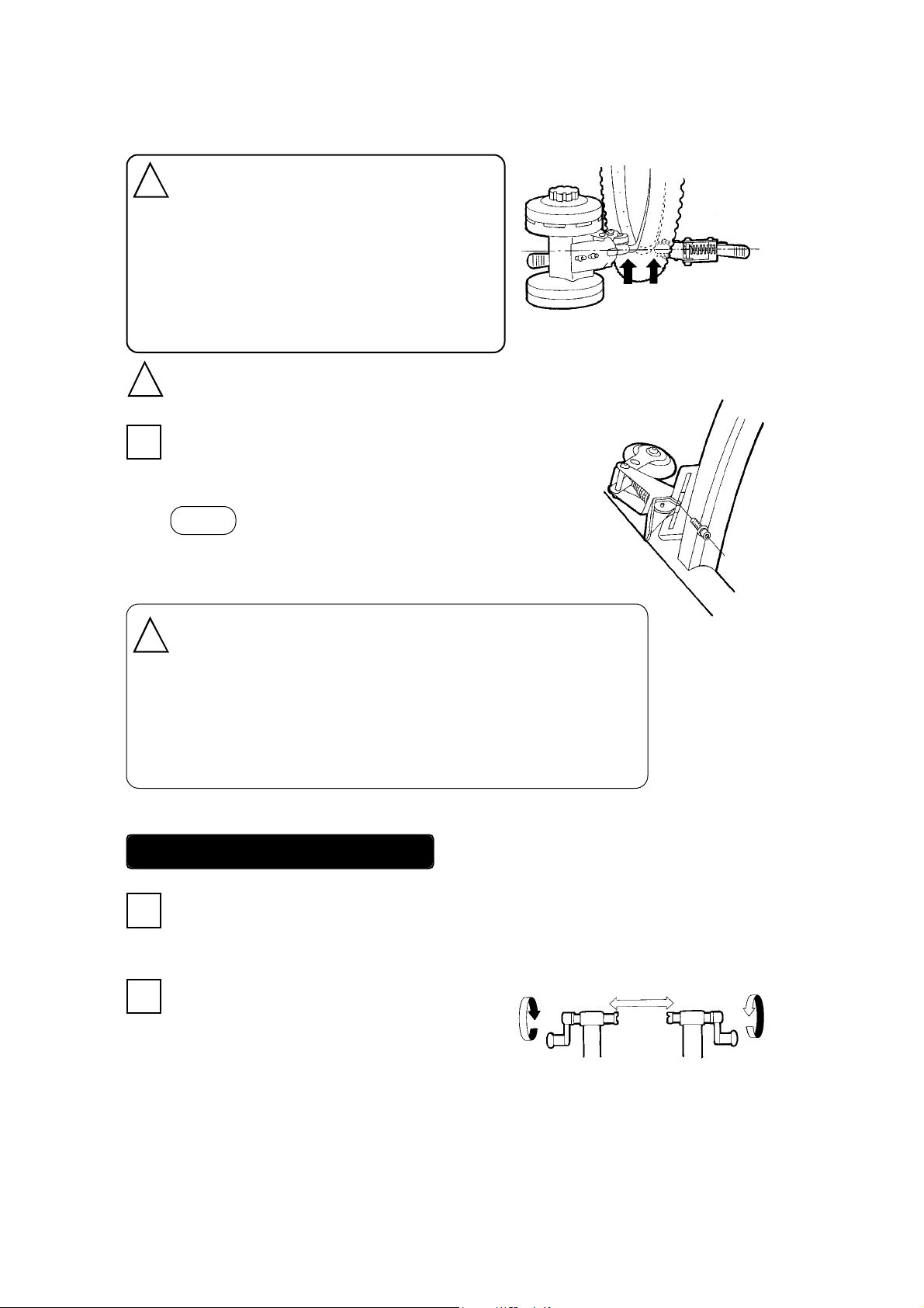
INSTALLING YOUR BICYCLE
Before installing your bicycle, rotate both hub-clamp handles counter-clockwise to create a wide
1
clearance between the couplings. (see Fig. F)
Place the bicycle's rear hub between the two
2
couplings, making sure that the quick-release
skewer (or hub nut) is not yet touching either
couplings. Then rotate the hub-clamp handles
clockwise to fix the rear hub. Tighten until securely
fastened, but do not overtighten.
(Fig. E)
(Fig. F)
- 4 -
Page 5

Notes
3
Once you have set the correct position of the rim for your bicycle, you can install or
remove your bicycle by rotating only one hub-clamp handle. This feature saves
time.
The Left-side coupling has a cut-away section to accomodate the shaft of the quick-
!
release lever. You must align this coupling with the shaft of the QR. Failure to do
so may cause the coupling to improperly support the bicycle.
The couplings are designed to acommodate a certain style of quick-release lever.
!
If you use an incompatible quick-release lever, it may not be properly supported be
the coupling --- so you must change your quick-release to the correct style in order
to prevent accidents.
The white levers control the release and placement of the rollers to the rim. By adjusting these
levers, you will see that the two rollers contact the rim sidewall with equal tension.
If they are not resting on the rim properly, but on the tire, then you must re-adjust the height of
the drive pulleys so that the roller contact is solely on the rim. (see Fig. G)
If the rollers are rubbing against or touching
!
the tire, it may cause the tire to burst.
Roller-to-rim contact ONLY! (see Fig. H)
Be careful not to pinch fingers in springs while adjusting.
!
(see Fig. I)
- 5 -
(Fig. G)
(Fig. H)
(Fig. I)
Page 6

To remove your bicycle from the trainer:
4
First, push down both white levers (see Fig. J). This
releases the rollers and drive pulleys from the bicycle rim.
Then rotate the hub-clamp counter-clockwise until loose,
and pull out the bicycle.
(Fig. J)
USING THE MAG UNIT
The Mag Unit has seven different levels of load force, replicating actual riding resistance.
The load settings range from high (H) to low (L) and can be adjusted via the orange dial on the Mag
Unit. The rider may also adjust the load force by shifting up or down among his gears, depending on
the level desired.
We recommend that you start with a medium to low load force and gradually work up, increasing force
as muscled warm up.
Increasing Load Force
To increase the load force, turn the orange dial on the Mag unit toward
the “H” symbol. (see Fig. K)
When your Mag unit is a remote control type, twist the lever on your
handlebar toward the “H” symbol.
Decreasing Load Force
To decrease the load force, turn the orange dial on the Mag unit
toward the “L” symbol. (see Fig. L)
The lowest selection is not zero load; there still be a small level
of force.
When your Mag unit is a remote control type, twist the lever on
your handlebar toward the “L” symbol.
H
(Fig. K)
L
(Fig. L)
L
- 6 -
H
Page 7

REPLACING YOUR DRIVE ROLLERS
When you first start riding, the HyperRim’s rubber rollers may be stiff and cause the rim to slip. But
the rollers will soften after a few rotations and will impart the proper rim grip. The rubber rollers may
melt or wear from excessive heat over longtime use.
The rim-drive rollers will eventually wear and need to be replaced. When you find that your load force
has diminished significantly or that you feel some vibration that cannot be fixed through minor adjustments, then it is time to invest in a “roller replacement set”. This set is available from your Minoura
dealer.
Directions
To remove: Apply a 10mm wrench to the nut behind the pulley while
1
turning the bolt with a M4 hex wrench.
(see Fig. M)
If you are changing the roller on the Mag unit (left) side,
2
go to step 3.
To change the roller on the assistant-roller-unit (right) side, pull back
the pulley and remove the rubber roller.
(Fig. M)
To remove the pulley on the Mag Unit (left) side, you must loosen
3
the two bolts that are located on the surface of the Mag unit with a
M4 hex wrench.
Push the Mag unit in the direction of the drive roller to loosen the
V-Belt and then pull out the pulley.
(see Fig. N)
Do not remove the bolts that control the
!
tension on the V-Belt.
As you did with the right-side roller in step 2, pull out
4
the rubber roller from the pulley.
(see Fig. O)
Be sure to replace both rollers at the same time
!
to prevent uneven wear to the rim and to ensure
a more balanced ride.
- 7 -
Drive pulley
Rubber roller
Plastic shaft
Under pulley
cover
(Fig. N)
(Fig. O)
Page 8

After replacing the rollers, you must fix the pulley’s upper and lower covers firmly.
5
On the Mag unit side, after applying the pulley you must pull the Mag unit to tension the VBelt.
Then, tighten the two bolts while holding the V-Belt in the proper tension.
When you fix the upper and lower roller covers, you must
!
make sure these covers are parallel.
If the covers are not parallel, it may result in vibration that
may loosen the rollers and cause an accident. (see Fig. P)
(Fig. P)
MAINTENANCE AND SERVICE
• If strange noises or vibration persist, discontinue use immediately and return to your Minoura dealer
or place of purchase for assistance. You may also contact Minoura Co.,Ltd.: 1197-1 Godo, Anpachi,
Gifu 503-2305 Japan, or contact to Minoura North American R&D Center at 1-510-538-8599 or email
to MinouraUSA@ATTglobal.net.
• Always check for tightness of bolts and nuts before using.
• Check V-Belt and couplings for excessive wear or damage.
• Remove all oils and moisture from drive pulleys and other devices.
• Keep dry and out of weather.
NOTE ON DISPOSAL
To dispose of an old or broken trainer, please disassemble as much as possible
!
and recycle properly.
Do NOT dispose of trainer in trash. Harmful gas may occur if burned.
Keep abandoned parts away from children.
- 8 -
Page 9

EFFECTIVE TRAINING INSTRUCTIONS
Effective training requires some load resistance. Even in the minimum load setting, the HyperRim
offers some resistance. A gradual increasing of the load force is better for your muscles and a more
effective form of training.
By manipulating the load force and your bicycle gears, you can get your preferred level of resistance.
We reccomend that you consult a knowledgeable fitness trainer about your personal training program.
Always stretch before riding the trainer, warm up when you begin riding, and cool
!
down slowly when you are finishing your session. This will help to avoid injury to
muscles and joints.
For best results, it is important to maintain a consistent cadence through any
!
changes in load force.
WORKOUT SAMPLE
Below is a sample trainer workout for a rider who is using a mountain bike with the HyperRim trainer.
This exact workout may not be suitable for everyone, but you can modify the gear ratio and load
settings to suit your power and preference. If you need further guidance, please ask a professional for a
personal training program.
Front chainring* Rear cog Cadense
WARM UP 15 minutes Middle 28T 90 rpm
10 minutes Middle 24T 90 rpm
10 minutes Middle 21T 90 rpm
TRAINING 10 minutes Middle 18T 90 rpm
10 minutes Middle 16T 90 rpm
10 minutes Middle 14T 90 rpm
COOL DOWN 15 minutes Middle 21T 70 rpm
* You may shift to the outer ring, but the inner ring will not be effective for training.
- 9 -
Page 10

NOTE ON HIGH SPEED TRAINING
With the Minoura magnetic resistance device, you may be able to reach to speeds in excess of 35 MPH
easily because your tire doesn’t contact with the ground, but only the rollers. This speed is not always
possible on the road or trail, but you can do it on this HyperRim trainer with the lowest resistance load
force and high gear ratio. We highly recommend you do not exceed 30 - 35 MPH as it will cause a
problem on the bearings and/or shaft, and greatly reduce the quality of your wirkout.
This magnetic resistance device is designed for usual training under 35 MPH (56 KPH) speed, so you
should keep your training speed under the limit.
If there is any grinding noise or excessive vibration from your magnetic resistance device during your
training, please contact your dealer or Minoura immediately.
- 10 -
Page 11

REPLACEMENT PARTS
You can get the following replacement parts for your HyperRim trainer through your local dealer;
ORDER #400-1240-00
DRIVE ROLLER (MAG UNIT SIDE)
ORDER #400-1241-00
ASSISTANT ROLLER
(TENSION ROLLER SIDE)
ORDER #400-1255-00
35mm DIAMETER RUBBER FOOT CAP
ORDER #400-1243-00
COUPLING UNIT (REAR COG SIDE)
ORDER #400-1244-00
COUPLING UNIT (QUICK-RELEASE SIDE)
ORDER #400-1242-00
TENSION ROLLER LEVER
ORDER #400-1247-00
V-BELT (K-16)
ORDER #400-1246-00
HUB HANDLE
ORDER #400-7101-00
MAG REMOTE CONTROL SHIFTER KIT
- 11 -
Page 12

RESOLUTION
DIAGRAM
FOR MORE INFORMATION ON YOUR MINOURA TRAINER
MINOURA NORTH AMERICAN CENTER FOR RESEARCH, DEVELOPMENT
AND MARKETING
1996 East Avenue, Hayward, CA 94541-5454 U.S.A.
Phone 510-538-8599 / Fax 510-538-5899
E-mail : MinouraUSA@ATTglobal.net
MINOURA TECHNICAL & WARRANTY CENTER
Toll Free Fax 800-601-9592
MINOURA CO., LTD.
1197-1 Godo, Anpachi, Gifu 503-2305 JAPAN
Phone +81 (0)584-27-3131 / Fax +81 (0)584-27-4258
E-mail: minoura@minoura.jp
http://www.minoura.jp
MADE IN JAPAN
- 12 -
 Loading...