

Miele T300 Technical Information

TECHNICAL INFORMATION
T300 Clothes Dryer Series (Condenser)
This document is adapted from existing information that is used internationally and is
provided for general guidance and informational purposes only. Information may contain
omissions and/or additional data for some USA models.
If you have any questions, require clarification or need assistance – contact the Miele
Technical Support Center at: 1-888-529-8790.
© 2007 Miele USA

T300 Series Clothes Dryer (Condenser)
Technical Information
T300 Series Clothes Dryer (Condenser) – Table of Cont ents
1.0 Construction and Design.........................................................................8
1.1 Features ..................................................................................................10
1.2 Dimensions..............................................................................................10
1.3 Weight .....................................................................................................10
1.4 Capacity................................................................................................... 10
1.5 Drum/Volume........................................................................................... 10
1.6 Casing .....................................................................................................10
1.7 Electrical Connection...............................................................................11
1.8 Drive Motor .............................................................................................. 11
1.9 Air Circulation Fan ................................................................................... 11
1.10 Cooling Air Fan........................................................................................11
1.11 Condensate Pump................................................................................... 11
1.11.1 T 368 C ........................................................................................ 11
1.11.2 T 352 C, T 358 C, T 359 C, T 367 C, T 368 C, T 369 C,
T 369 C-2, T 377 C, T 378 C, T 382 C, T 383 C, T 388 C........... 11
1.12 Rear Drainage ......................................................................................... 12
1.12.1 T 352 C, T 358 C, T 359 C, T 367 C, T 369 C, T 369 C-2,
T 377 C, T 378 C, T 382 C, T 383 C, T 388 C............................. 12
1.12.2 T 368 C ........................................................................................ 12
1.13 Condensate Container Drawer ................................................................12
1.14 Condenser Box........................................................................................ 12
1.15 Controls ................................................................................................... 12
1.15.1 T 368 C, T 369 C ......................................................................... 12
1.15.2 T 368 C, T 369 C-2, T 382 C ....................................................... 12
1.15.3 T 377 C, T 378 C, T 388 C ..........................................................13
1.15.4 T 352 C, T 358 C, T 359 C, T 367 C, T 368 C, T 369 C,
T 369 C-2, T 382 C, T 388 C ....................................................... 13
1.15.5 T 377 C, T 378 C ......................................................................... 13
1.16 Buzzer .....................................................................................................13
1.16.1 T 352 C, T 357 C, T 358 C, T 359 C, T 383 C............................. 13
1.17 Drum Lightning ........................................................................................ 13
1.17.1 T 358 C, T 359 C, T 367 C, T 369 C-2, T 378 C, T 382 C,
T 383, T 388 C............................................................................ 13
1.18 Drying Programs...................................................................................... 14
1.18.1 T 368 C, T 369 C, T 377 C, T 378 C, T 388 C............................. 14
1.18.2 T 368 C, T 369 C ......................................................................... 14
1.18.3 T 377 C ........................................................................................ 14
1.18.4 T 378 C, T 388 C ......................................................................... 14
1.18.5 T 352 C, T 358 C, T 359 C, T 367 C, T 368 C, T 369 C-2,
T 382 C, T 383 C ......................................................................... 14
1.19 Consumption Data................................................................................... 15
2

T300 Series Clothes Dryer (Condenser)
Technical Information
T300 Series Clothes Dryer (Condenser) – Table of Contents (cont.)
2.0 Installation..............................................................................................16
2.1 Installation as a Free-Standing Unit ........................................................16
2.2 Installation under a Continuous Worktop................................................. 16
2.2.1 Models with Half Closed Base Plate (Initial Production Models) .16
2.2.2 Models with Fully Closed Base Plate........................................... 16
2.3 Installation as a Washer-Dryer Stack ...................................................... 17
2.4 Draining Condensate to the Rear ............................................................ 17
4.0 Description of Function........................................................................19
4.1 Electronic Residual Moisture Detection Unit EF 102............................... 19
4.2 Electronic Residual Moisture Detection Unit EF 202............................... 20
4.2.1 Level Control................................................................................ 20
5.0 Service and Maintenance ......................................................................21
5.1 Appliance Lid ........................................................................................... 21
5.1.1 Removal....................................................................................... 21
5.2 Front Panel .............................................................................................. 21
5.2.1 Opening the Front Panel.............................................................. 21
5.3 Electrical Components............................................................................. 23
5.3.1 T 368 C, T 369 C ......................................................................... 23
5.3.2 T 368 C (from Machine no. Prefix 11/…) ..................................... 24
5.3.3 T 369 C-2..................................................................................... 25
5.3.4 T 377 C, T 378 C ......................................................................... 26
5.4 Heater Bank............................................................................................. 27
5.4.1 Heater Bank – Removal (Machine Nos. without a Prefix)............ 27
5.4.2 Heater Bank - Removal from (Machine Nos. Prefix 10/…
or 11/…)....................................................................................... 29
5.5 Heater Bank Thermostat .........................................................................29
5.5.1 Replacement................................................................................ 29
5.6 Fan Unit ................................................................................................... 30
5.6.1 Removal (Machine Nos. without Prefix)....................................... 30
5.6.2 Fan Unit with Drum Drive Motor – Removal Machine Nos. with
Prefix 10/… or 11/… .................................................................... 32
5.7 Cooling Fan – Circulation Fan Belt..........................................................34
5.7.1 Replacement................................................................................ 34
5.8 Condensate Pump................................................................................... 35
5.8.1 Replacement................................................................................ 35
5.9 Microswitch.............................................................................................. 35
5.9.1 Replacement................................................................................ 35
5.10 Drum Drive Motor .................................................................................... 36
5.10.1 Removal....................................................................................... 36
5.11 Cooling Fan ............................................................................................. 37
5.11.1 Removal (Machine Nos. without Prefix)...................................... 37
5.11.2 Cooling Fan Removal (Machine Nos. with Prefix 10/ or 11/) ...... 39
3

T300 Series Clothes Dryer (Condenser)
Technical Information
T300 Series Clothes Dryer (Condenser) – Table of Contents (cont.)
5.12 Drum Drive Belt ....................................................................................... 40
5.12.1 Replacement............................................................................... 40
5.13 Drum........................................................................................................42
5.13.1 Removal...................................................................................... 42
5.14 Rear Drum Seal....................................................................................... 44
5.14.1 Replacement............................................................................... 44
5.15 Front Drum Seal ...................................................................................... 44
5.15.1 Replacement............................................................................... 44
5.16 Bearing Shells .........................................................................................44
5.16.1 Replacement............................................................................... 44
5.17 Condenser Box........................................................................................ 45
5.17.1 Removal...................................................................................... 45
5.18 Fill Ring Seal ...........................................................................................46
5.18.1 Replacement............................................................................... 46
5.19 Door Seal................................................................................................. 47
5.19.1 Replacement............................................................................... 47
5.20 Outer Door Panel..................................................................................... 47
5.20.1 Replacement............................................................................... 47
5.21 Electronic Modules .................................................................................. 48
5.21.1 Replacement............................................................................... 48
5.21.2 Electronic Module EF 102........................................................... 48
6.0 Fault Diagnosis ......................................................................................49
6.1 Checking the Sensor Controls T 377 C, T 378 C .................................... 49
6.2 Checking Residual Moisture Stages........................................................ 50
6.2.1 T 368 C, T 369 C with EF 102 / EF 202
(Tester, Part no. A5300) .............................................................. 50
6.2.2 T 377 C, T 378 C with EPW 304.................................................. 52
6.2.3 T 368 C, T 369 C-2 with EF 202 (Tester A5300) ......................... 53
6.2.4 Testing the Level Switch Function ...............................................56
6.3 Temperature Measurements ................................................................... 57
6.3.1 Temperature Measurements Using a Maximum Thermometer ... 57
6.4 Leaks ....................................................................................................... 58
6.4.1 At the Front Door of the Condenser Box .....................................58
6.4.2 At the Rear of the Condenser Box............................................... 58
6.4.3 Connecting Hose (Condensate Pump) ........................................ 58
6.4.4 Condensate Container Drawer with Snap Closure. Water
Runs Down the Machine Front. ................................................... 59
6.4.5 At Outlet Connection.................................................................... 59
6.5 Noises...................................................................................................... 59
6.5.1 At the Sensor Brushes, Especially when Running
Counterclockwise......................................................................... 59
6.5.2 At the Bearing Rollers.................................................................. 60
4

T300 Series Clothes Dryer (Condenser)
Technical Information
T300 Series Clothes Dryer (Condenser) – Table of Contents (cont.)
6.6 Laundry is Not Dried................................................................................ 60
6.6.1 Inoperative Heating...................................................................... 60
6.6.2 Fan Operates but the Drum Fails to Turn .................................... 61
6.7 Water Container Drawer.......................................................................... 61
6.7.1 Drawer Cannot be Fully Closed................................................... 61
6.7.2 Water Container Does Not Locate Correctly When Pushed In
and Opens Again .........................................................................61
6.8 Dryer Fails to Operate ............................................................................. 62
6.8.1 Control Lamp Lights Up But Dryer Fails to Operate .................... 62
6.9 Faulty Program Sequence....................................................................... 63
6.9.1 Program Skips and Advances Too Quickly .................................63
6.9.2 Drying Stops in Mid-Program....................................................... 63
6.9.3 Dryer e.g. T 368 C (With Timer MTA 2123)................................. 64
6.10 Loud Running Noises at Drum Brushes .................................................. 64
5

T300 Series Clothes Dryer (Condenser)
Technical Information
T300 Series Clothes Dryer (Condenser) – List of Figures
Figure 1-1: Overview of Model Numbers (Continued on Figure 1-2) .............................. 8
Figure 1-2: Overview of Model Numbers (Continued from Figure 1-1) ........................... 9
Figure 2-1: Draining Condensate to the Rear ............................................................... 17
Figure 2-2: Opening the Condenser Drawer ................................................................. 18
Figure 4-1: Electronic Residual Moisture Detection Unit EF 102 .................................. 19
Figure 4-2: Electronic Residual Moisture Detection Unit EF 202 .................................. 20
Figure 5-1: Opening the Front Panel ............................................................................ 21
Figure 5-2: Electrical Components (T 368 C, T 369 C).................................................23
Figure 5-3: Electrical Components (T 368 C from Machine no. Prefix 11/) .................. 24
Figure 5-4: Electrical Components (T 369 C-2) ............................................................25
Figure 5-5: Electrical Components (T 377 C, T 378 C).................................................26
Figure 5-6: Heater Bank Removal 1 ............................................................................. 27
Figure 5-7: Heater Bank Removal 2 ............................................................................. 28
Figure 5-8: Heater Bank Removal (from Machine Nos. Prefix 10/ or 11/) ....................29
Figure 5-9: Fan Unit Removal 1 .................................................................................... 30
Figure 5-10: Fan Unit Removal 2.................................................................................... 31
Figure 5-11: Fan Unit with Drum Drive Motor Removal.................................................. 32
Figure 5-12: Removing the Drive Belt............................................................................. 33
Figure 5-13: Removing the Pump................................................................................... 33
Figure 5-14: Removing the Unit...................................................................................... 34
Figure 5-15: Condensate Pump Replacement................................................................35
Figure 5-16: Drum Drive Motor Removal........................................................................ 36
Figure 5-17: Cooling Fan Removal 1 (Machine Nos. without Prefix).............................. 37
Figure 5-18: Cooling Fan Removal 2 (Machine Nos. without Prefix).............................. 38
Figure 5-19: Cooling Fan Removal 3 (Machine Nos. without Prefix).............................. 38
Figure 5-20: Cooling Fan Removal (Machine Nos. with Prefix 10/ or 11/)...................... 39
Figure 5-21: Drum Drive Belt Replacement 1................................................................. 40
Figure 5-22: Drum Drive Belt Replacement 2................................................................. 41
Figure 5-23: Drum Drive Belt Replacement 3................................................................. 41
Figure 5-24: Drum Removal............................................................................................42
Figure 5-25: Simple, Folded Drum Edge ........................................................................ 42
Figure 5-26: Rolled Drum Edge ...................................................................................... 43
Figure 5-27: Fill Ring Seal Replacement ........................................................................ 46
Figure 5-28: Door Seal Replacement ............................................................................. 47
Figure 6-1: Connecting the 7-Pole Plug........................................................................ 53
Figure 6-2: Connecting a Multimeter............................................................................. 53
Figure 6-3: Setting the Drying Program ........................................................................54
6

T300 Series Clothes Dryer (Condenser)
Technical Information
T300 Series Clothes Dryer (Condenser) – List of Tables
Table 1-1: Product Dimensions ...................................................................................10
Table 1-2: Electrical Connection.................................................................................. 11
Table 1-3: Consumption Data......................................................................................15
Table 2-1: Stacking Kits............................................................................................... 17
Table 6-1: Checking the Sensor Controls T 377 C, T 378 C ....................................... 49
Table 6-2: Test Module Setting 1................................................................................. 50
Table 6-3: Test Chart................................................................................................... 51
Table 6-4: T 377 C, T 378 C with EPW 304 ................................................................52
Table 6-5: Test Chart................................................................................................... 55
Table 6-6: Testing the Level Switch Function..............................................................56
Table 6-7: Temperature Range ...................................................................................57
Table 6-8: Replacement Bearing Part Numbers.......................................................... 60
7
T300 Series Clothes Dryer (Condenser)
Technical Information
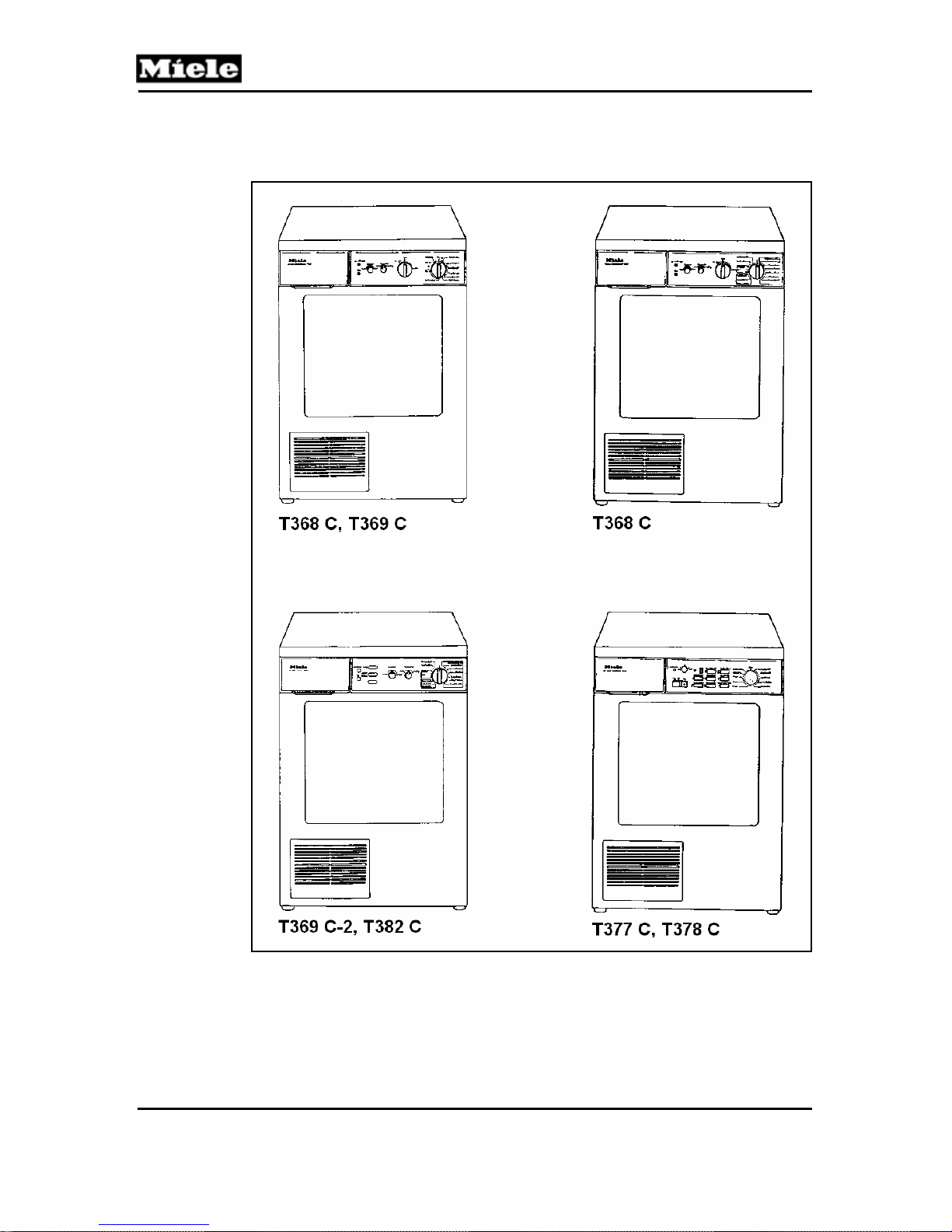
1.0 Construction and Design
Figure 1-1: Overview of Model Numbers (Continued on Figure 1-2)
8
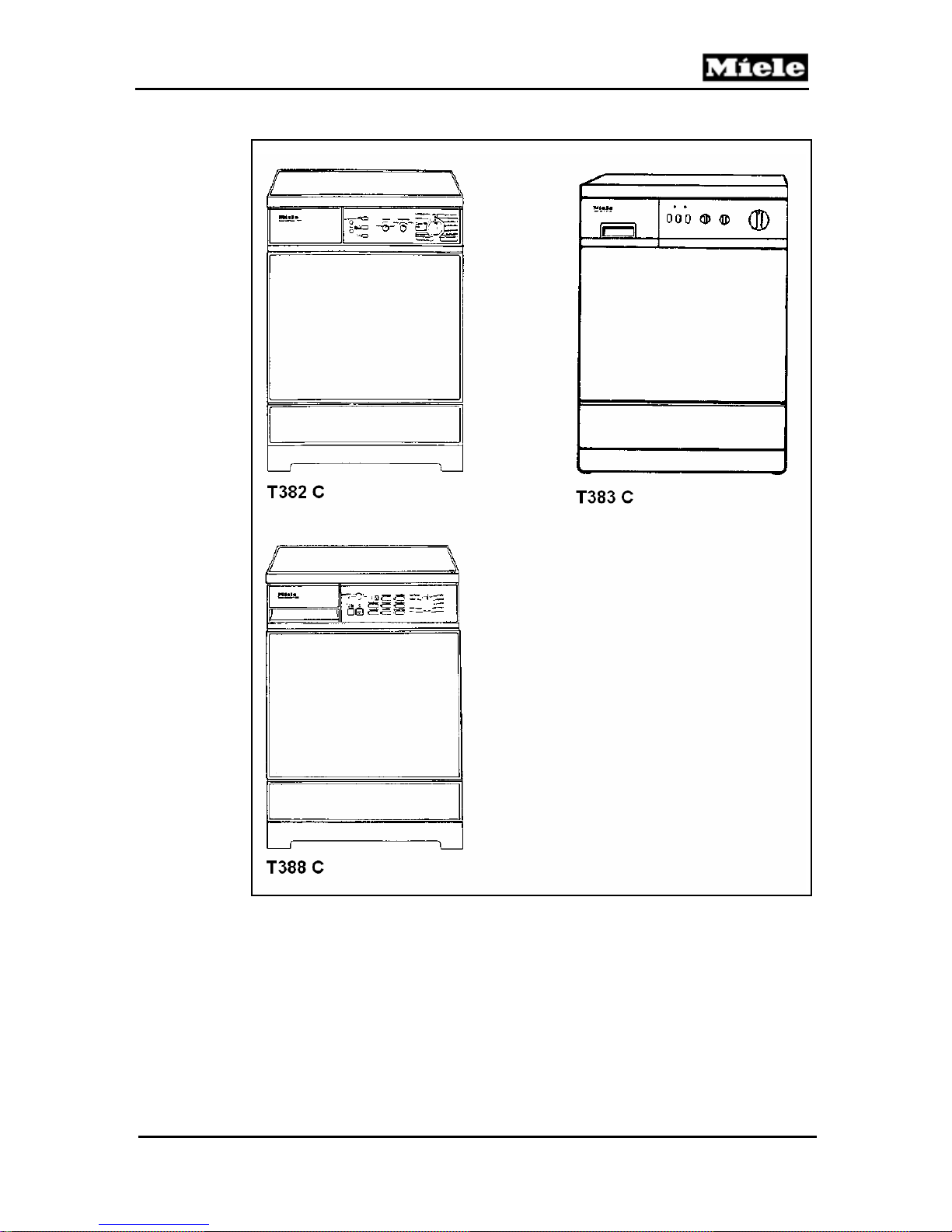
T300 Series Clothes Dryer (Condenser)
Figure 1-2: Overview of Model Numbers (Continued from Figure 1-1)
Technical Information
9
Technical Information
1.1 Features
Air-cooled condenser dryer with reversing motion
Cool air drawn in at the rear
Warm air discharged at the front
Free-standing appliance with laminated worktop
Can be built under with additional kit
Fully opening front panel
1.2 Dimensions
(Values in brackets exclude worktop)
Height:
85cm (82cm) +/- 1
T300 Series Clothes Dryer (Condenser)
Width:
Depth:
Table 1-1: Product Dimensions
59.5 cm
60 cm (57cm)
1.3 Weight
Approx. 60kg
1.4 Capacity
5.0kg dry laundry
1.5 Drum/Volume
Stainless Steel / 103 l
1.6 Casing
MIELE single coat direct enameled
10
T300 Series Clothes Dryer (Condenser)
1.7 Electrical Connection
(German standard models only!)
Voltage:
220V, 50Hz
Technical Information
Connection
Load:
Heater Rating:
Fuse Rating:
Supply Lead:
Table 1-2: Electrical Connection
3.3 kW
2.94 kW
16 A
3-core with Plug
1.8 Drive Motor
180 W, with fan 240 W
1.9 Air Circulation Fan
160 W, 130 m
3
/ h
1.10 Cooling Air Fan
110 W, 320 m
3
/ h
1.11 Condensate Pump
Condensate may be drained to the rear. Refer to Section 1.12 – Rear
Drainage.
1.11.1 T 368 C
20 W, Rear drainage not possible until Machine no. 700201 From
Machine no. 7100202 as Section 1.11.2
1.11.2 T 352 C, T 358 C, T 359 C, T 367 C, T 368 C, T 369 C, T 369 C-2,
T 377 C, T 378 C, T 382 C, T 383 C, T 388 C
20 W, Rear drainage possible.
Max. head height 1.5 m
Max. hose length 6.0 m
11

T300 Series Clothes Dryer (Condenser)
Technical Information
1.12 Rear Drainage
External outlet connection Φ 10.0mm
Outlet connection with non-return valve
T 368 C from Machine no. 8285211
T 369 C from Machine no. 8285737
T 377 C from Machine no. 8285935
T 378 C from Machine no. 8303664
1.12.1 T 352 C, T 358 C, T 359 C, T 367 C, T 369 C, T 369 C-2, T 377 C,
T 378 C, T 382 C, T 383 C, T 388 C
Spares: Drainage Hose 1.5m
Hose holder
Hose spout
1.12.2 T 368 C
Condensate drainage kit available from the Spares Department.
1.13 Condensate Container Drawer
Volume: Approx. 3.7 or 4.0 l
1.14 Condenser Box
Volume: Approx. 0.6 l
1.15 Controls
1.15.1 T 368 C, T 369 C
Timer: MTA 2123
Electronic Module: EF 102
1.15.2 T 368 C, T 369 C-2, T 382 C
Timer: EBR 9701
Electronic Module: EF 202
12

T300 Series Clothes Dryer (Condenser)
Technical Information
1.15.2.1 T 352 C, T 358 C, T 359 C, T 367 C, T 383 C
Timer: EBR 9820/9821
Electronic Module: EF 202
1.15.3 T 377 C, T 378 C, T 388 C
Timer: MTA 605
Sensor-Electronic Module: EPW 304
1.15.4 T 352 C, T 358 C, T 359 C, T 367 C, T 368 C, T 369 C, T 369 C-2,
T 382 C, T 388 C
Temperature Selector: “Normal” or “Low”
1.15.5 T 377 C, T 378 C
Selector pad: “Low Temperature”
1.16 Buzzer
Variable: “Min” – “Max”
1.16.1 T 352 C, T 357 C, T 358 C, T 359 C, T 383 C
Selectable: “On/Off”
1.17 Drum Lightning
1.17.1 T 358 C, T 359 C, T 367 C, T 369 C-2, T 378 C, T 382 C, T 383,
T 388 C
Bulb: E 14, 15 W, 220 V, 300°C
13

T300 Series Clothes Dryer (Condenser)
Technical Information
1.18 Drying Programs
1.18.1 T 368 C, T 369 C, T 377 C, T 378 C, T 388 C
Extra Dry
Normal +
Normal
Hand Iron (1 drop)
Hand Iron (2 drops)
Machine Iron
Cooling Down
1.18.2 T 368 C, T 369 C
1.18.3 T 377 C
1.18.4 T 378 C, T 388 C
1.18.5 T 352 C, T 358 C, T 359 C, T 367 C, T 368 C, T 369 C-2, T 382 C,
Anti-Crease
“Timed drying 30, 20, and 15 minutes”
“Timed drying 30 and 40 minutes” or “Timed drying 20 and 30
minutes”
“Timed drying 20 and 30 minutes”
T 383 C
Cottons
Extra Dry
Normal +
Normal
Hand Iron (1 drop)
Hand Iron (2 drops)
Machine Iron
Minimum Iron
Normal +
Normal
Timed Drying
30, 20, and 15 min
All programs have “Cooling Down” and “Anti-Crease” phases.
14
T300 Series Clothes Dryer (Condenser)
1.19 Consumption Data
Values determined in accordance with DIN 0044986. (Laundry spun at
1200 rpm reduces consumption by approx. 25 %).
Load
4.5 kg
Technical Information
Load
5.0kg
Drying Time (minutes)
Energy Consumption
(kWh)
Table 1-3: Consumption Data
76 83
3.6 4.0
15

T300 Series Clothes Dryer (Condenser)
Technical Information
2.0 Installation
T 352 C, T 358 C, T 359 C, T 367 C, T 368 C, T 369 C, T 369 C-2, T 377
C, T 378 C, T 382, T 383 C, T 388 C
2.1 Installation as a Free-Standing Unit
To ensure fault-free operation, the appliance should be installed perfectly
level.
Any unevenness in the floor can be compensated for by adjusting the
2.2 Installation under a Continuous Worktop
2.2.1 Models with Half Closed Base Plate (Initial Production Models)
2.2.2 Models with Fully Closed Base Plate
screw-in feet at all four corners.
To correctly install the appliance under a continuous worktop, a “building
under” kit is required. Fitting instructions, Part no. 1508041, are included
with the kit.
Building a machine under can slightly increase drying times but does not,
though, affect energy consumption.
These models can be built-in under certain conditions. It is essential to
ensure that sufficient air can be taken in at the
rear of the machine.
They may be installed next to a washing machine. However, if the
washing machine has a décor panel front then the service panel sealing
strip should not be fitted so that air intake can also take place in this area.
If the dryer is built-in alone, gaps for air intake must total at least 100 cm2.
The approx. 10mm gap along the machine’s lower front edge should
never be reduced or blocked by deep pile carpets, skirting strips or tiles,
etc.
These models can be built-in. It is essential to ensure that sufficient air
can be taken in at the front of the machine.
The approx. 10 mm gap along the machine’s lower front edge should
never be reduced or blocked by deep pile carpets, skirting strips or tiles,
etc.
16
T300 Series Clothes Dryer (Condenser)
2.3 Installation as a Washer-Dryer Stack
If the appliance is to be installed as a stack, together with a washing
machine, one of the following stacking kits will be required:
Washing Machine Tumble Dryer Stacking Kit Instructions Part No.
Technical Information
e.g. W 760
e.g. W 436
Table 2-1: Stacking Kits
* without shelf between units
** with pull-out shelf between units
T 368 C
or similar
T 368 C
or similar
WTV 310 *
WTV 311 **
WTV 302 1313950
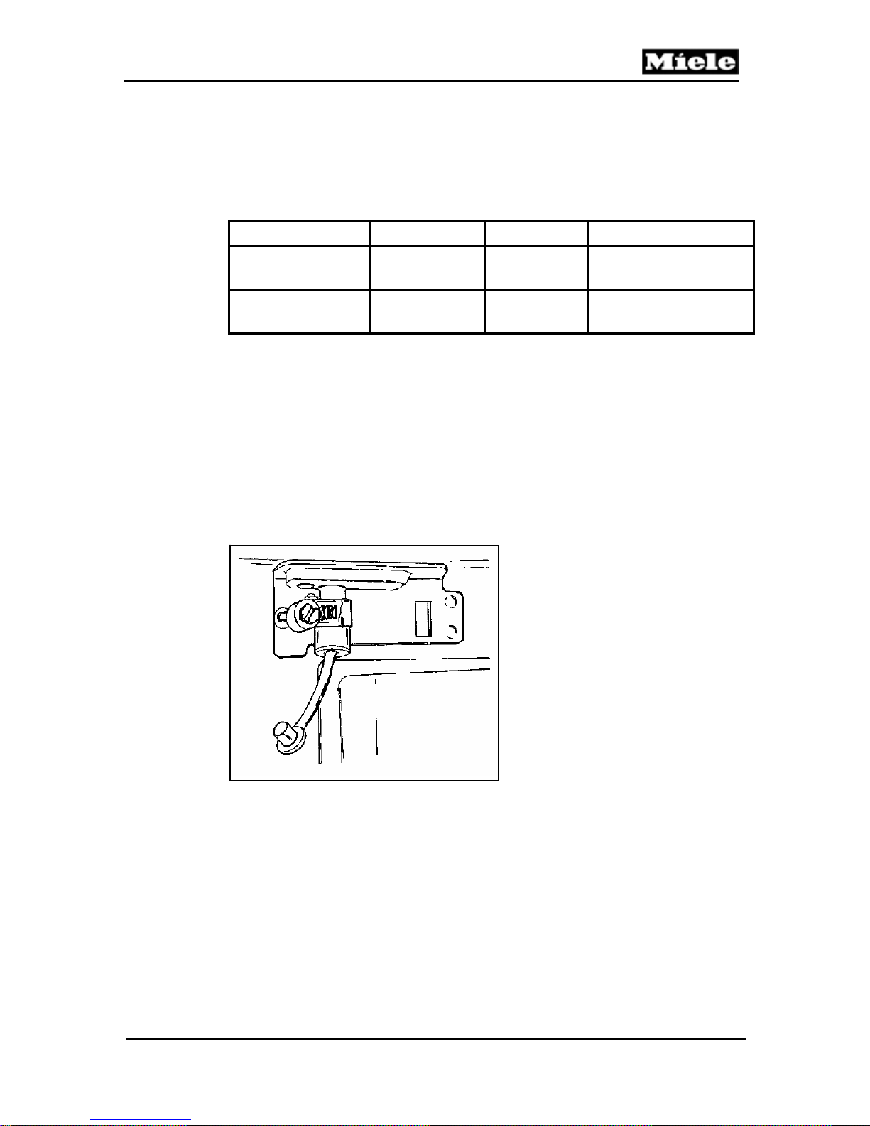
2.4 Draining Condensate to the Rear
T 352 C, T 358 C, T 359 C, T 367 C, T 369 C, T 369 C-2, T 377 C, T 378
C, T 382 C, T 383 C, T 388 C (T 368 C from Machine no. 7100202)
Figure 2-1: Draining Condensate to the Rear
1. Unscrew the clip from the outlet connection and remove the rubber
seal (refer to Figure 2-1 – Draining the Condensate to the Rear).
2. Fit the drain hose supplied (not with T 368 C) or other suitable hose
and affix it with the clip (refer to Section 1.12.1 Rear Drainage).
1487500
17
Technical Information
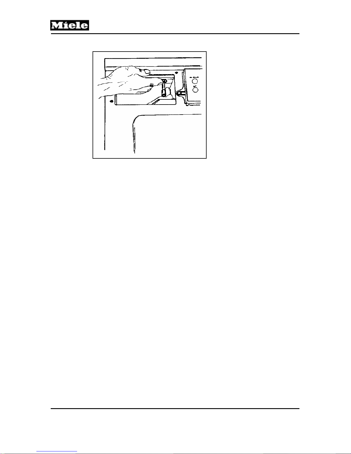
Figure 2-2: Opening the Condenser Drawer
3. Use the stopper to close the water inlet opening to the condenser
drawer (refer to Figure 2-2 – Opening the Condenser Drawer).
T300 Series Clothes Dryer (Condenser)
18

T300 Series Clothes Dryer (Condenser)
Technical Information
4.0 Description of Function
T 352 C, T 358 C, T 359 C, T 367 C, T 368 C, T 369 C, T 369 C-2, T 377
C, T 378 C, T 382 C, T 383 C, T 388 C
4.1 Electronic Residual Moisture Detection Unit EF 102
As with most other Miele household dryers, the drying stages of this
appliance are electronically monitored and controlled. As can be seen in
the block diagram, the desired level of dryness (i.e. the desired residual
moisture level) set at the timer is passed via the printed circuit and the
pulse generator stage to the residual moisture comparator.
The 4 minute time stage prevents the timer from advancing to the next
stage too early after switching on if the level switch has not reset.
The stainless-steel drum body and its internal ribs serve as sensor
contacts to monitor the residual moisture content of the load. Once the
required dryness level has been detected, a control stage lasting 1 minute
begins. The timer will not advance to the next stage of the program
unless the correct moisture level is maintained throughout this control
stage.
The level switch closes when the condensate collector becomes too full.
This switches a relay which then sends step impulses to the timer, until it
has advanced to the “Stop” position, and also switches an LED indicator
on.
Figure 4-1: Electronic Residual Moisture Detection Unit EF 102
19
T300 Series Clothes Dryer (Condenser)
Technical Information
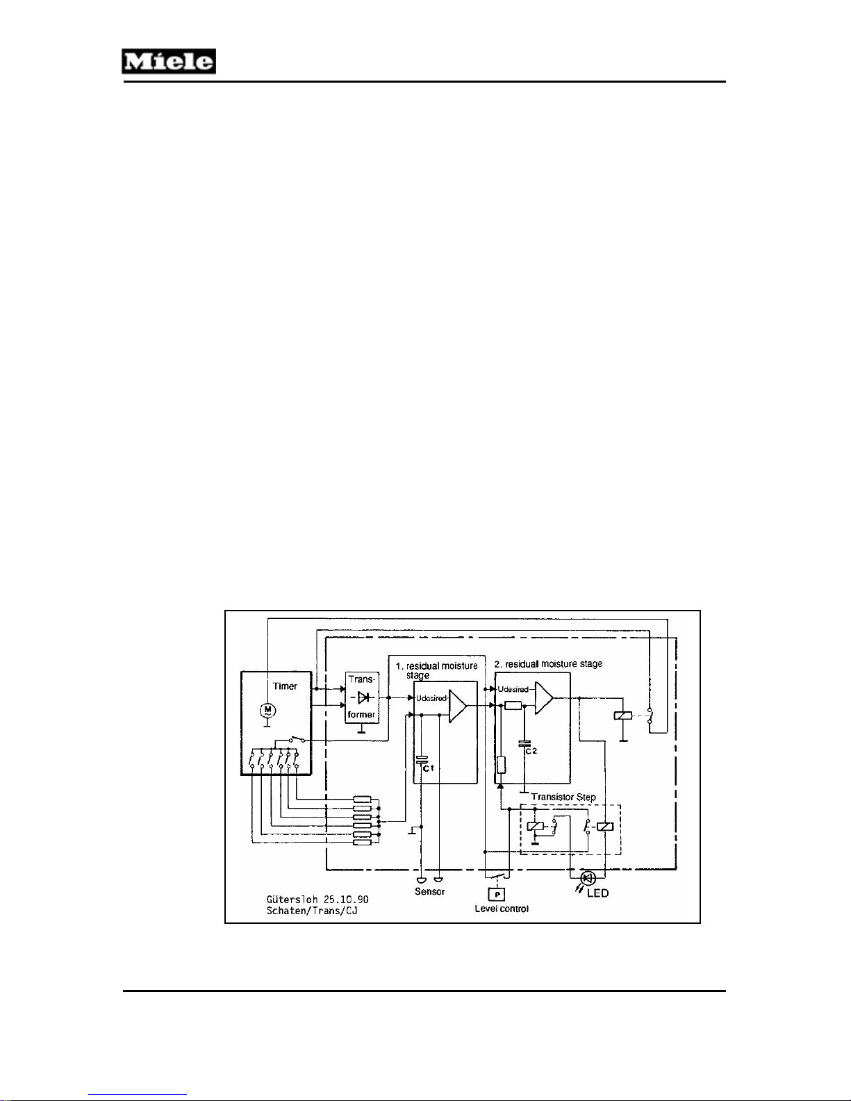
4.2 Electronic Residual Moisture Detection Unit EF 202
A low voltage signal (approx. 33 V) is passed from the electronic unit
transformer to the timer. From there, it is returned, via the timer contacts,
to the electronic unit.
This signal then charges the capacitor C1, which is in turn discharged, via
the sensors, by the damp (conductive) load in the drum.
During the drying process, the load becomes less conductive and the
capacitor C1 is charged until the desired value (Udesired) of the first
residual moisture stage is reached. At this point, charging of capacitor C2
begins. After a further minute has elapsed, this capacitor is also fully
charged, providing that no discharge has occurred due to damp items of
laundry coming into contact with the sensors.
4.2.1 Level Control
If, either due to a fault or operator error, the condensed water container is
too full, then the level switch is activated.
The level switch sends a DC signal to the second residual moisture stage.
After approx. 3.5 seconds, this switches both the stepping relay on, which
advances the timer to the “Cool Air” cycle, and also the LED warning light.
The transistor switching stage retains this state until the machine is
switched off.
Figure 4-2: Electronic Residual Moisture Detection Unit EF 202
20
 Loading...