

Page 1

Operating instructions
for hob control units
SE 213, SE 233
It is essential to read these
operating instructions before
installing or using the machine,
to avoid the risk of accident,
or damage to the machine. M.-Nr. 04 392 021
Q\@ä}
Page 2
Contents
Contents
Description of the appliance . . . . . . . . . . . . . . . . . . . . . . . . . . . . . . . . . . . . . . . . . 3
Caring for the environment . . . . . . . . . . . . . . . . . . . . . . . . . . . . . . . . . . . . . . . . . . 4
Warning and Safety instructions . . . . . . . . . . . . . . . . . . . . . . . . . . . . . . . . . . . . . 5
Safety feature . . . . . . . . . . . . . . . . . . . . . . . . . . . . . . . . . . . . . . . . . . . . . . . . . . . . . 7
Maintenance
Cleaning and care
– Appliance front, controls . . . . . . . . . . . . . . . . . . . . . . . . . . . . . . . . . . . . . . . . . . . 8
After sales service . . . . . . . . . . . . . . . . . . . . . . . . . . . . . . . . . . . . . . . . . . . . . . . . . . 9
Preparation for use
Electrical connection . . . . . . . . . . . . . . . . . . . . . . . . . . . . . . . . . . . . . . . . . . . . . . . 10
Installation
– Installation in a base unit . . . . . . . . . . . . . . . . . . . . . . . . . . . . . . . . . . . . . . . . . . 12
– Installation in a wall unit . . . . . . . . . . . . . . . . . . . . . . . . . . . . . . . . . . . . . . . . . . . 16
Please consult the operating instructions supplied with the hob, for details on its use.
Page 3
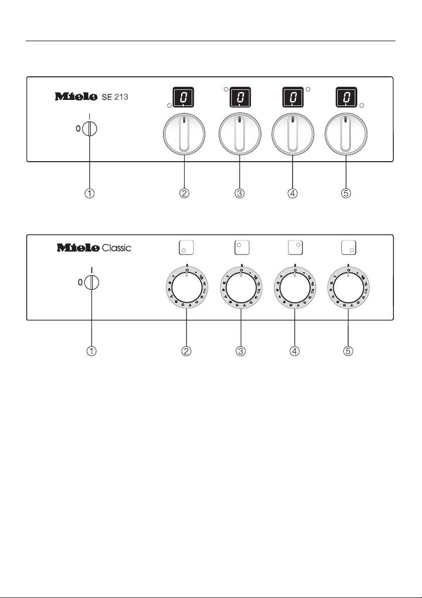
Description of the appliance
SE 213
SE 233
Description of the appliance
Hob lock
b
c Cooking zone control: front left
d Cooking zone control: back left
e Cooking zone control: back right
f Cooking zone control: front right
Data plate
When the control unit has been built in the data plate can not be seen.
A further data plate is supplied with this appliance. Please stick this into the
booklet in the frame in the section "After Sales service".
3
Page 4

Caring for the environment
Caring for the environment
Disposal of the packing
material
The transport and protective packing
has been selected from materials
which are environmentally friendly for
disposal and can normally be recycled.
Rather than just throwing these materials away, please ensure they are offered for recycling.
Disposal of your old machine
Old machines contain materials which
can be reclaimed or recycled. Please
contact your dealer, your local waste
collection centre or scrap merchant
about potential recycling schemes.
Ensure that the machine presents no
danger to children.
4
Page 5
Warning and Safety instructions
This appliance complies with all relevant legal safety requirements. Improper use of the appliance can,
however, present a risk of both personal injury and material damage.
Before installation and before using
the appliance for the first time, read
the operating instructions carefully.
They contain important notes on
safety, on the operation and care of
the appliance. This way you will.
avoid the risk of accidents and damage to the appliance.
Do not let children access the appliance or its controls. Supervise its
use by the elderly or infirm.
Keep these instructions in a safe
place and pass them on to any future user.
Warning and Safety instructions
Technical safety
Before connecting the appliance to
the mains supply make sure that
the voltage and frequency correspond
to the rating on the data plate. Consult
a competent person if in doubt.
The electrical safety of this ap-
pliance can only be guaranteed
when continuity is complete between
the appliance and an effective earthing
system, which complies with local and
national regulations. It is most important that this basic safety requirement is
tested by a qualified electrician. The
manufacturer cannot be held responsible for the consequences of an inadequate earthing system.
This appliance must only be oper-
ated as a built-in appliance. This is
necessary to ensure that all electrical
components are shielded.
Correct usage
The appliance in combination with
a Miele hob / cooktop is intended
for domestic use to cook food, and in
particular to boil, simmer, stew, fry and
re-heat foods. Any other usage is at the
owner’s risk and could be dangerous.
The manufacturer cannot be held responsible for damage caused by improper use of the appliance.
Installation work and repairs may
only be carried out by suitably
qualified and competent persons to ensure safety. Repairs and other work by
unqualified persons could be dangerous.
5
Page 6
Warning and Safety instructions
The appliance is only completely
isolated from the electricity supply
when:
– it is switched off at the wall socket
– or the mains fuse is withdrawn.
– or the screw-out fuse is removed (in
countries where this is applicable).
Do not connect the appliance to
the mains electricity supply by an
extension lead.
Extension leads do not guarantee the
required safety of the appliance.
Caution:
The underside surface of the cooking hob can reach a temperature exceeding 105°C during normal use. If
after installation the underside surface
is accessible through under-bench cupboard doors and the like, it is essential
that a rigid barrier is installed so that
such access is restricted. In order to
avoid a hazard the barrier must be of
low thermal conductivity material installed according to the instructions for
installation.
In areas which may be subject to
infestation by cockroaches or other
vermin, pay particular attention
to keeping the appliance and its surroundings in a clean condition at all
times. Any damage which might be
caused by cockroaches or other vermin will not be covered by the appliance guarantee.
Disposal of your old machine
Before discarding an old machine
switch off and disconnect it from
the power supply. Cut off and render
any plug useless.
Cut off the cable directly behind the machine to prevent misuse.
The manufacturer cannot be held
liable for damage caused by noncompliance with safety instructions.
If no wooden protective board is
fitted between the hob and a
drawer underneath, spray canisters or
inflammable substances must not be
stored in the drawer. Any cutlery trays
must be made of a heat resistant material.
6
Page 7
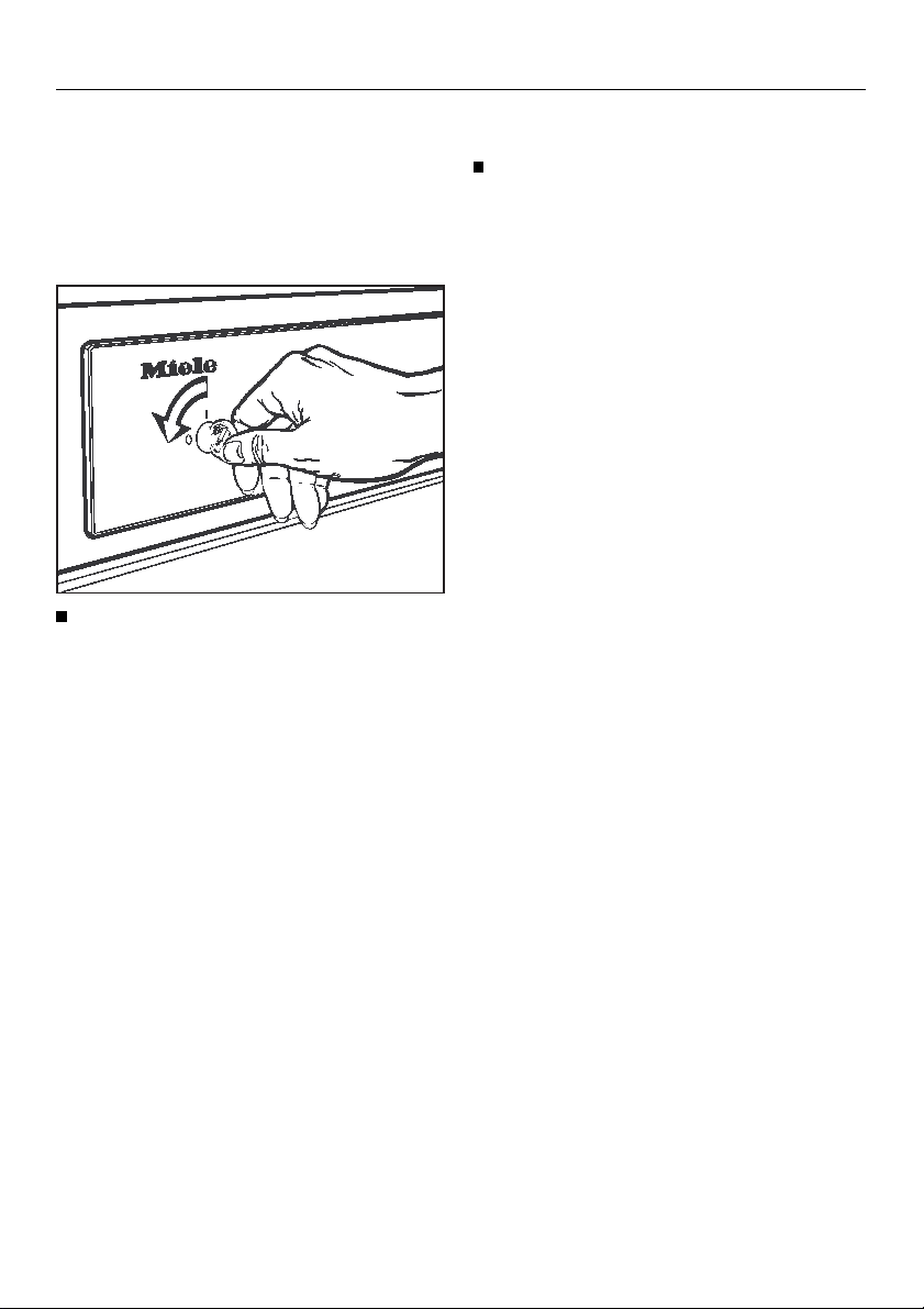
Safety feature
Hob lock
The hob lock can be set so that the
cooking zones cannot be turned on.
To set the lock:
Use a coin to turn the slit to the "0"
setting.
The cooking zones cannot now be
turned on.
Safety feature
To undo the lock:
Use a coin to turn the slit to the "I"
setting.
The cooking zones can be used again.
7
Page 8
Cleaning and care
Cleaning and care
Appliance front and control
panel
Use a mild cleaning agent or a dash of
detergent in hot water. Wipe dry with a
soft cloth.
Glass front
Do not use a scouring agent, as this
would scratch the glass front.
Stainless steel front
Never use cleaners containing
sand, soda or scouring agents,
These will leave scratches.
Use a non-scouring stainless steel
cleaner. Apply with an even pressure.
Wipe over with a damp cloth and rub
dry with a soft cloth.
8
Page 9

After sales service
In the event of faults which you cannot
remedy yourself, please contact:
– your Miele Dealer
or
– the nearest Miele Service Depart-
ment, (see address on the back
page).
After sales service
When contacting the Service dept,
please quote the Model and Serial number of your appliance, both of which
are shown on the data plate.
Please also quote the model and serial
number of your hob.
Space for data plates for the control
unit and the hob.
9
Page 10
Electrical connection
Electrical connection
All electrical work should be undertaken by a competent person in
strict accordance with national and
local safety regulations.
Connection of this appliance should be
made via a suitable isolator which complies with national and local regulations, and which is accessible after the
appliance has been built in.
Q\}
Q\}
WARNING
THIS APPLIANCE MUST BE
EARTHED.
If the connection requires a different
cable, the Miele Service dept must
be consulted.
See the data plate for the maximum
rated load.
The voltage, rated load and fusing
are given on the data plate, located at
the rear of the appliance. Please ensure that these match the household
mains supply.
Please quote these data, and the
model and serial number when contacting the Miele Service dept.
A second data plate is also supplied.
For extra safety it is advisable to install
a residual current device with a trip current of 30 mA.
Control unit
Important U.K.
The appliance is supplied with a 3-core
cable for connection to a 230-240 volt
50 Hz supply.
The wires are coloured in accordance
with the following code:
Possible combinations
The hob control units may only be combined with one of the hobs listed below,
(not all units are available in every
country):
Hob
Hob electronic
control
KM 220
KM 221
KM 222
KM 230
KM 232
KM 240
KM 242
KM 243
KM 245
KM 246
KM 247
KM 248
KM 251 KSE 204-1
KSE 200
KSE 202-1
Green/yellow = earth
Blue = neutral
Brown = live
10
Page 11

Electrical connection
Q\}
\
The fuse rating must be be in accordance to national and local standards.
The appliance is supplied with a 3-core
cable for connection to a 230-240 volt
50 Hz supply.
The wires are coloured in accordance
with the following code:
Green/yellow = earth
Blue = neutral
Brown = live
The fuse rating is 32 amps.
The control unit is fitted with an approx.
1.8 metres long cable.
WARNING
THIS APPLIANCE MUST BE
EARTHED.
If the connection requires a different
cable, the Miele Service dept must
be consulted.
See the data plate for the maximum
rated load.
}
Data relating to electrical connection
will be found on the data plate, located
at the rear of the appliance.
Make sure that these figures comply
with the main voltage.
Connection of this appliance should be
made via a suitable isolator which complies with national and local regulations
The appliance is supplied with a 3-core
cable for connection to a 230-240 volt
50 Hz supply.
The wires are coloured in accordance
with the following code:
Green/yellow = earth
Blue = neutral
Brown = live
The fuse rating is 32 amps.
The control unit is fitted with an approx.
1.8 metres long cable.
WARNING
THIS APPLIANCE MUST BE
EARTHED.
If the connection requires a different
cable, the Miele Service dept must
be consulted.
11
Page 12

Electrical connection
Electrical connection
Electrical connection of the
appliance should be undertaken by
a qualified electrician in strict accordance with national and local
safety regulations.
Caution:
In order to avoid a hazard this appliance must be installed according
to these instructions for installation.
Fusing arrangements must be according to national and local standards.
Connection should be made via a suitable isolator switch which complies
with national and local regulations. It
should be easily accessible for servicing work.
The data plate, located at the rear of
the appliance, gives the necessary
connection rating, which must be according to national and local standards.
@ä
@ä
The wire which is coloured green and
yellow must be connected to the terminal in the plug which is marked with the
letter E or by the earth symbol z or
coloured green or green and yellow.
The wire which is coloured blue must
be connected to the terminal which is
marked with the letter N or coloured
black.
The wire which is marked brown must
be connected to the terminal which is
marked with the letter A or coloured red.
WARNING
THIS APPLIANCE MUST BE
EARTHED.
When contacting the Service Department, please quote the voltage, model
and serial numbers given on the data
plate.
12
Page 13

Electrical connection
@ä
The built-in control unit is suitable for
connection to an a.c. single phase
230 V-240 V, 50 Hz electricity supply.
@
Built-in control unit
The fuse rating is 25 amps for SE 213
and SE 233 (max. rated load 8400 W)
with hob.
ä
Built-in control unit
The fuse rating is 25 amps for SE 213
and SE 233 (max. rated load 7800 W)
with hob.
Possible combinations
The built-in control unit can only be
combined with one of the hobs listed
below and the appropriate hob-integrated control unit:
Hob Hob electronic control
KM 243
KM 247
KM 251 KSE 204-1
KSE 202-1
13
Page 14

Installation
Installation
Control unit and hob electronic control
Building into a base unit
The control unit must be separated
by a removable shelf from the rest
of the space in the base unit, to
make it inaccessible.
Disconnect the mains electricity
supply to the appliance.
Install the hob.
Before building in the control unit
pull the control knobs out of the
openings in the facia.
Draw out the control unit from the retaining plate.
Set the control unit retaining plate
into the cut-out base unit facia.
Fix the retaining plate to the side
edges of the base unit cut-out with
2 screws on each side.
14
Page 15

Installation
The plugs on the control unit / hob
and the sockets on the hob electronic control are coded with the
same colour for matching.
Fit the plugs into the sockets.
Insert the knobs for the control unit
into the control facia.
Put the hob electronic control into
the control unit.
15
Page 16

Installation
Fit the hob plugs into the sockets.
Feed the connection cable without a
plug through a suitable hole in the
base unit. Connect to the electricity
supply with an isolator which complies with national and local regulations.
When pushing the control unit into
place, ensure that no connecting
cables are crushed or caught.
The mains cable must not come into
contact with the underside of the
hob. Pull any superfluous cable
away from the space behind the
control unit when it is pushed in.
Push the control unit into the retaining plate.
The pins of the control unit must securely fit into the retainers on the retaining plate.
Fit the protective shelf under the control unit and secure it.
The appliance must only be operated when it has been built-in.
16
Page 17

Installation
For Australia / New Zealand only:
660
b hob
work top
c
d control unit
e protective shelf below
f back wall of unit
For safety reasons, a protective shelf
must be installed as shown to ensure
that inadvertant contact with the hot
underside is prevented.
The distance between the lower
edge of the worktop and the upper
edge of the removable barrier must
be a minimum of 125 mm.
In order to ensure sufficient air circulation, a gap of 20 mm must be left
between the protective shelf and
the rear panel of the base unit, and
a gap of 5 mm must be left between
the cabinet front panel and the
benchtop.
17
Page 18

Installation
Installation
Building into a wall unit
To install a control unit at "eye level" a
special accessory kit is required for
connection to the hob.
This unit is obtainable from your Miele
dealer, or the Miele Spare Parts dept,
and consists of a 3.5 metre long connecting cable and an additional connector box.
For some control units two cable and
connector box accessory kits are required:
Hob electronic control
KSE 200 1
KSE 202 2
KSE 204 2
No. of connecting
cable kits
The cable should be in conduit approved by the electricity regulatory
bodies. Only a suitably competent
person should install the connecting
cable from the control unit to the
hob.
18
Page 19

Installation
e connection cabling
(in ducting behind plaster)
f connection cabling
(in ducting behind the wall units)
The control unit must be built in
within view of the hob.
19
Page 20

Installation
The cable conduit must meet statutory electrical requirements and
have an inner diameter of at least
23 mm for data cable und 29 mm
for power cable.
The conduit length should be sufficient to ensure the cable cannot be
touched for the whole distance between the additional connector box
and thecontrol unit.
Do not install the control unit directly
above a hob or an oven. Exposure
to direct heat could be damaging.
The control unit must be separated
by a secured shelf from the rest of
the space in the wall unit, to make it
inaccessible.
Disconnect the mains electricity
supply to the appliance.
Install the hob.
Starting from the wall unit push the
cables into the ducting.
The plugs on the connecting cables
and the sockets on the hob are
coded with the same colour for
matching.
Connect the plugs of the connecting
cables into the corresponding
sockets on the additional connection
box, and connect the individual
wires according to the wiring plan
supplied.
Secure the connecting cables in the
connection box with the strain relief
clip.
Fit the hob plug into the socket.
20
Page 21

Installation
Screw the additional connector box
to the protective shelf underneath
the hob.
b protective shelf above
c control unit
d wall unit facia cut-out
e cable in ducting
g hob
h
cable to hob
i additional connector box
j protective shelf below
k back wall of unit
In doing so make sure the connection
box is as close to the back wall of
the unit as possible.
The ducting for the electric cabling
must continue right up to the additional connection box.
The connection cables must not
come into contact with the underside of the hob. This is a fire hazard.
Pull any superfluous cable away
from the space under the hob.
Fire hazard!
21
Page 22

Installation
Before building in the control unit
pull the control knobs out of the
openings in the facia.
Draw out the control unit from the retaining plate.
Set the control unit retaining plate
into the furniture unit cut-out.
Fix the retaining plate to the side
edges of the unit cut-out with 2
screws on each side.
22
Put the hob electronic control into
the control unit.
Page 23

Installation
The plugs on the control unit / the
connection cable and the sockets
on the hob electronic control are
coded with the same colour for
matching.
Fit the plugs of the control unit into
the sockets.
Insert the knobs for the control unit
into the control facia.
Pull the connection cables as far as
possible in the direction of the control unit, and roll up if possible.
Fit the connection cable plugs into
the sockets.
23
Page 24

Installation
Use the cable clamp to secure the
cables together.
Feed the connection cable through a
suitable hole in the base unit. Connect to the electricity supply with an
isolator which complies with national
and local regulations.
When pushing the control unit into
place, ensure that no connecting
cables are crushed or caught.
24
Push the control unit into the retaining plate.
The pins of the control unit must securely fit into the retainers on the retaining plate.
Fit the protective shelf and secure it.
The appliance must only be operated when it has been built-in.
Page 25

Installation
For Australia / New Zealand only:
b protective shelf above
c control unit
d wall unit facia cut-out
e cable in ducting
g hob
h cable to hob
i additional connector box
j protective shelf below
k back wall of unit
For safety reasons, a protective shelf
must be installed as shown to ensure
that inadvertant contact with the hot
underside is prevented.
The distance between the lower
edge of the worktop and the upper
edge of the protective shelf must be
a minimum of 125 mm.
In order to ensure sufficient air circulation, a gap of 20 mm must be left
between the protective shelf and
the rear panel of the base unit, and
a gap of 5 mm must be left between
the cabinet front panel and the
benchtop.
252627
Page 26

Page 27

Page 28

Alterations rights reserved / 22 GB / IRL / AUS / NZ / ZA – 1597
M.-Nr. 04 392 021
This paper consists of cellulose which has been bleached without the use of chlorine.
 Loading...